
Low voltage circuit breakers
Super Solution
ComprehensiveCatalogue
2006

A-2. Main characteristics TD & TS MCCB Index
MCCBs for power distributionElectrical characteristics
Thermal magnetic trip units
Overview
FTU, FMU for TD100, TD160
FTU, FMU for TS100, TS160, TS250
ATU for TS160, TS250
FTU, FMU, ATU for TS400, TS630
FTU, FMU, ATU for TS800
Overview of electronic trip units (Standard type)
Electronic trip units (Standard)
ETS23 for TS100, TS160, TS250
ETS33 for TS400, TS630
ETS43 for TS800
Electronic trip units (Multifunction)
Overview
ETM33 for TS400, TS630
ETM43 for TS800
MCCBs for motor protectionElectrical characteristics
Magnetic only trip unit
MTU for TS100, TS250, TS400, TS630, TS800
Switch-Disconnectors
A-2-1
A-2-3
A-2-5
A-2-7
A-2-11
A-2-15
A-2-17
A-2-19
A-2-25
A-2-31
A-2-37
A-2-40
A-2-49
A-2-57
A-2-59
A-2-61
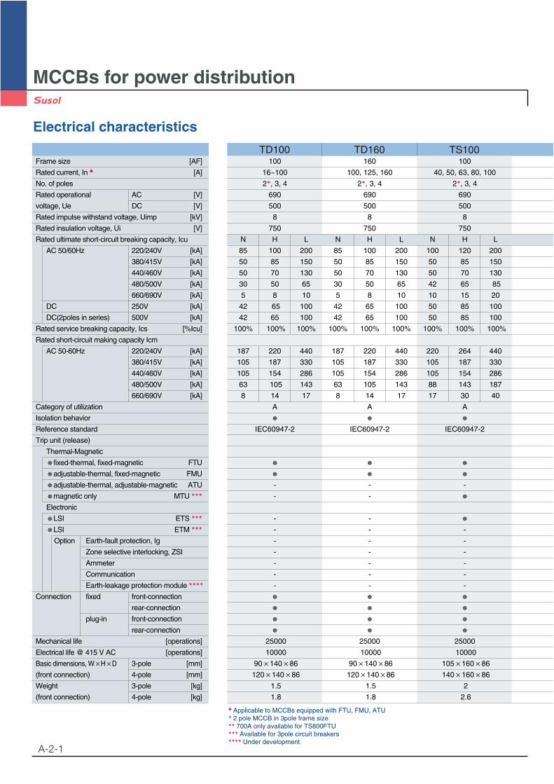
MCCBs for power distribution
A-2-1
Electrical characteristics
TD100 TD160 TS100
Applicable to MCCBs equipped with FTU, FMU, ATU2 pole MCCB in 3pole frame size700A only available for TS800FTUAvailable for 3pole circuit breakersUnder development
Frame size [AF]
Rated current, In [A]
No. of poles
Rated operational AC [V]
voltage, Ue DC [V]
Rated impulse withstand voltage, Uimp [kV]
Rated insulation voltage, Ui [V]
Rated ultimate short-circuit breaking capacity, Icu
AC 50/60Hz 220/240V [kA]
380/415V [kA]
440/460V [kA]
480/500V [kA]
660/690V [kA]
DC 250V [kA]
DC(2poles in series) 500V [kA]
Rated service breaking capacity, Ics [%Icu]
Rated short-circuit making capacity Icm
AC 50-60Hz 220/240V [kA]
380/415V [kA]
440/460V [kA]
480/500V [kA]
660/690V [kA]
Category of utilization
Isolation behavior
Reference standard
Trip unit (release)
Thermal-Magnetic
fixed-thermal, fixed-magnetic FTU
adjustable-thermal, fixed-magnetic FMU
adjustable-thermal, adjustable-magnetic ATU
magnetic only MTU
Electronic
LSI ETS
LSI ETM
Option Earth-fault protection, Ig
Zone selective interlocking, ZSI
Ammeter
Communication
Earth-leakage protection module
Connection fixed front-connection
rear-connection
plug-in front-connection
rear-connection
Mechanical life [operations]
Electrical life @ 415 V AC [operations]
Basic dimensions, W H D 3-pole [mm]
(front connection) 4-pole [mm]
Weight 3-pole [kg]
(front connection) 4-pole [kg]
100 160 100
16~100 100, 125, 160 40, 50, 63, 80, 100
2 , 3, 4 2 , 3, 4 2 , 3, 4
690 690 690
500 500 500
8 8 8
750 750 750
N H L N H L N H L
85 100 200 85 100 200 100 120 200
50 85 150 50 85 150 50 85 150
50 70 130 50 70 130 50 70 130
30 50 65 30 50 65 42 65 85
5 8 10 5 8 10 10 15 20
42 65 100 42 65 100 50 85 100
42 65 100 42 65 100 50 85 100
100% 100% 100% 100% 100% 100% 100% 100% 100%
187 220 440 187 220 440 220 264 440
105 187 330 105 187 330 105 187 330
105 154 286 105 154 286 105 154 286
63 105 143 63 105 143 88 143 187
8 14 17 8 14 17 17 30 40
A A A
IEC60947-2 IEC60947-2 IEC60947-2
- - -
- -
- -
- - -
- - -
- - -
- - -
- - -
- - -
25000 25000 25000
10000 10000 10000
90 140 86 90 140 86 105 160 86
120 140 86 120 140 86 140 160 86
1.5 1.5 2
1.8 1.8 2.6
A-2-2
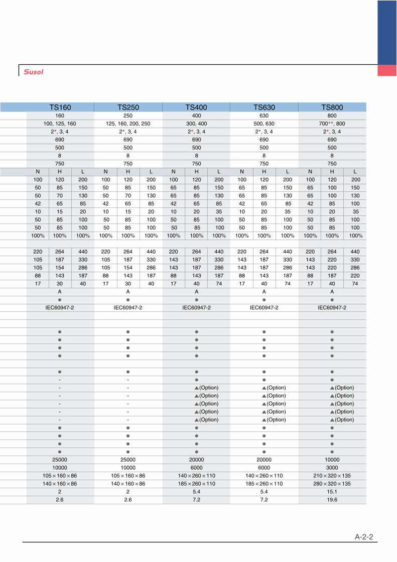
TS160 TS250 TS400 TS630 TS800160 250 400 630 800
100, 125, 160 125, 160, 200, 250 300, 400 500, 630 700 , 800
2 , 3, 4 2 , 3, 4 2 , 3, 4 2 , 3, 4 2 , 3, 4
690 690 690 690 690
500 500 500 500 500
8 8 8 8 8
750 750 750 750 750
N H L N H L N H L N H L N H L
100 120 200 100 120 200 100 120 200 100 120 200 100 120 200
50 85 150 50 85 150 65 85 150 65 85 150 65 100 150
50 70 130 50 70 130 65 85 130 65 85 130 65 100 130
42 65 85 42 65 85 42 65 85 42 65 85 42 85 100
10 15 20 10 15 20 10 20 35 10 20 35 10 20 35
50 85 100 50 85 100 50 85 100 50 85 100 50 85 100
50 85 100 50 85 100 50 85 100 50 85 100 50 85 100
100% 100% 100% 100% 100% 100% 100% 100% 100% 100% 100% 100% 100% 100% 100%
220 264 440 220 264 440 220 264 440 220 264 440 220 264 440
105 187 330 105 187 330 143 187 330 143 187 330 143 220 330
105 154 286 105 154 286 143 187 286 143 187 286 143 220 286
88 143 187 88 143 187 88 143 187 88 143 187 88 187 220
17 30 40 17 30 40 17 40 74 17 40 74 17 40 74
A A A A A
IEC60947-2 IEC60947-2 IEC60947-2 IEC60947-2 IEC60947-2
- -
- - (Option) (Option) (Option)
- - (Option) (Option) (Option)
- - (Option) (Option) (Option)
- - (Option) (Option) (Option)
- - (Option) (Option) (Option)
25000 25000 20000 20000 10000
10000 10000 6000 6000 3000
105 160 86 105 160 86 140 260 110 140 260 110 210 320 135
140 160 86 140 160 86 185 260 110 185 260 110 280 320 135
2 2 5.4 5.4 15.1
2.6 2.6 7.2 7.2 19.6
MCCBs for power distribution
A-2-3
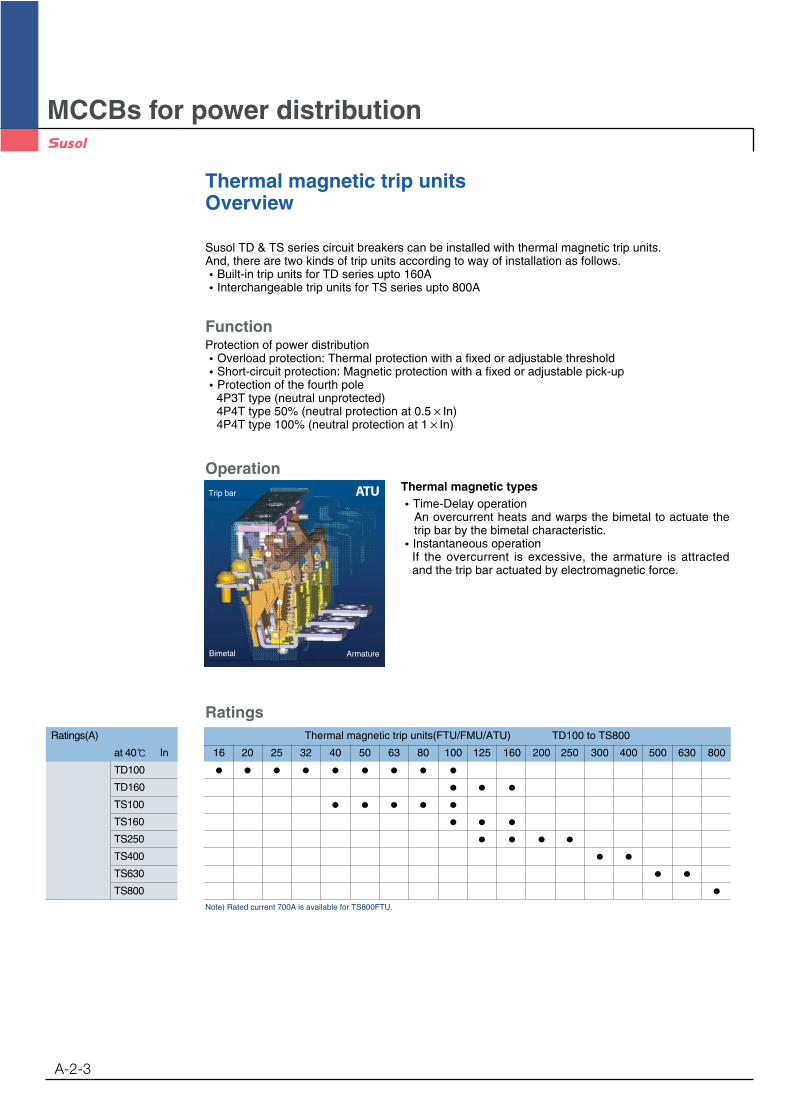
Thermal magnetic trip unitsOverview
Susol TD & TS series circuit breakers can be installed with thermal magnetic trip units. And, there are two kinds of trip units according to way of installation as follows.
Built-in trip units for TD series upto 160AInterchangeable trip units for TS series upto 800A
FunctionProtection of power distribution
Overload protection: Thermal protection with a fixed or adjustable thresholdShort-circuit protection: Magnetic protection with a fixed or adjustable pick-upProtection of the fourth pole4P3T type (neutral unprotected)4P4T type 50% (neutral protection at 0.5 In)4P4T type 100% (neutral protection at 1 In)
Thermal magnetic typesTime-Delay operationAn overcurrent heats and warps the bimetal to actuate thetrip bar by the bimetal characteristic.Instantaneous operationIf the overcurrent is excessive, the armature is attractedand the trip bar actuated by electromagnetic force.
OperationATU
Ratings
Note) Rated current 700A is available for TS800FTU.
Ratings(A)
at 40 In
TD100
TD160
TS100
TS160
TS250
TS400
TS630
TS800
Thermal magnetic trip units(FTU/FMU/ATU) TD100 to TS800
16 20 25 32 40 50 63 80 100 125 160 200 250 300 400 500 630 800
ArmatureBimetal
Trip bar
MCCBs for power distribution
A-2-4
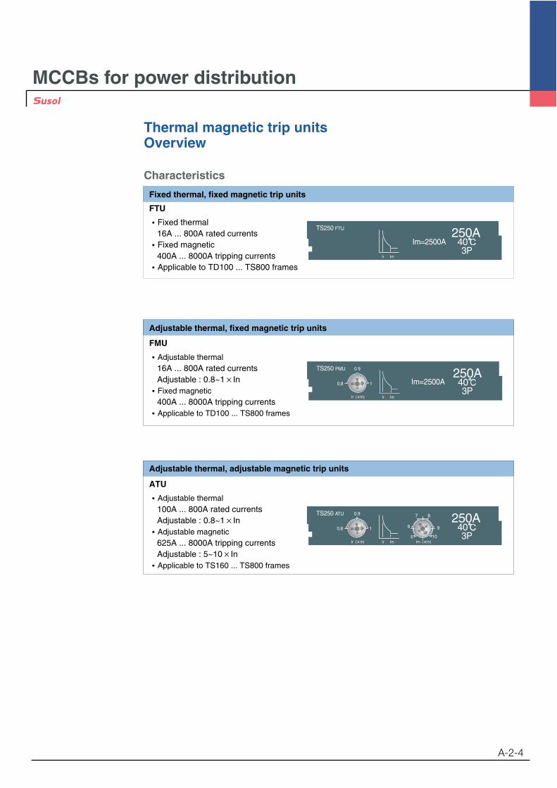
Thermal magnetic trip unitsOverview
Characteristics
FTU
Fixed thermal16A ... 800A rated currentsFixed magnetic400A ... 8000A tripping currentsApplicable to TD100 ... TS800 frames
Fixed thermal, fixed magnetic trip units
Im=2500A
TS250 FTU
Ir Im
FMU
Adjustable thermal16A ... 800A rated currentsAdjustable : 0.8~1 InFixed magnetic400A ... 8000A tripping currentsApplicable to TD100 ... TS800 frames
Adjustable thermal, fixed magnetic trip units
ATU
Adjustable thermal100A ... 800A rated currentsAdjustable : 0.8~1 InAdjustable magnetic625A ... 8000A tripping currentsAdjustable : 5~10 InApplicable to TS160 ... TS800 frames
Adjustable thermal, adjustable magnetic trip units
TS250 ATU
Ir Im
0.8
0.9
1
7 8
9
10
6
5

MCCBs for power distribution
A-2-5
Thermal magnetic trip unitsFTU, FMU for TD100, TD160
Configuration
Ratings (A), In at 40°C
Trip unit identification
TD160FTU
Im=1600A160A
Ir Im
t
Ir Im0 I
0.8
0.9
1
Number of pole
Overload protection (thermal)Setting current, Ir
Short circuit protection (magnetic)Setting current, Im
Trip unit function- FTU : Fixed thermal & magnetic unit- FMU : Adjustable thermal, fixed magnetic unit
MCCB frame type- TD100 : TD100N, TD100H, TD100L- TD160 : TD160N, TD160H, TD160L
TD160 FMU
TD100 FTU, TD160 FTU- Fixed thermal & magnetic trip unit TD100FMU, TD160 FMU
TD160FMU
0.8
0.9
1 Im=1600A160A
Ir Im
TD100 FMU, TD160 FMU- Adjustable thermal & fixed magnetic trip unit
Catalogue numbering system
MCCBs for power distribution
A-2-6
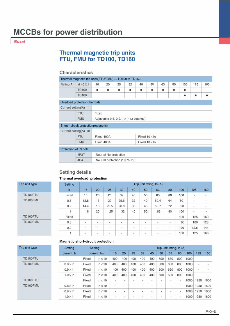
Thermal magnetic trip unitsFTU, FMU for TD100, TD160
Characteristics
Trip unit type
TD100FTU
TD100FMU
TD160FTU
TD160FMU
Setting Trip unit rating, In (A)
Ir 16 20 25 32 40 50 63 80 100 125 160
Fixed 16 20 25 32 40 50 63 80 100 - -
0.8 12.8 16 20 25.6 32 40 50.4 64 80 - -
0.9 14.4 18 22.5 28.8 36 45 56.7 72 90 - -
1 16 20 25 32 40 50 63 80 100 - -
Fixed - - - - - - - - 100 125 160
0.8 - - - - - - - - 80 100 128
0.9 - - - - - - - - 90 112.5 144
1 - - - - - - - - 100 125 160
Setting detailsThermal overload protection
Rating(A) at 40 In 16 20 25 32 40 50 63 80 100 125 160
TD100
TD160
Overload protection(thermal)
Current setting(A) Ir
FTU Fixed
FMU Adjustable 0.8, 0.9, 1 In (3 settings)
Short - circuit protection(magnetic)
Current setting(A) Im
FTU Fixed 400A Fixed 10 In
FMU Fixed 400A Fixed 10 In
Protection of N pole
4P3T Neutral No protection
4P4T Neutral protection (100% In)
Trip unit type
TD100FTU
TD100FMU
TD160FTU
TD160FMU
Setting Setting Trip unit rating, In (A)
current, Ir current, Im 16 20 25 32 40 50 63 80 100 125 160
Fixed In 10 400 400 400 400 400 500 630 800 1000 - -
0.8 In Fixed In 10 400 400 400 400 400 500 630 800 1000 - -
0.9 In Fixed In 10 400 400 400 400 400 500 630 800 1000 - -
1.0 In Fixed In 10 400 400 400 400 400 500 630 800 1000 - -
Fixed In 10 - - - - - - - - 1000 1250 1600
0.8 In Fixed In 10 - - - - - - - - 1000 1250 1600
0.9 In Fixed In 10 - - - - - - - - 1000 1250 1600
1.0 In Fixed In 10 - - - - - - - - 1000 1250 1600
Magnetic short-circuit protection
Thermal magnetic trip units(FTU/FMU) ... TD100 to TD160
MCCBs for power distribution
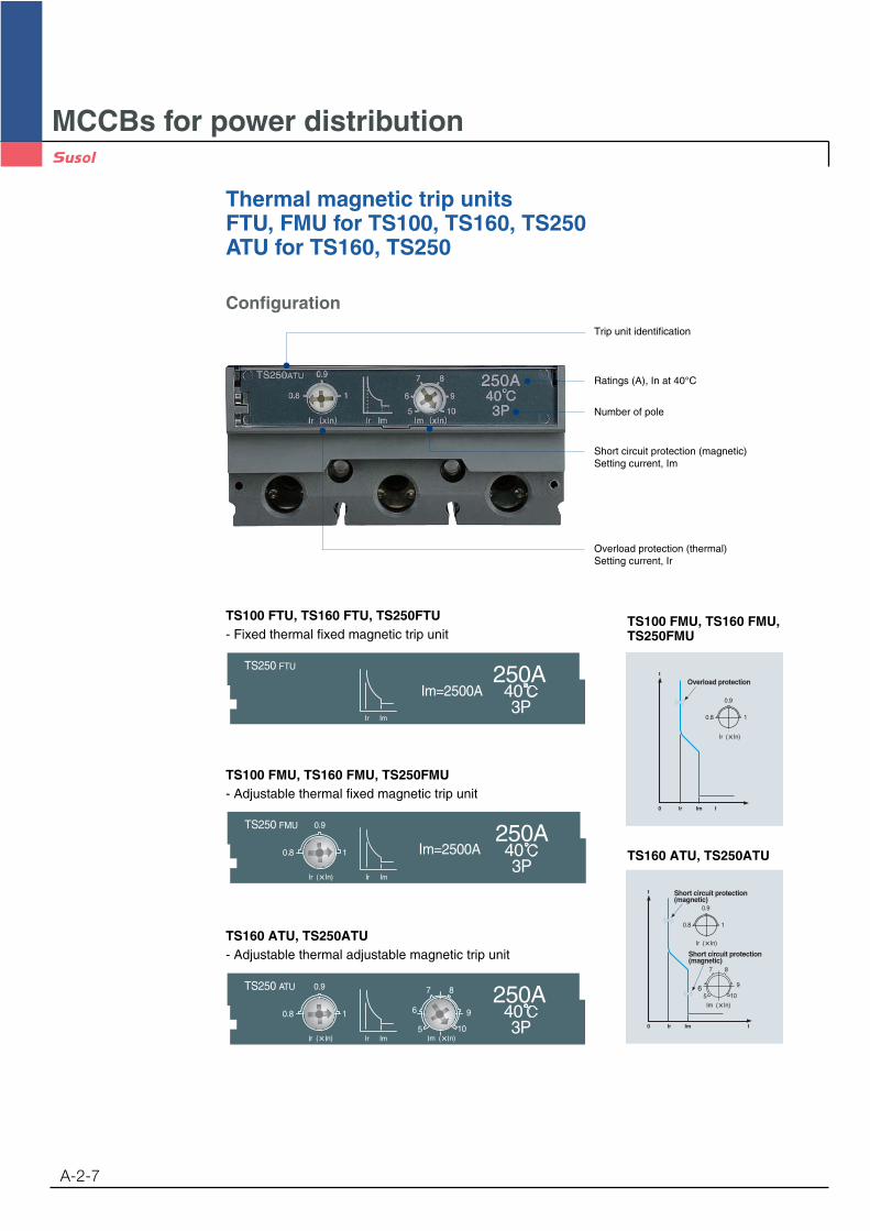
Thermal magnetic trip unitsFTU, FMU for TS100, TS160, TS250ATU for TS160, TS250
A-2-7
Im=2500A
TS250 FTU
Ir Im
TS100 FTU, TS160 FTU, TS250FTU- Fixed thermal fixed magnetic trip unit
TS100 FMU, TS160 FMU, TS250FMU
t
Ir Im0 I
0.8
0.9
1
7 8
9
106
5
Short circuit protection(magnetic)
Short circuit protection(magnetic)
TS160 ATU, TS250ATU
TS100 FMU, TS160 FMU, TS250FMU- Adjustable thermal fixed magnetic trip unit
TS250 ATU
Ir Im
0.8
0.9
1
7 8
9
10
6
5
TS160 ATU, TS250ATU- Adjustable thermal adjustable magnetic trip unit
Configuration
Ratings (A), In at 40°C
Trip unit identification
Number of pole
Overload protection (thermal)Setting current, Ir
Short circuit protection (magnetic)Setting current, Im
MCCBs for power distribution
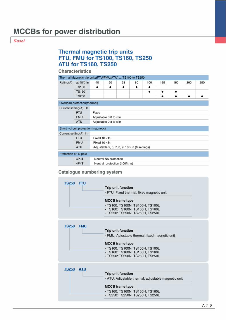
Thermal magnetic trip unitsFTU, FMU for TS100, TS160, TS250ATU for TS160, TS250
A-2-8
Trip unit function- FTU: Fixed thermal, fixed magnetic unit
MCCB frame type- TS100: TS100N, TS100H, TS100L- TS160: TS160N, TS160H, TS160L- TS250: TS250N, TS250H, TS250L
TS250 FTU
Trip unit function- FMU: Adjustable thermal, fixed magnetic unit
MCCB frame type- TS100: TS100N, TS100H, TS100L- TS160: TS160N, TS160H, TS160L- TS250: TS250N, TS250H, TS250L
TS250 FMU
Trip unit function- ATU: Adjustable thermal, adjustable magnetic unit
MCCB frame type- TS160: TS160N, TS160H, TS160L- TS250: TS250N, TS250H, TS250L
TS250 ATU
Catalogue numbering system
Characteristics
Overload protection(thermal)
Current setting(A) Ir
FTU Fixed
FMU Adjustable 0.8 to In
ATU Adjustable 0.8 to In
Short - circuit protection(magnetic)
Protection of N pole
4P3T Neutral No protection
4P4T Neutral protection (100% In)
Thermal Magnetic trip units(FTU/FMU/ATU) ... TS100 to TS250
Rating(A) at 40 In 40 50 63 80 100 125 160 200 250
TS100
TS160
TS250
Current setting(A) Im
FTU Fixed 10 In
FMU Fixed 10 In
ATU Adjustable 5, 6, 7, 8, 9, 10 In (6 settings)
MCCBs for power distribution
Thermal magnetic trip unitsFTU, FMU for TS100, TS160, TS250ATU for TS160, TS250
A-2-9
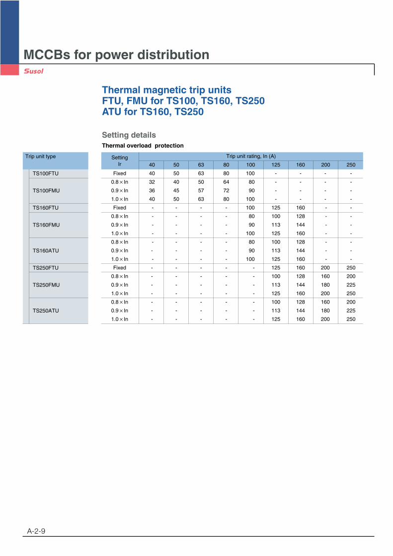
Setting detailsThermal overload protection
Trip unit type
TS100FTU
TS100FMU
TS160FTU
TS160FMU
TS160ATU
TS250FTU
TS250FMU
TS250ATU
Setting Trip unit rating, In (A)
Ir 40 50 63 80 100 125 160 200 250
Fixed 40 50 63 80 100 - - - -
0.8 In 32 40 50 64 80 - - - -
0.9 In 36 45 57 72 90 - - - -
1.0 In 40 50 63 80 100 - - - -
Fixed - - - - 100 125 160 - -
0.8 In - - - - 80 100 128 - -
0.9 In - - - - 90 113 144 - -
1.0 In - - - - 100 125 160 - -
0.8 In - - - - 80 100 128 - -
0.9 In - - - - 90 113 144 - -
1.0 In - - - - 100 125 160 - -
Fixed - - - - - 125 160 200 250
0.8 In - - - - - 100 128 160 200
0.9 In - - - - - 113 144 180 225
1.0 In - - - - - 125 160 200 250
0.8 In - - - - - 100 128 160 200
0.9 In - - - - - 113 144 180 225
1.0 In - - - - - 125 160 200 250

MCCBs for power distribution
Thermal magnetic trip unitsFTU, FMU for TS100, TS160, TS250ATU for TS160, TS250
A-2-10
Trip unit type
TS100FTU
TS100FMU
TS160FTU
TS160FMU
TS160ATU
TS250FTU
TS250FMU
TS250ATU
Setting Setting Trip unit rating, In (A)
current, Ir current, Im 40 50 63 80 100 125 160 200 250
Fixed In 10 400 500 630 800 1000 - - - -0.8 In Fixed In 10 400 500 630 800 1000 - - - -0.9 In Fixed In 10 400 500 630 800 1000 - - - -1.0 In Fixed In 10 400 500 630 800 1000 - - - -
Fixed In 10 - - - - 1000 1250 16000.8 In Fixed In 10 - - - - 1000 1250 1600 - -0.9 In Fixed In 10 - - - - 1000 1250 1600 - -1.0 In Fixed In 10 - - - - 1000 1250 1600 - -
In 5 - - - - 500 625 800 - -In 6 - - - - 600 750 960 - -
0.8 In AdjustableIn 7 - - - - 700 875 1120 - -In 8 - - - - 800 1000 1280 - -In 9 - - - - 900 1125 1440 - -
In 10 - - - - 1000 1250 1600 - -In 5 - - - - 500 625 800 - -In 6 - - - - 600 750 960 - -
0.9 In AdjustableIn 7 - - - - 700 875 1120 - -In 8 - - - - 800 1000 1280 - -In 9 - - - - 900 1125 1440 - -
In 10 - - - - 1000 1250 1600 - -In 5 - - - - 500 625 800 - -In 6 - - - - 600 750 960 - -
1.0 In AdjustableIn 7 - - - - 700 875 1120 - -In 8 - - - - 800 1000 1280 - -In 9 - - - - 900 1125 1440 - -
In 10 - - - - 1000 1250 1600 - -Fixed In 10 - - - - - 1250 1600 2000 2500
0.8 In Fixed In 10 - - - - - 1250 1600 2000 25000.9 In Fixed In 10 - - - - - 1250 1600 2000 25001.0 In Fixed In 10 - - - - - 1250 1600 2000 2500
In 5 - - - - - 625 800 1000 1250In 6 - - - - - 750 960 1200 1500
0.8 In AdjustableIn 7 - - - - - 875 1120 1400 1750In 8 - - - - - 1000 1280 1600 2000In 9 - - - - - 1125 1440 1800 2250
In 10 - - - - - 1250 1600 2000 2500In 5 - - - - - 625 800 1000 1250In 6 - - - - - 750 960 1200 1500
0.9 In AdjustableIn 7 - - - - - 875 1120 1400 1750In 8 - - - - - 1000 1280 1600 2000In 9 - - - - - 1125 1440 1800 2250
In 10 - - - - - 1250 1600 2000 2500In 5 - - - - - 625 800 1000 1250In 6 - - - - - 750 960 1200 1500
1.0 In AdjustableIn 7 - - - - - 875 1120 1400 1750In 8 - - - - - 1000 1280 1600 2000In 9 - - - - - 1125 1440 1800 2250
In 10 - - - - - 1250 1600 2000 2500
Setting detailsMagnetic short-circuit protection
MCCBs for power distribution
Thermal magnetic trip unitsFTU, FMU, ATU for TS400, TS630
A-2-11
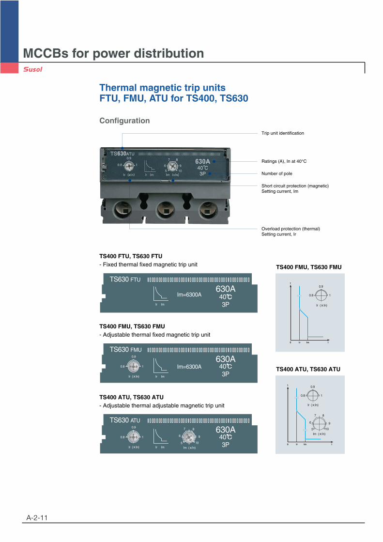
TS630 FTU
630AIm=6300A
Ir Im
t
Ir Im0 I
0.8
0.9
1
TS400 FTU, TS630 FTU- Fixed thermal fixed magnetic trip unit TS400 FMU, TS630 FMU
t
Ir Im0 I
0.8
0.9
1
7 8
9
10
6
5
TS400 ATU, TS630 ATUIm=6300A
TS630 FMU
630A
Ir Im
0.8
0.9
1
TS400 FMU, TS630 FMU- Adjustable thermal fixed magnetic trip unit
TS630 ATU
630A
Ir Im
0.8
0.9
1
7 8
9
10
6
5
TS400 ATU, TS630 ATU- Adjustable thermal adjustable magnetic trip unit
Configuration
Ratings (A), In at 40°C
Trip unit identification
Number of pole
Overload protection (thermal)Setting current, Ir
Short circuit protection (magnetic)Setting current, Im
MCCBs for power distribution
Thermal magnetic trip unitsFTU, FMU, ATU for TS400, TS630
A-2-12
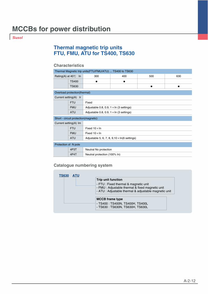
CharacteristicsThermal Magnetic trip units(FTU/FMU/ATU) ... TS400 to TS630
Rating(A) at 40 In 300 400 500 630
TS400
TS630
Overload protection(thermal)
Current setting(A) Ir
FTU Fixed
FMU Adjustable 0.8, 0.9, 1 In (3 settings)
ATU Adjustable 0.8, 0.9, 1 In (3 settings)
Short - circuit protection(magnetic)
Current setting(A) Im
FTU Fixed 10 In
FMU Fixed 10 In
ATU Adjustable 5, 6, 7, 8, 9,10 In(6 settings)
Protection of N pole
4P3T Neutral No protection
4P4T Neutral protection (100% In)
Trip unit function- FTU : Fixed thermal & magnetic unit- FMU : Adjustable thermal & fixed magnetic unit- ATU : Adjustable thermal & adjustable magnetic unit
MCCB frame type- TS400 : TS400N, TS400H, TS400L- TS630 : TS630N, TS630H, TS630L
TS630 ATU
Catalogue numbering system
MCCBs for power distribution
Thermal magnetic trip unitsFTU, FMU, ATU for TS400, TS630
A-2-13
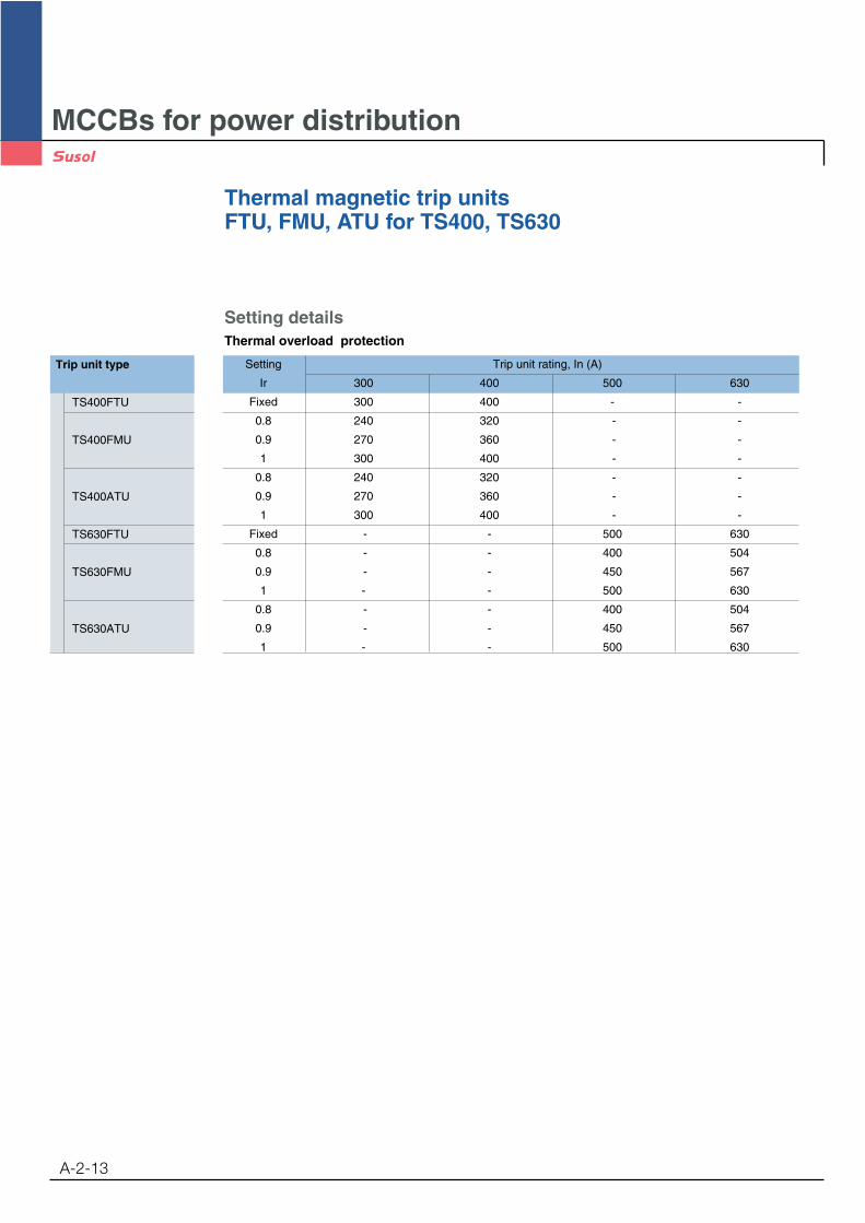
Setting detailsThermal overload protection
Trip unit type
TS400FTU
TS400FMU
TS400ATU
TS630FTU
TS630FMU
TS630ATU
Setting Trip unit rating, In (A)
Ir 300 400 500 630
Fixed 300 400 - -
0.8 240 320 - -
0.9 270 360 - -
1 300 400 - -
0.8 240 320 - -
0.9 270 360 - -
1 300 400 - -
Fixed - - 500 630
0.8 - - 400 504
0.9 - - 450 567
1 - - 500 630
0.8 - - 400 504
0.9 - - 450 567
1 - - 500 630

MCCBs for power distribution
Thermal magnetic trip unitsFTU, FMU, ATU for TS400, TS630
A-2-14
Trip unit type
TS400FTU
TS400FMU
TS400ATU
TS630FTU
TS630FMU
TS630ATU
Setting Setting Trip unit rating, In (A)
current, Ir current, Im 300 400 500 630
Fixed In 10 3000 4000 - -0.8 In Fixed In 10 3000 4000 - -0.9 In Fixed In 10 3000 4000 - -1.0 In Fixed In 10 3000 4000 - -
In 5 1500 2000 - -In 6 1800 2400 - -
0.8 In AdjustableIn 7 2100 2800 - -In 8 2400 3200 - -In 9 2700 3600 - -
In 10 3000 4000 - -In 5 1500 2000 - -In 6 1800 2400 - -
0.9 In AdjustableIn 7 2100 2800 - -In 8 2400 3200 - -In 9 2700 3600 - -
In 10 3000 4000 - -In 5 1500 2000 - -In 6 1800 2400 - -
1.0 In AdjustableIn 7 2100 2800 - -In 8 2400 3200 - -In 9 2700 3600 - -
In 10 3000 4000 - -Fixed In 10 - - 5000 6300
0.8 In Fixed In 10 - - 5000 63000.9 In Fixed In 10 - - 5000 63001.0 In Fixed In 10 - - 5000 6300
In 5 - - 2500 3150In 6 - - 3000 3780
0.8 In AdjustableIn 7 - - 3500 4410In 8 - - 4000 5040In 9 - - 4500 5670
In 10 - - 5000 6300In 5 - - 2500 3150In 6 - - 3000 3780
0.9 In AdjustableIn 7 - - 3500 4410In 8 - - 4000 5040In 9 - - 4500 5670
In 10 - - 5000 6300In 5 - - 2500 3150In 6 - - 3000 3780
1.0 In AdjustableIn 7 - - 3500 4410In 8 - - 4000 5040In 9 - - 4500 5670
In 10 - - 5000 6300
Setting detailsMagnetic short-circuit protection
MCCBs for power distribution
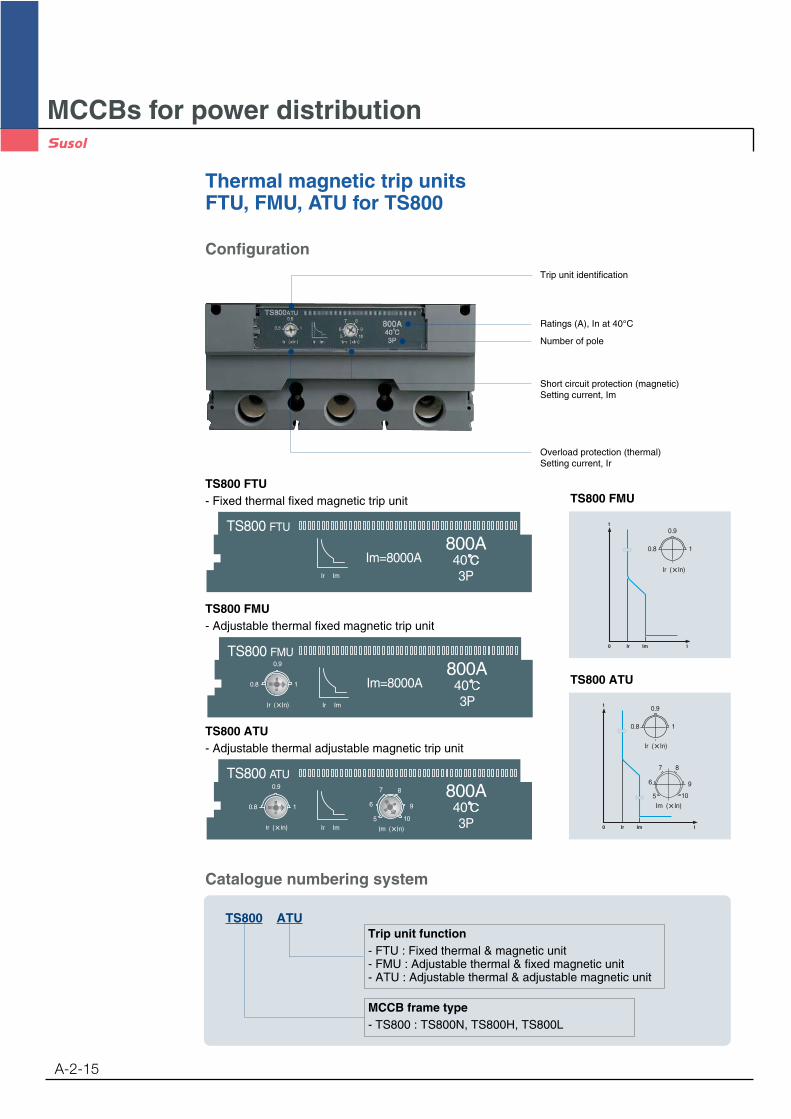
Thermal magnetic trip unitsFTU, FMU, ATU for TS800
A-2-15
TS800 FTU
800AIm=8000A
Ir Im
t
Ir Im0 I
0.8
0.9
1
TS800 FTU- Fixed thermal fixed magnetic trip unit TS800 FMU
t
Ir Im0 I
0.8
0.9
1
7 8
9
10
6
5
TS800 ATU
Ir Im
0.8
0.9
1
TS800 FMU
800AIm=8000A
TS800 FMU- Adjustable thermal fixed magnetic trip unit
Ir Im
0.8
0.9
1
7 8
9
10
6
5
TS800 ATU
800A
TS800 ATU- Adjustable thermal adjustable magnetic trip unit
Trip unit function- FTU : Fixed thermal & magnetic unit- FMU : Adjustable thermal & fixed magnetic unit- ATU : Adjustable thermal & adjustable magnetic unit
MCCB frame type- TS800 : TS800N, TS800H, TS800L
TS800 ATU
Catalogue numbering system
Configuration
Ratings (A), In at 40°C
Trip unit identification
Number of pole
Overload protection (thermal)Setting current, Ir
Short circuit protection (magnetic)Setting current, Im
Thermal magnetic trip unitsFTU, FMU, ATU for TS800
A-2-16
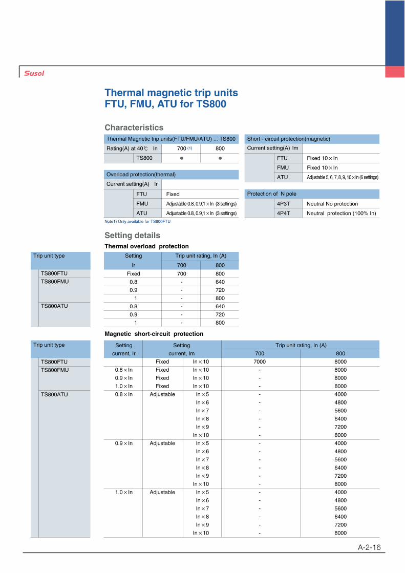
Characteristics
Overload protection(thermal)
Current setting(A) Ir
FTU Fixed
FMU Adjustable 0.8, 0.9,1 In (3 settings)
ATU Adjustable 0.8, 0.9,1 In (3 settings)
Short - circuit protection(magnetic)
Current setting(A) Im
FTU Fixed 10 In
FMU Fixed 10 In
ATU Adjustable 5, 6, 7, 8, 9, 10 In (6 settings)
Thermal Magnetic trip units(FTU/FMU/ATU) ... TS800
Rating(A) at 40 In 700 800
TS800
Protection of N pole
4P3T Neutral No protection
4P4T Neutral protection (100% In)
Trip unit type
TS800FTU
TS800FMU
TS800ATU
Setting Trip unit rating, In (A)
Ir 700 800
Fixed 700 800
0.8 - 640
0.9 - 720
1 - 800
0.8 - 640
0.9 - 720
1 - 800
Setting detailsThermal overload protection
Trip unit type
TS800FTU
TS800FMU
TS800ATU
Setting Setting Trip unit rating, In (A)
current, Ir current, Im 700 800
Fixed In 10 7000 8000
0.8 In Fixed In 10 - 8000
0.9 In Fixed In 10 - 8000
1.0 In Fixed In 10 - 8000
0.8 In Adjustable In 5 - 4000
In 6 - 4800
In 7 - 5600
In 8 - 6400
In 9 - 7200
In 10 - 8000
0.9 In Adjustable In 5 - 4000
In 6 - 4800
In 7 - 5600
In 8 - 6400
In 9 - 7200
In 10 - 8000
1.0 In Adjustable In 5 - 4000
In 6 - 4800
In 7 - 5600
In 8 - 6400
In 9 - 7200
In 10 - 8000
Magnetic short-circuit protection
Note1) Only available for TS800FTU
(1)

MCCBs for power distribution
Overview of electronic trip units (Standard type)
A-2-17
Types: ETS23, ETS33, ETS43
3 frame size of circuit breaker: 250AF, 630AF, 800AF
Only three(3) pole circuit breakers are available.
The Trip units can be mounted on circuit breakers of N, H and L type from TS100 to TS800.
Test connector for trip unit (AC/DC 30mA ~ AC/DC 100mA)
ProtectionOverload protectionShort-circuit protection
Overload protection (long time)
Setting current (A), Ir 0.4, 0.45, 0.5, 0.55, 0.6, 0.65, 0.7, 0.75, 0.8, 0.85, 0.9, 0.95, 1.0 In,
13 setting
Tripping time (s) Fixed at 6 Ir , tolerance 20%
ETS
ETS23 for TS100N/H/L
ETS23 for TS160N/H/L
ETS23 for TS250N/H/L
ETS33 for TS400N/H/L
ETS33 for TS630N/H/L
ETS43 for TS800N/H/L
16 32 40 64 80 100 160 250 320 400 630 800
Current setting, Ir(A)
RatingsTrip units
ETS23 ETS33 ETS43
TS100 N/H/L TS160 N/H/L TS250 N/H/L TS400 N/H/L TS630 N/H/L TS800 N/H/L
Setting values
Short-circuit protection (short time)
Tripping threshold (A), Isd adjustable 1.5, 2, 3, 4, 5, 6, 7, 8, 10 Ir, 9 setting, tolerance 15%
Time delay (ms) adjustable 50, 100, 200, 300, 4 setting, tolerance 20%
Short circuit protection (Instantaneous)
Tripping threshold (A), Ii Fixed at 11 In
Rated 40
current, 80
In (A) 160
250
400
630
800
Applicable to

MCCBs for power distribution
Overview of electronic trip units (Standard type)
A-2-18
ETS2390%105%
alarm
TEST
In 250A
+ -
tsd
Ir Isd
.6
.5
.4
.7.8
.9
1.0
.3
.3
.2
.1
.05
tsd
4
3
2
1.5
56
7
810
ETS23 for TS100/TS160/TS250
ETS33
In 630ATEST+ -
.6
.5
.4
.7.8
.9
1.0
.3
.3
.2
.1
.05tsd
4
3
2
1.5
56
7
810
90%105%
alarm
tsd
tr
Ir Isd Ii
ETS33 for TS400/TS630
ETS43
In 800A
.6
.5
.4
.7.8
.9
1.0
.3
.3
.2
.1
.05tsd
4
3
2
1.5
56
7
810
90%105%
alarm
TEST+ -
ETS43 for TS800
Adjustable rated currentsetting (Ir)
Adjustable short timedelay current setting (Isd)
Adjustable time delaysetting (tsd)
Alarm LED 90% Ir: ON, 105% Ir or more: ON-OFFTest connector
t
tsd
Ir Isd Ii I

MCCBs for power distribution
Electronic trip units (Standard)ETS23 for TS100, TS160, TS250
A-2-19
Trip unit frame- 23 for TS100, TS160, TS250- 33 for TS400, TS630- 43 for TS800
Rated current, In- 40, 80A for TS100- 40, 80, 160A for TS160- 40, 80, 160, 250A for TS250
Trip unit function- ETS: Standard electronic trip unit
ETS 23 In250A
Catalogue numbering system
ConfigurationElectronic type, ETS23 for MCCBs TS100, TS160, TS250
Trip unit identification
Indication of alarmLoad: not less than 90% Ir LED ONLoad: not less than 105% Ir LED flickering
Trip unit rating, In
Overload protection (long time)
Short time tripping delay
Short circuit protection (short time)
Test connector
t
tr
tsd
Ir
Io
td
tsd
Isd Ii Icu I
.6
.5
.4
.7.8
.9
1.0
.3
.3
.2
.1
.05
tsd
4
3
2
56
7
8
1.5 10
Overload protection(long time)
Short circuit protection(short time)
Short time trippingdelay
Overload protection (long time)
Short-circuit protection (short time)
Short circuit protection (Instantaneous)
Tripping threshold (A), Ii Fixed at 11 In
0.4, 0.45, 0.5, 0.55, 0.6, 0.65, 0.7,
Setting current (A), Ir 0.75, 0.8, 0.85, 0.9, 0.95, 1.0 In
13 settings
Tripping time (s) Fixed at 6 Ir , tolerance 20%
Tripping threshold (A),1.5, 2, 3, 4, 5, 6, 7, 8, 10 Ir
Isd9 settings
tolerance 15%
adjustable 50, 100, 200, 300
Time delay (ms) 4 settings
tolerance 20%
MCCBs for power distribution
Electronic trip units (Standard)ETS23 for TS100, TS160, TS250
A-2-20
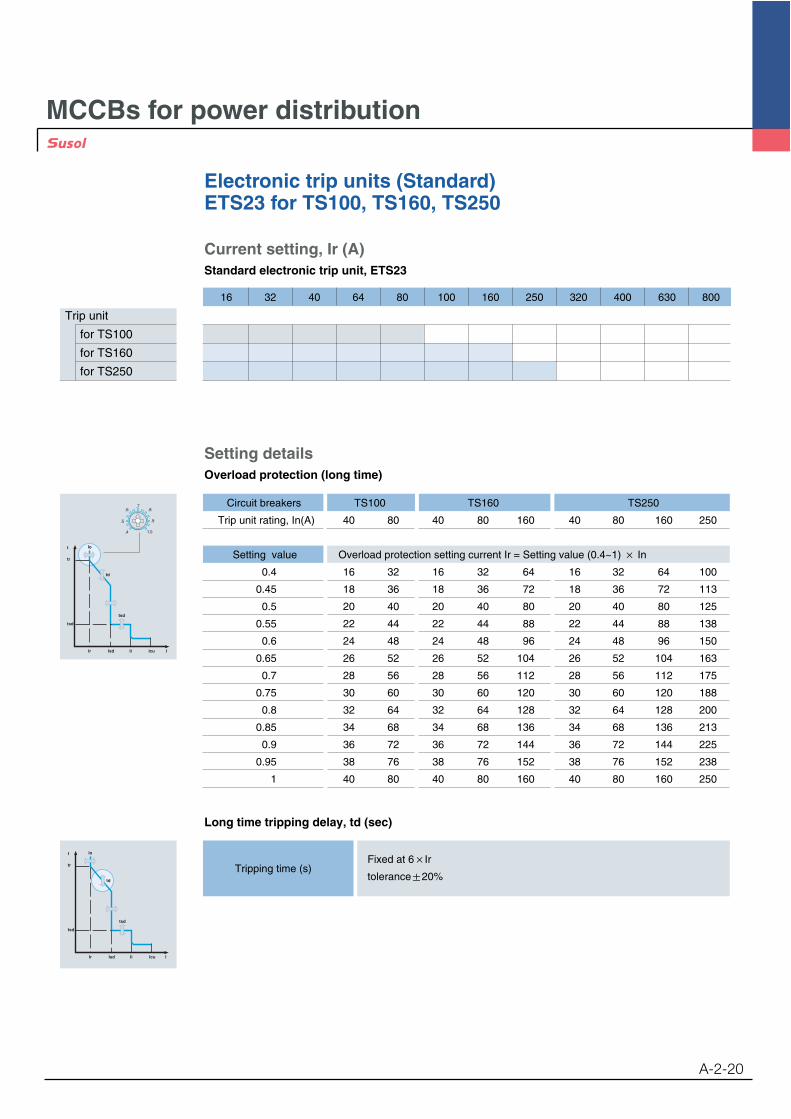
Setting detailsOverload protection (long time)
Current setting, Ir (A)Standard electronic trip unit, ETS23
16 32 40 64 80 100 160 250 320 400 630 800
Trip unit
for TS100
for TS160
for TS250
t
tr
tsd
Ir
Io
td
tsd
Isd Ii Icu I
.6
.5
.4
.7.8
.9
1.0
Circuit breakers TS100 TS160 TS250
Trip unit rating, In(A) 40 80 40 80 160 40 80 160 250
Setting value Overload protection setting current Ir = Setting value (0.4~1) In
0.4 16 32 16 32 64 16 32 64 100
0.45 18 36 18 36 72 18 36 72 113
0.5 20 40 20 40 80 20 40 80 125
0.55 22 44 22 44 88 22 44 88 138
0.6 24 48 24 48 96 24 48 96 150
0.65 26 52 26 52 104 26 52 104 163
0.7 28 56 28 56 112 28 56 112 175
0.75 30 60 30 60 120 30 60 120 188
0.8 32 64 32 64 128 32 64 128 200
0.85 34 68 34 68 136 34 68 136 213
0.9 36 72 36 72 144 36 72 144 225
0.95 38 76 38 76 152 38 76 152 238
1 40 80 40 80 160 40 80 160 250
Long time tripping delay, td (sec)
Tripping time (s)Fixed at 6 Ir
tolerance 20%
t
tr
tsd
Ir
Io
td
tsd
Isd Ii Icu I
MCCBs for power distribution
Electronic trip units (Standard)ETS23 for TS100, TS160, TS250
A-2-21
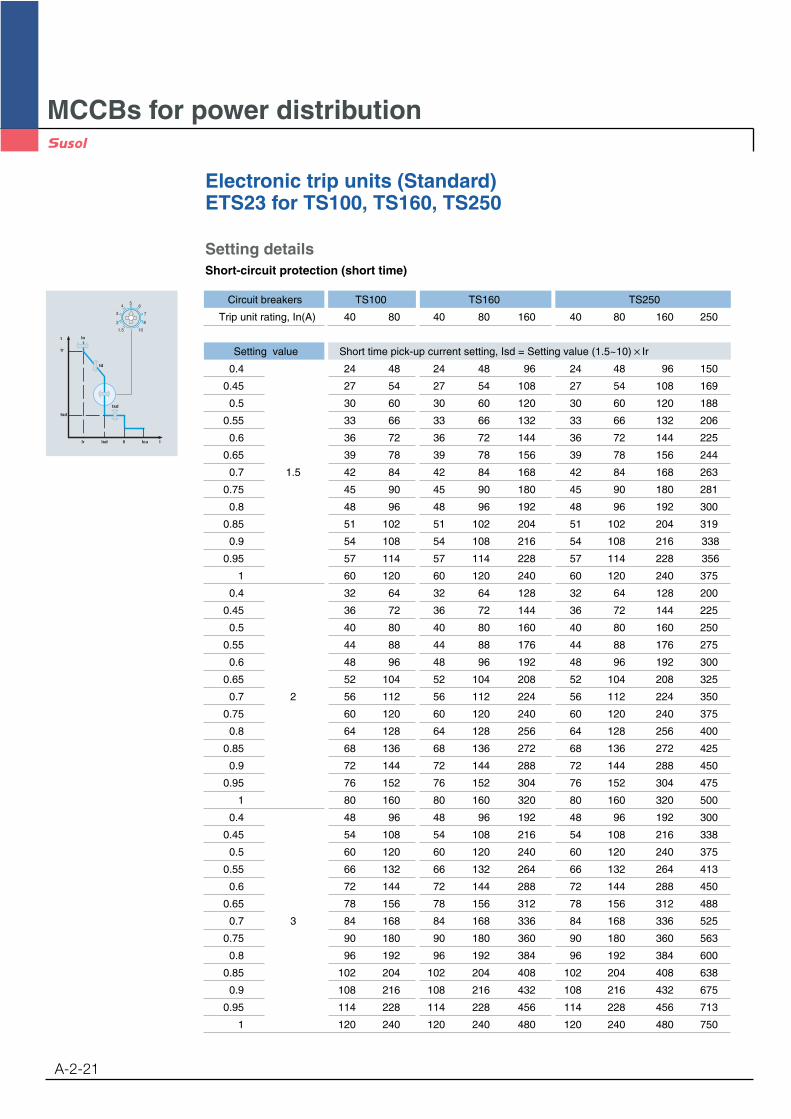
Setting detailsShort-circuit protection (short time)
t
tr
tsd
Ir
Io
td
tsd
Isd Ii Icu I
4
3
2
56
7
8
1.5 10
Circuit breakers TS100 TS160 TS250
Trip unit rating, In(A) 40 80 40 80 160 40 80 160 250
Setting value Short time pick-up current setting, Isd = Setting value (1.5~10) Ir
0.4 24 48 24 48 96 24 48 96 150
0.45 27 54 27 54 108 27 54 108 169
0.5 30 60 30 60 120 30 60 120 188
0.55 33 66 33 66 132 33 66 132 206
0.6 36 72 36 72 144 36 72 144 225
0.65 39 78 39 78 156 39 78 156 244
0.7 1.5 42 84 42 84 168 42 84 168 263
0.75 45 90 45 90 180 45 90 180 281
0.8 48 96 48 96 192 48 96 192 300
0.85 51 102 51 102 204 51 102 204 319
0.9 54 108 54 108 216 54 108 216 338
0.95 57 114 57 114 228 57 114 228 356
1 60 120 60 120 240 60 120 240 375
0.4 32 64 32 64 128 32 64 128 200
0.45 36 72 36 72 144 36 72 144 225
0.5 40 80 40 80 160 40 80 160 250
0.55 44 88 44 88 176 44 88 176 275
0.6 48 96 48 96 192 48 96 192 300
0.65 52 104 52 104 208 52 104 208 325
0.7 2 56 112 56 112 224 56 112 224 350
0.75 60 120 60 120 240 60 120 240 375
0.8 64 128 64 128 256 64 128 256 400
0.85 68 136 68 136 272 68 136 272 425
0.9 72 144 72 144 288 72 144 288 450
0.95 76 152 76 152 304 76 152 304 475
1 80 160 80 160 320 80 160 320 500
0.4 48 96 48 96 192 48 96 192 300
0.45 54 108 54 108 216 54 108 216 338
0.5 60 120 60 120 240 60 120 240 375
0.55 66 132 66 132 264 66 132 264 413
0.6 72 144 72 144 288 72 144 288 450
0.65 78 156 78 156 312 78 156 312 488
0.7 3 84 168 84 168 336 84 168 336 525
0.75 90 180 90 180 360 90 180 360 563
0.8 96 192 96 192 384 96 192 384 600
0.85 102 204 102 204 408 102 204 408 638
0.9 108 216 108 216 432 108 216 432 675
0.95 114 228 114 228 456 114 228 456 713
1 120 240 120 240 480 120 240 480 750

MCCBs for power distribution
Electronic trip units (Standard)ETS23 for TS100, TS160, TS250
A-2-22
t
tr
tsd
Ir
Io
td
tsd
Isd Ii Icu I
4
3
2
56
7
8
1.5 10
Circuit breakers TS100 TS160 TS250
Trip unit rating, In(A) 40 80 40 80 160 40 80 160 250
Setting value Short time pick-up current setting, Isd = Setting value (1.5~10) Ir
0.4 64 128 64 128 256 64 128 256 400
0.45 72 144 72 144 288 72 144 288 450
0.5 80 160 80 160 320 80 160 320 500
0.55 88 176 88 176 352 88 176 352 550
0.6 96 192 96 192 384 96 192 384 600
0.65 104 208 104 208 416 104 208 416 650
0.7 4 112 224 112 224 448 112 224 448 700
0.75 120 240 120 240 480 120 240 480 750
0.8 128 256 128 256 512 128 256 512 800
0.85 136 272 136 272 544 136 272 544 850
0.9 144 288 144 288 576 144 288 576 900
0.95 152 304 152 304 608 152 304 608 950
1 160 320 160 320 640 160 320 640 1000
0.4 80 160 80 160 320 80 160 320 500
0.45 90 180 90 180 360 90 180 360 563
0.5 100 200 100 200 400 100 200 400 625
0.55 110 220 110 220 440 110 220 440 688
0.6 120 240 120 240 480 120 240 480 750
0.65 130 260 130 260 520 130 260 520 813
0.7 5 140 280 140 280 560 140 280 560 875
0.75 150 300 150 300 600 150 300 600 938
0.8 160 320 160 320 640 160 320 640 1000
0.85 170 340 170 340 680 170 340 680 1063
0.9 180 360 180 360 720 180 360 720 1125
0.95 190 380 190 380 760 190 380 760 1188
1 200 400 200 400 800 200 400 800 1250
0.4 96 192 96 192 384 96 192 384 600
0.45 108 216 108 216 432 108 216 432 675
0.5 120 240 120 240 480 120 240 480 750
0.55 132 264 132 264 528 132 264 528 825
0.6 144 288 144 288 576 144 288 576 900
0.65 156 312 156 312 624 156 312 624 975
0.7 6 168 336 168 336 672 168 336 672 1050
0.75 180 360 180 360 720 180 360 720 1125
0.8 192 384 192 384 768 192 384 768 1200
0.85 204 408 204 408 816 204 408 816 1275
0.9 216 432 216 432 864 216 432 864 1350
0.95 228 456 228 456 912 228 456 912 1425
1 240 480 240 480 960 240 480 960 1500
MCCBs for power distribution
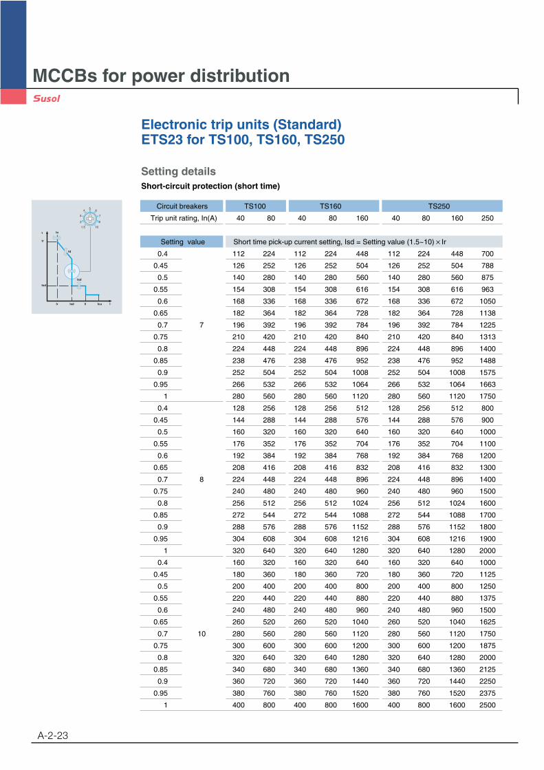
Electronic trip units (Standard)ETS23 for TS100, TS160, TS250
A-2-23
Setting detailsShort-circuit protection (short time)
t
tr
tsd
Ir
Io
td
tsd
Isd Ii Icu I
4
3
2
56
7
8
1.5 10
Circuit breakers TS100 TS160 TS250
Trip unit rating, In(A) 40 80 40 80 160 40 80 160 250
Setting value Short time pick-up current setting, Isd = Setting value (1.5~10) Ir
0.4 112 224 112 224 448 112 224 448 700
0.45 126 252 126 252 504 126 252 504 788
0.5 140 280 140 280 560 140 280 560 875
0.55 154 308 154 308 616 154 308 616 963
0.6 168 336 168 336 672 168 336 672 1050
0.65 182 364 182 364 728 182 364 728 1138
0.7 7 196 392 196 392 784 196 392 784 1225
0.75 210 420 210 420 840 210 420 840 1313
0.8 224 448 224 448 896 224 448 896 1400
0.85 238 476 238 476 952 238 476 952 1488
0.9 252 504 252 504 1008 252 504 1008 1575
0.95 266 532 266 532 1064 266 532 1064 1663
1 280 560 280 560 1120 280 560 1120 1750
0.4 128 256 128 256 512 128 256 512 800
0.45 144 288 144 288 576 144 288 576 900
0.5 160 320 160 320 640 160 320 640 1000
0.55 176 352 176 352 704 176 352 704 1100
0.6 192 384 192 384 768 192 384 768 1200
0.65 208 416 208 416 832 208 416 832 1300
0.7 8 224 448 224 448 896 224 448 896 1400
0.75 240 480 240 480 960 240 480 960 1500
0.8 256 512 256 512 1024 256 512 1024 1600
0.85 272 544 272 544 1088 272 544 1088 1700
0.9 288 576 288 576 1152 288 576 1152 1800
0.95 304 608 304 608 1216 304 608 1216 1900
1 320 640 320 640 1280 320 640 1280 2000
0.4 160 320 160 320 640 160 320 640 1000
0.45 180 360 180 360 720 180 360 720 1125
0.5 200 400 200 400 800 200 400 800 1250
0.55 220 440 220 440 880 220 440 880 1375
0.6 240 480 240 480 960 240 480 960 1500
0.65 260 520 260 520 1040 260 520 1040 1625
0.7 10 280 560 280 560 1120 280 560 1120 1750
0.75 300 600 300 600 1200 300 600 1200 1875
0.8 320 640 320 640 1280 320 640 1280 2000
0.85 340 680 340 680 1360 340 680 1360 2125
0.9 360 720 360 720 1440 360 720 1440 2250
0.95 380 760 380 760 1520 380 760 1520 2375
1 400 800 400 800 1600 400 800 1600 2500
MCCBs for power distribution
Electronic trip units (Standard)ETS23 for TS100, TS160, TS250
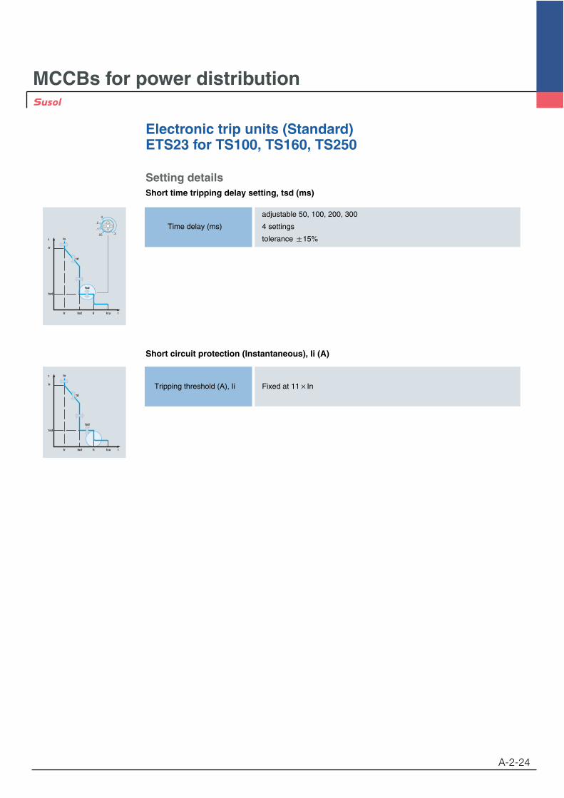
A-2-24
Setting detailsShort time tripping delay setting, tsd (ms)
adjustable 50, 100, 200, 300
Time delay (ms) 4 settings
tolerance 15%t
tr
tsd
Ir
Io
td
tsd
Isd Ii Icu I
.3
.3
.2
.1
.05
Short circuit protection (Instantaneous), Ii (A)
Tripping threshold (A), Ii Fixed at 11 In
t
tr
tsd
Ir
Io
td
tsd
Isd Ii Icu I

MCCBs for power distribution
Electronic trip units (Standard)ETS33 for TS400, TS630
A-2-25
Trip unit frame- 23 for TS100, TS160, TS250- 33 for TS400, TS630- 43 for TS800
Rated current, In- 160, 250, 400A for TS400- 160, 250, 400, 630A for
TS630
Trip unit function- ETS: Standard electronic trip unit
ETS 33 In630A
Catalogue numbering system
ConfigurationElectronic type, ETS33 for MCCBs TS400 & TS630
Trip unit identification
Indication of alarmLoad: not less than 90% Ir LED ONLoad: not less than 105% Ir LED flickering
Trip unit rating, In
Test connector
Short time tripping delay
Overload protection (long time)
Short-circuit protection (short time)
t
tr
tsd
Ir
Io
td
tsd
Isd Ii Icu I
.6
.5
.4
.7.8
.9
1.0
.3
.3
.2
.1
.05
tsd
4
3
2
56
7
8
1.5 10
Overload protection(long time)
Short circuit protection(short time)
Short time trippingdelay
Overload protection (long time)
Short circuit protection (Instantaneous)
Tripping threshold (A), Ii Fixed at 11 In
0.4, 0.45, 0.5, 0.55, 0.6, 0.65, 0.7,
Setting current (A), Ir 0.75, 0.8, 0.85, 0.9, 0.95, 1.0 In
13 settings
Tripping time (s) Fixed at 6 Ir , tolerance 20%
Tripping threshold (A),1.5, 2, 3, 4, 5, 6, 7, 8, 10 Ir
Isd9 settings
tolerance 15%
adjustable 50, 100, 200, 300
Time delay (ms) 4 settings
tolerance 20%
Short-circuit protection (short time)

MCCBs for power distribution
Electronic trip units (Standard)ETS33 for TS400, TS630
A-2-26
t
tr
tsd
Ir
Io
td
tsd
Isd Ii Icu I
.6
.5
.4
.7.8
.9
1.0
Long time tripping delay, td (sec)
Tripping time (s)Fixed at 6 Ir
tolerance 20%
t
tr
tsd
Ir
Io
td
tsd
Isd Ii Icu I
Trip unit
for TS400
for TS630
Current setting, Ir (A)Standard electronic trip unit, ETS33
16 32 40 64 80 100 160 250 320 400 630 800
Setting detailsOverload protection (long time)
Circuit breakers TS400 TS630
Trip unit rating, In(A) 160 250 400 160 250 400 630
Setting value Overload protection setting current Ir = Setting value (0.4~1) In
0.4 64 100 160 64 100 160 252
0.45 72 113 180 72 113 180 284
0.5 80 125 200 80 125 200 315
0.55 88 138 220 88 138 220 347
0.6 96 150 240 96 150 240 378
0.65 104 163 260 104 163 260 410
0.7 112 175 280 112 175 280 441
0.75 120 188 300 120 188 300 473
0.8 128 200 320 128 200 320 504
0.85 136 213 340 136 213 340 536
0.9 144 225 360 144 225 360 567
0.95 152 238 380 152 238 380 599
1 160 250 400 160 250 400 630

MCCBs for power distribution
Electronic trip units (Standard)ETS33 for TS400, TS630
A-2-27
Setting detailsShort-circuit protection (short time)
t
tr
tsd
Ir
Io
td
tsd
Isd Ii Icu I
4
3
2
56
7
8
1.5 10
Circuit breakers TS400 TS630
Trip unit rating, In(A) 160 250 400 160 250 400 630
Setting value Short time pick-up current setting, Isd = Setting value (1.5~10) Ir
0.4 96 150 240 96 150 240 378
0.45 108 169 270 108 169 270 425
0.5 120 188 300 120 188 300 473
0.55 132 206 330 132 206 330 520
0.6 144 225 360 144 225 360 567
0.65 156 244 390 156 244 390 614
0.7 1.5 168 263 420 168 263 420 662
0.75 180 281 450 180 281 450 709
0.8 192 300 480 192 300 480 756
0.85 204 319 510 204 319 510 803
0.9 216 338 540 216 338 540 851
0.95 228 356 570 228 356 570 898
1 240 375 600 240 375 600 945
0.4 128 200 320 128 200 320 504
0.45 144 225 360 144 225 360 567
0.5 160 250 400 160 250 400 630
0.55 176 275 440 176 275 440 693
0.6 192 300 480 192 300 480 756
0.65 208 325 520 208 325 520 819
0.7 2 224 350 560 224 350 560 882
0.75 240 375 600 240 375 600 945
0.8 256 400 640 256 400 640 1008
0.85 272 425 680 272 425 680 1071
0.9 288 450 720 288 450 720 1134
0.95 304 475 760 304 475 760 1197
1 320 500 800 320 500 800 1260
0.4 192 300 480 192 300 480 756
0.45 216 338 540 216 338 540 851
0.5 240 375 600 240 375 600 945
0.55 264 413 660 264 413 660 1040
0.6 288 450 720 288 450 720 1134
0.65 312 488 780 312 488 780 1229
0.7 3 336 525 840 336 525 840 1323
0.75 360 563 900 360 563 900 1418
0.8 384 600 960 384 600 960 1512
0.85 408 638 1020 408 638 1020 1607
0.9 432 675 1080 432 675 1080 1701
0.95 456 713 1140 456 713 1140 1795
1 480 750 1200 480 750 1200 1890
MCCBs for power distribution
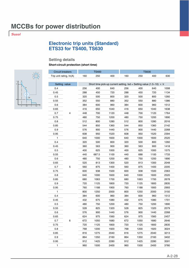
Electronic trip units (Standard)ETS33 for TS400, TS630
A-2-28
Setting detailsShort-circuit protection (short time)
Circuit breakers TS400 TS630
Trip unit rating, In(A) 160 250 400 160 250 400 630
Setting value Short time pick-up current setting, Isd = Setting value (1.5~10) Ir
0.4 256 400 640 256 400 640 1008
0.45 288 450 720 288 450 720 1134
0.5 320 500 800 320 500 800 1260
0.55 352 550 880 352 550 880 1386
0.6 384 600 960 384 600 960 1512
0.65 416 650 1040 416 650 1040 1638
0.7 4 448 700 1120 448 700 1120 1764
0.75 480 750 1200 480 750 1200 1890
0.8 512 800 1280 512 800 1280 2016
0.85 544 850 1360 544 850 1360 2142
0.9 576 900 1440 576 900 1440 2268
0.95 608 950 1520 608 950 1520 2394
1 640 1000 1600 640 1000 1600 2520
0.4 320 500 800 320 500 800 1260
0.45 360 563 900 360 563 900 1418
0.5 400 625 1000 400 625 1000 1575
0.55 440 687.5 1100 440 688 1100 1733
0.6 480 750 1200 480 750 1200 1890
0.65 520 813 1300 520 813 1300 2048
0.7 5 560 875 1400 560 875 1400 2205
0.75 600 938 1500 600 938 1500 2363
0.8 640 1000 1600 640 1000 1600 2520
0.85 680 1063 1700 680 1063 1700 2678
0.9 720 1125 1800 720 1125 1800 2835
0.95 760 1188 1900 760 1188 1900 2993
1 800 1250 2000 800 1250 2000 3150
0.4 384 600 960 384 600 960 1512
0.45 432 675 1080 432 675 1080 1701
0.5 480 750 1200 480 750 1200 1890
0.55 528 825 1320 528 825 1320 2079
0.6 576 900 1440 576 900 1440 2268
0.65 624 975 1560 624 975 1560 2457
0.7 6 672 1050 1680 672 1050 1680 2646
0.75 720 1125 1800 720 1125 1800 2835
0.8 768 1200 1920 768 1200 1920 3024
0.85 816 1275 2040 816 1275 2040 3213
0.9 864 1350 2160 864 1350 2160 3402
0.95 912 1425 2280 912 1425 2280 3591
1 960 1500 2400 960 1500 2400 3780
t
tr
tsd
Ir
Io
td
tsd
Isd Ii Icu I
4
3
2
56
7
8
1.5 10

MCCBs for power distribution
Electronic trip units (Standard)ETS33 for TS400, TS630
A-2-29
Setting detailsShort-circuit protection (short time)
t
tr
tsd
Ir
Io
td
tsd
Isd Ii Icu I
4
3
2
56
7
8
1.5 10
Circuit breakers TS400 TS630
Trip unit rating, In(A) 160 250 400 160 250 400 630
Setting value Short time pick-up current setting, Isd = Setting value (1.5~10) Ir
0.4 448 700 1120 448 700 1120 1764
0.45 504 788 1260 504 788 1260 1984
0.5 560 875 1400 560 875 1400 2205
0.55 616 963 1540 616 963 1540 2425
0.6 672 1050 1680 672 1050 1680 2646
0.65 728 1138 1820 728 1138 1820 2867
0.7 7 784 1225 1960 784 1225 1960 3087
0.75 840 1313 2100 840 1313 2100 3308
0.8 896 1400 2240 896 1400 2240 3528
0.85 952 1488 2380 952 1488 2380 3749
0.9 1008 1575 2520 1008 1575 2520 3969
0.95 1064 1663 2660 1064 1663 2660 4190
1 1120 1750 2800 1120 1750 2800 4410
0.4 512 800 1280 512 800 1280 2016
0.45 576 900 1440 576 900 1440 2268
0.5 640 1000 1600 640 1000 1600 2520
0.55 704 1100 1760 704 1100 1760 2772
0.6 768 1200 1920 768 1200 1920 3024
0.65 832 1300 2080 832 1300 2080 3276
0.7 8 896 1400 2240 896 1400 2240 3528
0.75 960 1500 2400 960 1500 2400 3780
0.8 1024 1600 2560 1024 1600 2560 4032
0.85 1088 1700 2720 1088 1700 2720 4284
0.9 1152 1800 2880 1152 1800 2880 4536
0.95 1216 1900 3040 1216 1900 3040 4788
1 1280 2000 3200 1280 2000 3200 5040
0.4 640 1000 1600 640 1000 1600 2520
0.45 720 1125 1800 720 1125 1800 2835
0.5 800 1250 2000 800 1250 2000 3150
0.55 880 1375 2200 880 1375 2200 3465
0.6 960 1500 2400 960 1500 2400 3780
0.65 1040 1625 2600 1040 1625 2600 4095
0.7 10 1120 1750 2800 1120 1750 2800 4410
0.75 1200 1875 3000 1200 1875 3000 4725
0.8 1280 2000 3200 1280 2000 3200 5040
0.85 1360 2125 3400 1360 2125 3400 5355
0.9 1440 2250 3600 1440 2250 3600 5670
0.95 1520 2375 3800 1520 2375 3800 5985
1 1600 2500 4000 1600 2500 4000 6300
MCCBs for power distribution
Electronic trip units (Standard)ETS33 for TS400, TS630
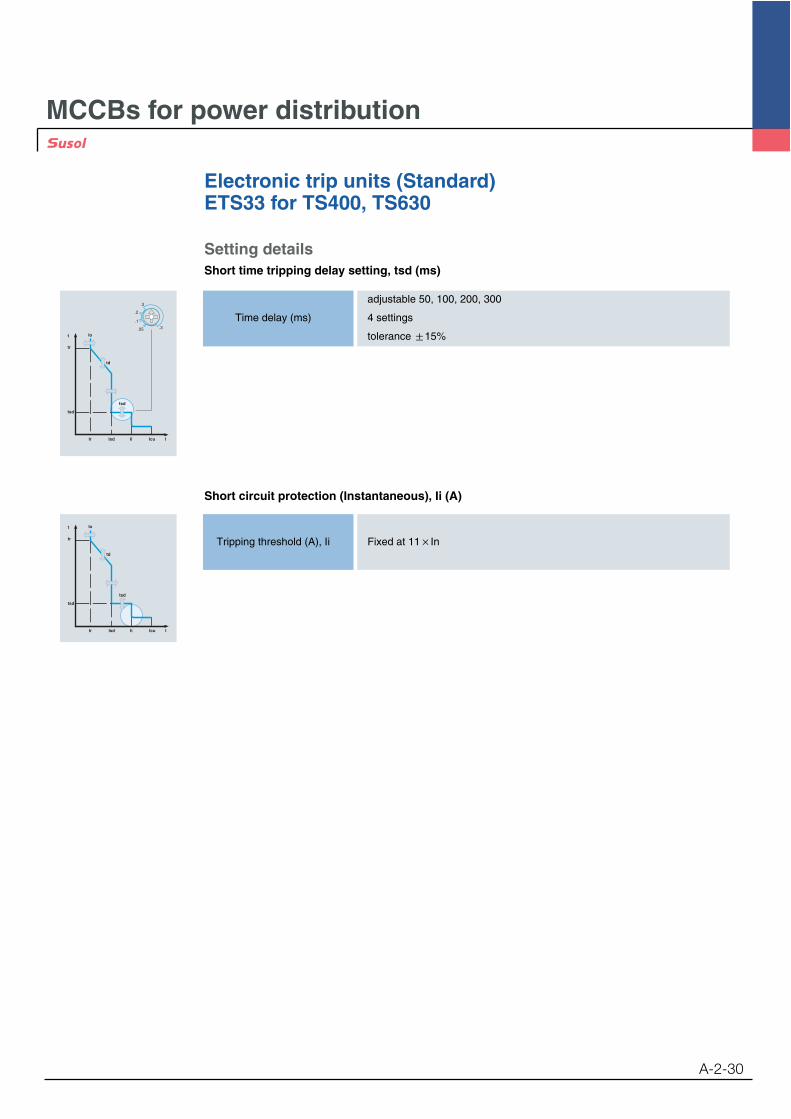
A-2-30
Setting detailsShort time tripping delay setting, tsd (ms)
adjustable 50, 100, 200, 300
Time delay (ms) 4 settings
tolerance 15%t
tr
tsd
Ir
Io
td
tsd
Isd Ii Icu I
.3
.3
.2
.1
.05
Short circuit protection (Instantaneous), Ii (A)
Tripping threshold (A), Ii Fixed at 11 In
t
tr
tsd
Ir
Io
td
tsd
Isd Ii Icu I
MCCBs for power distribution
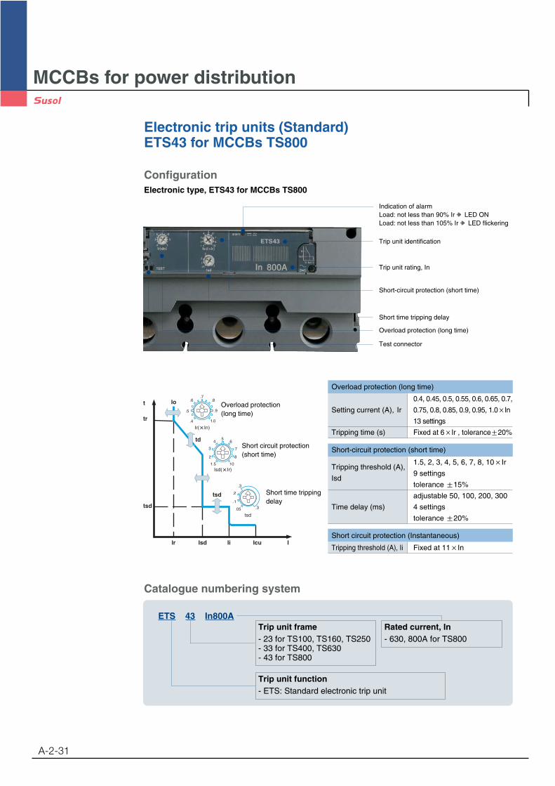
Electronic trip units (Standard)ETS43 for MCCBs TS800
A-2-31
Trip unit frame- 23 for TS100, TS160, TS250- 33 for TS400, TS630- 43 for TS800
Rated current, In- 630, 800A for TS800
Trip unit function- ETS: Standard electronic trip unit
ETS 43 In800A
Catalogue numbering system
ConfigurationElectronic type, ETS43 for MCCBs TS800
Trip unit identification
Indication of alarmLoad: not less than 90% Ir LED ONLoad: not less than 105% Ir LED flickering
Trip unit rating, In
Test connector
Short time tripping delay
Overload protection (long time)
Short-circuit protection (short time)
t
tr
tsd
Ir
Io
td
tsd
Isd Ii Icu I
.6
.5
.4
.7.8
.9
1.0
.3
.3
.2
.1
.05
tsd
4
3
2
56
7
8
1.5 10
Overload protection(long time)
Short circuit protection(short time)
Short time trippingdelay
Overload protection (long time)
Short circuit protection (Instantaneous)
Tripping threshold (A), Ii Fixed at 11 In
0.4, 0.45, 0.5, 0.55, 0.6, 0.65, 0.7,
Setting current (A), Ir 0.75, 0.8, 0.85, 0.9, 0.95, 1.0 In
13 settings
Tripping time (s) Fixed at 6 Ir , tolerance 20%
Tripping threshold (A),1.5, 2, 3, 4, 5, 6, 7, 8, 10 Ir
Isd9 settings
tolerance 15%
adjustable 50, 100, 200, 300
Time delay (ms) 4 settings
tolerance 20%
Short-circuit protection (short time)
MCCBs for power distribution
Electronic trip units (Standard)ETS43 for MCCBs TS800
A-2-32
t
tr
tsd
Ir
Io
td
tsd
Isd Ii Icu I
.6
.5
.4
.7.8
.9
1.0
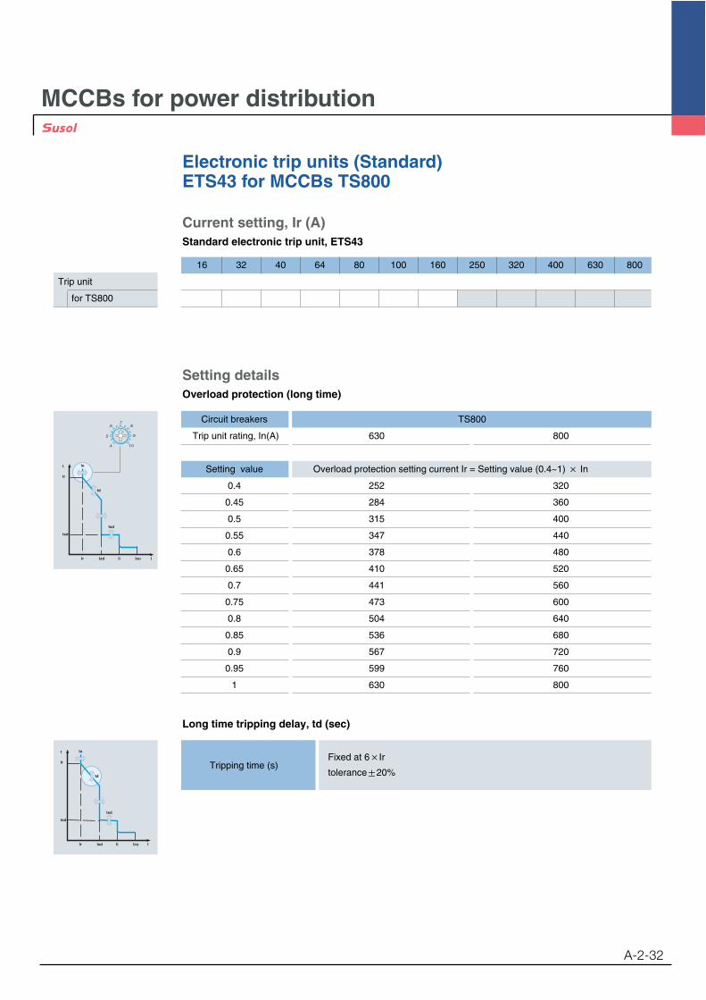
Setting detailsOverload protection (long time)
Circuit breakers TS800
Trip unit rating, In(A) 630 800
Setting value Overload protection setting current Ir = Setting value (0.4~1) In
0.4 252 320
0.45 284 360
0.5 315 400
0.55 347 440
0.6 378 480
0.65 410 520
0.7 441 560
0.75 473 600
0.8 504 640
0.85 536 680
0.9 567 720
0.95 599 760
1 630 800
Long time tripping delay, td (sec)
Tripping time (s)Fixed at 6 Ir
tolerance 20%
t
tr
tsd
Ir
Io
td
tsd
Isd Ii Icu I
Trip unit
for TS800
Current setting, Ir (A)Standard electronic trip unit, ETS43
16 32 40 64 80 100 160 250 320 400 630 800
MCCBs for power distribution
Electronic trip units (Standard)ETS43 for MCCBs TS800
A-2-33
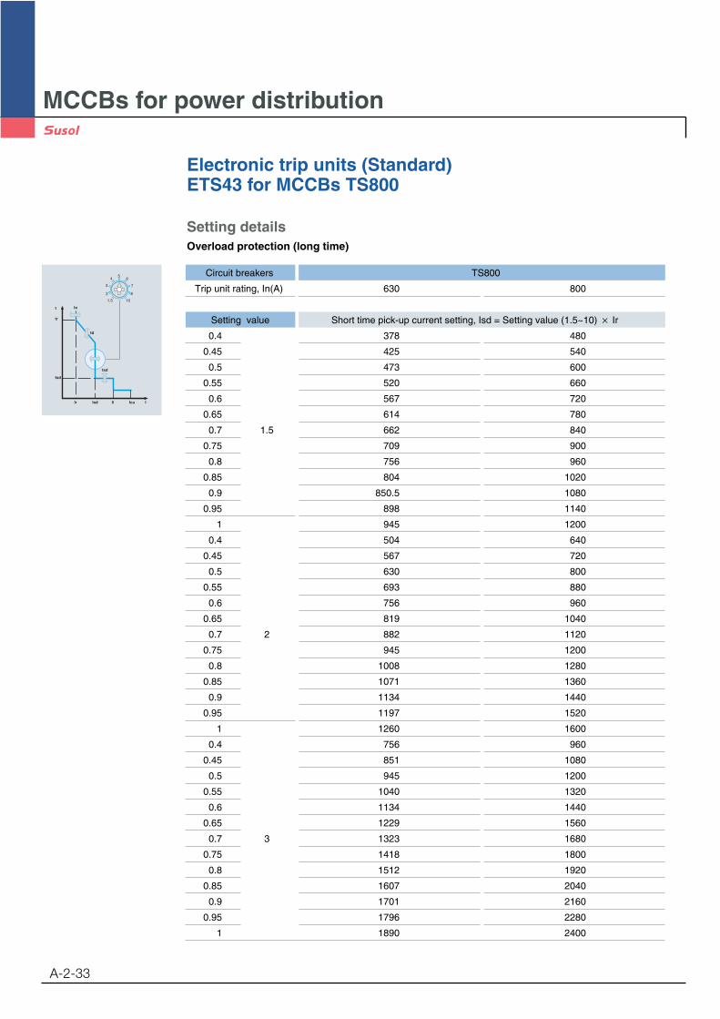
Setting detailsOverload protection (long time)
t
tr
tsd
Ir
Io
td
tsd
Isd Ii Icu I
4
3
2
56
7
8
1.5 10
Circuit breakers TS800
Trip unit rating, In(A) 630 800
Setting value Short time pick-up current setting, Isd = Setting value (1.5~10) Ir
0.4 378 480
0.45 425 540
0.5 473 600
0.55 520 660
0.6 567 720
0.65 614 780
0.7 1.5 662 840
0.75 709 900
0.8 756 960
0.85 804 1020
0.9 850.5 1080
0.95 898 1140
1 945 1200
0.4 504 640
0.45 567 720
0.5 630 800
0.55 693 880
0.6 756 960
0.65 819 1040
0.7 2 882 1120
0.75 945 1200
0.8 1008 1280
0.85 1071 1360
0.9 1134 1440
0.95 1197 1520
1 1260 1600
0.4 756 960
0.45 851 1080
0.5 945 1200
0.55 1040 1320
0.6 1134 1440
0.65 1229 1560
0.7 3 1323 1680
0.75 1418 1800
0.8 1512 1920
0.85 1607 2040
0.9 1701 2160
0.95 1796 2280
1 1890 2400
MCCBs for power distribution
Electronic trip units (Standard)ETS43 for MCCBs TS800
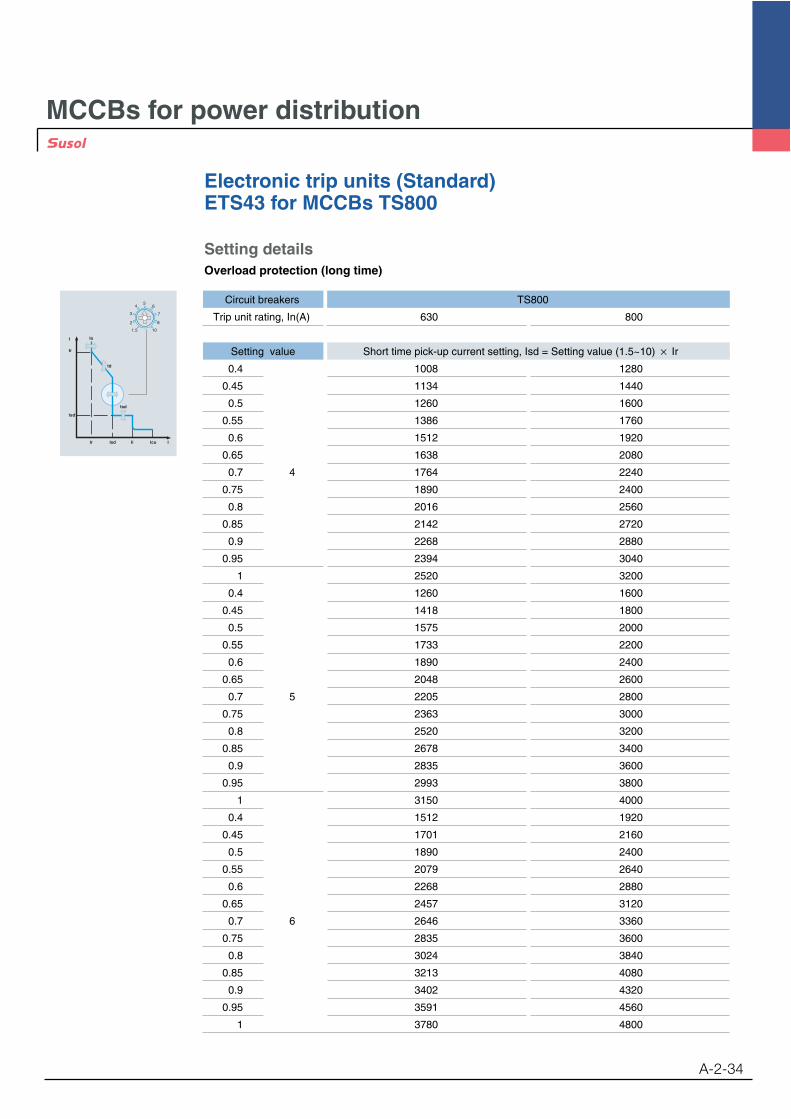
Setting detailsOverload protection (long time)
t
tr
tsd
Ir
Io
td
tsd
Isd Ii Icu I
4
3
2
56
7
8
1.5 10
Circuit breakers TS800
Trip unit rating, In(A) 630 800
Setting value Short time pick-up current setting, Isd = Setting value (1.5~10) Ir
0.4 1008 1280
0.45 1134 1440
0.5 1260 1600
0.55 1386 1760
0.6 1512 1920
0.65 1638 2080
0.7 4 1764 2240
0.75 1890 2400
0.8 2016 2560
0.85 2142 2720
0.9 2268 2880
0.95 2394 3040
1 2520 3200
0.4 1260 1600
0.45 1418 1800
0.5 1575 2000
0.55 1733 2200
0.6 1890 2400
0.65 2048 2600
0.7 5 2205 2800
0.75 2363 3000
0.8 2520 3200
0.85 2678 3400
0.9 2835 3600
0.95 2993 3800
1 3150 4000
0.4 1512 1920
0.45 1701 2160
0.5 1890 2400
0.55 2079 2640
0.6 2268 2880
0.65 2457 3120
0.7 6 2646 3360
0.75 2835 3600
0.8 3024 3840
0.85 3213 4080
0.9 3402 4320
0.95 3591 4560
1 3780 4800
A-2-34

MCCBs for power distribution
Electronic trip units (Standard)ETS43 for MCCBs TS800
A-2-35
Setting detailsShort-circuit protection (short time)
t
tr
tsd
Ir
Io
td
tsd
Isd Ii Icu I
4
3
2
56
7
8
1.5 10
Circuit breakers TS800
Trip unit rating, In(A) 630 800
Setting value Short time pick-up current setting, Isd = Setting value (1.5~10) Ir
0.4 1764 2240
0.45 1985 2520
0.5 2205 2800
0.55 2426 3080
0.6 2646 3360
0.65 2867 3640
0.7 7 3087 3920
0.75 3308 4200
0.8 3528 4480
0.85 3749 4760
0.9 3969 5040
0.95 4190 5320
1 4410 5600
0.4 2016 2560
0.45 2268 2880
0.5 2520 3200
0.55 2772 3520
0.6 3024 3840
0.65 3276 4160
0.7 8 3528 4480
0.75 3780 4800
0.8 4032 5120
0.85 4284 5440
0.9 4536 5760
0.95 4788 6080
1 5040 6400
0.4 2520 3200
0.45 2835 3600
0.5 3150 4000
0.55 3465 4400
0.6 3780 4800
0.65 4095 5200
0.7 10 4410 5600
0.75 4725 6000
0.8 5040 6400
0.85 5355 6800
0.9 5670 7200
0.95 5985 7600
1 6300 8000

MCCBs for power distribution
Electronic trip units (Standard)ETS43 for MCCBs TS800
A-2-36
Setting detailsShort time tripping delay setting, tsd (ms)
adjustable 50, 100, 200, 300
Time delay (ms) 4 settings
tolerance 15%t
tr
tsd
Ir
Io
td
tsd
Isd Ii Icu I
.3
.3
.2
.1
.05
Short circuit protection (Instantaneous), Ii (A)
Tripping threshold (A), Ii Fixed at 11 In
t
tr
tsd
Ir
Io
td
tsd
Isd Ii Icu I
MCCBs for power distribution
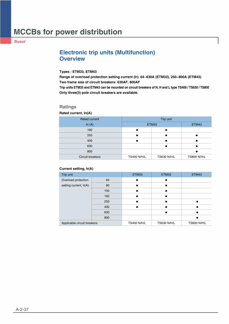
Electronic trip units (Multifunction)Overview
A-2-37
Types : ETM33, ETM43
Range of overload protection setting current (Ir): 64~630A (ETM33), 250~800A (ETM43)
Two frame size of circuit breakers: 630AF, 800AF
Trip units ETM33 and ETM43 can be mounted on circuit breakers of N, H and L type TS400 / TS630 / TS800
Only three(3) pole circuit breakers are available.
RatingsRated current, In(A)
Current setting, Ir(A)
Rated current Trip unit
In (A) ETM33 ETM43
160
250
400
630
800
Circuit breakers TS400 N/H/L TS630 N/H/L TS800 N/H/L
Trip unit ETM33 ETM33 ETM43
Overload protection 64
setting current, Ir(A) 80
100
160
250
400
630
800
Applicable circuit breakers TS400 N/H/L TS630 N/H/L TS800 N/H/L
MCCBs for power distribution
Electronic trip units (Multifunction)Overview
A-2-38
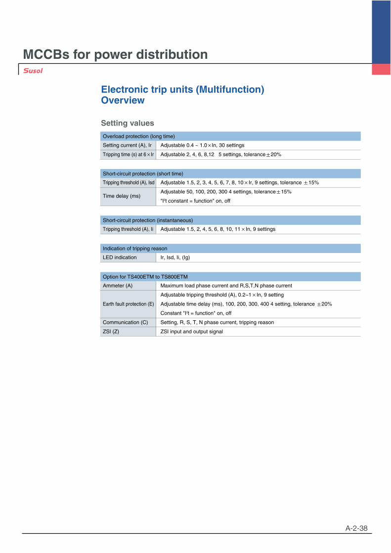
Setting values
Setting current (A), Ir Adjustable 0.4 ~ 1.0 In, 30 settings
Tripping time (s) at 6 Ir Adjustable 2, 4, 6, 8,12 5 settings, tolerance 20%
Tripping threshold (A), Isd Adjustable 1.5, 2, 3, 4, 5, 6, 7, 8, 10 Ir, 9 settings, tolerance 15%
Time delay (ms)Adjustable 50, 100, 200, 300 4 settings, tolerance 15%
"I2t constant = function" on, off
Ammeter (A) Maximum load phase current and R,S,T,N phase current
Adjustable tripping threshold (A), 0.2~1 In, 9 setting
Earth fault protection (E) Adjustable time delay (ms), 100, 200, 300, 400 4 setting, tolerance 20%
Constant "I2t = function" on, off
Communication (C) Setting, R, S, T, N phase current, tripping reason
ZSI (Z) ZSI input and output signal
Tripping threshold (A), Ii Adjustable 1.5, 2, 4, 5, 6, 8, 10, 11 In, 9 settings
LED indication Ir, Isd, Ii, (Ig)
Overload protection (long time)
Short-circuit protection (short time)
Short-circuit protection (instantaneous)
Indication of tripping reason
Option for TS400ETM to TS800ETM
MCCBs for power distribution
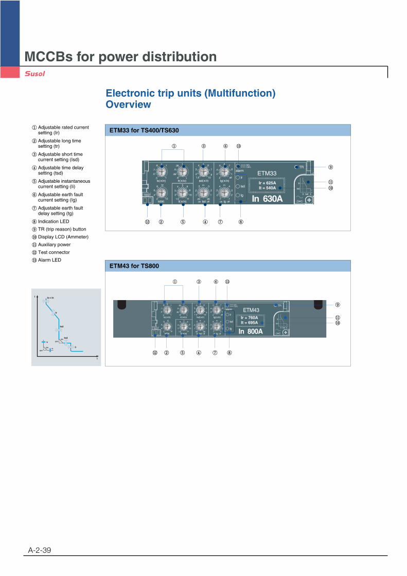
Electronic trip units (Multifunction)Overview
A-2-39
ETM33 for TS400/TS630Adjustable rated currentsetting (Ir)
Adjustable long timesetting (tr)
Adjustable short timecurrent setting (Isd)
Adjustable time delaysetting (tsd)
Adjustable instantaneouscurrent setting (Ii)
Adjustable earth faultcurrent setting (Ig)
Adjustable earth faultdelay setting (tg)
Indication LED
TR (trip reason) button
Display LCD (Ammeter)
Auxiliary power
Test connector
Alarm LED
tr
tsd
li
Isd
t
I
OFF
ON
lg
ta
OFFON
Ir = 625AIt = 540A
ETM43 for TS800
Ir = 760AIt = 695A

MCCBs for power distribution
Electronic trip units (Multifunction)ETM33 for TS400, TS630
A-2-40
Alarm indicationThe LED lights and remains lit when the load exceeds 90 % of Ir.The LED blinks for an overload( 105% Ir), warning that the circuit breaker may trip.
Fault indicationsLEDs indicate the type of fault that caused tripping:
Ir : overloadIsd : short-circuit ( short time, instantaneous)Ig : earth fault
If push the TR button to indicate the tripping reasion, the indication LED of tripping is ON.The information is however stored in memory and the LED can be reilluminated by pressing the TR button.The LED automatically goes off and the memory is cleared when the circuit breaker is reset.In normal condition, if push TR button, all indication LED is ON for testing auxiliary power and LED.
alarm
Ir
Isd
Ig
90%105%
Adjustable rated current setting (Ir)
Adjustable long time setting (tr)
Adjustable short time current setting (Isd)
Adjustable time delay setting (tsd)
Adjustable instantaneous current setting (Ii)
Adjustable earth fault current setting (Ig)
Adjustable earth fault delay setting (tg)
Indication LED
TR (trip reason) button
Display LCD (Ammeter)
Auxiliary power
Test connector
Alarm LED 90% Ir : ON,
105% Ir or more: ON-OFF
Configuration
Ir = 625AIt = 540A
MCCBs for power distribution
Electronic trip units (Multifunction)ETM33 for TS400, TS630
A-2-41
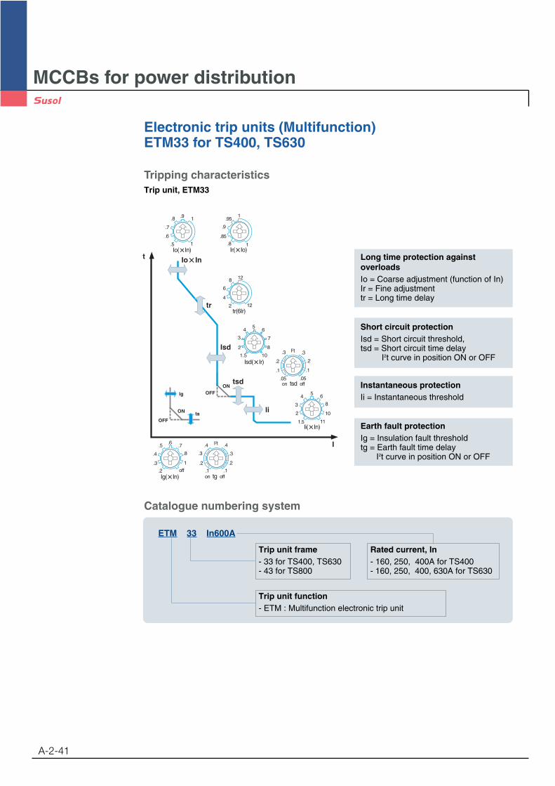
Tripping characteristicsTrip unit, ETM33
Trip unit frame- 33 for TS400, TS630- 43 for TS800
Rated current, In- 160, 250, 400A for TS400- 160, 250, 400, 630A for TS630
Trip unit function- ETM : Multifunction electronic trip unit
ETM 33 In600A
Catalogue numbering system
tr
tsd
li
Isd
t
I
1
1
.9.8
.7
.6
.5
tr(6Ir)12
12
2
8
6
4
1
1
.95
.85
.8
.9
111.5
2
3
4 5 6
8
10
1
.8
.7
.4
.6.5
.3
.2 offon tg off.1 .1
.2 .2
.3 .3
.4 .4I2t
on tsd off
.1.1
.2 .2
.3 .3I2t
.05 .05
OFF
ON
lg
ta
OFFON
4
3
2
56
7
8
1.5 10
Long time protection againstoverloadsIo = Coarse adjustment (function of In)Ir = Fine adjustmenttr = Long time delay
Short circuit protectionIsd = Short circuit threshold,tsd = Short circuit time delay
I2t curve in position ON or OFF
Instantaneous protectionIi = Instantaneous threshold
Earth fault protectionIg = Insulation fault thresholdtg = Earth fault time delay
I2t curve in position ON or OFF
MCCBs for power distribution
Electronic trip units (Multifunction)ETM33 for TS400, TS630
A-2-42
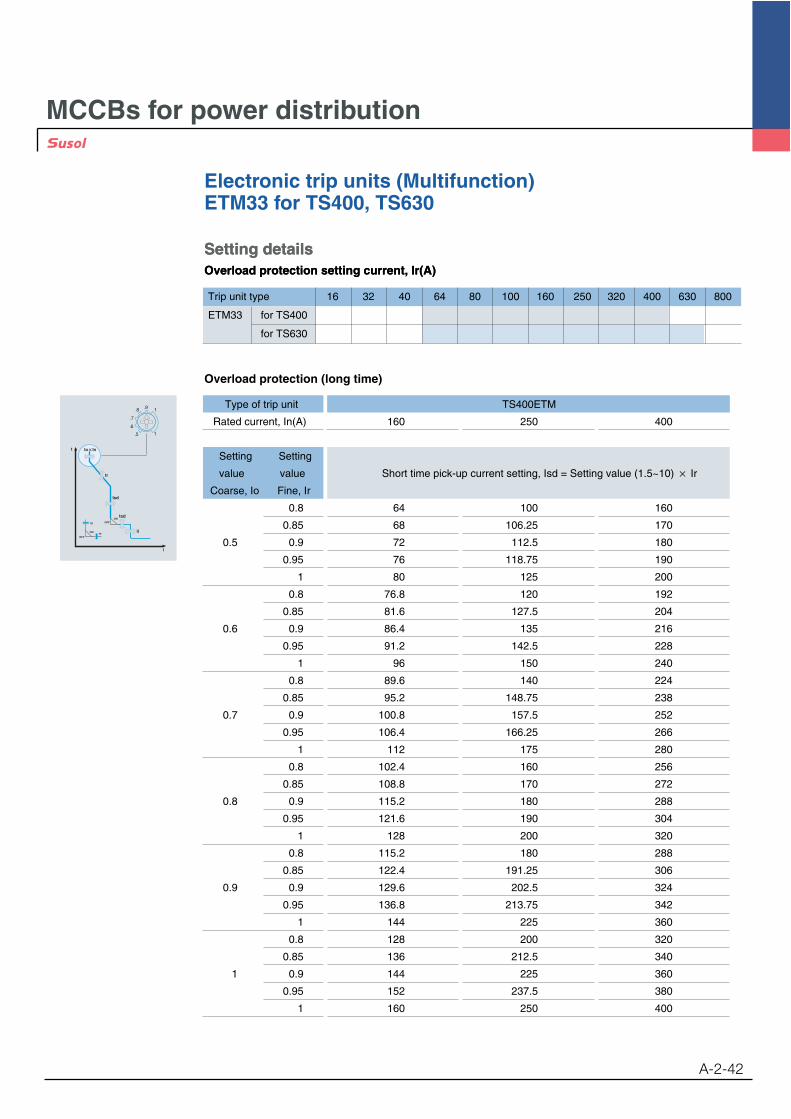
Setting detailsOverload protection setting current, Ir(A)
Setting detailsOverload protection setting current, Ir(A)
Trip unit type 16 32 40 64 80 100 160 250 320 400 630 800
ETM33 for TS400
for TS630
Overload protection (long time)
tr
tsd
li
Isd
t
I
OFF
ON
lg
ta
OFFON
1
1
.9.8
.7
.6
.5
Type of trip unit TS400ETM
Rated current, In(A) 160 250 400
Setting Setting
value value Short time pick-up current setting, Isd = Setting value (1.5~10) Ir
Coarse, Io Fine, Ir
0.8 64 100 160
0.85 68 106.25 170
0.5 0.9 72 112.5 180
0.95 76 118.75 190
1 80 125 200
0.8 76.8 120 192
0.85 81.6 127.5 204
0.6 0.9 86.4 135 216
0.95 91.2 142.5 228
1 96 150 240
0.8 89.6 140 224
0.85 95.2 148.75 238
0.7 0.9 100.8 157.5 252
0.95 106.4 166.25 266
1 112 175 280
0.8 102.4 160 256
0.85 108.8 170 272
0.8 0.9 115.2 180 288
0.95 121.6 190 304
1 128 200 320
0.8 115.2 180 288
0.85 122.4 191.25 306
0.9 0.9 129.6 202.5 324
0.95 136.8 213.75 342
1 144 225 360
0.8 128 200 320
0.85 136 212.5 340
1 0.9 144 225 360
0.95 152 237.5 380
1 160 250 400
MCCBs for power distribution
Electronic trip units (Multifunction)ETM33 for TS400, TS630
A-2-43
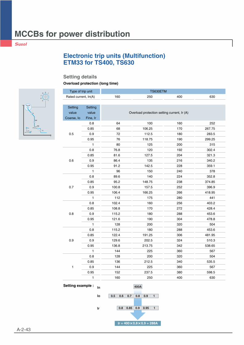
Setting detailsOverload protection (long time)
Setting example : In
Io
Ir
400A
0.5 0.6 0.7 0.8 0.9 1
0.8 0.85 0.9 0.95 1
tr
tsd
li
Isd
t
I
OFF
ON
lg
ta
OFFON
1
1
.9.8
.7
.6
.5
Type of trip unit TS630ETM
Rated current, In(A) 160 250 400 630
Setting Setting
value value Overload protection setting current, Ir (A)
Coarse, Io Fine, Ir
0.8 64 100 160 252
0.85 68 106.25 170 267.75
0.5 0.9 72 112.5 180 283.5
0.95 76 118.75 190 299.25
1 80 125 200 315
0.8 76.8 120 192 302.4
0.85 81.6 127.5 204 321.3
0.6 0.9 86.4 135 216 340.2
0.95 91.2 142.5 228 359.1
1 96 150 240 378
0.8 89.6 140 224 352.8
0.85 95.2 148.75 238 374.85
0.7 0.9 100.8 157.5 252 396.9
0.95 106.4 166.25 266 418.95
1 112 175 280 441
0.8 102.4 160 256 403.2
0.85 108.8 170 272 428.4
0.8 0.9 115.2 180 288 453.6
0.95 121.6 190 304 478.8
1 128 200 320 504
0.8 115.2 180 288 453.6
0.85 122.4 191.25 306 481.95
0.9 0.9 129.6 202.5 324 510.3
0.95 136.8 213.75 342 538.65
1 144 225 360 567
0.8 128 200 320 504
0.85 136 212.5 340 535.5
1 0.9 144 225 360 567
0.95 152 237.5 380 598.5
1 160 250 400 630

MCCBs for power distribution
Electronic trip units (Multifunction)ETM33 for TS400, TS630
A-2-44
Short circuit protectionThe short circuit threshold, Isd is a multiple of the overload setting, Ir.
Setting example :
Short circuit time delay
0.1....0.4s
0.2....1Inlg
tg
0.1....0.4s
0.2....1In
tg
lg 1
.8
.7
.4
.6.5
.3
.2 off
on tg off.1 .1
.2 .2
.3 .3
.4 .4I2t
0.05...0.3stsd 0.05...0.3s
tsd
Earth fault protection(E), optionalThe ETM trip units measure the vectorial sum of the three phase current and, if present, that of theneutral conductor. If the sum of these values exceeds the set current thresholds for a period of time greater than thetime delay, the breaker is tripped.
The breaker trips when thecurrent exceeds 1440A.
400A
0.5 0.6 0.7 0.8 0.9 1
0.8 0.85 0.9 0.95 1
1.5 2 3 4 5 6 7 8 10
4
3
2
56
7
8
1.5 10
on tsd off
.1.1
.2 .2
.3 .3I2t
.05 .05
Ig = insulation fault thresholdtg = earth fault time delay
MCCBs for power distribution
Electronic trip units (Multifunction)ETM33 for TS400, TS630
A-2-45
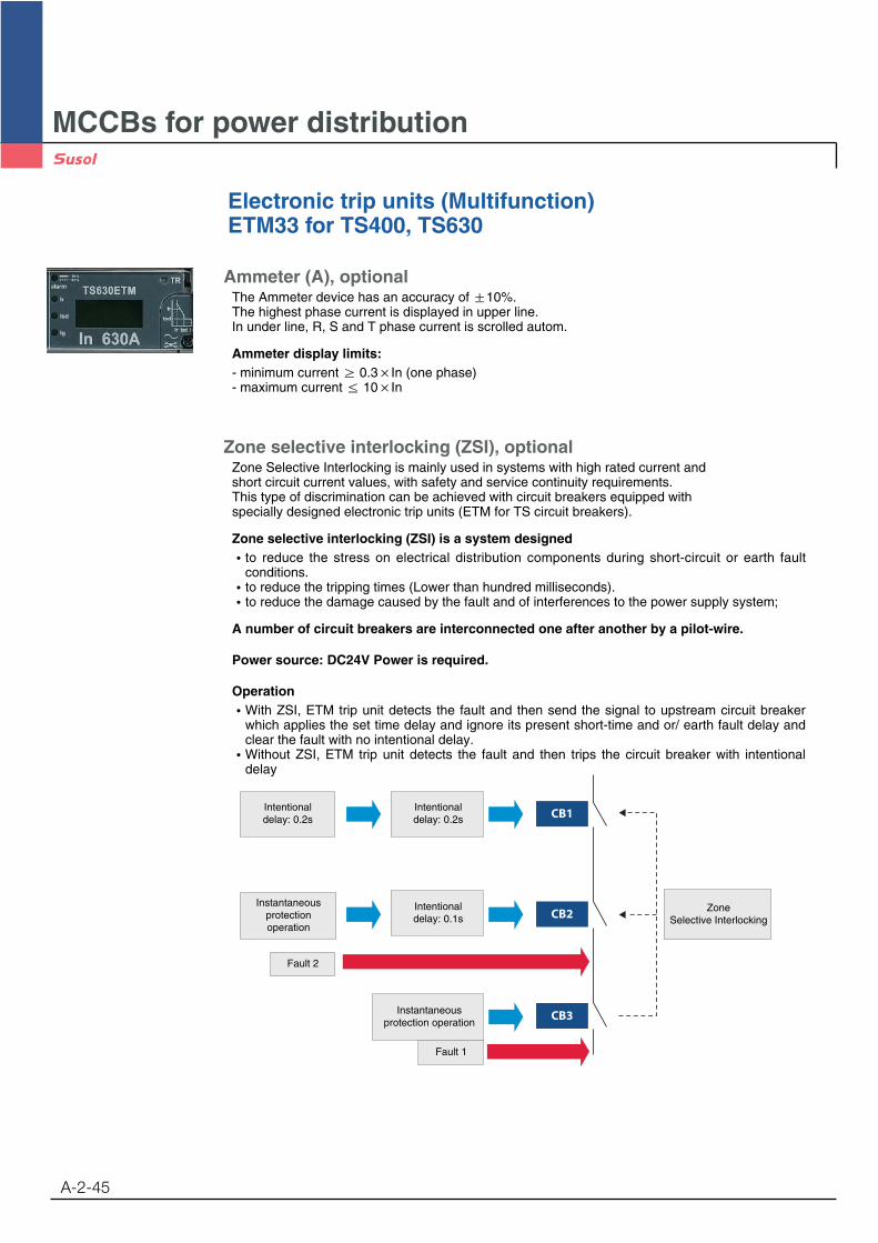
Ammeter (A), optionalThe Ammeter device has an accuracy of 10%.The highest phase current is displayed in upper line. In under line, R, S and T phase current is scrolled autom.
Ammeter display limits:- minimum current 0.3 In (one phase)- maximum current 10 In
Zone selective interlocking (ZSI), optionalZone Selective Interlocking is mainly used in systems with high rated current and short circuit current values, with safety and service continuity requirements. This type of discrimination can be achieved with circuit breakers equipped with specially designed electronic trip units (ETM for TS circuit breakers).
Zone selective interlocking (ZSI) is a system designedto reduce the stress on electrical distribution components during short-circuit or earth faultconditions.to reduce the tripping times (Lower than hundred milliseconds).to reduce the damage caused by the fault and of interferences to the power supply system;
A number of circuit breakers are interconnected one after another by a pilot-wire.
Power source: DC24V Power is required.
OperationWith ZSI, ETM trip unit detects the fault and then send the signal to upstream circuit breakerwhich applies the set time delay and ignore its present short-time and or/ earth fault delay andclear the fault with no intentional delay.Without ZSI, ETM trip unit detects the fault and then trips the circuit breaker with intentionaldelay
CB1
CB2
CB3
Intentionaldelay: 0.2s
Intentionaldelay: 0.2s
Instantaneousprotectionoperation
Instantaneousprotection operation
Fault 2
Fault 1
Intentionaldelay: 0.1s
ZoneSelective Interlocking
MCCBs for power distribution
Electronic trip units (Multifunction)ETM33 for TS400, TS630
A-2-46
Communication(C), optionalCommunication interface: RS485 (Modbus-RTU)The Modbus RS485 system is an open bus on which communicating Modbus devices areinstalled. All kinds of PLCs and computers can be connected to the bus.
Transmitted data :Protection setting valuesHighest current of the three phasesMeasurement: R, S, T and N phase currentFault reading: Type of fault (Overload, short-circuit, etc)
The setting of communication address using TR button and LCD display (Ammeter).
Power source: DC24V Power is required.
Combination of optionsA(Ammeter) Z(Zone selective interlocking)E(Earth fault protection) Z+AA+E Z+EA +C(Communication) Z+A+EA+E+C Z+A +C
Z+A+E+C

MCCBs for power distribution
Electronic trip units (Multifunction)ETM33 for TS400, TS630
A-2-47
Display current value (RMS) of phase which is carrying maximum ineach phaseDisplay current value (RMS) of each phase at an interval of every 2seconds.
Press “TR” button for 5 seconds.
The cursor in the first row is flickering at an interval of every 0.5 seconds.
Whenever pressing “TR” button, the number will change from 1 to247.
Press “TR” button for 4 seconds.
The cursor in the second row is flickering at an interval of every 0.5 seconds.
Whenever pressing “TR” button, the following figures will bedisplayed in order. [3P160 / 3P250 / 3P400 / 3P630 / 3P800 /4P160 / 4P250 / 4P400 / 4P630 / 4P800 ]
The value set by manufacturer according to customer’s orderspecification.
For saving setting value, press “TR” button for 5 seconds.
Then, the LCD return to Ammeter function.
Note: If there is no action on ”TR” button over 8 seconds, the LCD return to first stage.
I r - 1 2 6 0 A
I s - 1 2 6 5 A
A d d r : 6 0 1
C T : 3 P 1 6 0
A d d r : 6 0 1
C T : 3 P 1 6 0
I r - 1 2 6 0 A
I s - 1 2 6 5 A
Menu structure of the electronic trip unit (ETM)

MCCBs for power distribution
Electronic trip units (Multifunction)ETM33 for TS400, TS630
A-2-48
Feature of trip unit according to option
ETM33
In 630A
ETM33
ETM33
ETM33
In 630A
In 630A
In 630A
ETM33 A+E
ETM33 A+E+C
ETM33 Z+A+E
ETM33 Z+A+E+C
ETM33 A
ETM33 A+C
ETM33 Z+A
ETM33 Z+A+C
ETM33 E
ETM33 Z+E
ETM33
ETM33 Z
MCCBs for power distribution
Electronic trip units (Multifunction)ETM43 for TS800
A-2-49
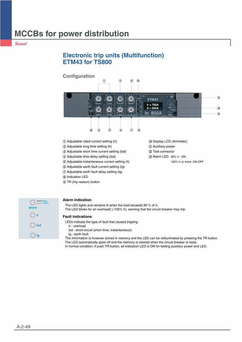
Alarm indicationThe LED lights and remains lit when the load exceeds 90 % of Ir.The LED blinks for an overload( 105% Ir), warning that the circuit breaker may trip.
Fault indicationsLEDs indicate the type of fault that caused tripping:
Ir : overloadIsd : short-circuit (short time, instantaneous)Ig : earth fault
The information is however stored in memory and the LED can be reilluminated by pressing the TR button.The LED automatically goes off and the memory is cleared when the circuit breaker is reset.In normal condition, if push TR button, all indication LED is ON for testing auxiliary power and LED.
alarm
Ir
Isd
Ig
90%105%
Adjustable rated current setting (Ir)
Adjustable long time setting (tr)
Adjustable short time current setting (Isd)
Adjustable time delay setting (tsd)
Adjustable instantaneous current setting (Ii)
Adjustable earth fault current setting (Ig)
Adjustable earth fault delay setting (tg)
Indication LED
TR (trip reason) button
Display LCD (Ammeter)
Auxiliary power
Test connector
Alarm LED 90% Ir : ON,
105% Ir or more: ON-OFF
Configuration
Ir = 760AIt = 695A
MCCBs for power distribution
Electronic trip units (Multifunction)ETM43 for TS800
A-2-50
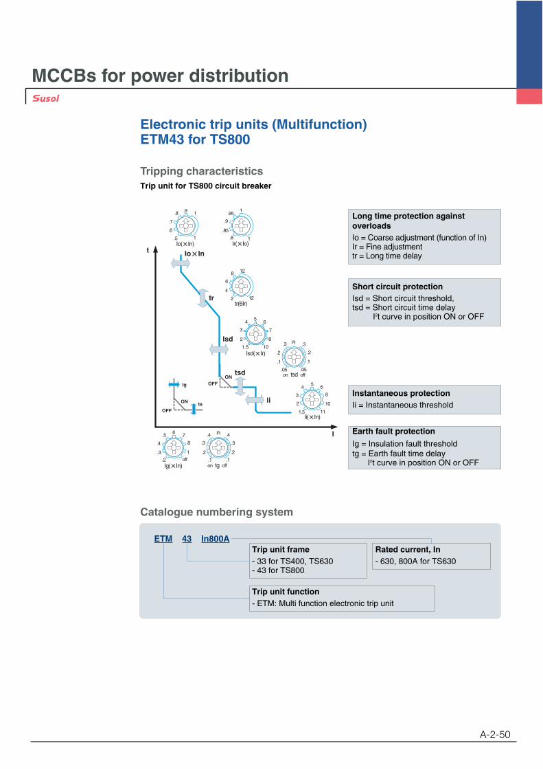
Tripping characteristicsTrip unit for TS800 circuit breaker
tr
tsd
li
Isd
t
I
1
1
.9.8
.7
.6
.5
tr(6Ir)12
12
2
8
6
4
1
1
.95
.85
.8
.9
111.5
2
3
4 5 6
8
10
1
.8
.7
.4
.6.5
.3
.2 offon tg off.1 .1
.2 .2
.3 .3
.4 .4I2t
on tsd off
.1.1
.2 .2
.3 .3I2t
.05 .05
OFF
ON
lg
ta
OFFON
4
3
2
56
7
8
1.5 10
Long time protection againstoverloadsIo = Coarse adjustment (function of In)Ir = Fine adjustmenttr = Long time delay
Short circuit protectionIsd = Short circuit threshold,tsd = Short circuit time delay
I2t curve in position ON or OFF
Instantaneous protectionIi = Instantaneous threshold
Earth fault protection
Ig = Insulation fault thresholdtg = Earth fault time delay
I2t curve in position ON or OFF
Trip unit frame- 33 for TS400, TS630- 43 for TS800
Rated current, In- 630, 800A for TS630
Trip unit function- ETM: Multi function electronic trip unit
ETM 43 In800A
Catalogue numbering system
MCCBs for power distribution
Electronic trip units (Multifunction)ETM43 for TS800
A-2-51
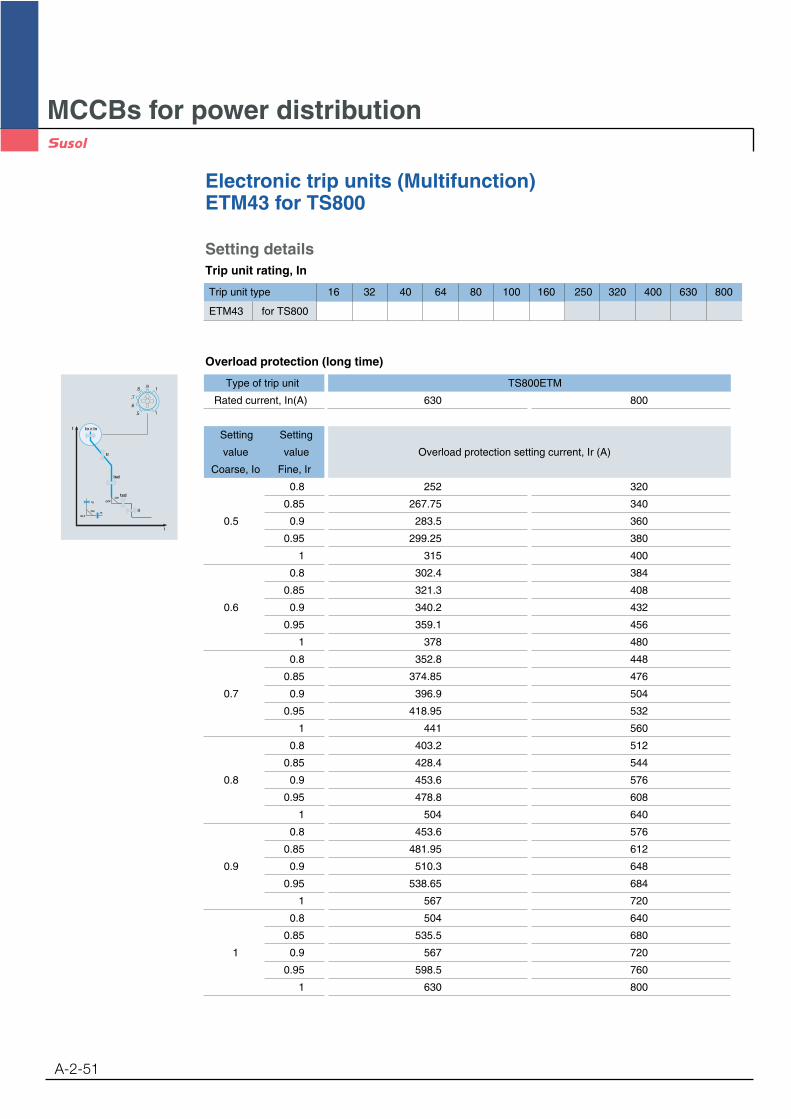
Setting detailsTrip unit rating, In
Trip unit type 16 32 40 64 80 100 160 250 320 400 630 800
ETM43 for TS800
Overload protection (long time)
tr
tsd
li
Isd
t
I
OFF
ON
lg
ta
OFFON
1
1
.9.8
.7
.6
.5
Type of trip unit TS800ETM
Rated current, In(A) 630 800
Setting Setting
value value Overload protection setting current, Ir (A)
Coarse, Io Fine, Ir
0.8 252 320
0.85 267.75 340
0.5 0.9 283.5 360
0.95 299.25 380
1 315 400
0.8 302.4 384
0.85 321.3 408
0.6 0.9 340.2 432
0.95 359.1 456
1 378 480
0.8 352.8 448
0.85 374.85 476
0.7 0.9 396.9 504
0.95 418.95 532
1 441 560
0.8 403.2 512
0.85 428.4 544
0.8 0.9 453.6 576
0.95 478.8 608
1 504 640
0.8 453.6 576
0.85 481.95 612
0.9 0.9 510.3 648
0.95 538.65 684
1 567 720
0.8 504 640
0.85 535.5 680
1 0.9 567 720
0.95 598.5 760
1 630 800
MCCBs for power distribution
Electronic trip units (Multifunction)ETM43 for TS800
A-2-52
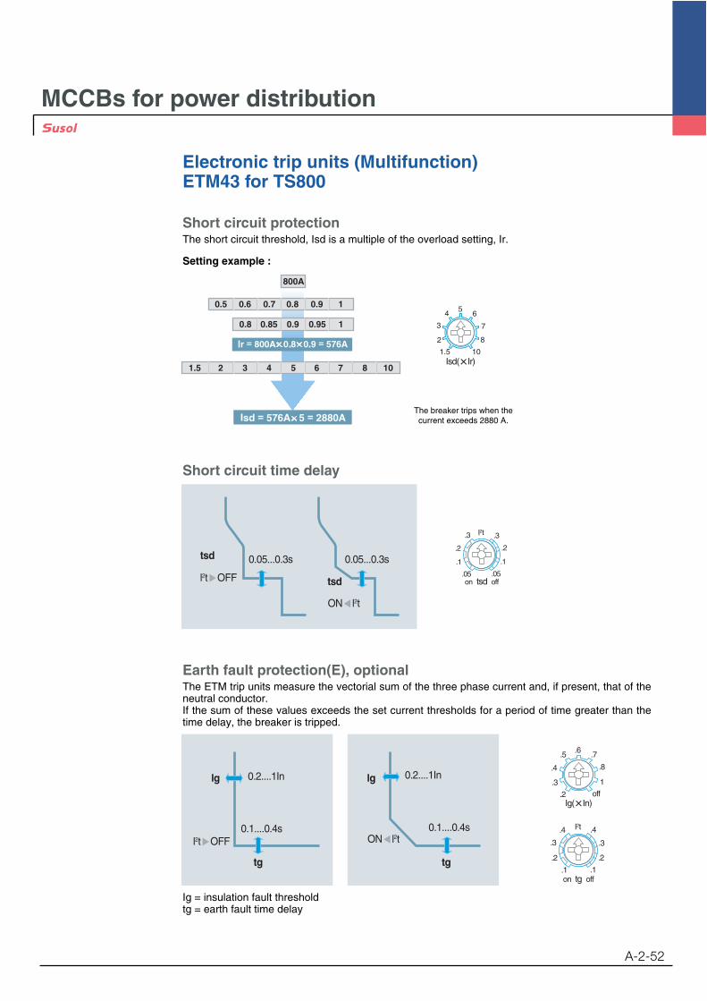
Short circuit protectionThe short circuit threshold, Isd is a multiple of the overload setting, Ir.
Setting example :
Short circuit time delay
0.1....0.4s
0.2....1Inlg
tg
0.1....0.4s
0.2....1In
tg
lg 1
.8
.7
.4
.6.5
.3
.2 off
on tg off.1 .1
.2 .2
.3 .3
.4 .4I2t
0.05...0.3stsd 0.05...0.3s
tsd
Earth fault protection(E), optionalThe ETM trip units measure the vectorial sum of the three phase current and, if present, that of theneutral conductor. If the sum of these values exceeds the set current thresholds for a period of time greater than thetime delay, the breaker is tripped.
The breaker trips when thecurrent exceeds 2880 A.
800A
0.5 0.6 0.7 0.8 0.9 1
0.8 0.85 0.9 0.95 1
1.5 2 3 4 5 6 7 8 10
4
3
2
56
7
8
1.5 10
on tsd off
.1.1
.2 .2
.3 .3I2t
.05 .05
Ig = insulation fault thresholdtg = earth fault time delay

MCCBs for power distribution
Electronic trip units (Multifunction)ETM43 for TS800
A-2-53
Ammeter (A), optionalThe Ammeter device has an accuracy of 10%.The highest phase current is displayed in upper line. In under line, R, S and T phase current is scrolled autom.
Ammeter display limits:- minimum current 0.3 In (one phase)- maximum current 10 In
Zone selective interlocking (ZSI), optionalZone Selective Interlocking is mainly used in systems with high rated current and short circuit current values, with safety and service continuity requirements. This type of discrimination can be achieved with circuit breakers equipped with specially designed electronic trip units (ETM for TS circuit breakers).
Zone selective interlocking (ZSI) is a system designedto reduce the stress on electrical distribution components during short-circuit or earth faultconditions.to reduce the tripping times (Lower than hundred milliseconds).to reduce the damage caused by the fault and of interferences to the power supply system;
A number of circuit breakers are interconnected one after another by a pilot-wire.
Power source: DC24V Power is required.
OperationWith ZSI, ETM trip unit detects the fault and then send the signal to upstream circuit breakerwhich applies the set time delay and ignore its present short-time and or/ earth fault delay andclear the fault with no intentional delay.Without ZSI, ETM trip unit detects the fault and then trips the circuit breaker with intentionaldelay
CB1
CB2
CB3
Intentionaldelay: 0.2s
Intentionaldelay: 0.2s
Instantaneousprotectionoperation
Instantaneousprotection operation
Fault 2
Fault 1
Intentionaldelay: 0.1s
ZoneSelective Interlocking

MCCBs for power distribution
Electronic trip units (Multifunction)ETM43 for TS800
A-2-54
Communication(C), optionalCommunication interface: RS485 (Modbus-RTU)The Modbus RS485 system is an open bus on which communicating Modbus devices areinstalled. All kinds of PLCs and computers can be connected to the bus.
Transmitted data:Protection setting valuesHighest current of the three phasesMeasurement: R, S, T and N phase currentFault reading: Type of fault (Overload, short-circuit, etc)
The setting of communication address using TR button and LCD display (Ammeter).
Power source: DC24V Power is required.
Combination of optionsA(Ammeter) Z(Zone selective interlocking)E(Earth fault protection) Z+AA+E Z+EA +C(Communication) Z+A+EA+E+C Z+A +C
Z+A+E+C

MCCBs for power distribution
Electronic trip units (Multifunction)ETM43 for TS800
A-2-55
Display current value (RMS) of phase which is carrying maximum ineach phaseDisplay current value (RMS) of each phase at an interval of every 2seconds.
Press “TR” button for 5 seconds.
The cursor in the first row is flickering at an interval of every 0.5 seconds.
Whenever pressing “TR” button, the number will change from 1 to247.
Press “TR” button for 4 seconds.
The cursor in the second row is flickering at an interval of every 0.5 seconds.
Whenever pressing “TR” button, the following figures will bedisplayed in order. [3P160 / 3P250 / 3P400 / 3P630 / 3P800 /4P160 / 4P250 / 4P400 / 4P630 / 4P800 ]
The value set by manufacturer according to customer’s orderspecification.
For saving setting value, press “TR” button for 5 seconds.
Then, the LCD return to Ammeter function.
Note: If there is no action on ”TR” button over 8 seconds, the LCD return to first stage.
I r - 1 2 6 0 A
I s - 1 2 6 5 A
A d d r : 6 0 1
C T : 3 P 1 6 0
A d d r : 6 0 1
C T : 3 P 1 6 0
I r - 1 2 6 0 A
I s - 1 2 6 5 A
Menu structure of the electronic trip unit (ETM)

MCCBs for power distribution
Electronic trip units (Multifunction)ETM43 for TS800
A-2-56
Feature of trip unit according to option
ETM43
In 800A
ETM43
ETM43
ETM43
In 800A
In 800A
In 800A
ETM43 A+E
ETM43 A+E+C
ETM43 Z+A+E
ETM43 Z+A+E+C
ETM43 A
ETM43 A+C
ETM43 Z+A
ETM43 Z+A+C
ETM43 E
ETM43 Z+E
ETM43
ETM43 Z
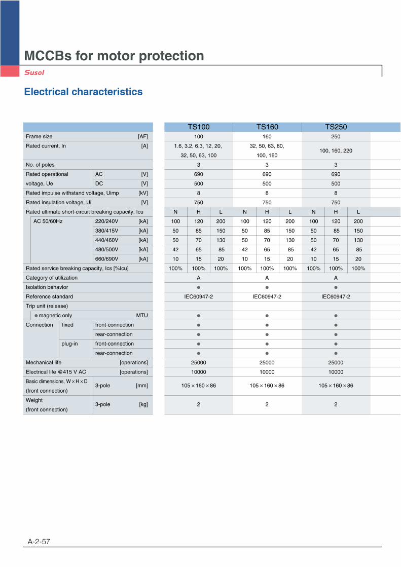
MCCBs for motor protection
Electrical characteristics
A-2-57
100 160 250
1.6, 3.2, 6.3, 12, 20, 32, 50, 63, 80,100, 160, 220
32, 50, 63, 100 100, 160
3 3 3
690 690 690
500 500 500
8 8 8
750 750 750
N H L N H L N H L
100 120 200 100 120 200 100 120 200
50 85 150 50 85 150 50 85 150
50 70 130 50 70 130 50 70 130
42 65 85 42 65 85 42 65 85
10 15 20 10 15 20 10 15 20
100% 100% 100% 100% 100% 100% 100% 100% 100%
A A A
IEC60947-2 IEC60947-2 IEC60947-2
25000 25000 25000
10000 10000 10000
105 160 86 105 160 86 105 160 86
2 2 2
TS100 TS160 TS250Frame size [AF]
Rated current, In [A]
No. of poles
Rated operational AC [V]
voltage, Ue DC [V]
Rated impulse withstand voltage, Uimp [kV]
Rated insulation voltage, Ui [V]
Rated ultimate short-circuit breaking capacity, Icu
AC 50/60Hz 220/240V [kA]
380/415V [kA]
440/460V [kA]
480/500V [kA]
660/690V [kA]
Rated service breaking capacity, Ics [%Icu]
Category of utilization
Isolation behavior
Reference standard
Trip unit (release)
magnetic only MTU
Connection fixed front-connection
rear-connection
plug-in front-connection
rear-connection
Mechanical life [operations]
Electrical life @415 V AC [operations]
Basic dimensions, W H D3-pole [mm]
(front connection)
Weight3-pole [kg]
(front connection)
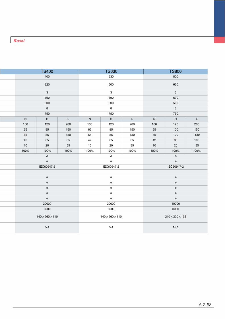
A-2-58
TS400 TS630 TS800400 630 800
320 500 630
3 3 3
690 690 690
500 500 500
8 8 8
750 750 750
N H L N H L N H L
100 120 200 100 120 200 100 120 200
65 85 150 65 85 150 65 100 150
65 85 130 65 85 130 65 100 130
42 65 85 42 65 85 42 85 100
10 20 35 10 20 35 10 20 35
100% 100% 100% 100% 100% 100% 100% 100% 100%
A A A
IEC60947-2 IEC60947-2 IEC60947-2
20000 20000 10000
6000 6000 3000
140 260 110 140 260 110 210 320 135
5.4 5.4 15.1
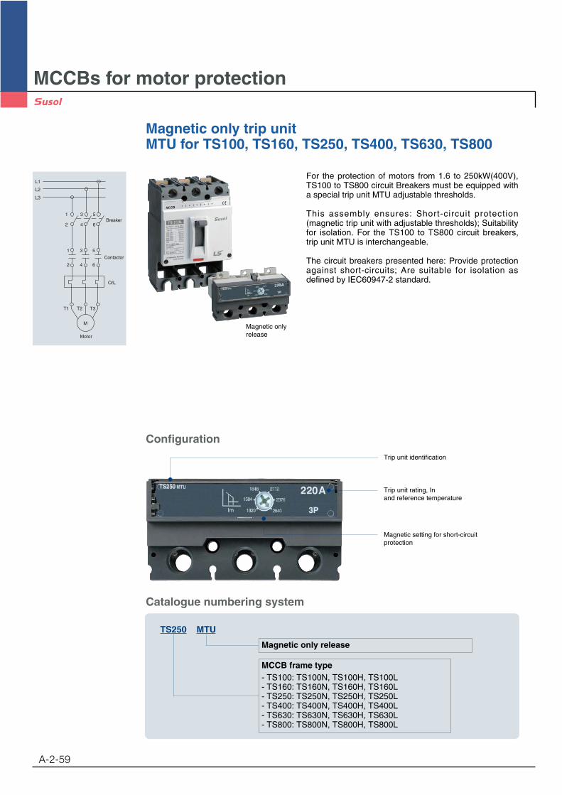
MCCBs for motor protection
Magnetic only trip unitMTU for TS100, TS160, TS250, TS400, TS630, TS800
A-2-59
Magnetic only release
MCCB frame type- TS100: TS100N, TS100H, TS100L- TS160: TS160N, TS160H, TS160L- TS250: TS250N, TS250H, TS250L- TS400: TS400N, TS400H, TS400L- TS630: TS630N, TS630H, TS630L- TS800: TS800N, TS800H, TS800L
TS250 MTU
Catalogue numbering system
Configuration
Trip unit rating, Inand reference temperature
Trip unit identification
Magnetic setting for short-circuitprotection
For the protection of motors from 1.6 to 250kW(400V),TS100 to TS800 circuit Breakers must be equipped witha special trip unit MTU adjustable thresholds.
This assembly ensures: Short-circuit protection(magnetic trip unit with adjustable thresholds); Suitabilityfor isolation. For the TS100 to TS800 circuit breakers,trip unit MTU is interchangeable.
The circuit breakers presented here: Provide protectionagainst short-circuits; Are suitable for isolation asdefined by IEC60947-2 standard.
Magnetic onlyrelease
M
Motor
T1
2 4 6
2 4 6
1 3 5
1
L1
L2
L3
3 5
T2 T3
O/L
Contactor
Breaker
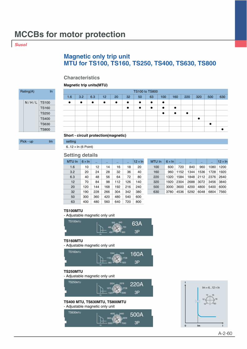
MCCBs for motor protection
A-2-60
Magnetic only trip unitMTU for TS100, TS160, TS250, TS400, TS630, TS800
Im = 6...12 In
t
Im0 I
14 16
18
20
12
10
Pick - up Im setting
6..12 In (6 Point)
Short - circuit protection(magnetic)
TS250MTU 220A3P
2024 2376
2728
3080
1672
1320Im
TS250MTU- Adjustable magnetic only unit
TS160MTU 160A3P
1344 1536
1728
1920
1152
960Im
TS160MTU- Adjustable magnetic only unit
TS100MTU 63A3P
560 640
720
800
480
400Im
TS100MTU- Adjustable magnetic only unit
TS630MTU 500A4600 5400
6200
7000
3800
3000Im
TS400 MTU, TS630MTU, TS800MTU- Adjustable magnetic only unit
TS100 to TS800
1.6 3.2 6.3 12 20 32 50 63 100 160 220 320 500 630
CharacteristicsMagnetic trip units(MTU)
Setting detailsMTU In 6 In .. .. .. .. 12 In
1.6 10 12 14 16 18 20
3.2 20 24 28 32 36 40
6.3 40 48 56 64 72 80
12 70 84 98 112 126 140
20 120 144 168 192 216 240
32 190 228 266 304 342 380
50 300 360 420 480 540 600
63 400 480 560 640 720 800
MTU In 6 In .. .. .. .. 12 In
100 600 720 840 960 1080 1200
160 960 1152 1344 1536 1728 1920
220 1320 1584 1848 2112 2376 2640
320 1920 2304 2688 3072 3456 3840
500 3000 3600 4200 4800 5400 6000
630 3780 4536 5292 6048 6804 7560
Rating(A) In
N / H / L TS100
TS160
TS250
TS400
TS630
TS800
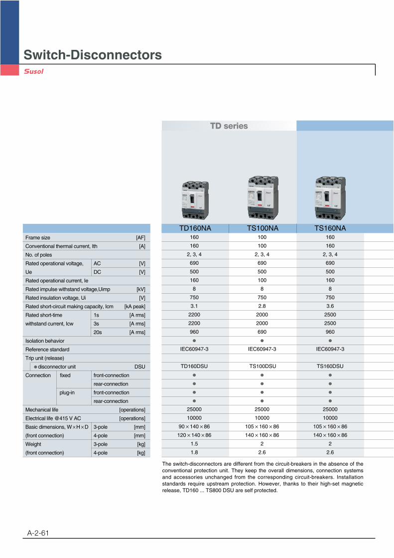
Switch-Disconnectors
A-2-61
TD series
160 100 160
160 100 160
2, 3, 4 2, 3, 4 2, 3, 4
690 690 690
500 500 500
160 100 160
8 8 8
750 750 750
3.1 2.8 3.6
2200 2000 2500
2200 2000 2500
960 690 960
IEC60947-3 IEC60947-3 IEC60947-3
TD160DSU TS100DSU TS160DSU
25000 25000 25000
10000 10000 10000
90 140 86 105 160 86 105 160 86
120 140 86 140 160 86 140 160 86
1.5 2 2
1.8 2.6 2.6
Frame size [AF]
Conventional thermal current, Ith [A]
No. of poles
Rated operational voltage, AC [V]
Ue DC [V]
Rated operational current, Ie
Rated impulse withstand voltage,Uimp [kV]
Rated insulation voltage, Ui [V]
Rated short-circuit making capacity, Icm [kA peak]
Rated short-time 1s [A rms]
withstand current, Icw 3s [A rms]
20s [A rms]
Isolation behavior
Reference standard
Trip unit (release)
disconnector unit DSU
Connection fixed front-connection
rear-connection
plug-in front-connection
rear-connection
Mechanical life [operations]
Electrical life @415 V AC [operations]
Basic dimensions, W H D 3-pole [mm]
(front connection) 4-pole [mm]
Weight 3-pole [kg]
(front connection) 4-pole [kg]
The switch-disconnectors are different from the circuit-breakers in the absence of theconventional protection unit. They keep the overall dimensions, connection systemsand accessories unchanged from the corresponding circuit-breakers. Installationstandards require upstream protection. However, thanks to their high-set magneticrelease, TD160 ... TS800 DSU are self protected.
TD160NA TS100NA TS160NA
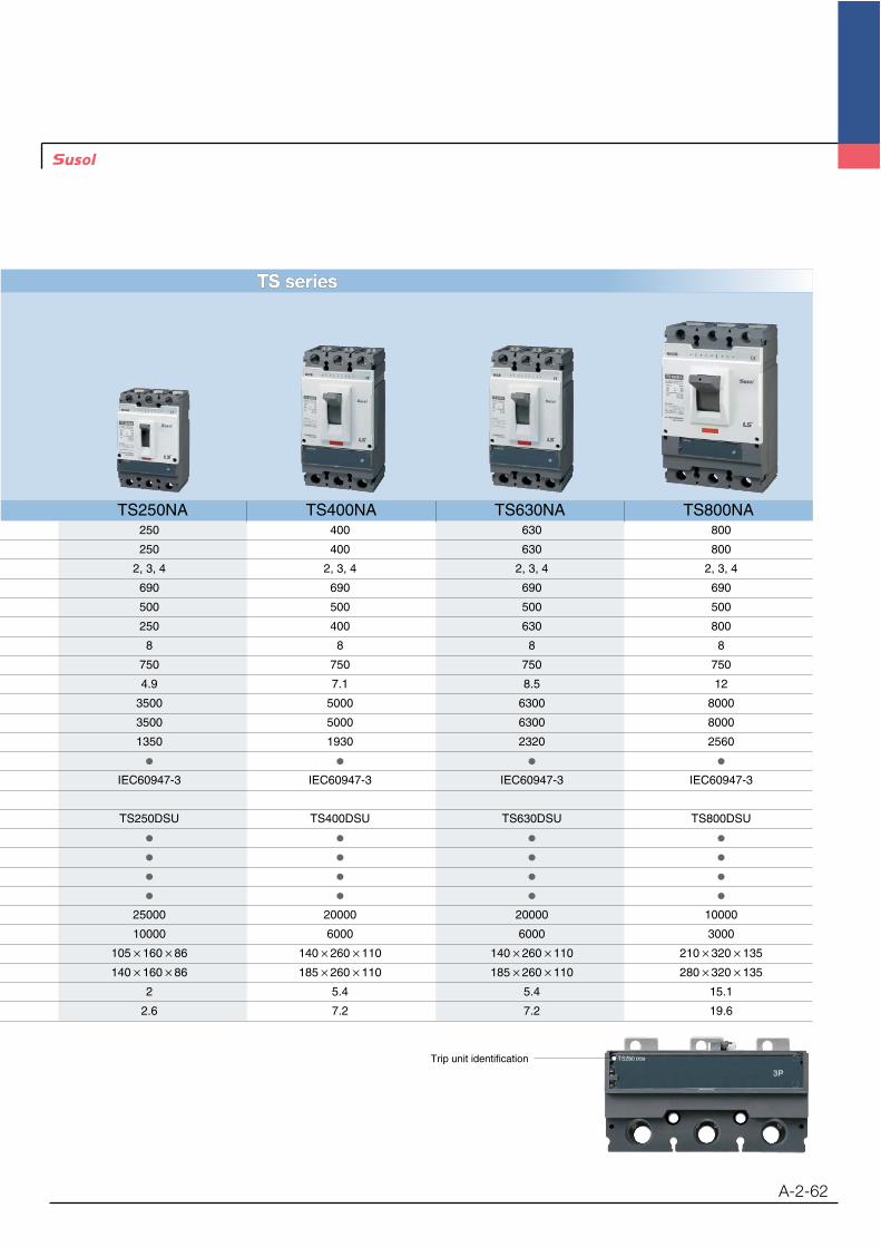
A-2-62
TS seriesTS series
250 400 630 800
250 400 630 800
2, 3, 4 2, 3, 4 2, 3, 4 2, 3, 4
690 690 690 690
500 500 500 500
250 400 630 800
8 8 8 8
750 750 750 750
4.9 7.1 8.5 12
3500 5000 6300 8000
3500 5000 6300 8000
1350 1930 2320 2560
IEC60947-3 IEC60947-3 IEC60947-3 IEC60947-3
TS250DSU TS400DSU TS630DSU TS800DSU
25000 20000 20000 10000
10000 6000 6000 3000
105 160 86 140 260 110 140 260 110 210 320 135
140 160 86 185 260 110 185 260 110 280 320 135
2 5.4 5.4 15.1
2.6 7.2 7.2 19.6
Trip unit identification
TS800NATS250NA TS400NA TS630NA


