Download - Lunokhod-1 Soviet Lunar Surface Vehicle

ARPA ORDER NO.: 189-1
R-802-ARPA
September 1971
Lunokhod-1 Soviet Lunar Surface Vehicle
Simon Kassel
A Report prepared for
ADVANCED RESEARCH PROJECTS AGENCY
Rand SANTA MONICA, CA. 90406
APPROVED FOR PUBLIC RELEASE; DISTRIBUTION UNUMJTED

This research is supported by the Advanced Research Projects Agency under Contract No. DAHC15 67 C 0141. Views or conclusions contained in this study should not be interpreted as representing the official opinion or policy of Rand or of ARPA •

ARPA ORDER NO.: 189-1
R-802-ARPA
September 1971
Lunokhod-1 Soviet Lunar Surface Vehicle
Simon Kassel
A Report p~epared for
ADVANCED RESEARCH PROJECTS AGENCY
Rand SANTA MONICA. CA 90406
APPROVED FOR PUBLIC RELEASE; DISTRIBUTION UNLIMITED

Published by The Rand Corporation

-iii-
PREFACE
This report has been prepared within the scope of the Soviet liter
ature exploitation program to provide a somewhat more complete descrip
tion of the nature and capabilities of the Soviet moon rover than that
generally available in any one of the published sources. For this rea
son the entire series of newspaper accounts published since the moon
landing has been scanned to obtain a more-or-less consistent picture.
Because of the large input of data and to save time, the usual procedure
of referencing each publication has been omitted.
Rand's Soviet Literature Exploitation program is supported by the
Advanced Research Projects Agency.


-v-
SUMMARY
The following account of the Soviet lunar-exploration vehicle,
Lunokhod-1, delivered to the lunar surface in the Sea of Rains on November
17, 1970 by the Luna-17 mission, has been assembled from a very large vol
ume of literature published in the USSR between that date and May 1971.
This descriptive treatment has been prepared to aid in the evaluation of
Lunokhod-1 as a new tool of unmanned extraterrestrial exploration, as a
scientific instrument, and above all, as a specimen of special-purpose So
viet cybernetics and equipment.
The mere fact that the vehicle has so far traveled nearly 10 km over
rugged terrain and apparently continues to do so indicates success of the
concept of a remote drone interacting directly with an unknown and hostile
environment. Its progress has been slow but steady; it comes alive during
lunar days and it is shut down for the nights, giving its operators a
considerable wealth of experience with the concept of dormancy. Another
novel area where experience is being accumulated steadily is man-machine
interaction with prolonged time delay. It is this concept that seems to
fascinate the Soviets the most and that has produced the most detailed
technical information.
As a scientific laboratory the vehicle represents a fairly modest
capability. Its sensory equipment comprises narrow-band television
systems, mechanical probes, a chemical analysis system, X-ray and cosmic
ray detectors, and assorted temperature and pressure gauges. However, the
telemetry associated with the transmission of their data to the earth must
be quite formidable. According to Soviet publications the data-flow on
the condition of the vehicle's wheels alone exceeds all the information
received from all the artificial satellites during the first three years
of the space era. The significant point to consider is that, however
limited are the experimental resources of the vehicle, they are being
applied systematically if slowly to an ever-widening area of the moon, an
area uncontaminated by rocket exhaust or any preparatory human activity.
The steady input of data is said to be already taxing the computer resources
of the USSR.
-vi-
The principal purpose of any automation equipment aboard Lunokhod-1
is to ensure the safety and viability of the vehicle and its systems. In
this role the degree of necessary sophistication of the equipment is
directly related to the normal operating speeds of the vehicle, since the
extent of autonomous control required rises sharply with speed. No
detailed specifications of any computers aboard Lunokhod-1 have been
found in the literature except for brief and general descriptions of some
of their functions. On the other hand, it is highly probable that the
normal operating speed of Lunokhod-1 is in the vicinity of 1 km/hr. At
such a speed, considering the size and geometry of the vehicle, the tele
vision link, and the continuous roll-and-pitch telemetry, the need for
autonomous maneuvering systems is not very great. The automatic systems
for this purpose that were reported in the literature comprise cutoff de
vices to stop the vehicle when certain operating parameters are exceeded,
and automation employing logic and memory components to execute programmed
standard maneuvers such as time-limited straight-line runs and 20-deg
turns. An adequate amount of sophistication is also required to ensure the
reliability of command reception involving signal-from-noise filtering.
Certain experimental procedures, such as soil testing, also appear to in
volve extensive automatic operation.
-vii-
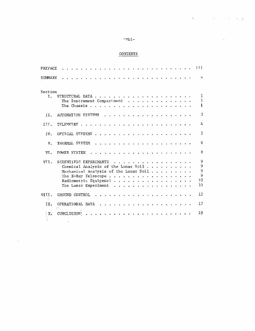
CONTENTS
PREFACE
SUMMARY
Section I. STRUCTURAL DATA . . . . . . .
The Instrument Compartment The Chassis . . .
II. AUTOMATION SYSTEMS
III. TELEMETRY ...
IV. OPTICAL SYSTEMS
V. THEID1AL SYSTE1"I
VI. POWER SYSTEM
VII. SCIENTIFIC EXPERIMENTS Chemical Analysis of the Lunar Soil Mechanical Analysis of the Lunar Soil • The X-Ray Telescope . Radiometric Equipment The Laser Experiment
VIII. GROUND CONTROL
IX. OPERATIONAL DATA
\X. CONCLUSION\
iii
v
1 1 1
3
4
5
6
8
9 9 9 9
10 10
12
17
19


-1-
I. STRUCTURAL DATA
The automatic lunar-exploration vehicle Lunokhod-1 weighs 756 kg,
is 2.2 m long and about 2.2 m wide. The vehicle consists of two main
parts: the instrument compartment and the chassis.
THE INSTRUMENT COMPARTMENT
The airtight instrument compartment has the form of a truncated cone.
It is made of magnesium alloy, assuring sufficient strength and lightness.
The upper portion of the compartment is used as a cooling radiator and is
covered by a special lid which has a twofold purpose. At night the lid
covers the radiator and prevents the emission of heat from the instrument
compartment. During lunar day the lid is open, exposing elements of the
solar battery on its inner side to the sun.
The compartment contains radio telemetry transmitters and receivers,
vehicle remote-control system, power-supply system, automatic switching
systems, thermal regulation systems, and electronic converters for the ex
perimental equipment.
Outside the forward portion of the instrument compartment there are
portholes for television cameras, electric drive for a steerable high
gain antenna for the transmission of television images, a wide-angle an
tenna for the reception of radio commands and transmission of telemetry,
scientific instruments, and the laser reflector. On each side of the
compartment there are two panoramic telephotometer cameras, and four
whip antennas to receive radio commands from the earth.
THE CHASSIS
The instrument compartment is mounted on an eight-wheel self-propelled
chassis, which has been designed to provide extended reliability and high
mobility. The geometry of the undercarriage, the specific pressure on the
surface, the tractive characteristics of the chassis, the parameters of
the elastic suspension, and the design of the wheels' bearing surfaces
all contribute to the vehicle's ability to move about on a loose, friable
surface, to ascend steep grades, and to traverse craters and ridges

-2-
commensurable with the size of the wheelbase. The chassis comprises
4 sets of 510-mm wheel pairs, automation equipment, override safety
system, a sensor system for determining the physical properties of the
soil and for evaluating the cross-country performance of the vehicle,
an isotopic heat source for the thermal system, and a trailing wheel
(the ninth wheel) with its retraction mechanism. Each of the eight
wheels is provided with an individual power drive and independent tor
sional suspension; each hub contains an electric motor, a reduction gear,
a brake, a mechanism for disconnecting the power drive, wheel revolution
counters, and temperature gauges. Lunokhod is turned by varying the
appropriate wheels' speed and direction of rotation. Any wheel can also
be explosively jettisoned. Braking is accomplished by running the motors
in the electrodynamic braking mode or with electromagnetic disc brakes.
The vehicle can continue to move even if only two wheels on each side
are powered.
Distances traveled are measured by counting the number of revolutions
of the leading wheels. The free-rolling ninth wh.eel (raised and lowered
by a special drive) is used to measure slippage.

-3-
II. AUTOMATION SYSTEMS
The automation system is designed to ensure control of the vehicle movement activated by radio commands from the earth, measurement and monitoring of the main-chassis parameters, and automatic operation of the
mechanical soil-testing equipment.
The entire vehicle-movement control is accomplished by 5 "go" commands and 1 "stop" command. The commands are executed with the aid of logic and memory circuits that select a suitable movement mode, store information on the preceding mode, and activate control elements of the electric motors. The movement modes include "straight-line" motion for programmed time intervals and "turn" motion for programmed degrees of turn.
The safety override system stops the vehicle automatically when it reaches the limits of roll and pitch angles or of the wheel motor load~
If necessary, power can be disconnected from one or several wheels without impairing the necessary traction.
A set of sensors continuously measure roll and pitch of the vehicle, traction motor currents, and the RPM and temperature of the wheels.
The system includes computer elements operating in conjunction with telemetry to provide for reliable extraction of command signal from the high noise level and to handle a high rate of incoming data. The processing rate is of the order of several thousand commands.

-4-
III. TELENETRY
The telemetry system of Lunokhod-1 employs two frequency bands simul
taneously. The reception of each command from ground control is acknowl
edged, the command is executed, and its completion again signaled to ground
control.
Telemetry signals to ground control fall into several categories.
Signals transmitted during lunar day and night comprise information
on the temperature and pressure of the vehicle components. During lunar
night the systems are periodically interrogated.
Signals transmitted during the motion of the vehicle include data on
wheel temperature and RPM, currents to wheel motors, wheel-ground inter
action dynamics, television and telephotometer output, and roll-and-pitch
data. This information takes up a considerable portion of the telemetry
transmission.
Signals transmitted during vehicle stopover periods during duty cycles
include data of scientific experiments. Navigation of the vehicle requires
a large telemetric capability. The navigational system is based on a
specially developed method employing a course gyroscope, a gyro vertical
in conjunction with the telephotometers, images of the sun and earth
taken simultaneously, and the horizon images transmitted by the television
system of the vehicle.
-5-
IV. OPTICAL SYSTEMS
The vehicle carries two separate television systems, each serving a
specific purpose. The first is a narrow-band television system consisting
of two cameras mounted on the forward part of the instrument compartment.
It transmits images required by the crew to control the motion of the ve
hicle. The rate of image transmission of the system is lower than the
broadcasting television standard. It is considered sufficient in view of
the slow change of the landscape with the motion of the vehicle and amounts
to 1 frame per 3 to 20 sec, depending on the nature of the land profile
and the speed of the vehicle.
The second system provides a stereo-panoramic view of the lunar surface;
it also shows sectors of the sky for navigational purposes. The system
consists of 4 panoramic, mechanically scanning telephotometer cameras, identical in design, mounted in pairs on both sides of the vehicle. On each
side one camera operates through an angle of view of slightly over 180 deg
in the horizontal plane and 30 deg in the vertical plane. The other oper
ates within 360 deg in the vertical plane and 30 deg in the horizontal. One
camera of each pair has a built-in device to determine the local vertical.
The telemetry output of this system is transmitted to ground control where
it is processed by computer into a graphic display on paper tape. This
method is said to be particularly useful in application to the study of
craters. Stereo-panoramic views, displaying images of a given region at
various angles, have yielded data on surface details that could not have
been obtained by any other means.
The navigational use of the telephotometers is illustrated by the pro
cedure in which the vehicle is driven to a flat site and oriented in such a way that the telephotometers can pick up the earth and the sun simul
taneously. The resulting data are processed by ground computer to fix
the bearing of the vehicle. The accumulated error of this method over a
month's activity was a little more than 1 deg.

-6-
V. THERMAL SYSTEM
The vehicle has two thermal circuits: hot and cold. The cold circuit
includes a cooling radiator situated in the upper part of the instrument
compartment. The external surface of the radiator is almost ideally smooth
and covered by a special thermal radiating layer with an extremely small
absorption coefficient and a large capacity to radiate heat. The entire
body of the vehicle is covered with a thick thermal insulating jacket.
However, the jacket is insufficient to protect the interior from solar
heat. Therefore a continuously operating fan drives a gaseous mixture
through the cooling system. Excess heat is delivered to the cooling
radiator and radiated into space through the thermal layer. This occurs
even when the radiator is exposed to solar rays. Thus the material operates
only in one direction; it radiates but does not absorb. At night the
operation of the radiator ceases by closing the solar-battery cover. The
heat emitted by the radiator is then reflected back into the machine. The
hot system takes over, and special baffles automatically divert the gas
coolant into the heating system, where it is heated by an isotopic source.
The isotopic heat source is designed for several months' operation~
At sunrise and sunset the solar battery is exposed to the sun and the
hot system is used to compensate for the radiated heat at that time.
The hot and cold systems are switched automatically by thermal sensors.
The cold system is switched on when the temperature rises above 20°C. The
system was able to withstand 100°C, which occurred during the fourth lunar
noon, and many external parts were heated to more than 100°. However, inside
the airtight compartment the temperature was maintained within the pre
scribed limits.
The upper lid is also closed at the end of the lunar day to prevent
heat loss. The temperature-regulation system functions autonomously at
night.
The normal temperature range within the instrument compartment is from
+10 to +30°C. The pressure range is from 735 to 770 mm Hg. The tempera
ture range of external parts of the structure (such as the wheels or
antennas) is from -90 to +150°C.

-7-
In January the Lunokhod was tested towards the end of the lunar day
to determine its response to thermal conditions. How much heat it lost
with its cover open and with it closed was measured. As a result of
these tests, during the February eclipse Lunokhod was considered safe
enough to leave at night with the cover open and the heating system
turned on. After the reappearance of the sun, Lunokhod was capable of
normal operation, even though the solar battery lid has been as hot as
+140°C.
The material comprising the antennas and wheels can withstand 300°C
temperature changes.

-8-
VI. POWER SYSTEM
Solar and chemical batteries provide the electrical power. The
chief source of power is the solar battery whose cells, mounted on the
inside of the instrument compartment's lid, can be positioned at any
angle from 0 to 180 deg for the maximum utilization of solar energy.
To prepare the vehicle for the two weeks of the lunar night, it is
first turned to face the east so that the first rays of the rising sun
will fall on the solar battery.
During the lunar day the solar battery is continuously facing the
sun and charging the storage battery. This is continued until the storage
batteries are fully charged, whereupon the solar battery is disconnected.
The opening of the lid with the solar battery is one of the first operations
preceding the day's work and is carried out at sunrise.
The total electric power consumption of the vehicle in motion on the
lunar surface has been compared to that of an electric iron.
Present study of the vehicle indicates that it has considerable re
serves of power and can pull an identical vehicle behind without reducing
its speed.

-9-
VII. SCIENTIFIC EXPERIMENTS
CHEMICAL ANALYSIS OF THE LUNAR SOIL
The Rifm spectrometer consists of an isotopic source which irradiates
the investigated sector of the path and thus induces X-ray emission from
atoms of various elements constituting the lunar soil. The X-ray receiver
is a system of specially developed proportional counters with characteris
tic filters. The information on the energy spectrum and intensity of
X-rays is recorded by a 64-channel amplitude analyzer.
MECHANICAL ANALYSIS OF THE LUNAR SOIL
Of all the scientific experiments, the greatest amount of information
was obtained from measuring the bearing strength of lunar soil and the
mechanics of interaction between the soil and the vehicle's wheels. The
soil-testing program employs two types of devices. One is a penetrometer
which measures the strength of soil and operates only when the vehicle is
at rest. The other device measures the traction and operates only when
the vehicle is in motion by means of a ninth wheel, which rolls without
slipping. The penetrometer is a conical paddle driven into the soil and
rotated. A set of sensors continuously measures the force required to
rotate the paddle, its rotation angle, and depth of penetration. This
operation is performed regularly every 15 to 30 m of the path. The me
chanical properties of the soil are also studied from the image of the
wheel tracks transmitted by television. The bearing capacity of the soil
varied from 0.2 to 1.1 kg/cm2 ; resistance to shear varied from 0.02 to
0.09 kg/cm2 .
THE X-RAY TELESCOPE
The X-ray telescope consists of two proportional counters for X-ray
quanta designed for the energy region from 2,000 to 10,000 ev (wavelength
of l-6°A). The counters are installed behind collimators that limit the
field of vision of each counter to a cone with an angle of about 3.5 deg.
Both counters are directed at the local zenith when the vehicle is in a
horizontal position. One of the counters is covered by a filter opaque

-10-
to the investigated X-ray region. Thus, one of the counters records cosmic
X-ray radiation together with the cosmic-ray background while the second
counter records only the background. The X-ray observations are carried
out only while the vehicle is at a standstill. In 18 to 20 hours the tele
scope rotates through 9 to 10 deg.
During the vehicle's second lunar day, X-ray radiation was registered,
both in the plane of our galaxy and perpendicular to it. The intensity
of this radiation has been found to be steady in general, but certain sec
tors have been recorded--at least 4 of the 33 studied by the telescope-
where discrete (localized) X-ray sources are possible.
RADIOMETRIC EQUIPMENT
The equipment is designed to measure corpuscular flows of cosmic rays,
mainly in energy regions that are inaccessible to research on the earth's
surface.
THE LASER EXPERIMENT
The most widely publicized is the experiment with the corner reflec
tor carried by the vehicle for laser ranging.
The reflector is a panel of 14 four-sided prisms arrayed in a plane;
a laser signal is reflected three times in a prism and directed back to
its source on earth. The prisms are made of specially uniform glass having a
low thermal expansion coefficient and refractive index. A thermal shield
has been included which will minimize heat transfer to and from the prisms.
The reflector, developed and manufactured in France by the Sud
Aviation firm on order from the National Center of Space Research, possesses
high optical qualities and, in the opinion of specialists, will permit a
number of interesting scientific measurements to be conducted.
The Soviet transmitter is a Q-switched ruby laser developed by the
Lebedev Physics Institute for the 2.6-m telescope at the Crimean Astro
physical Observatory. A 10-sec pulse is reflected from the panel and
received by a narrow-band photoreceiver. The laser pulse is sent every
15 sec durlng a session. The Soviet scientists had no trouble locating
the reflector and required no preliminary ranging shots.

-11-
The laser ranging experiment is conducted within the framework of
Soviet-French scientific cooperation. At the Soviet end the work is
coordinated by the "Interkosmos" Council of the Academy of Sciences;
at the French end, by their National Center for Space Research. The
French laser transmission is from the 1-m reflector of the telescope
in the Pic-du-Midi Observatory. The overall supervision of this
experiment is in the hands of Yuri 1. Kokurin.
At this time the accuracy of the ranging measurements is within a
few meters although, according to N. G. Basov, the error can be reduced
to 10 to 20 em in the near future.

-12-
VIII. GROUND CONTROL
The ground crew operating the vehicle consists of 5 members: crew
chief, driver, navigator, antenna operator, and engineer.
The crew chief assumes overall leadership and is responsible for
all operational decisions.
The driver controls the motion of the vehicle from a special control
panel; his informational input consists of a television screen, a light
display panel with the basic telemetry parameters on the condition of
the vehicle, and data delivered orally from other members of the crew.
The navigator performs navigational computations and develops rec
ommended course data.
The antenna operator controls the orientation of the high-gain
antenna.
The engineer heads a group of specialists who perform operational
analysis of telemetric information on the condition of the vehicle.
There are two alternate ground crews; their members are all in the
age range of 28 to 34 years, and are claimed to have received the equiv
alent of cosmonaut training for over two years prior to the Luna-17 launch.
The teams work independently, changing frequently during a duty cycle,
except that the two navigators work together throughout the cycle. During
changeover the vehicle stops in place, since it is programmed to do so ' after 2.5 ~~e_!lave elapsed since the ~(ist command. \
A very important aspect of the Lunokhod-1 mission is a basic study
of the man-machine interaction in the context of the earth-moon remote
control situation. One of the objects of the study is the reception
and management of the data flow to the operator from the entire remote
control loop. Particular attention is paid to modalities in which data
are presented, and in this connection, to the role of auditory analyzers.
The driver who controls the motion of the vehicle divides his at
tention between the television image of the lunar surface and the needle
indicators of roll, pitch, and course of travel. The data flow from in
ternal systems of the vehicle bypasses the driver and is received by the
engineer, who announces the data by loudspeaker. The engineer may also
repeat the roll-and-pitch data.

-13-
As long as the moti.on of the vehicle remains relatively simple, the
driver concentrates on the visual input. Increasing difficulties of
the lunar terrain, however, increase the role of the auditory analyzer:
data flow from the loudspeaker increases and the engineer continuously
repeats the roll-and-pitch data. Furthermore, in such situations, the
crew chief continuously verifies the evaluation of lunar terrain announced
by the driver and alerts other crew members to specific problems. Because
of the distance, the motion information received by the crew is indirect.
The only element that contributes a measure of directness to the crew's
perception of the vehicle is the television image. The flat television
image is used by the driver and crew chief to gauge the nature and size of
obstacles in the path of the vehicle and their distances; it can also be
used to monitor roll and pitch with reference to the horizon. The incom~
ing television data are integrated by the driver with those he remembers
but no longer sees. He can thus maneuver the vehicle among obstacles,
relying on the forward image and his memory.
The ground training of drivers stressed the development of so-called
sensory reflexes in interpreting television images of ground features. Ac
cording to training experience, the main cause of dangerous situations is
errors in estimating size and distance of obstacles in the path of the ve
hicle. A special training program, using an analysis of such errors and
their statistical distribution, succeeded in reducing them to a minimum.
Another training program was established for the operators of the
high-gain antenna, who have a direct impact on the quality of the televi
sion image.
Other members of the crew subject to training are the crew chiefs,
navigators, and engineers.
A better insight into the mechanics of operating the Lunokhod-1
vehicle can be obtained from the following detailed description of the
control procedures.
The remote-control driver of the vehicle sits in front of a tele-
vision screen with a grid overlay to facilitate topographic orientation.
The grid consists of two lines converging on the horizon, representing

-14-
the track to be followed by the vehicle wheels, and intersected by a
series of parallel lines serving as a dimensional reference to help
judge the size of encountered obstacles.
The driver may decide that the vehicle can safely move, say, 6 to
7 m forward. The crew chief sitting behind the driver gives the order,
"first speed forward." The driver advances the control lever 1 division
forward. To put the vehicle in motion, he must also press a button
on top of the control lever with his thumb. In response, the display
screen shows the word "forward" and the number "1." At the same time
the driver keeps a finger of his left hand on a red button of the
brake override. The motion of the vehicle cannot exceed 27 sec in or-
* der not to overshoot the intended distance. Since the vehicle is
moving along the rim of a crater on the crater slope, the roll indicator
needle shows a deflection. Pitch indicator needle shows zero.
The driver is cautioned to watch for stones large enough to damage
the Rifm soil analyzer suspended between the front wheels of the
vehicle. Moving the control lever into neutral stops the vehicle. This
actuates display of the word "stop" which is joined after a time delay
by another word "stop" indicating execution of the maneuver. A dupli
cate control system consists of two rows of buttons without a lever,
although the lever is preferred because it is less prone to error and
gives more of a "feel" for the incline.
The vehicle arrives at the edge of a crater. It was decided to
move back and around the crater. The lever was first moved back, then ------~-
to position marked PT-20 (preset turn of 20 deg) and forward.
The television cameras are mounted on the vehicle at the height of
a man's waist so that the forward image is seen from a seated altitude.
The description above can be used to reconstruct a hypothetical
diagram of the movement control lever of the vehicle, as shown in the
following sketch.
* Note that 7 min 27 sec means that "first speed" is 0.93 km/hr.

Left
Control lever
-15-
Forward -2 _. -1
Reverse
PT 20 deg
I Right
Actuator button
A vivid illustration of the problems encountered in operating
Lunokhod-1 is provided by the following passage describing a part of a
duty cycle.
Operated by an experienced driver, the Lunokhod carefully descended to the bottom of the crater and deftly began to weave its way among the chaotic accumulation of huge boulders. At times, the list reached thirty degrees and the lunar vehicle, impeded by the loose and deep layer of lunar dust, slowly but confidently moved on.
The way out of the crater was especially difficult for the Lunokhod. The wheels sank nearly 20 centimeters deep into the dust and traction loads increased on the electric motors built into the wheels.
The eight small wheels revolved, but the ninth wheel, the Lunokhod's speedometer, would freeze still. Then the machine would lunge forward for another two or three meters.
Time and again the driver turned the obedient automaton to the right or left by five-to-t~.renty degrees and the wheeled machine skillfully skirted the stones. At times, · the list increased so much that it seemed that the robo.t · was about to overturn.
Firmly resting on its eight "feet, 11 the Lunokhod negotiated one obstacle after another and finally got out of the crater. The automatic cosmonaut is now parked on a flat strip of ground near the crater, waiting for the high sun to pass. A kettle of water could be boiled on its surface, since the temperature reaches 120~degrees

-16-
centigrade above zero. But the Lunokhod is working. Operating to full capacity is its helipower station, replenishing the store of the onboard chemical power sources, since it faces a new two-week night with its terrible frosts.

-17-
IX. OPERATIONAL DATA
The Lunokhod-1 vehicle is operated from earth on lunar days. So
far, there have been 6 lunar days of Lunokhod-1 activity completed and
we are now (May 1971) in the course of the seventh. Except for the
first day (the vehicle landed in the middle of a lunar day), the length
of a lunar-day activity ranged from 12 to 14 earth days. Each lunar
day consisted of between 10 to over 20 duty cycles (working sessions)
of vehicle-earth control and operation, during which the vehicle traveled
a certain distance.
SCHEDULE OF OPERATIONAL DAYS
Distance Traveled Total Distance Lunar Da~ Date Pet Lunar Da~, m Traveled, m
1 Nov. 17-24 215 215
2 Dec, 8-22 1504 1719
3 Jan. 7-21 1936 3665
4 Feb. 7-19 1563 5228
5 Mar. 8-20 2004 7232
6 Apr. 6-20 1029 8261
7 May 7-
The average length of a duty cycle is slightly under 5 hours.
Since there is an average of 18 duty cycles per lunar day, there are
about 6.5 hours of active work of ground driver control during each of
the 14 earth days corresponding to 1 lunar day. Of course, this fig
ure does not include what must be very extensive preparation before
and after each duty cycle.
An interesting question is that of the actual operating speeds of
the vehicle, since it bears upon the degree of automation the vehicle
must carry to provide safe movements. Unfortunately, the veritable tor
rent of data, specifications, and performance indicators emanating from
the Soviet Union on Lunokhod-1 fails to provide explicit speed informa
tion anywhere in the material. Nevertheless, one might devise some
reasonable figures from indirect published data.

-18-
Thus, as noted in the preceding section, the "first speed" of
Lunokhod-1 can be computed as 0.93 km/hr. Another source reports that
the "second speed" is about twice the first, making it equal to nearly
2 km/hr, although the second speed has been used quite infrequently.
We may evaluate these figures in the light of the following considerations.
The round trip of an earth-moon signal takes 2.6 sec. According to
Soviet authors, this plus the necessary human reaction time makes the
interval between an event occurring on the moon and the earth-initiated
response on the moon equal to 5 sec. Assuming that the safe distance
for uncontrolled travel is one-half of the vehicle's length, or 1m, its
speed should be 0.7 km/hr to travel 1m in 5 sec. Thus, the computed
"first speed" of 0.93 km/hr appears quite reasonable in the light of the
reported orientation and navigational aids. These figures are also
in reasonable agreement with the reported data on the length of duty
cycles and distances traveled per cycle. The average speeds obtained
in this manner range from 0.01 to 0.17 km/hr. This, considering the
frequent standstill times for soil testing, path selection, etc., again
is not inconsistent with the hypothetical speed.

-19-
X. CONCLUSION
Some press reports indicate a lively difference of opinion as to
the best mode of vehicle deployment. Scientists concerned with the
laser reflector experiment, for instance, have complained that the " Lunokhod should be kept stationary for a long enough time to get sta-
tistically satisfactory laser returns; they are apparently being over
ridden by those who want maximum possible traversal. Also, in a recent
interview the chief designer of the Luna-17 craft said that his group
has asked that the Lunokhod be pressed to its design limits, in order
to get data for improved future models; apparently, however, large
safety factors are still being observed in vehicle routes and speeds.
In future vehicles, Soviet designers would like to increase the
volume of information obtained, to increase the speed of the vehicle,
to provide it with additional scientific instruments, and with the ca
pability of traveling during lunar nights.
The chief designer of the Luna-17 said Lunokhod-1 is suited only
for the moon and cannot be used for planetary studies.
For the latter purpose, the machine must be completely different,
primarily because of the much longer time delay for the signal to travel
from earth to the planets. Consequently, a Martian vehicle would have
to be a much more automatic or semiautomatic system that would make
decisions by itself on how to overcome obstacles. Signals from the
earth should not interfere with the operation of such a vehicle except
under emergency conditions. A universal computer will have to be operat~
ing on board such a vehicle to analyze the received information and con
trol the operation of the entire apparatus. The scientific tasks of
such a vehicle, however, will be very similar to those performed now by
the Lunokhod-1.


