M A M Institute of Mechanics & Advanced MaterialsI
1
Smooth nodal stress in the XFEM for crack propagation simulations
X. Peng, S. P. A. Bordas, S. Natarajan
1
June 2013
Institute of Mechanics and Advanced materials, Cardiff University, UK

Outline
MotivationSome problems in XFEMFeatures of XDFEM
Formulation of DFEM and its enrichment form
Results and conclusions
Extended double-interpolation finite element method (XDFEM)
3
Motivation
Some problems in XFEM
Numerical integration for enriched elements
Lower order continuity and poor precision at crack front
Blending elements and sub-optimal convergence
Ill-conditioning

4
Motivation
Basic features of XDFEM
More accurate than standard FEM using the same simplex mesh (the same DOFs)
Higher order basis without introducing extra DOFs
Smooth nodal stress, do not need post-processing
Increased bandwidth

The first stage of interpolation: traditional FEM
Discretization
The second stage of interpolation: reproducing
from previous result
are Hermitian basis functions
Double-interpolation finite element method (DFEM)
The construction of DFEM in 1D
Provide at each node

6
Double-interpolation finite element method (DFEM)
For node I, the support elements
are:
Calculation of average nodal derivatives
Weight function of :
Element length
In element 2, we use linear Lagrange interpolation:
7
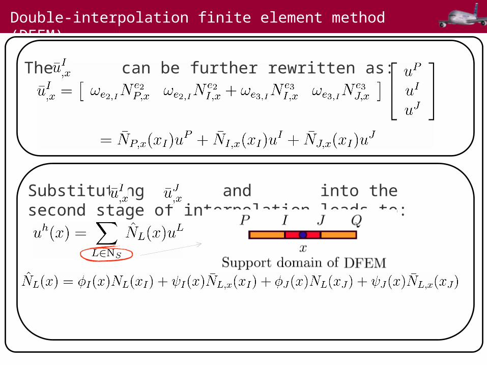
Double-interpolation finite element method (DFEM)
The can be further rewritten as:
Substituting and into the second stage of interpolation leads to:

8
Shape function of DFEM 1D
Derivative of Shape function

9
Double-interpolation finite element method (DFEM)
We perform the same procedure for 2D triangular element:
First stage of interpolation (traditional FEM):
Second stage of interpolation :
are the basis functions with regard to

10
Double-interpolation finite element method (DFEM)
Calculation of Nodal derivatives:
11
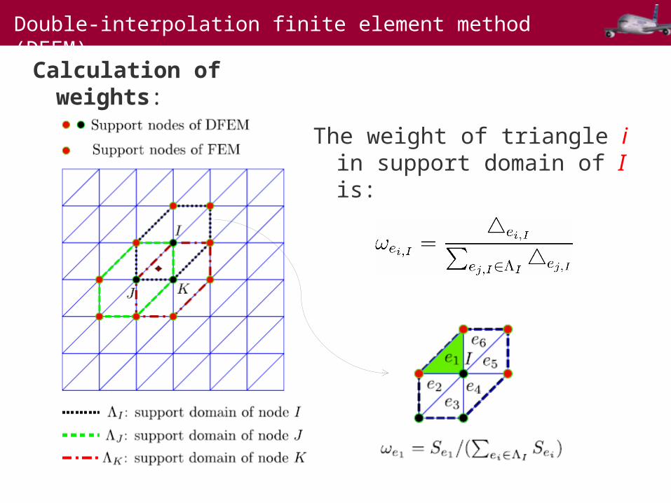
Double-interpolation finite element method (DFEM)
Calculation of weights:
The weight of triangle i in support domain of I is:

12
Double-interpolation finite element method (DFEM)
The basis functions are given as(node I):
are functions w.r.t. , for example:
Area of triangle
13
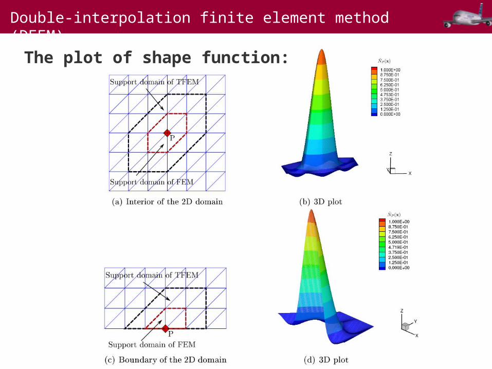
Double-interpolation finite element method (DFEM)
The plot of shape function:

14
The enriched DFEM for crack simulation
DFEM shape function

15
Numerical example of 1D bar
Problem definition: Analytical solutions:
E: Young’s ModulusA: Area of cross sectionL:Length
Displacement(L2) and energy(H1) norm Relative error of stress distribution
16
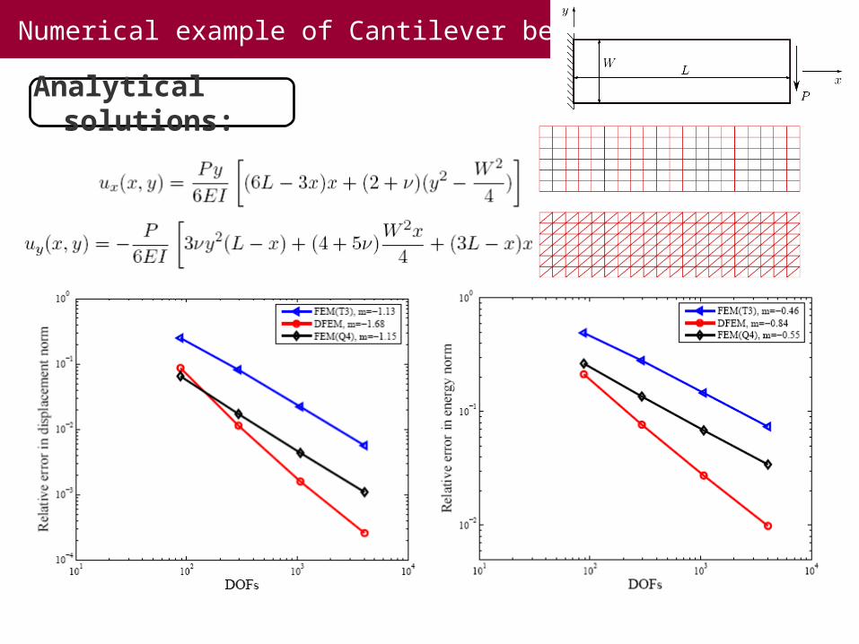
Numerical example of Cantilever beam
Analytical solutions:

17
Numerical example of Mode I crack
Mode-I crack results:a) explicit crack (FEM);b) only Heaviside enrichment;c) full enrichment
18
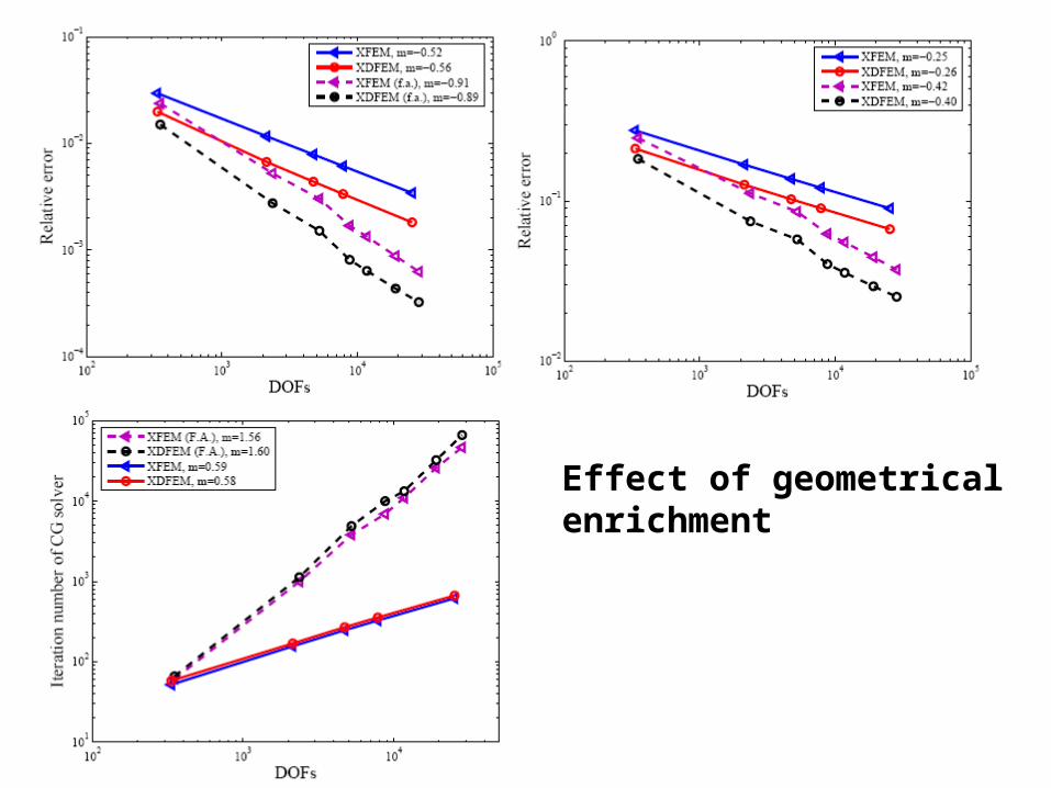
Effect of geometrical enrichment
19
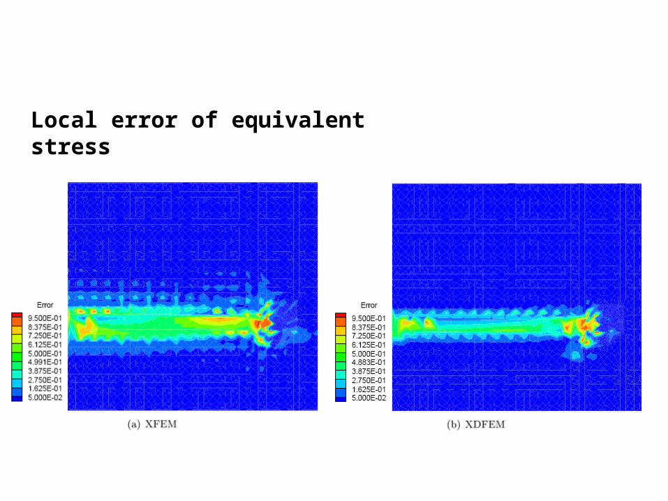
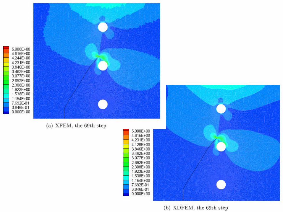
Local error of equivalent stress
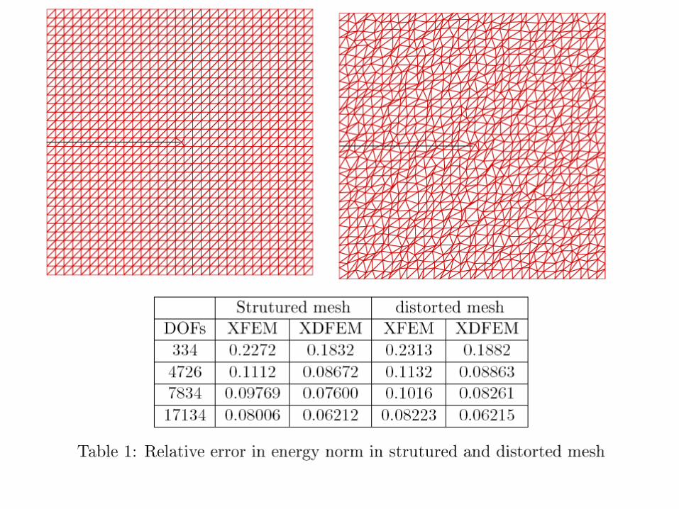
20
21
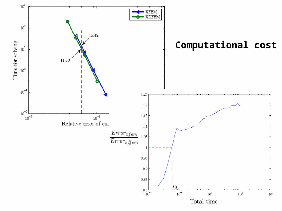
Computational cost

22
23
24

25
Reference
•Moës, N., Dolbow, J., & Belytschko, T. (1999). A finite element method for crack growth without remeshing. IJNME, 46(1), 131–150.
•Melenk, J. M., & Babuška, I. (1996). The partition of unity finite element method: Basic theory and applications. CMAME, 139(1-4), 289–314.
•Laborde, P., Pommier, J., Renard, Y., & Salaün, M. (2005). High-order extended finite element method for cracked domains. IJNME, 64(3), 354–381.
•Wu, S. C., Zhang, W. H., Peng, X., & Miao, B. R. (2012). A twice-interpolation finite element method (TFEM) for crack propagation problems. IJCM, 09(04), 1250055.
•Peng, X., Kulasegaram, S., Bordas, S. P.A., Wu, S. C. (2013). An extended finite element method with smooth nodal stress. http://arxiv.org/abs/1306.0536


