
M Series NMS Network Management User Manual
M Series NMS
Network Management User Manual
Copyright © 2009-2020 FS.COM All Rights Reserved.
S
M Series NMS Network Management User Manual
1
Contents
Preface..........................................................................................................................................................................................................5
1. NMS System Overview.............................................................................................................................................................................7
1.1. NMS System Introduction........................................................................................................................................................... 7
1.2. Functional Characteristics...........................................................................................................................................................7
1.3. Hardware Requirements............................................................................................................................................................. 7
1.4. Networking Mode........................................................................................................................................................................8
2. NMS System Installation and Startup...................................................................................................................................................... 9
2.1. NMS Software Installation...........................................................................................................................................................9
2.2. Key License Validation...............................................................................................................................................................13
2.3. Reinitialize Database................................................................................................................................................................. 13
2.4. Start Server End Program.......................................................................................................................................................... 14
2.5. Log Into Client........................................................................................................................................................................... 15
2.6. Stop Server End Program.......................................................................................................................................................... 16
2.7. NMS Software Upgrade.............................................................................................................................................................17
2.7.1. Database Backup.......................................................................................................................................................... 17
2.7.2. NMS Software Upgrade................................................................................................................................................ 19
2.7.3. Import NMS Data.......................................................................................................................................................... 20
2.7.4. Clear Cache................................................................................................................................................................... 21
3. Interface Operation of NMS System...................................................................................................................................................... 23
3.1. Interface Operation................................................................................................................................................................... 23
3.2. Interface Operation................................................................................................................................................................... 23
3.1.1. Screen Lock................................................................................................................................................................... 23
3.1.2. Exit Logon..................................................................................................................................................................... 24
3.1.3. Change Password......................................................................................................................................................... 25
4. SystemManagement.............................................................................................................................................................................26
4.1. NE(Network Element) Management.........................................................................................................................................26
4.1.1. Add Group.....................................................................................................................................................................26
4.1.2. Add NE...........................................................................................................................................................................28
4.1.3. Modify NE......................................................................................................................................................................29
4.1.4. Synchronize NE............................................................................................................................................................. 29
4.2. FTP Server Configuration.......................................................................................................................................................... 30
M Series NMS Network Management User Manual
2
4.3. SNMP Configuration..................................................................................................................................................................31
4.4. NE IP Configuration................................................................................................................................................................... 32
4.5. Time Configuration................................................................................................................................................................... 33
4.5.1. NTP Server Configuration............................................................................................................................................. 33
4.5.2. NE Time Configuration................................................................................................................................................. 34
4.6. NE-Related Operation................................................................................................................................................................35
4.6.1. NE Basic Information.....................................................................................................................................................35
4.6.2. Configuration Data Saving........................................................................................................................................... 36
4.6.3. Configuration Data Upload.......................................................................................................................................... 37
4.6.4. Configuration Data Download..................................................................................................................................... 38
4.6.5. Restore the Default Configuration............................................................................................................................... 39
4.6.6. NE Log Upload.............................................................................................................................................................. 39
4.6.7. NE Software Upgrade................................................................................................................................................... 40
4.6.8. NE Reboot..................................................................................................................................................................... 41
4.6.9. BSP Upgrade of SC Module (NMU Module)..................................................................................................................41
4.6.10. BSP Upgrade of LCModule (Business Module)..........................................................................................................42
4.6.11. One Touch Inspection.................................................................................................................................................43
4.6.12. Data storage capacity configuration..........................................................................................................................45
5. Alarm Management............................................................................................................................................................................... 47
5.1. Alarm Management Introduction.............................................................................................................................................47
5.2. Alarm Management Main Interface.......................................................................................................................................... 47
5.2.1. Current alarm................................................................................................................................................................47
5.2.2. Historical alarm............................................................................................................................................................. 53
5.3. Alarm Configuration..................................................................................................................................................................54
5.3.1. Alarm Configuration..................................................................................................................................................... 54
5.3.2. Alarm notification configuration..................................................................................................................................56
5.3.3. Alarm notification configuration..................................................................................................................................56
5.3.4. Turn on the alarm sounds.............................................................................................................................................57
5.3.5. Customize alarm sounds.............................................................................................................................................. 58
5.4. Element Event............................................................................................................................................................................58
5.4.1. Introduction to Net Element Events.............................................................................................................................58
5.4.2. Element Event...............................................................................................................................................................58
6. Performance Management....................................................................................................................................................................61
M Series NMS Network Management User Manual
3
6.1. Performance Management Introduction..................................................................................................................................61
6.1.1. filter box........................................................................................................................................................................ 61
6.1.2. Introduction of performance monitoring points.........................................................................................................61
6.1.3. Turn on the performance monitoring point................................................................................................................ 62
6.1.4. Turn off performance monitoring points.....................................................................................................................63
6.1.5. Notes on monitoring performance.............................................................................................................................. 64
6.2. Current Performance Statistics..................................................................................................................................................65
6.2.1. Optical Power Monitoring............................................................................................................................................ 65
6.3. Historical performance statistics...............................................................................................................................................69
6.3.1. Optical power historical performance statistics...........................................................................................................69
7. Log Management...................................................................................................................................................................................72
7.1. Log Management Introduction.................................................................................................................................................72
7.2. Log Query.................................................................................................................................................................................. 72
7.3. Log Maintenance.......................................................................................................................................................................72
7.3.1. Export Log.....................................................................................................................................................................72
7.3.2. Delete Log.....................................................................................................................................................................73
8. Security Management............................................................................................................................................................................75
8.1. Security Management Introduction..........................................................................................................................................75
8.2. User Group Management..........................................................................................................................................................75
8.2.1. Add User Group............................................................................................................................................................ 75
8.2.2. Modify User Group........................................................................................................................................................76
8.2.3. Delete User Group........................................................................................................................................................ 77
8.3. User Management.....................................................................................................................................................................78
8.3.1. Add User........................................................................................................................................................................78
8.3.2. Modify User...................................................................................................................................................................78
8.3.3. Delete User....................................................................................................................................................................80
9. Routine Maintenance.............................................................................................................................................................................81
9.1. Maintenance Requirements......................................................................................................................................................81
9.1.1. Duties of Maintenance Personnel................................................................................................................................ 81
9.1.2. Requirements for the Maintenance Personnel............................................................................................................ 81
9.2. Routine Maintenance Items...................................................................................................................................................... 81
9.2.1. Login the NMS Systemwith Low Level User Identity.................................................................................................. 82
9.2.2. Ping NE..........................................................................................................................................................................83
M Series NMS Network Management User Manual
4
9.2.3. Check Board State.........................................................................................................................................................84
9.2.4. Check Alarm..................................................................................................................................................................84
9.2.5. Check Performance.......................................................................................................................................................86
9.2.6. Query Message Record................................................................................................................................................. 86
9.2.7. Instant Data Backup......................................................................................................................................................87
9.2.8. Use One-Click Inspection..............................................................................................................................................87
9.3. Monthly Routine Maintenance................................................................................................................................................. 88
9.3.1. Data Backup..................................................................................................................................................................88
9.3.2. Performance Acquisition.............................................................................................................................................. 89
9.3.3. Check Hardware Work State.........................................................................................................................................90
9.3.4. History Alarm & Performance Backup.......................................................................................................................... 90
9.3.5. Check Connection of Database.................................................................................................................................... 91
9.4. Quarterly Routine Maintenance................................................................................................................................................91
9.4.1. Proofread NMS Time.....................................................................................................................................................92
9.4.2. Regularly Change Login User Name.............................................................................................................................92
9.4.3. Check Remote Login.....................................................................................................................................................92
9.4.4. Check NMS Function.....................................................................................................................................................92
10. Common Problems.............................................................................................................................................................................. 93
10.1. Server Program Cannot Start.................................................................................................................................................. 93
10.2. Account Cannot Log In............................................................................................................................................................94
10.3. NE Cannot Be Added...............................................................................................................................................................94
10.4. NE Time Is Not Synchronized.................................................................................................................................................. 94
10.5. Network Management Configuration Cannot Be Uploaded..................................................................................................95
10.6. NE Cannot Automatically Report Alarms................................................................................................................................96
10.7. Network elements cannot report performance statistics.......................................................................................................96
10.8. After changing the IP address of the server PC, the running................................................................................................. 97
server cannot login or shuts down automatically...........................................................................................................................97
Abbreviation.............................................................................................................................................................................................. 98
M Series NMS Network Management User Manual
5
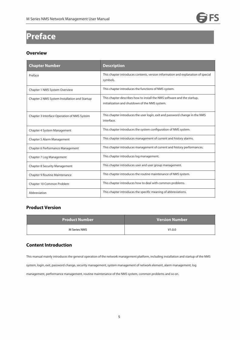
Preface
Overview
Chapter Number Description
Preface This chapter introduces contents, version information and explanation of special
symbols.
Chapter 1 NMS SystemOverview This chapter introduces the functions of NMS system.
Chapter 2 NMS System Installation and Startup This chapter describes how to install the NMS software and the startup,
initialization and shutdown of the NMS system.
Chapter 3 Interface Operation of NMS System This chapter introduces the user login, exit and password change in the NMS
interface.
Chapter 4 SystemManagement This chapter introduces the system configuration of NMS system.
Chapter 5 AlarmManagement This chapter introduces management of current and history alarms.
Chapter 6 Performance Management This chapter introduces management of current and history performances.
Chapter 7 Log Management This chapter introduces logmanagement.
Chapter 8 Security Management This chapter introduces user and user group management.
Chapter 9 Routine Maintenance This chapter introduces the routine maintenance of NMS system.
Chapter 10 Common Problem This chapter introduces how to deal with common problems.
Abbreviation This chapter introduces the specific meaning of abbreviations.
Product Version
Product Number Version Number
M Series NMS V1.0.0
Content Introduction
This manual mainly introduces the general operation of the network management platform, including installation and startup of the NMS
system, login, exit, password change, security management, systemmanagement of network element, alarmmanagement, log
management, performancemanagement, routine maintenance of the NMS system, common problems and so on.
M Series NMS Network Management User Manual
6
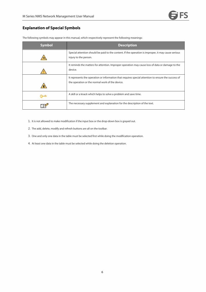
Explanation of Special Symbols
The following symbols may appear in this manual, which respectively represent the followingmeanings:
Symbol Description
Special attention should be paid to the content. If the operation is improper, it may cause serious
injury to the person.
It reminds the matters for attention. Improper operation may cause loss of data or damage to the
device.
It represents the operation or information that requires special attention to ensure the success of
the operation or the normal work of the device.
A skill or a knack which helps to solve a problem and save time.
The necessary supplement and explanation for the description of the text.
1. It is not allowed to make modification if the input box or the drop-down box is grayed out.
2. The add, delete, modify and refresh buttons are all on the toolbar.
3. One and only one data in the table must be selected first while doing the modification operation.
4. At least one data in the table must be selected while doing the deletion operation.

M Series NMS Network Management User Manual
7
1.NMS SystemOverview
1.1.NMS System Introduction
M Series adopts B/S architecture. Only server software needs to be deployed while installing. It uses the browser as the client. HTTP protocol
is used for communication between server and client.
1.2.Functional Characteristics
M Series system adopts advanced and mature network management architecture, which provides a whole set of Java-based cross platform
development tools, modules and API. It can easily integrate with multiple third-party systems. It is an integrated network management
system designed according to the bottom-up rule, which is highly user oriented, carrier-grade and cross-platform. Moreover, it provides a
comprehensive solution for network management.
M Series system can meet various needs of users:
Telecom operators and manufacturers can establish network elements and network management systems.
Service providers can establish network management and operation support systems.
Enterprises and independent software developers can build application program management solutions.
The device managed by M Series system includes all kinds of IP devices in backbone layer, convergence layer and access layer. At present,
the management of soft switch, integrated access server, digital subscriber loop, Ethernet switch, router and ADSL device has been
implemented.
M Series system covers four layers of TMN management:
Network Element Layer;
Network Element Management Layer;
Network Management Layer;
Service Management Layer.
M Series system adopts friendly and full graphical interface, which is simple and easy to operate.
M Series system provides a powerful operation andmanagement tool for network administrators. The network management system can
visually display the network view, monitor and manage multiple network devices in the network, and ensure the reliable, safe and efficient
operation of the network.
1.3.Hardware Requirements

M Series NMS Network Management User Manual
8
Table 1-1 Hardware and Operating System Requirements
Server Configuration Client Configuration (Browser)
Minimum
Configuration
CPU: Frequency 2.0G
Memory: 4G
Hard Disk: >200G
Resolution: 1440x900
Operating System:
Windows Server 2008
CPU: Frequency 2.0G
Memory: 4G
Hard Disk: >100G
Resolution: 1440x900
Operating System: Windows 7
Recommended
Configuration
CPU: Frequency 2.4GHz and above
Memory: >8G
Resolution: 1920x1080
Hard Disk: >500GB
Operating System:
Windows Server 2008, Windows Server 2012
CPU: Frequency 2.4GHz and above
Memory: >8G
Resolution: >1920x1080
Hard Disk: >200GB
Operating System:
Windows 7, Windows 10
The M Series systemwith B/S architecture does not request high requirements for the client; however, there is a certain requirement for the
browser. It is recommended to adopt IE11.0 and above version or Google Chrome.
MSeries management software is not available for Linux computer operation system now. But we can offer related MIB
files for customers.
1.4.NetworkingMode
Figure 1-1 Network Diagram

M Series NMS Network Management User Manual
9
2.NMS System Installation and Startup
2.1.NMS Software Installation
Steps
1. Double click the installation program “NMS_Setup.exe” to enter the installation window. (Click OK when the welcome page pops up.)
Figure 2-1 Software Installation - NMS SetupWizard
2. Click“Next”to enter the next page to configure the installation path of the software. There should be no space, special or Chinese
characters in the installation path. (It is not recommended to locate it in the roof directory or to install it in disks which need system
management permission.)
Figure 2-2 Software Installation-Destination Location
3. After selecting the installation path, click“Next”.

M Series NMS Network Management User Manual
10
Figure 2-3 Software Installation-Select Start Menu Folder
Figure 2-4 Software Installation-Create A Desktop Icon
M Series NMS Network Management User Manual
11
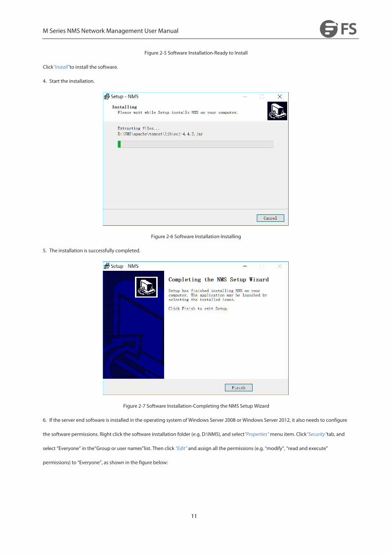
Figure 2-5 Software Installation-Ready to Install
Click“Install”to install the software.
4. Start the installation.
Figure 2-6 Software Installation-Installing
5. The installation is successfully completed.
Figure 2-7 Software Installation-Completing the NMS Setup Wizard
6. If the server end software is installed in the operating system of Windows Server 2008 or Windows Server 2012, it also needs to configure
the software permissions. Right click the software installation folder (e.g. D:\NMS), and select“Properties”menu item. Click“Security”tab, and
select “Everyone” in the“Group or user names”list. Then click “Edit” and assign all the permissions (e.g. “modify”, “read and execute”
permissions) to “Everyone”, as shown in the figure below:

M Series NMS Network Management User Manual
12
Figure 2-8 Software Installation-Permission Settings
7. If there is no “Everyone” in the“Group or user names”list, click “Edit” and“Add” to add“Everyone”and assign all the permissions
to“Everyone”, as shown in the figure below:
Figure 2-9 Add User Permissions
8. If the server end software still has a running problem, then it needs to install the Microsoft Visual C++ runtime. The recommended
installation steps are as follows:
(1) Uninstall M Series network management software.
(2) Install Microsoft Visual C++ runtime vcredist.exe, and restart the equipment after successful installation.
After successful restart of the equipment, install M Series network management software.

M Series NMS Network Management User Manual
13
2.2.Key License Validation
Steps
The key license validation is needed when you use the software for the first time. The license key is included in the CD. (If you can't find the
license key, please contact FS sales manager for help.)
1. Click “Start→ Program→NMS→ NMS Server”, the dialogue box of license validation will pop up when you run the server for the first
time, as shown in the figure below:
Figure 2-10 Key License Validation Interface
2. Input the correct key which you get from FS Sales Manager, and click“Validate”, you can enter the main interface of the server program if
the validation is successful. (Before getting your license key, you should provide your IP address of your computer to our sales manager for
debugging the NMS Sever.)
3. After the key license validation is successful, there is no need to verify it again when you restart the server. If the key license is out of
validity, you need to reapply the key and verify it before you use the NMS software again.
4. If the entity server with NMS software is replaced or the key is out of validity, failure of key license validationmay occur.
2.3.Reinitialize Database
Prerequisite
The NMS server has been shut down.
Related Information
Clear the database and initialize the NMS server.
Steps

M Series NMS Network Management User Manual
14
After the server is shut down, click“Reinitialize NMS”.
After it displays a prompt message, click OK to clear all the data. Only the original default user name and password are retained. The user
needs to add the data back.
Figure 2-11 Server End Software-Reinitialize Database
2.4.Start Server End Program
Steps
1. Click “Start ”→ “Program ”→ “NMS ”→” NMS Server”, then the server interface pops up:
Figure 2-12 Server End Software-Main Interface
2. Double click“Start NMS Server” icon to run the server:

M Series NMS Network Management User Manual
15
When it prompts“Please connect your client to theweb server on port: 9090”, it means that you have successfully started the NMS server.
2.5.Log Into Client
Steps
1. Open a browser.
2. Enter the server IP address XXX.XXX.XXX.XXX:9090. (It is the IP address of NMS server.)
3. Enter correct user name and password (For the administrator, the default login user name is “root”, and the default password is “public”),
as shown in the figure below:
M Series NMS Network Management User Manual
16
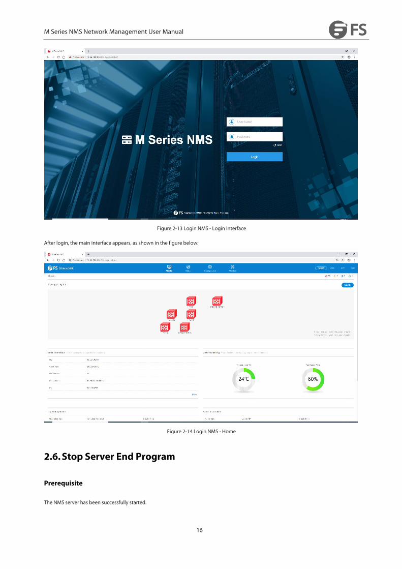
Figure 2-13 Login NMS - Login Interface
After login, the main interface appears, as shown in the figure below:
Figure 2-14 Login NMS - Home
2.6.Stop Server End Program
Prerequisite
The NMS server has been successfully started.

M Series NMS Network Management User Manual
17
Related Information
Shut down the NMS server.
Steps
Click“ShutdownNMS Server“,and the following window pops up:
Figure 2-15 Server End Software-Shutdown NMS Server
Enter the correct user name and password with administrative privileges (By default, the user name is “root”, and the password is “public”).
Click ”OK“, the server will be shut down.
2.7.NMS Software Upgrade
2.7.1. Database Backup
Prerequisite
The NMS server has been shut down.
Related Information
After successful login of DB Tool, the NMS data can be stored in the database under two circumstances of shutting down the server and
starting the server. Meanwhile, the data of the database can also be exported. After successful installation of NMS, select and double
click“NMS” in “All Programs”, then DB Tool interface pops up, as shown in the figure below:

M Series NMS Network Management User Manual
18
Figure 2-16 DB Tool Path
Steps
Double click“DB Tool”, the following interface pops up:
Figure 2-17 DB Tool Login Frame
The initial login account is “root”, and the password is “public”. The following figure shows the interface of successful login:
Figure 2-18 DB Tool Interface
M Series NMS Network Management User Manual
19
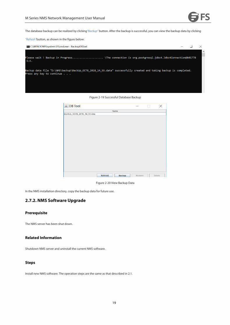
The database backup can be realized by clicking“Backup” button. After the backup is successful, you can view the backup data by clicking
“Refresh”button, as shown in the figure below:
Figure 2-19 Successful Database Backup
Figure 2-20 View Backup Data
In the NMS installation directory, copy the backup data for future use.
2.7.2. NMS Software Upgrade
Prerequisite
The NMS server has been shut down.
Related Information
Shutdown NMS server and uninstall the current NMS software.
Steps
Install new NMS software. The operation steps are the same as that described in 2.1.

M Series NMS Network Management User Manual
20
2.7.3. Import NMS Data
Prerequisite
The NMS server has been shut down.
Related Information
Shutdown NMS server
Steps
Double click“DB Tool” to login DB Tool interface and click“Refresh” to view the data which needs to be restored. Click“Restore”to restore the
database, then the following interface will pop up:
Figure 2-21 View Restored Data
Figure 2-22 Confirm to Restore Database
M Series NMS Network Management User Manual
21
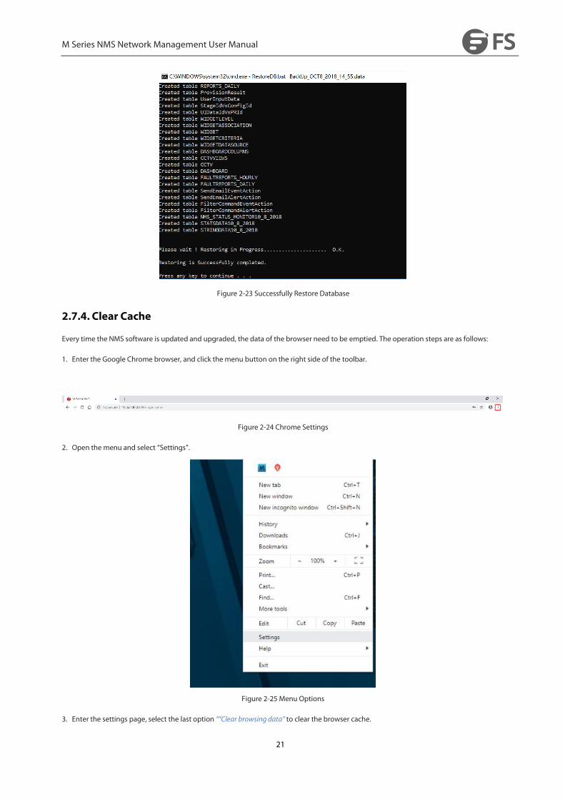
Figure 2-23 Successfully Restore Database
2.7.4. Clear Cache
Every time the NMS software is updated and upgraded, the data of the browser need to be emptied. The operation steps are as follows:
1. Enter the Google Chrome browser, and click the menu button on the right side of the toolbar.
Figure 2-24 Chrome Settings
2. Open the menu and select “Settings”.
Figure 2-25 Menu Options
3. Enter the settings page, select the last option “”Clear browsing data” to clear the browser cache.

M Series NMS Network Management User Manual
22
Figure 2-26 Clear Cache
M Series NMS Network Management User Manual
23
3. Interface Operation of NMS System
3.1. Interface Operation
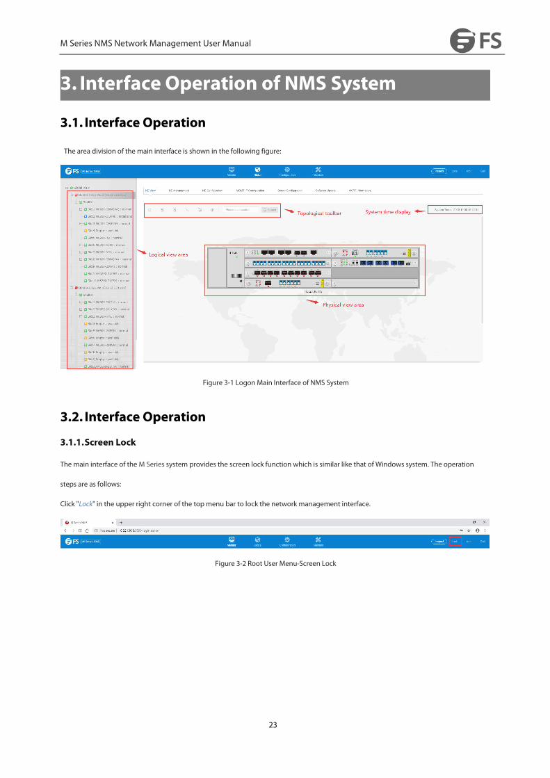
The area division of the main interface is shown in the following figure:
Figure 3-1 Logon Main Interface of NMS System
3.2. Interface Operation
3.1.1.Screen Lock
The main interface of the M Series system provides the screen lock function which is similar like that of Windows system. The operation
steps are as follows:
Click "Lock" in the upper right corner of the topmenu bar to lock the network management interface.
Figure 3-2 Root User Menu-Screen Lock

M Series NMS Network Management User Manual
24
Figure 3-3 Screen Lock Interface
Set automatic screen lock time:
Click the "Configure" button in the topmenu, select "Set Lock Screen Time", the following interface will pop up. (The lock screen function is
off by default)
Figure 3-4 Turn on setting the screen lock time
Select the drop-down menu to enable the lock screen and enter the lock time.
Figure 3-5 Turn on the lock screen to set the lock time
Note: The screen lock time is counted in minutes, and it should be set as not more than 30 minutes (≤30 minutes).
3.1.2.Exit Logon
Click "Quit" in the upper right corner of the topmenu bar, you can exit the login and the following interface will pop up.

M Series NMS Network Management User Manual
25
Figure 3-6 Root User Menu-Exit
3.1.3.Change Password
Click the user“root”in the main interface and select“ Modify Password”, then the following window pops up:
Figure 3-7 Root User Menu-Change Password
Figure 3-8 Change Password
After the password is successfully changed, please login with the new password.
Figure 3-9 Login with New Password

M Series NMS Network Management User Manual
26
4.SystemManagement
4.1.NE(Network Element) Management
4.1.1. Add Group
Click “Global View” --> “Global Configuration” to add user groups. There is no limit to the number of groups (users can create multi-level
groupmenus to differentiate between devices in different rooms).
Figure 4-1 NE Management-Global View
Figure 4-2 NE Management-Add Group

M Series NMS Network Management User Manual
27
It is allowed to create new user group, modify and delete group information and add NE.
Modifying group information includes modifying group name and description of the group.
Figure 4-3 NE Management-Group Node
Figure 4-4 NE Management-Modify Group
All the network elements of the group will be deleted when the user group is deleted.
Figure 4-5 NE Management-Delete Group

M Series NMS Network Management User Manual
28
4.1.2. Add NE
Prerequisite
1. Run the NMS server, and login the browser.
2. The NE has been physically connected with the NMS server.
3. The home page of the NMS has been successfully logged in.
Steps
1.Open the browser to enter the web page of Network Management, log in to Network Management, and in "Global View" -> "Global
Configuration", the Add Device interface will pop up.
2.Enter the network element name, IP address, subnet mask, Trap name and select the Trap host, click "Apply" to complete the creation
(display name is to display the name of the network element, Trap name is to set the name of the Trap host), as shown in the figure.
Figure 4-6 NE Management-Add Equipment
3. (Optional) If you want to modify the attributes of an already created element, click on the element you want to modify, select "NE
Management" on the right navigation bar, and thenmodify the attributes of the modified element.
4. (Optional) To delete an already created element, select "Delete" in the Modify Element field, and click the Apply button in the pop-up box.

M Series NMS Network Management User Manual
29
Figure 4-7 NE Management-NE Nodes
4.1.3. Modify NE
Click the element and select "NE Management" to modify the element's description name.
Figure 4-8 NE Management-Modify NE
4.1.4. Synchronize NE
Click the Element node, select "NEManagement", and in the Synchronization Element, click the "Synchronize NE" synchronization button to
synchronize the status of all network element boards.
M Series NMS Network Management User Manual
30
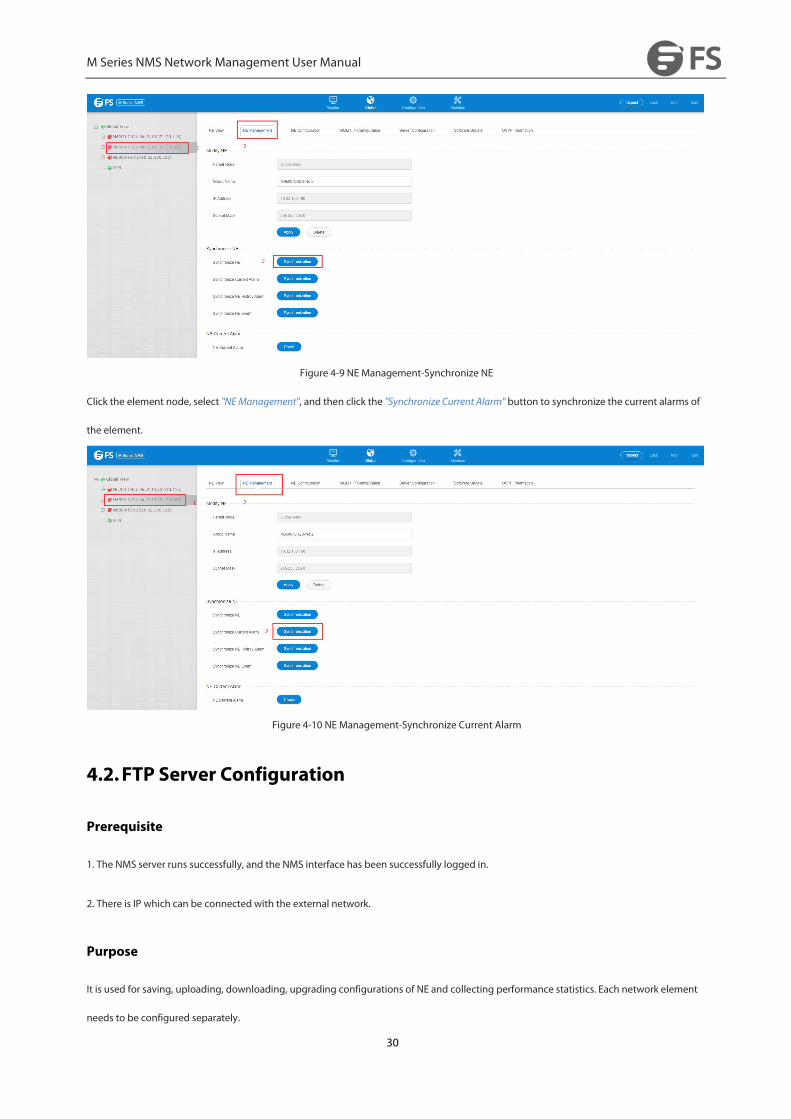
Figure 4-9 NE Management-Synchronize NE
Click the element node, select "NEManagement", and then click the "Synchronize Current Alarm" button to synchronize the current alarms of
the element.
Figure 4-10 NE Management-Synchronize Current Alarm
4.2.FTP Server Configuration
Prerequisite
1. The NMS server runs successfully, and the NMS interface has been successfully logged in.
2. There is IP which can be connected with the external network.
Purpose
It is used for saving, uploading, downloading, upgrading configurations of NE and collecting performance statistics. Each network element
needs to be configured separately.

M Series NMS Network Management User Manual
31
Steps
Select Nethub, click "Server Configuration"-->"FTP Server Configuration" on the navigation bar to enter the FTP configuration interface.
Figure 4-11 FTP Server Configuration
Parameter Description
The system directly assigns local-host to ”Current Value“. The user needs to change it.
For setting values: The system shows the IP of local network card to the user. The user needs to select the IP connected with the
communication of the equipment.
After selecting the appropriate“Set Value” IP, you can click“Apply” to assign the actual IP to“Current Value”.
4.3.SNMP Configuration
Prerequisite
Run the NMS server, login NMS, and successfully add NE.
Related Information
When a NE device is connected with multiple NMS servers, different Trap addresses need to be respectively configured for every NMS
system.
The server is installed under windows. The user needs to turn off the firewall, or set 69 and 16222 ports to penetrate. Otherwise, the upload,
download and alarm event report of SNMP trap may fail.
Steps
Select the network element in the left menu, click "Server Configuration"-->"SNMP Trap Configuration" in the navigation bar.

M Series NMS Network Management User Manual
32
Figure 4-12 SNMP Configuration
When the user needs to add a new IP address, click the "Add" button to bring up the Add page.
Parameter Description
Name: entered by the user. There is no limitation.
Trap Host: IP address of the host to receive Trap information
Trap Port: The port number of the host to receive Trap information is 16222.
4.4.NE IP Configuration
Prerequisite
1. Run the NMS server and login NMS.
2. NE has been successfully created.
3. The physical configuration has been completed.
Related Information
Configure IP address of the Ethernet port.
Steps
Select the network element in the left menu and click "MGMT IP Configuration" in the navigation bar.
M Series NMS Network Management User Manual
33
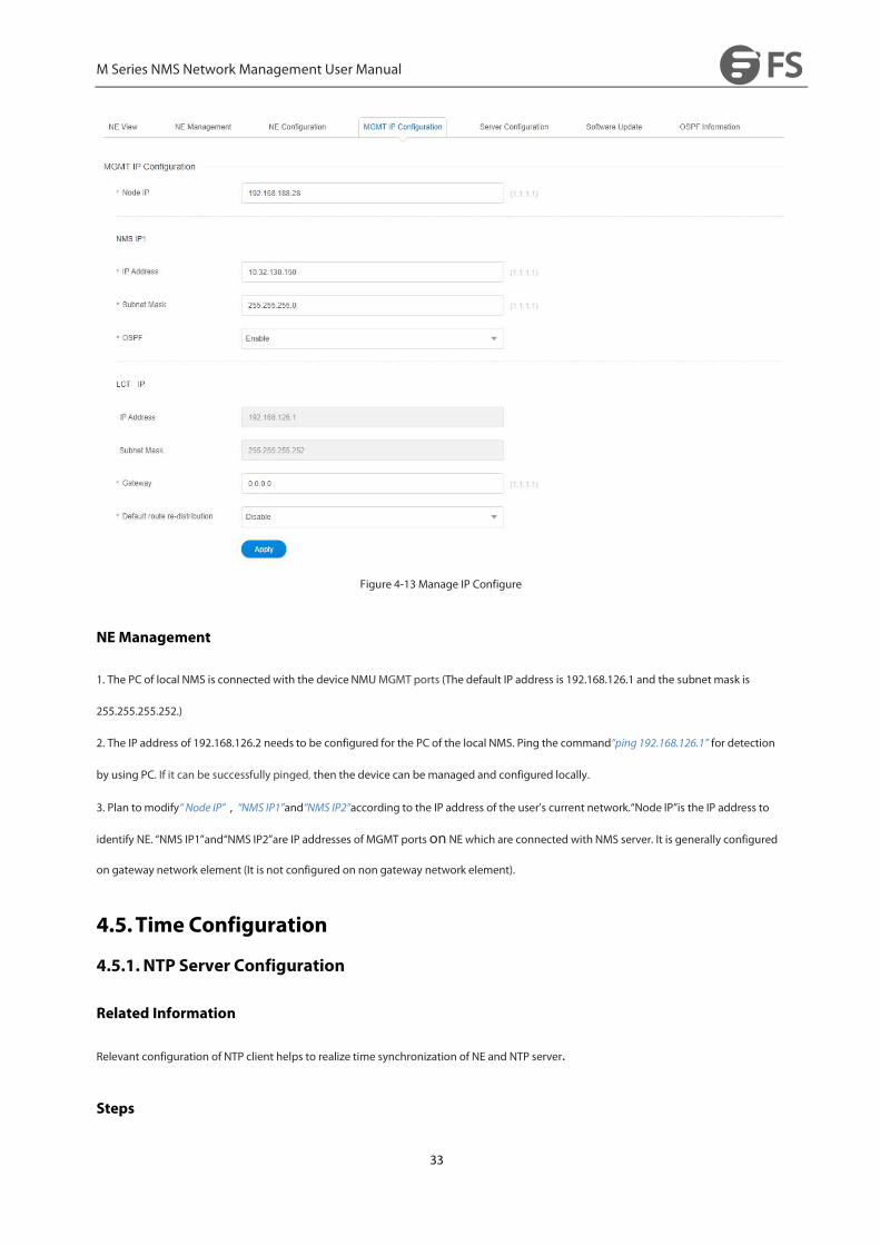
Figure 4-13 Manage IP Configure
NEManagement
1. The PC of local NMS is connected with the device NMUMGMT ports (The default IP address is 192.168.126.1 and the subnet mask is
255.255.255.252.)
2. The IP address of 192.168.126.2 needs to be configured for the PC of the local NMS. Ping the command“ping 192.168.126.1” for detection
by using PC. If it can be successfully pinged, then the device can be managed and configured locally.
3. Plan tomodify“ Node IP”,“NMS IP1”and“NMS IP2”according to the IP address of the user’s current network.“Node IP”is the IP address to
identify NE. “NMS IP1”and“NMS IP2”are IP addresses of MGMT portson NE which are connected with NMS server. It is generally configured
on gateway network element (It is not configured on non gateway network element).
4.5.Time Configuration
4.5.1. NTP Server Configuration
Related Information
Relevant configuration of NTP client helps to realize time synchronization of NE and NTP server.
Steps

M Series NMS Network Management User Manual
34
Select the network element in the left menu, click the navigation bar “Server Configuration" --> "NTP Configuration" button to enter the
configuration interface.
NTP is divided into "server" and "basic information", the server side can display the current configuration of the NTP server information, the
user can click the "Add" button in the toolbar to add a new NTP server.
Figure 4-14 NTP Configuration-Server
Enter the correct server IP, and click “Apply” to complete the adding operation.
The user can select one or multiple options in the check box of the table, and then click “X” button on the toolbar to complete the delete
operation.
In the "Basic Information" user can choose whether to start the NTP service, the interval time is fixed 10, in seconds.
Figure 4-15 NTP Configuration-Basic Information
4.5.2. NE Time Configuration
Prerequisite
1. Run the NMS server and login the NMS.
2. NE has been successfully created.
3. Physical configuration has been completed.

M Series NMS Network Management User Manual
35
Related Information
Configure the time of NE system. By default, GMT is adopted as the standard time zone.
Steps
Select the network element in the left menu, click "NE Configuration" --> "NE Time Configuration" in the navigation bar.
Figure 4-16 NE Time Configuration
Fill in the “NE Current Time” in the correct format (year-month-date hour:minute:second). Click“Apply”to complete the configuration. There is
a promptmessage whether it is successful or failed.
The time zone is Greenwich time, which is eight hours later than Beijing Time. Eight hours needs to be reduced while
making configuration.
4.6.NE-Related Operation
4.6.1. NE Basic Information
Prerequisite
Run the NMS server, login NMS and NE is successfully added.
Related Information
Show NE basic information
Steps
M Series NMS Network Management User Manual
36
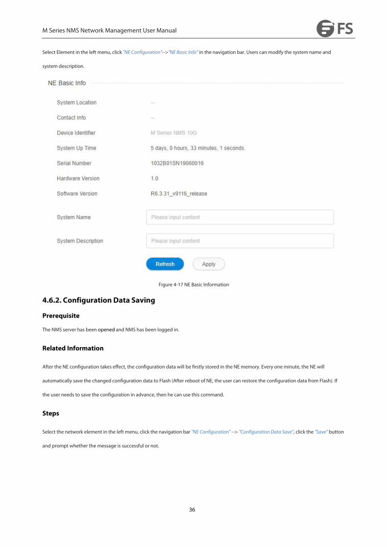
Select Element in the left menu, click "NE Configuration"-->"NE Basic Info" in the navigation bar. Users can modify the system name and
system description.
Figure 4-17 NE Basic Information
4.6.2. Configuration Data Saving
Prerequisite
The NMS server has been opened and NMS has been logged in.
Related Information
After the NE configuration takes effect, the configuration data will be firstly stored in the NE memory. Every oneminute, the NE will
automatically save the changed configuration data to Flash (After reboot of NE, the user can restore the configuration data from Flash). If
the user needs to save the configuration in advance, then he can use this command.
Steps
Select the network element in the left menu, click the navigation bar "NE Configuration" --> "ConfigurationData Save", click the "Save" button
and prompt whether the message is successful or not.

M Series NMS Network Management User Manual
37
Figure 4-18 Configuration Data Saving
4.6.3. Configuration Data Upload
Prerequisite
1. Run the NMS server and login NMS.
2. FTP has been successfully configured.
Related Information
Upload the current NE configuration to the NMS system.
Steps
1, select the network element in the left menu, click the navigation bar "NE Configuration" --> "Configuration Data Upload".
2、Click "Upload", enter the file name (32-bit combination of numbers, letters, underscores and underscores "_"), and then you will be
prompted for success or failure.
3, the configuration file will be saved in the following directory: server installation root directory NMS --> TFTP --> config.
M Series NMS Network Management User Manual
38
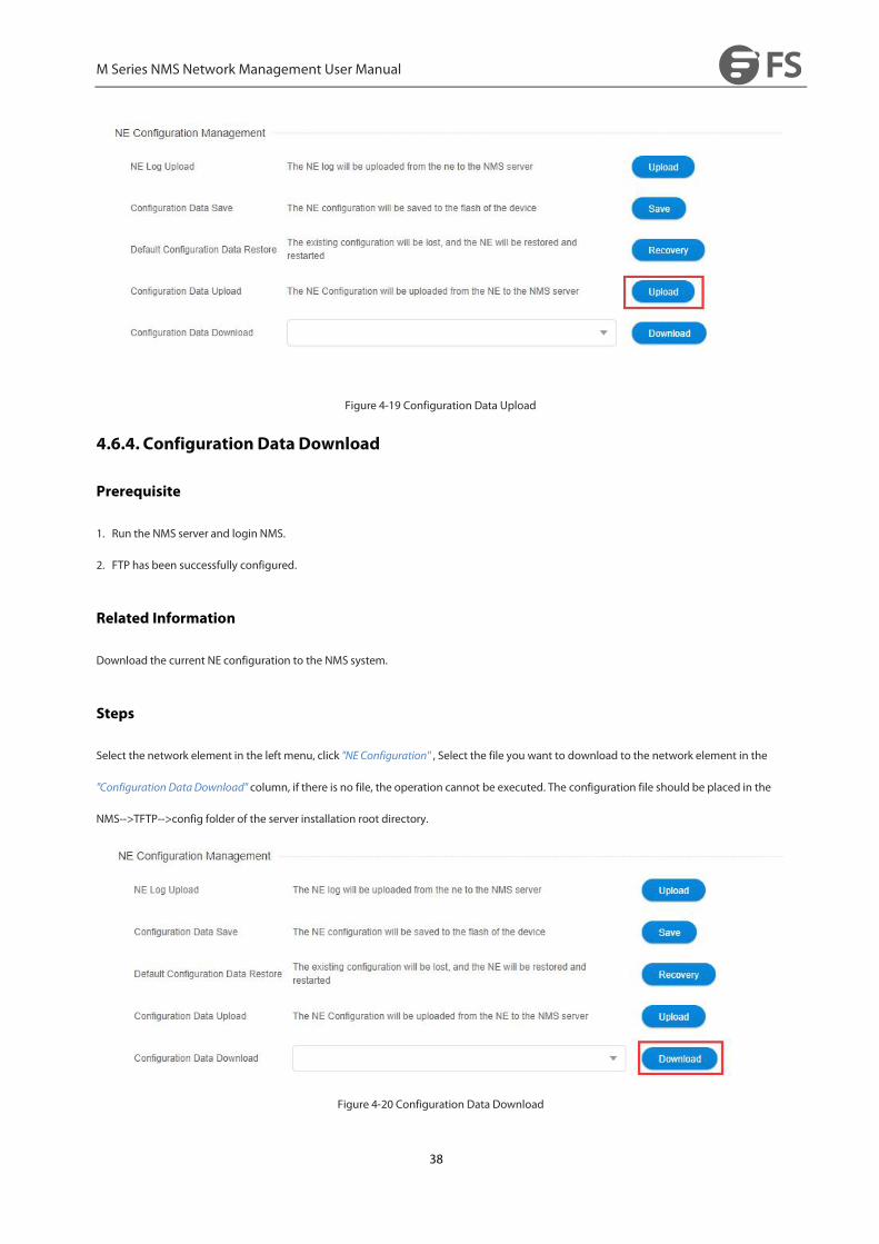
Figure 4-19 Configuration Data Upload
4.6.4. Configuration Data Download
Prerequisite
1. Run the NMS server and login NMS.
2. FTP has been successfully configured.
Related Information
Download the current NE configuration to the NMS system.
Steps
Select the network element in the left menu, click "NE Configuration" , Select the file you want to download to the network element in the
"Configuration DataDownload" column, if there is no file, the operation cannot be executed. The configuration file should be placed in the
NMS-->TFTP-->config folder of the server installation root directory.
Figure 4-20 Configuration Data Download
M Series NMS Network Management User Manual
39
4.6.5. Restore the Default Configuration
Related Information
Restore NE configuration to default configuration.
Steps
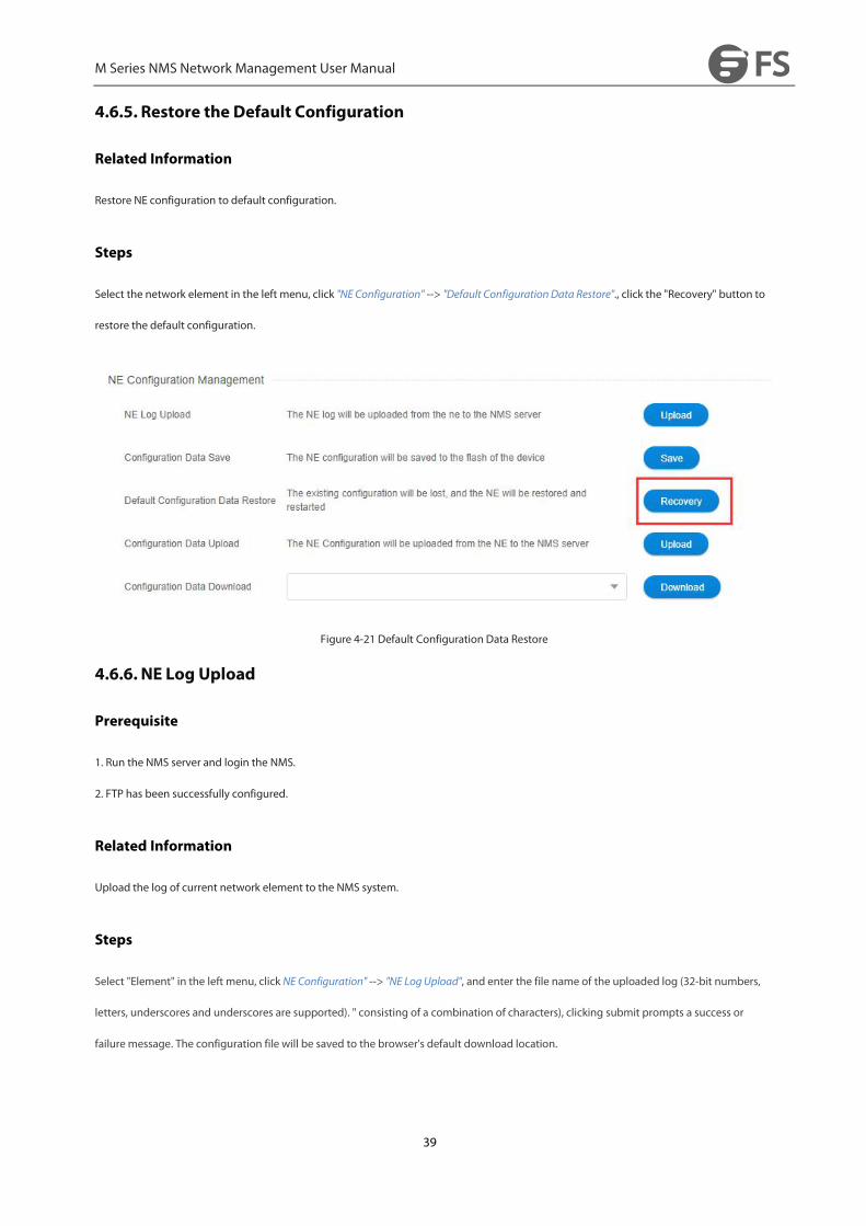
Select the network element in the left menu, click "NE Configuration" --> "Default ConfigurationData Restore"., click the "Recovery" button to
restore the default configuration.
Figure 4-21 Default Configuration Data Restore
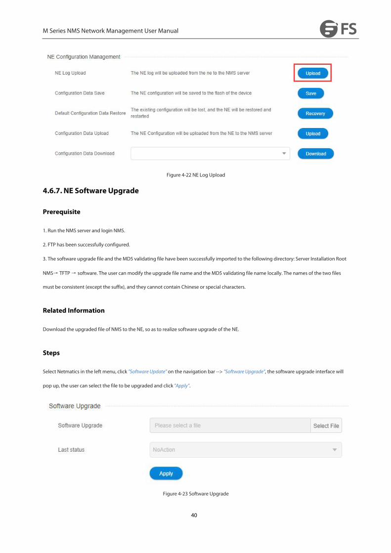
4.6.6. NE Log Upload
Prerequisite
1. Run the NMS server and login the NMS.
2. FTP has been successfully configured.
Related Information
Upload the log of current network element to the NMS system.
Steps
Select "Element" in the left menu, click NE Configuration" --> "NE LogUpload", and enter the file name of the uploaded log (32-bit numbers,
letters, underscores and underscores are supported). " consisting of a combination of characters), clicking submit prompts a success or
failure message. The configuration file will be saved to the browser's default download location.
M Series NMS Network Management User Manual
40
Figure 4-22 NE Log Upload
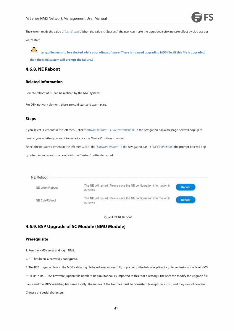
4.6.7. NE Software Upgrade
Prerequisite
1. Run the NMS server and login NMS.
2. FTP has been successfully configured.
3. The software upgrade file and the MD5 validating file have been successfully imported to the following directory: Server Installation Root
NMS→ TFTP→ software. The user can modify the upgrade file name and the MD5 validating file name locally. The names of the two files
must be consistent (except the suffix), and they cannot contain Chinese or special characters.
Related Information
Download the upgraded file of NMS to the NE, so as to realize software upgrade of the NE.
Steps
Select Netmatics in the left menu, click "Software Update" on the navigation bar --> "Software Upgrade", the software upgrade interface will
pop up, the user can select the file to be upgraded and click "Apply".
Figure 4-23 Software Upgrade
M Series NMS Network Management User Manual
41
The system reads the value of“Last Status”. When the value is “Success”, the user can make the upgraded software take effect by clod start or
warm start.
tar.gz file needs to be selected while upgrading software. There is no need upgradingMD5 file. (If this file is upgraded,
then the NMS systemwill prompt the failure.)
4.6.8. NE Reboot
Related Information
Remote reboot of NE can be realized by the NMS system.
For OTN network element, there are cold start and warm start.
Steps
If you select "Element" in the left menu, click "Software Update" --> "NEWarmReboot" in the navigation bar, a message box will pop up to
remind you whether you want to restart, click the "Restart" button to restart.
Select the network element in the left menu, click the "Software Update" in the navigation bar --> "NE ColdReboot", the prompt box will pop
up whether you want to reboot, click the "Restart" button to restart.
Figure 4-24 NE Reboot
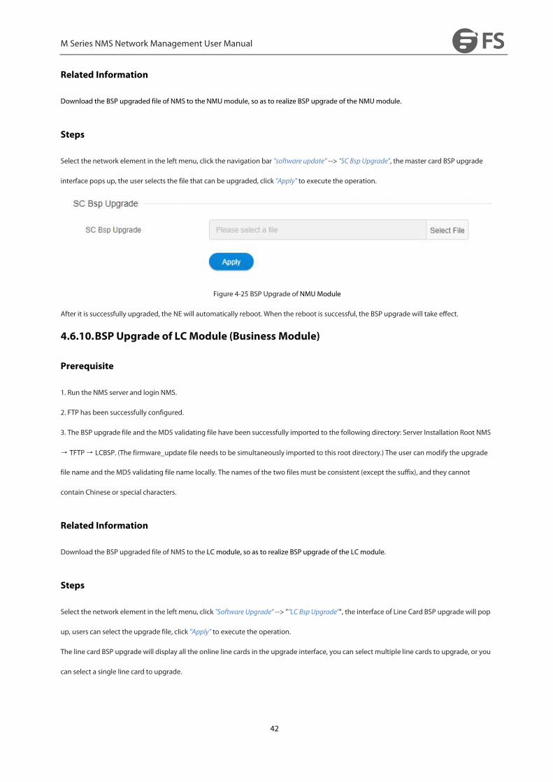
4.6.9. BSP Upgrade of SCModule (NMUModule)
Prerequisite
1. Run the NMS server and login NMS.
2. FTP has been successfully configured.
3. The BSP upgrade file and the MD5 validating file have been successfully imported to the following directory: Server Installation Root NMS
→ TFTP→ BSP. (The firmware_update file needs to be simultaneously imported to this root directory.) The user can modify the upgrade file
name and the MD5 validating file name locally. The names of the two files must be consistent (except the suffix), and they cannot contain
Chinese or special characters.
M Series NMS Network Management User Manual
42
Related Information
Download the BSP upgraded file of NMS to the NMUmodule, so as to realize BSP upgrade of the NMUmodule.
Steps
Select the network element in the left menu, click the navigation bar "software update" --> "SC Bsp Upgrade", the master card BSP upgrade
interface pops up, the user selects the file that can be upgraded, click "Apply" to execute the operation.
Figure 4-25 BSP Upgrade of NMUModule
After it is successfully upgraded, the NE will automatically reboot. When the reboot is successful, the BSP upgrade will take effect.
4.6.10.BSP Upgrade of LCModule (Business Module)
Prerequisite
1. Run the NMS server and login NMS.
2. FTP has been successfully configured.
3. The BSP upgrade file and the MD5 validating file have been successfully imported to the following directory: Server Installation Root NMS
→ TFTP→ LCBSP. (The firmware_update file needs to be simultaneously imported to this root directory.) The user can modify the upgrade
file name and the MD5 validating file name locally. The names of the two files must be consistent (except the suffix), and they cannot
contain Chinese or special characters.
Related Information
Download the BSP upgraded file of NMS to the LC module, so as to realize BSP upgrade of the LCmodule.
Steps
Select the network element in the left menu, click "Software Upgrade" --> ""LC BspUpgrade"", the interface of Line Card BSP upgrade will pop
up, users can select the upgrade file, click "Apply" to execute the operation.
The line card BSP upgrade will display all the online line cards in the upgrade interface, you can select multiple line cards to upgrade, or you
can select a single line card to upgrade.
M Series NMS Network Management User Manual
43
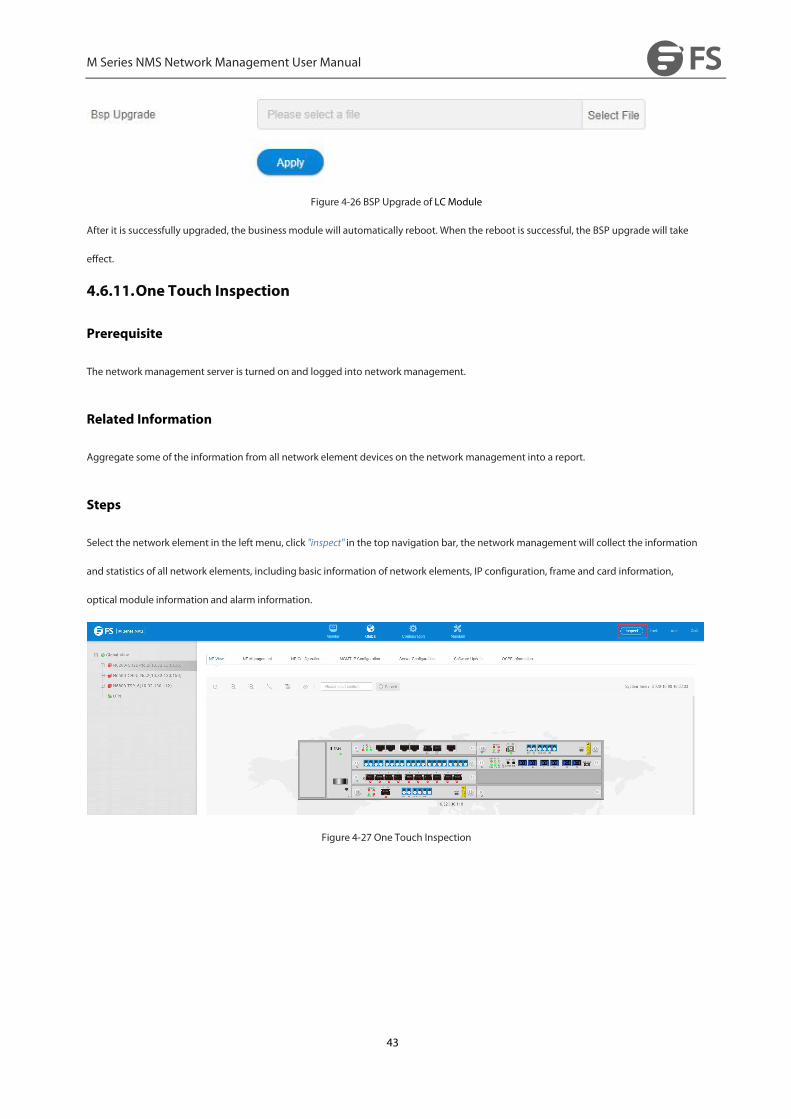
Figure 4-26 BSP Upgrade of LCModule
After it is successfully upgraded, the business module will automatically reboot. When the reboot is successful, the BSP upgrade will take
effect.
4.6.11.One Touch Inspection
Prerequisite
The network management server is turned on and logged into network management.
Related Information
Aggregate some of the information from all network element devices on the network management into a report.
Steps
Select the network element in the left menu, click "inspect" in the top navigation bar, the network management will collect the information
and statistics of all network elements, including basic information of network elements, IP configuration, frame and card information,
optical module information and alarm information.
Figure 4-27 One Touch Inspection
M Series NMS Network Management User Manual
44
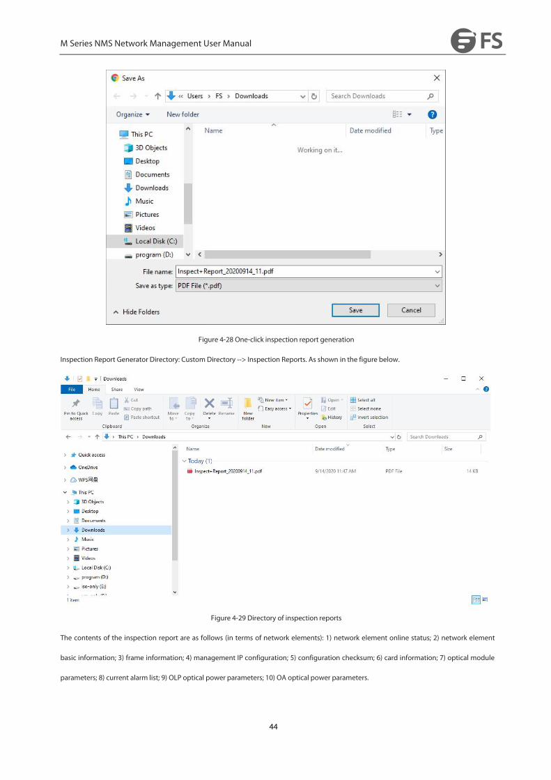
Figure 4-28 One-click inspection report generation
Inspection Report Generator Directory: CustomDirectory --> Inspection Reports. As shown in the figure below.
Figure 4-29 Directory of inspection reports
The contents of the inspection report are as follows (in terms of network elements): 1) network element online status; 2) network element
basic information; 3) frame information; 4) management IP configuration; 5) configuration checksum; 6) card information; 7) optical module
parameters; 8) current alarm list; 9) OLP optical power parameters; 10) OA optical power parameters.

M Series NMS Network Management User Manual
45
Figure 4-30 Content format of inspection reports
4.6.12.Data storage capacity configuration
Prerequisite
The network management server is turned on and logged into network management.
Related Information
Displays performance statistics, historical alarms, logging, number of network element event data and can configure data storage capacity
Steps
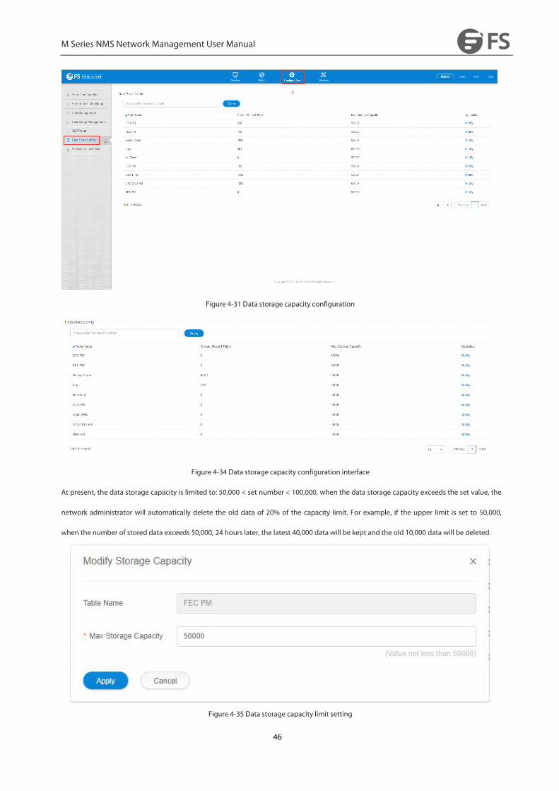
Click "Configuration" on the top navigation bar --> "Data Store Config", you can view the current performance statistics, historical alarms, logs
and the total number of element events, and can set the capacity limit.
M Series NMS Network Management User Manual
46
Figure 4-31 Data storage capacity configuration
Figure 4-34 Data storage capacity configuration interface
At present, the data storage capacity is limited to: 50,000 < set number < 100,000, when the data storage capacity exceeds the set value, the
network administrator will automatically delete the old data of 20% of the capacity limit. For example, if the upper limit is set to 50,000,
when the number of stored data exceeds 50,000, 24 hours later, the latest 40,000 data will be kept and the old 10,000 data will be deleted.
Figure 4-35 Data storage capacity limit setting
M Series NMS Network Management User Manual
47
5.AlarmManagement
5.1.AlarmManagement Introduction
The alarmmanagement function is a functional group that manages the faults occurring in various network devices managed by the
network management system during the operation of the system. Themanaged faults are commonly known as alarms.
The network management alarmmanagement function of the managed fault contains two types and four levels: equipment alarms and
communication alarms of two types; emergency, major, minor, warning four levels.
5.2.AlarmManagementMain Interface
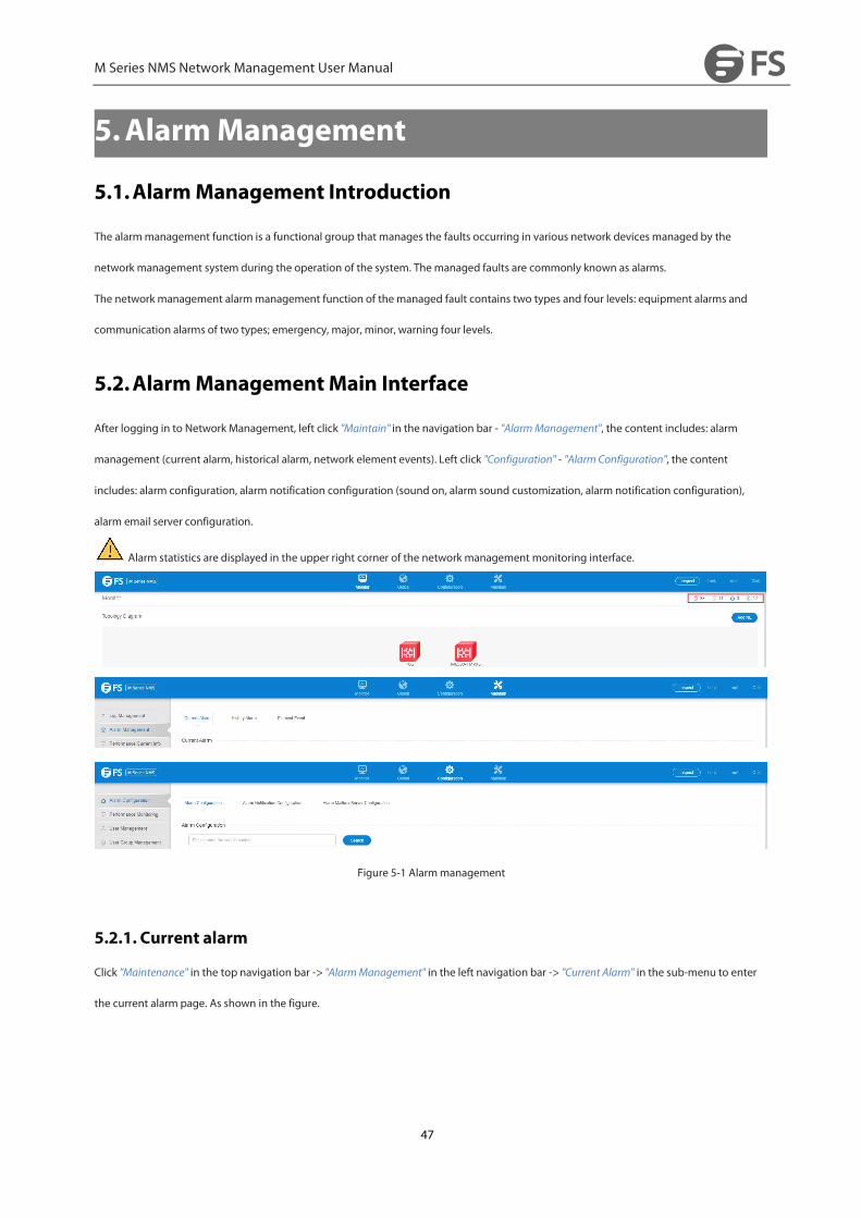
After logging in to Network Management, left click "Maintain" in the navigation bar - "AlarmManagement", the content includes: alarm
management (current alarm, historical alarm, network element events). Left click "Configuration" - "Alarm Configuration", the content
includes: alarm configuration, alarm notification configuration (sound on, alarm sound customization, alarm notification configuration),
alarm email server configuration.
Alarm statistics are displayed in the upper right corner of the network management monitoring interface.
Figure 5-1 Alarmmanagement
5.2.1. Current alarm
Click "Maintenance" in the top navigation bar -> "AlarmManagement" in the left navigation bar -> "Current Alarm" in the sub-menu to enter
the current alarm page. As shown in the figure.

M Series NMS Network Management User Manual
48
Figure 5-2 Current alarm
The area at the bottom right of the table allows you to filter the number of alerts displayed on the current page, and the number of alerts
per page can be adjusted to 10, 20, 50 and 100.
Figure 5-3 Displays the current number of alarms
The middle right area under the navigation bar is "Ack", "Unack",button, which functions as.
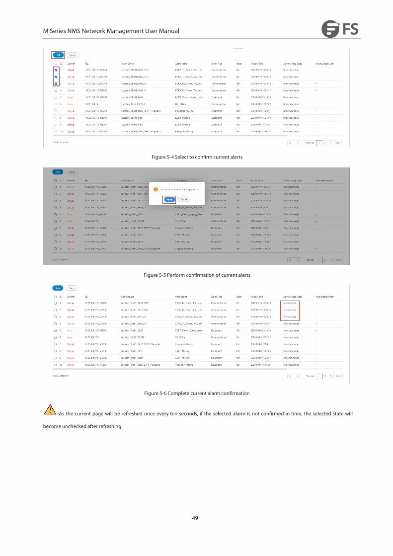
The "Ack" button is used to confirm the selected alert. By selecting the check box to the left of the selected alert, and clicking the "Ack"
button, all the selected alerts will be in the status of confirmation. The confirmation status of the alert is "Acknowledge", The "Ack" button in
the operation bar changes to "Unack". The specific operation is as follows: Select the alarm to be confirmed → Click "Ack" button → Click
"Apply"→ Alarm confirmation.
As the current page will be refreshed once every ten seconds, if the selected alarm is not confirmed in time, the selected state will
become unchecked after refreshing.
M Series NMS Network Management User Manual
49
Figure 5-4 Select to confirm current alerts
Figure 5-5 Perform confirmation of current alerts
Figure 5-6 Complete current alarm confirmation
As the current page will be refreshed once every ten seconds, if the selected alarm is not confirmed in time, the selected state will
become unchecked after refreshing.
M Series NMS Network Management User Manual
50
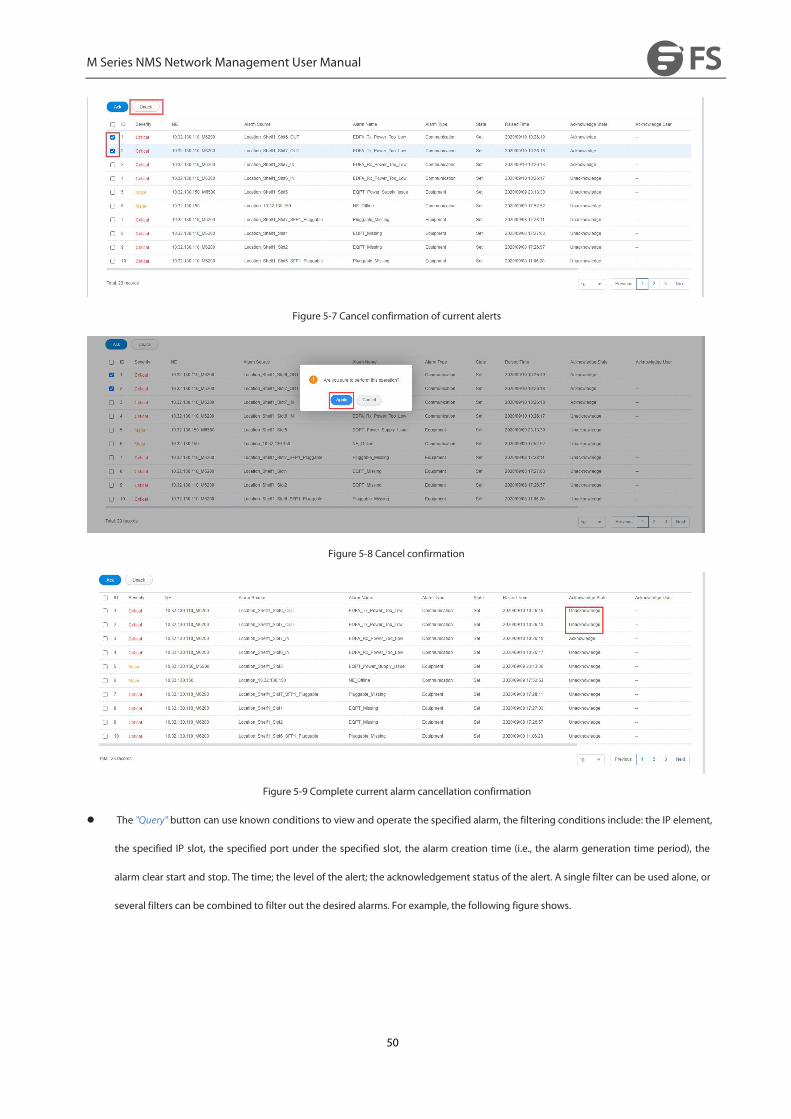
Figure 5-7 Cancel confirmation of current alerts
Figure 5-8 Cancel confirmation
Figure 5-9 Complete current alarm cancellation confirmation
The "Query" button can use known conditions to view and operate the specified alarm, the filtering conditions include: the IP element,
the specified IP slot, the specified port under the specified slot, the alarm creation time (i.e., the alarm generation time period), the
alarm clear start and stop. The time; the level of the alert; the acknowledgement status of the alert. A single filter can be used alone, or
several filters can be combined to filter out the desired alarms. For example, the following figure shows.

M Series NMS Network Management User Manual
51
Figure 5-10 IP Filtering Current Alerts
Figure 5-11 Slotted port filtering current alarms
Figure 5-12 Alert level and acknowledgement status filtering of current alerts
Filter IP, Slot, Port, The way to filter IP, Slot, Port is IP→ Slot→ Port, or IP→ Slot, or IP. select Slot or Port individually is not selectable.
The "Auto Refresh" button is a left/right moving button (when clicked, it switches from refresh to close or from close to refresh), and
the current page is refreshed every 10 seconds when it is in the refresh state, and it is not refreshed when it is in the close state.
The top area of the table is a search function that automatically retrieves all alerts containing the specified content by typing it in, as shown
in the following figure.
Figure 5-13 Search current alerts
M Series NMS Network Management User Manual
52
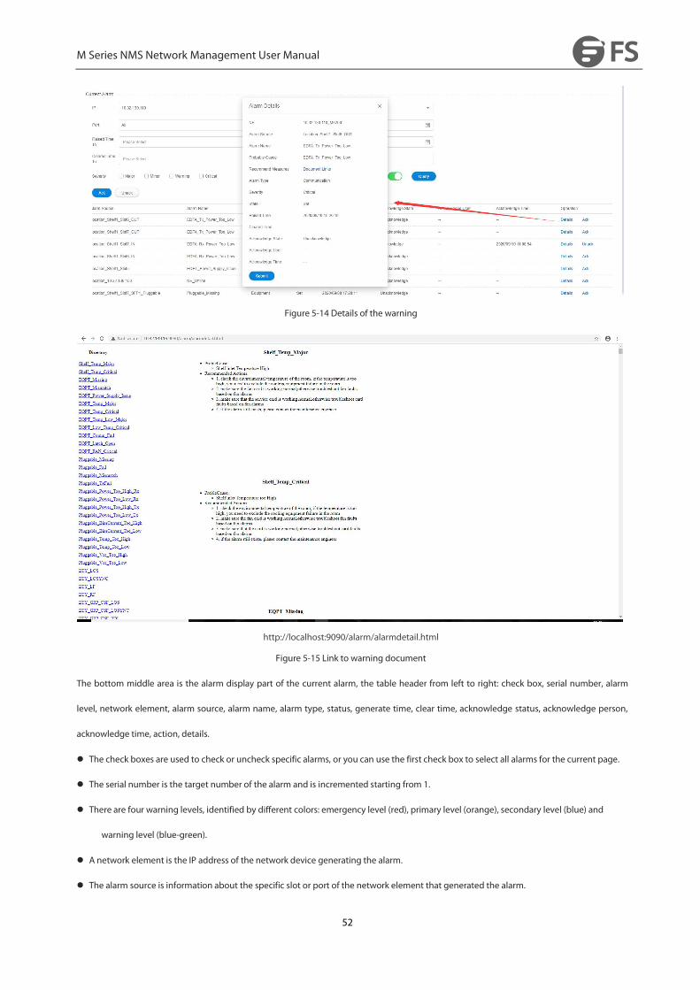
Figure 5-14 Details of the warning
http://localhost:9090/alarm/alarmdetail.html
Figure 5-15 Link to warning document
The bottom middle area is the alarm display part of the current alarm, the table header from left to right: check box, serial number, alarm
level, network element, alarm source, alarm name, alarm type, status, generate time, clear time, acknowledge status, acknowledge person,
acknowledge time, action, details.
The check boxes are used to check or uncheck specific alarms, or you can use the first check box to select all alarms for the current page.
The serial number is the target number of the alarm and is incremented starting from 1.
There are four warning levels, identified by different colors: emergency level (red), primary level (orange), secondary level (blue) and
warning level (blue-green).
A network element is the IP address of the network device generating the alarm.
The alarm source is information about the specific slot or port of the network element that generated the alarm.
M Series NMS Network Management User Manual
53
Alarm name, alarm type, status, generation time, confirmation status, confirmation person, confirmation time content is relatively simple,
do not repeat here.
Details, when clicked, this alert will open a popup window to display the details of the alert. The details include: network element, alarm
source, alarm name, alarm reason, recommended action, alarm type, alarm level, status, generation time, clear time, confirmation
status, acknowledgement person, and acknowledgement time. The network element, alarm source, alarm name, alarm type, status,
generation time, clearing time, confirmation status, confirming person, confirmation time and the contents of the table header are
the same, the cause of the alarm refers to the cause of the current alarm, and the recommended measures are links. page, you can see
the possible causes of alarms and recommended actions to help engineers troubleshoot problems.
Confirmation has the same function as "Confirm" and "Cancel" buttons respectively, but the icon buttons in the operation bar are only
available for alarms on the line.
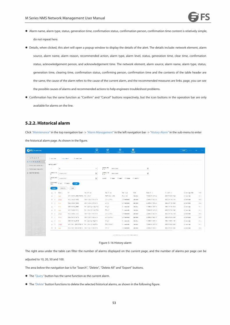
5.2.2. Historical alarm
Click "Maintenance" in the top navigation bar -> "AlarmManagement" in the left navigation bar -> "History Alarm" in the sub-menu to enter
the historical alarm page. As shown in the figure.
Figure 5-16 History alarm
The right area under the table can filter the number of alarms displayed on the current page, and the number of alarms per page can be
adjusted to 10, 20, 50 and 100.
The area below the navigation bar is for "Search", "Delete", "Delete All" and "Export" buttons.
The "Query" button has the same function as the current alarm.
The "Delete" button functions to delete the selected historical alarms, as shown in the following figure.

M Series NMS Network Management User Manual
54
Figure 5-17 Delete historical alerts
The "Delete All" button deletes all history alarms.
The "Export" button is used to export all alarms to a local file: click Export to download the file to a local file with the default name
"HistoryAlarm.xlsx".
Figure 5-18 Exporting Historical Alerts
The area below the navigation bar is the alarm display part of the historical alarm, the table header from left to right: Serial Number, NE,
Alarm Source, Alarm Name, Alarm Type, Severity, status, Raised Time, Cleared Time, Acknowledge State,Acknowledge User, Acknowledge
Time.. (The function is the same as the current alarm, so I won't repeat it)
There are three alarm clearing states (auto clear, manual clear, and synchronous clear); the acknowledgement state is
"acknowledgement" only; there are two types of acknowledgement (auto acknowledgement, acknowledgement by current logged in user,
such as root).
5.3. Alarm Configuration
5.3.1. Alarm Configuration
Click "Configuration" in the top navigation bar -> "Alarm Configuration" in the left navigation bar -> "Alarm Configuration" in the sub-menu to
enter the alarm configuration page. As shown in the figure.

M Series NMS Network Management User Manual
55
Figure 5-19 Alarm Configuration
The number of alerts displayed on the current page can be filtered in the right-hand area under the Alert Configuration table.
Figure 5-20 Number of alarm configuration displays
The left side of the table is the search function. By typing in the specified content and clicking on the search element, you can get all the
alarms containing that content, as shown in the following figure.
Figure 5-21 Alert Configuration Search
The header of the alarm configuration table data is: alarm name, alarm level configuration, alarm mask configuration.
Alert name: All alerts on the net meta are under the alert name.
Alarm level configuration: can set the specified alarm level for the specified alarm, there are emergency, major, minor, warning four kinds
of levels can be selected (there is no setting before the default level for the alarm level).
M Series NMS Network Management User Manual
56
Alarm shield configuration: the specified alarm can be shielded, after shielding, when the network element produces this alarm will not
be displayed on the network management (the default configuration for all alarms are not shielded).
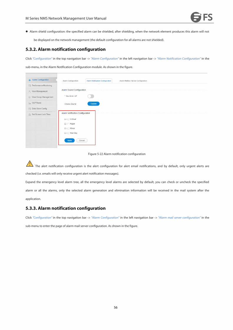
5.3.2. Alarm notification configuration
Click "Configuration" in the top navigation bar -> "Alarm Configuration" in the left navigation bar -> "Alarm Notification Configuration" in the
sub-menu, in the Alarm Notification Configurationmodule. As shown in the figure.
Figure 5-22 Alarm notification configuration
The alert notification configuration is the alert configuration for alert email notifications, and by default, only urgent alerts are
checked (i.e. emails will only receive urgent alert notification messages).
Expand the emergency level alarm tree, all the emergency level alarms are selected by default, you can check or uncheck the specified
alarm or all the alarms, only the selected alarm generation and elimination information will be received in the mail system after the
application.
5.3.3. Alarm notification configuration
Click "Configuration" in the top navigation bar -> "Alarm Configuration" in the left navigation bar -> "Alarm mail server configuration" in the
sub-menu to enter the page of alarmmail server configuration. As shown in the figure.

M Series NMS Network Management User Manual
57
Figure 5-23 Alert Mail Server Configuration
The function of alarm mailbox server configuration is: configure a mailbox as server mailbox, and then change information in navigation
bar→Configuration→User management→(Assign user column) and fill in an email address to receive alarm notification. In this way, the
alarm generated by the network element (after the configuration in the previous section) will be sent to the mailbox server through the
mailbox server to receive the alarm email.
Different types of mailboxes have different STMP addresses and port numbers, so please check the server mailbox type and SMTP
information before setting the server mailbox.
5.3.4. Turn on the alarm sounds
Click "Configuration" in the top navigation bar -> "Alarm Configuration" in the left navigation bar -> "Alarm Notification Configuration" in the
sub-menu, in the alarm sound configurationmodule. As shown in the figure.
Figure 5-24 Alarm sound configuration
M Series NMS Network Management User Manual
58
Turning on the sound function means that when there is an alarm on the network management, when this function is turned on, the
network management server will continue to sound an alarm, indicating that there is an alarm on the network management. At present, the
network management only has the function to turn on and off.
There are four kinds of alarm sound, corresponding to emergency alarm, major alarm, minor alarm and warning alarm, but after the
network management open sound only the sound of the highest level alarm; When the alarm level changes alarm sound type also changes
(for example, the current alarm level for emergency and major, the prompt for the highest level of emergency alarm sound, if the
emergency level alarm disappears, it will be converted to major level alarm sound).
5.3.5. Customize alarm sounds
Alarm sound customization means that customers can set different alarm tones for different types of alarms according to their own needs.
5.4.Element Event
5.4.1. Introduction to Net Element Events
The network element event function is a function that manages the SNC protection inversions that occur in various network devices
managed by the network management system during system operation. The managed inversion functions are collectively called events.
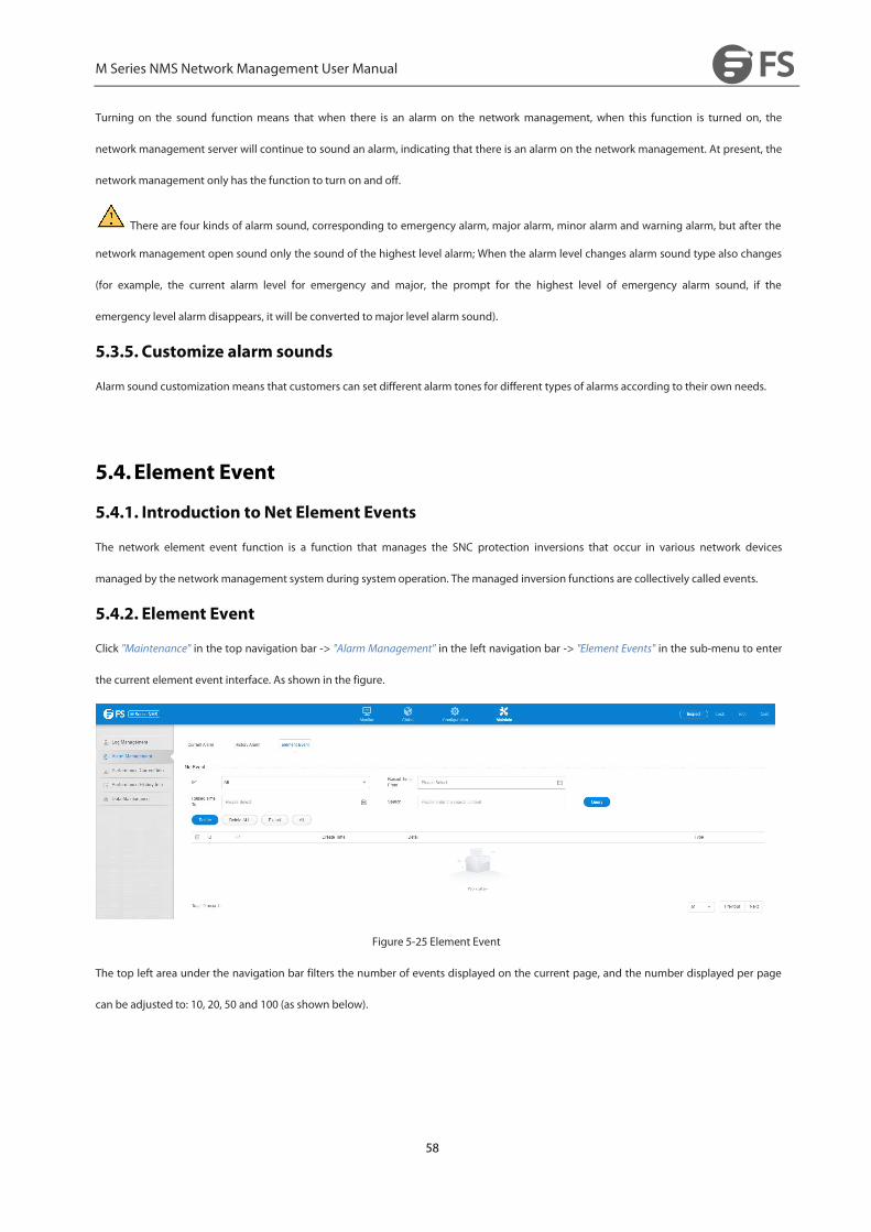
5.4.2. Element Event
Click "Maintenance" in the top navigation bar -> "Alarm Management" in the left navigation bar -> "Element Events" in the sub-menu to enter
the current element event interface. As shown in the figure.
Figure 5-25 Element Event
The top left area under the navigation bar filters the number of events displayed on the current page, and the number displayed per page
can be adjusted to: 10, 20, 50 and 100 (as shown below).

M Series NMS Network Management User Manual
59
Figure 5-26 Show number of current events
The area under the navigation bar is for "Search", "Delete", "Export", "Delete All" buttons, whose functions are.
The "Query" button function can be used to view and operate on a specified event using known conditions, including: network element
IP, event creation start and end time (i.e., event generation time period); a single filtering condition can be used alone, or several
filtering conditions can be used in combination, thus Filter out the required events. For example, the figure below shows.
Figure 5-27 IP Query Network Element Event
Figure 5-28 Create Time Query Net Element Events
The "Delete" button function is to delete the selected element event as shown in the following figure.
Figure 5-29 Deleting a Net Element Event

M Series NMS Network Management User Manual
60
The "Export" button is used to export all element events: click Export to download the file to a local file with the default name
"NEevents.xlsx".
Figure 5-30 Exporting Net Elements Events
The "Delete All" button is used to delete all the element events.
The upper right area under the navigation bar is the search function: you can get all the events that contain the content by entering the
specified content, as shown in the following figure.
Figure 5-31 Searching for a net meta event
In the middle of the lower part of the table is the element event display section, with the following headers from left to right: check box, ID,
IP, generation time, details, and element event type.
The checkbox is used to check or uncheck the specified event, or you can use the first checkbox to select the current page event in full.
ID is the event's numeric target number, increasing sequentially from 1.
IP is the IP of the network device that generated the event.
The details are Show Working TP ID, Protect TP ID, Reverse Cause, and Current Service Channel.
The generation time and the network element time type are not described here.
M Series NMS Network Management User Manual
61
6.PerformanceManagementThe first step in performance management is to go to the performance monitoring point management interface and open the performance
monitoring point that you want to monitor.
6.1.Performance Management Introduction
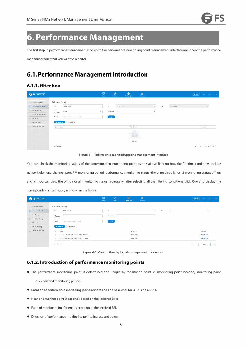
6.1.1. filter box
Figure 6-1 Performancemonitoring point management interface
You can check the monitoring status of the corresponding monitoring point by the above filtering box, the filtering conditions include
network element, channel, port, PM monitoring period, performance monitoring status (there are three kinds of monitoring status: off, on
and all, you can view the off, on or all monitoring status separately), after selecting all the filtering conditions, click Query to display the
corresponding information, as shown in the figure.
Figure 6-2 Monitor the display of management information
6.1.2. Introduction of performancemonitoring points
The performance monitoring point is determined and unique by monitoring point id, monitoring point location, monitoring point
direction andmonitoring period.
Location of performance monitoring point: remote end and near-end (for OTUk and ODUk).
Near-end monitor point (near-end): based on the received BIP8.
Far-endmonitor point (far-end): according to the received BEI.
Direction of performance monitoring points: ingress and egress.

M Series NMS Network Management User Manual
62
Monitoring period: 15 minutes, 24 hours.
6.1.3. Turn on the performancemonitoring point
When the current 15-minute performance monitoring point is opened, all the performance monitoring parameters under the performance
monitoring point are opened at the same time, so only after the performance monitoring point is opened can the current performance
statistics be viewed. As the performance monitoring operation will affect the performance of a network element, it supports up to 500
performance monitoring points (including 15 minutes and 24 hours) for a single network element, more than 500 points will show failed
operation.
Figure 6-3 Opening of monitoring points
Figure 6-4 Single monitoring point open
To batch open multiple data, you can select them by using the checkboxes in front of you, then click the button on top of the table (Open
Performance Monitor) to open the selected Performance Monitor, as shown in the figure.
Figure 6-5 Batch monitoring points open
M Series NMS Network Management User Manual
63
Select multiple performance monitors that are already open, then select Open Performance Monitor and click Confirm to show no changes
as shown.
Figure 6-6 No modifications to monitor point status
6.1.4. Turn off performancemonitoring points
When the current 15-minute performance monitoring point is closed, 24-hour performance monitoring is automatically closed by default,
and all the performance monitoring parameters under this performance monitoring point are closed at the same time, so when the
performancemonitoring point is closed, you can't see the current performance statistics, as shown in the figure.
Figure 6-7 Closure of monitoring points
Each monitor point is modified in state via the buttons behind it, and can be de-activated individually, as shown in the figure.
Figure 6-8 Single monitoring point off
To close the batch operation for multiple data, you can click the button (Close Performance Monitor) on the top of the table to close the
selected Performance Monitor, as shown in the figure.
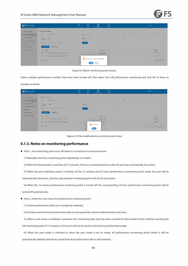
M Series NMS Network Management User Manual
64
Figure 6-9 Batch monitoring point closure
Select multiple performance monitors that have been turned off, then select Turn off performance monitoring and click OK to show no
changes as shown.
Figure 6-10 No modifications to monitor point status
6.1.5. Notes onmonitoring performance
Note 1, the monitoring point turns off when it is turned on in several situations.
(1) Manually close the monitoring points individually or in batch.
(2) When the boardmode is switched, all 15 minutes, 24 hours monitoring points under the port are automatically shut down.
(3) When the port switching mode is switched, all the 15 minutes and 24 hours performance monitoring points under the port will be
automatically shut down, only the optical power monitoring point will not be shut down.
(4) When the 15-minute performance monitoring point is turned off, the corresponding 24-hour performance monitoring point will be
turned off automatically.
Note 2, when the user closes the performancemonitoring point.
(1) Current performance data can no longer be obtained.
(2) Already saved historical performance data can be queried by network administrators and users.
(3) When a user issues a shutdown command, the monitoring data that has been counted for that period of time (without reaching the
full monitoring cycle of 15 minutes or 24 hours) will not be saved to the historical performance data.
(4) When the port mode is switched or when the port mode is set to empty, all performance monitoring points below it will be
automatically deleted (previously stored historical performance data is still retained).
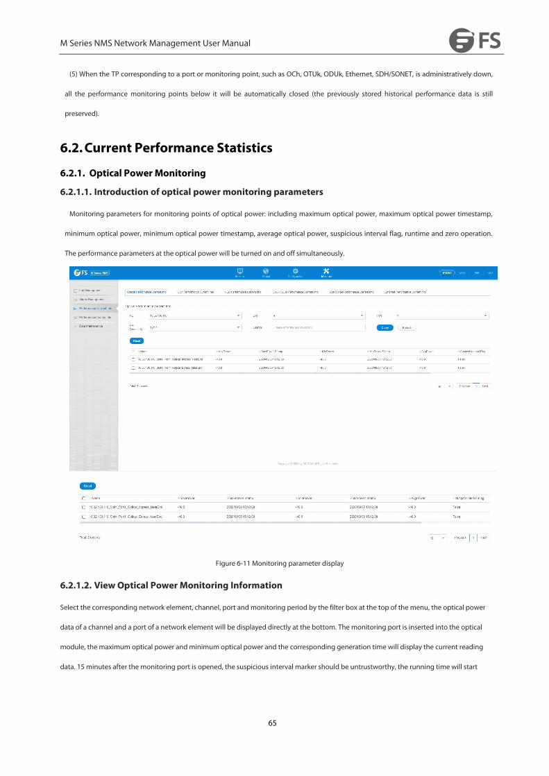
M Series NMS Network Management User Manual
65
(5) When the TP corresponding to a port or monitoring point, such as OCh, OTUk, ODUk, Ethernet, SDH/SONET, is administratively down,
all the performance monitoring points below it will be automatically closed (the previously stored historical performance data is still
preserved).
6.2.Current Performance Statistics
6.2.1. Optical PowerMonitoring
6.2.1.1. Introduction of optical power monitoring parameters
Monitoring parameters for monitoring points of optical power: including maximum optical power, maximum optical power timestamp,
minimum optical power, minimum optical power timestamp, average optical power, suspicious interval flag, runtime and zero operation.
The performance parameters at the optical power will be turned on and off simultaneously.
Figure 6-11 Monitoring parameter display
6.2.1.2. View Optical Power Monitoring Information
Select the corresponding network element, channel, port and monitoring period by the filter box at the top of the menu, the optical power
data of a channel and a port of a network element will be displayed directly at the bottom. The monitoring port is inserted into the optical
module, the maximum optical power andminimum optical power and the corresponding generation time will display the current reading
data. 15 minutes after the monitoring port is opened, the suspicious interval marker should be untrustworthy, the running time will start

M Series NMS Network Management User Manual
66
counting from 0, after 900 seconds, the suspicious interval marker will become trustworthy, the running time will start counting again from
0, the previous 15 minutes data will automatically enter the history data. Medium.
Figure 6-12 Minute monitoring point data display
When the 24-hour monitoring port is first opened, the suspicious interval marker should be untrustworthy and the run time should start
counting from 0. After waiting for 86400 seconds, the suspicious interval marker will become trustworthy and the run time will start
counting again from 0. The 24-hour data from the previous entry is automatically entered into the historical data.
Figure 6-13 24-hour monitoring point data display
6.2.1.3. Zeroing of optical power monitoring data
When the current optical power monitoring point wants to zero out and start monitoring again, the 15 minutes and 24 hours operations are
the same. Take 15 minutes as an example, you can click the zero operation at the end of each monitoring for single zero, or select the top
box for batch zero, as shown in the figure.

M Series NMS Network Management User Manual
67
Figure 6-14 Optical power batch zeroing
Then click the Apply button, as shown in the figure, the display operation is successful, then you need to click the Refresh button to refresh
the whole page, this time the suspicious interval marker will change from the original credible to untrustworthy, the running time will start
from 0 to count again, the maximum optical power timestamp and minimum optical power timestamp will be updated to read the optical
power of the latest time point, the maximum optical power andminimum optical power is also updated to the latest time point to read the
value.
Figure 6-15 Zeroing operation successful
6.2.1.4. Optical power monitoring data display "--"
For ports:
(1) When no module is inserted into the port, that is, when the optical module is not in place but the port is enabled.
(2) When there is a module but mismatch on the port and the port is enabled.
At this time, the maximum and minimum optical power will be displayed "-", the maximum and minimum optical power time-stamp is
displayed "- - - / - - / - - : - - : - -", the suspicious interval is marked as untrustworthy, the runtime display is normal, or counting from 0. As
shown.
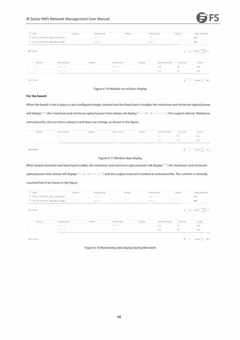
M Series NMS Network Management User Manual
68
Figure 6-16 Module out of place display
For the board:
When the board is not in place or pre-configured empty channel and the board port is enable, the maximum and minimum optical power
will display "--", the maximum and minimum optical power time-stamp will display "- - - - / - - / - - : - - - : - -", the suspect interval. Marked as
untrustworthy, the run time is always 0 and does not change, as shown in the figure.
Figure 6-17 Monitor data display
When boardmismatch and board port enable, the maximum and minimum optical power will display "--", the maximum and minimum
optical power time-stampwill display "- - - / - - / - - : - - : - -", and the suspect interval is marked as untrustworthy. The runtime is normally
counted from 0 as shown in the figure.
Figure 6-18 Monitoring data display during Mismatch
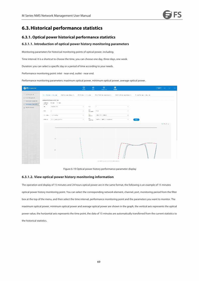
M Series NMS Network Management User Manual
69
6.3.Historical performance statistics
6.3.1. Optical power historical performance statistics
6.3.1.1. Introduction of optical power history monitoring parameters
Monitoring parameters for historical monitoring points of optical power, including.
Time interval: It is a shortcut to choose the time, you can choose one day, three days, one week.
Duration: you can select a specific day or a period of time according to your needs.
Performancemonitoring point: inlet - near end, outlet - near end.
Performancemonitoring parameters: maximum optical power, minimum optical power, average optical power.
Figure 6-19 Optical power history performance parameter display
6.3.1.2. View optical power history monitoring information
The operation and display of 15 minutes and 24 hours optical power are in the same format, the following is an example of 15 minutes
optical power history monitoring point. You can select the corresponding network element, channel, port, monitoring period from the filter
box at the top of the menu, and then select the time interval, performancemonitoring point and the parameters you want to monitor. The
maximum optical power, minimum optical power and average optical power are shown in the graph, the vertical axis represents the optical
power value, the horizontal axis represents the time point, the data of 15 minutes are automatically transferred from the current statistics to
the historical statistics.

M Series NMS Network Management User Manual
70
Figure 6-20 15-minute chart data display
The historical performance statistics of optical power can also be presented in the form of a table, click on the table, the interface shown in
the figure.
Figure 6-21 15-minute table screen display
Select the time interval and duration, click Query, and a history of all optical power currently recorded by this port will appear, as shown in
the screen.
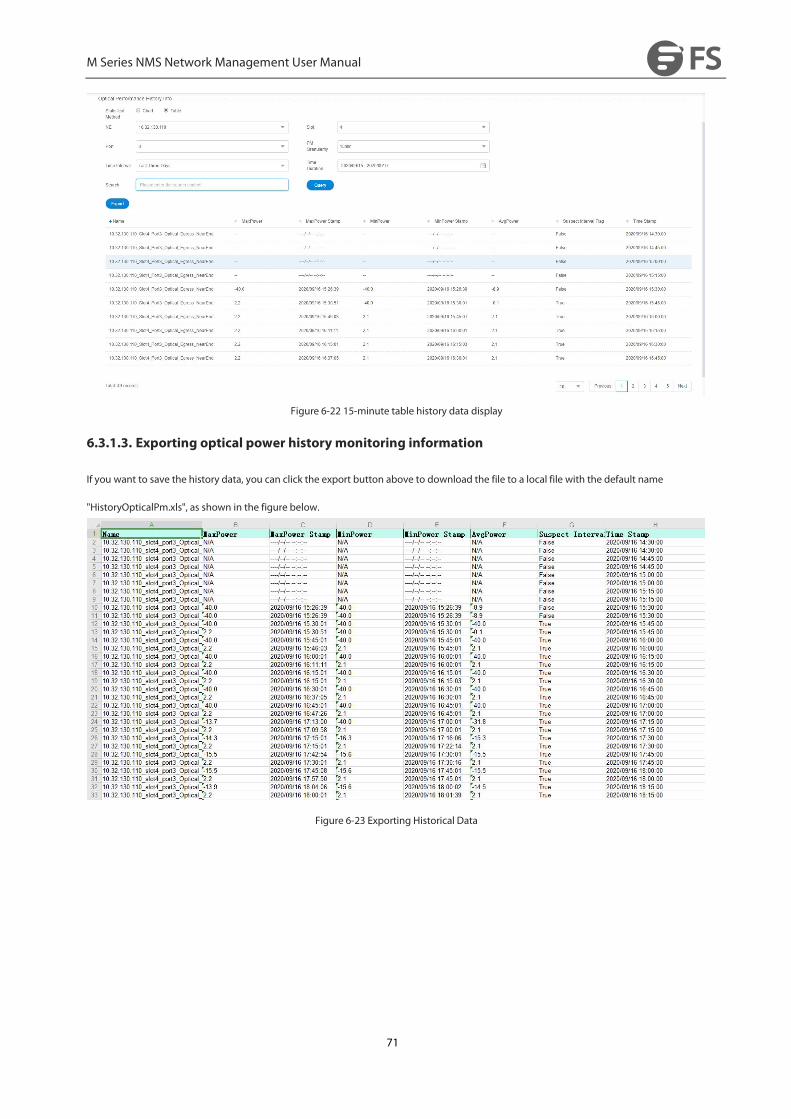
M Series NMS Network Management User Manual
71
Figure 6-22 15-minute table history data display
6.3.1.3. Exporting optical power history monitoring information
If you want to save the history data, you can click the export button above to download the file to a local file with the default name
"HistoryOpticalPm.xls", as shown in the figure below.
Figure 6-23 Exporting Historical Data

M Series NMS Network Management User Manual
72
7. LogManagement
7.1.LogManagement Introduction
There are three types of logs:
The operation log records the user’s operation information, including log ID, operation level, user name, operation name, host
address, command function, detailed information, operation result, failure reason, access mode, operation object, operation start
time, operation end time and associated log information.
The security log records the user’s login status, including log ID, user name, host address, log name, operation time, access mode
and detailed information.
The system log records the completion of the timed task of the server, including log ID, level, source, log name, detailed
information, host address, operation start time, operation end time and associated log information.
7.2.Log Query
Click "Maintenance" on the top navigation bar -> "Log Management" to enter the page, as shown in the figure below.
Figure 7-1 Log Management
A piece of log information will generate every time when the user add, modify and delete the data. That is to say, except for query operation,
every operation the user performed will lead in the generation of log information.
7.3.LogMaintenance
7.3.1. Export Log
Check the check box in the upper left corner, click the "Export" button to export the selected logs, and click Save As to put the exported logs
in a custom directory.

M Series NMS Network Management User Manual
73
Figure 7-2 Export Log
Figure 7-1 Exported Logs
7.3.2. Delete Log
Select the form in the data you want to delete (the deletion log itself will also generate a "deletion log" of the log record), click the "Delete"
button will prompt the user to confirm the deletion operation again. The following figure.
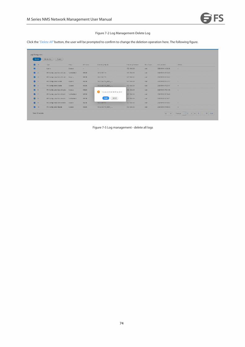
M Series NMS Network Management User Manual
74
Figure 7-2 Log Management-Delete Log
Click the "Delete All" button, the user will be prompted to confirm to change the deletion operation here. The following figure.
Figure 7-5 Logmanagement - delete all logs
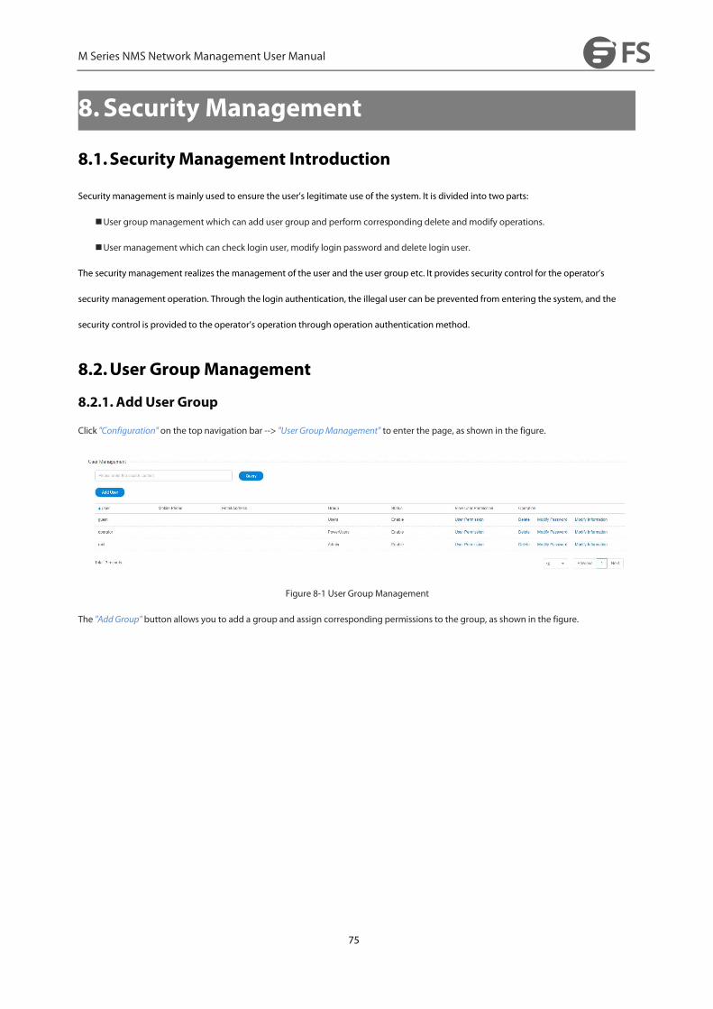
M Series NMS Network Management User Manual
75
8.Security Management
8.1.Security Management Introduction
Security management is mainly used to ensure the user’s legitimate use of the system. It is divided into two parts:
User group management which can add user group and perform corresponding delete andmodify operations.
User management which can check login user, modify login password and delete login user.
The security management realizes the management of the user and the user group etc. It provides security control for the operator’s
security management operation. Through the login authentication, the illegal user can be prevented from entering the system, and the
security control is provided to the operator’s operation through operation authentication method.
8.2.User GroupManagement
8.2.1. Add User Group
Click "Configuration" on the top navigation bar --> "User GroupManagement" to enter the page, as shown in the figure.
Figure 8-1 User Group Management
The "Add Group" button allows you to add a group and assign corresponding permissions to the group, as shown in the figure.

M Series NMS Network Management User Manual
76
Figure 8-2 User GroupManagement-Add Group
8.2.2.Modify User Group
Select the "Group Permissions" column in the table in the user group management page --> "Operation Permission Assignment" button to
modify the operation permissions of this user group, as shown in the figure.
Figure 8-3 User Group Management-Modify Group Right

M Series NMS Network Management User Manual
77
Select the "Group Permissions" column in the user group management page table --> "Node Permission Assignment" button to assign
different node devices to the user, as shown in the figure.
Figure 8-1 User Group Management-Unassigned Users
Note: If the user group does not have "device management" privilege, it will have no privilege to assign node privilege to the user group.
There are three types of permission settings, a tickmeans operable, a x means visible and inoperable, a null means invisible. The default
user cannot bemodified.
8.2.3. Delete User Group
The "Delete" button on the user groupmanagement screen can delete the corresponding data, and you will be prompted again if you want
to confirm the deletion, as shown in the figure below.
Figure 8-2 User GroupManagement-Delete Group
Admin, Power-users and Users are default groups. They cannot be deleted.
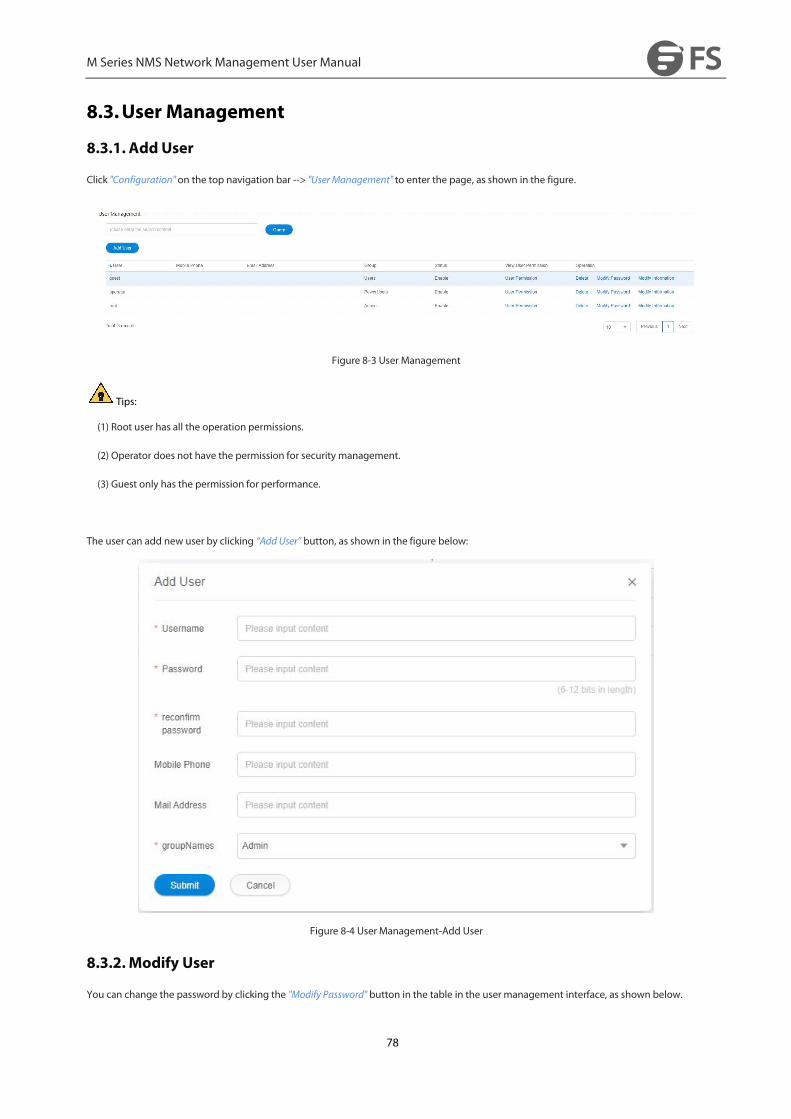
M Series NMS Network Management User Manual
78
8.3.User Management
8.3.1. Add User
Click "Configuration" on the top navigation bar --> "User Management" to enter the page, as shown in the figure.
Figure 8-3 User Management
Tips:
(1) Root user has all the operation permissions.
(2) Operator does not have the permission for security management.
(3) Guest only has the permission for performance.
The user can add new user by clicking “Add User” button, as shown in the figure below:
Figure 8-4 User Management-Add User
8.3.2.Modify User
You can change the password by clicking the "Modify Password" button in the table in the user management interface, as shown below.
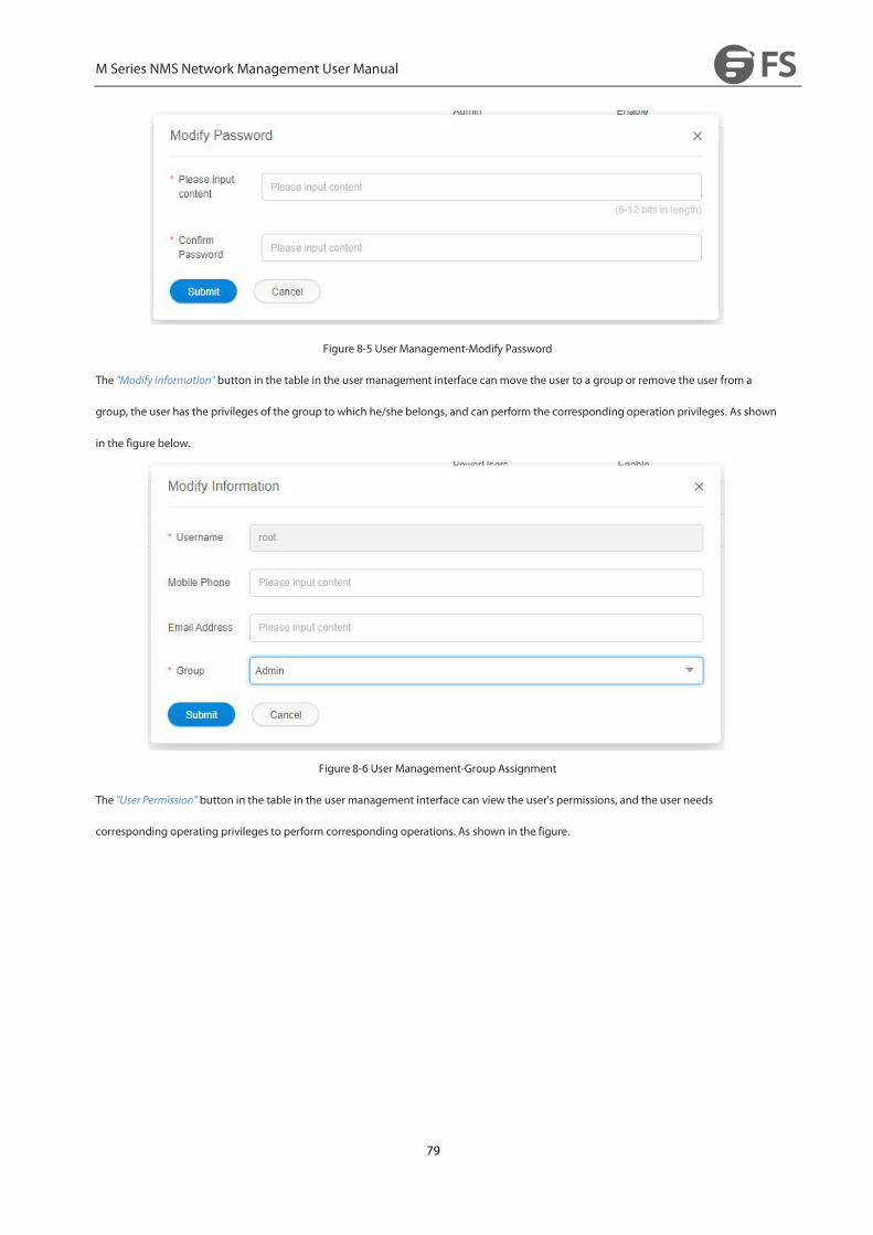
M Series NMS Network Management User Manual
79
Figure 8-5 User Management-Modify Password
The "Modify Information" button in the table in the user management interface can move the user to a group or remove the user from a
group, the user has the privileges of the group to which he/she belongs, and can perform the corresponding operation privileges. As shown
in the figure below.
Figure 8-6 User Management-Group Assignment
The "User Permission" button in the table in the user management interface can view the user's permissions, and the user needs
corresponding operating privileges to perform corresponding operations. As shown in the figure.

M Series NMS Network Management User Manual
80
Figure 8-7 User Management-User Right
8.3.3. Delete User
The "Delete" button on the table in the user management interface can delete the corresponding data, and the deletion operation will
confirm if the data is to be deleted or not, as shown below.
Figure 8-8 User Management-Delete User

M Series NMS Network Management User Manual
81
9.Routine Maintenance
9.1. Maintenance Requirements
9.1.1. Duties of Maintenance Personnel
Do daily and periodical maintenance according to the requirements of maintenance regulations and make corresponding records.
When there is a sudden accident, please follow the requirements of the maintenance regulations and report it to the competent
department or the supervisor immediately. If necessary, please request the other departments immediately to configure to eliminate
the faults in the shortest time. Meanwhile, record the major failure process and related data and archive them regularly.
Do not change the NMS configuration data at will. Do not change the machine disk or software at will. Whenever operations such as
change of disk and software or change of configuration data are performed, please make a record for maintenance and use in the
future.
9.1.2. Requirements for theMaintenance Personnel
In addition to doing the routine maintenance work carefully, finding out the hidden troubles in time and eliminating the hidden troubles
and faults, the maintenance personnel should also analyze, quickly locate and solve the problems that have occurred. Therefore, there are
high requirements for the maintenance personnel’s professional skills, operation standards and psychological qualities.
Familiar with NMS operations
Familiar with the networking of the system
Familiar with all kinds of alarms and performances of SDH system and correctly understand the meaning
Usually, the NMS system can send alarm before the user. If the user’s complaints precedes the NMS system, it should be timely
reflected to relevant units or departments after fault handling, so as to improve network management function and improve network
monitoring capability.
The processing principle: When each station receives the alarm or other abnormal situation, the station should contact and confirm it
with the Bureau. The fault point should be judged and located by using the NMS system or the monitoring terminal, and the failures
should be dealt with timely.
It is strictly prohibited to displace the disk at will, operate at will and break the fiber at will. Do not do other operations that
have nothing to dowith the troubleshooting!
When major circuit interruption occurs, departments at all levels should immediately organize rush repairs.
9.2.Routine Maintenance Items
Routine maintenance is the maintenance items that must be carried out every day. Through routine maintenance, we can grasp the
operation of the NMS system in time, find problems and solve problems in time, so as to maintain and remove hidden dangers in time. As a

M Series NMS Network Management User Manual
82
result, we can make the NMS system run reliably. In daily routine maintenance, we need to record the problems and failures in detail, and
provide reliable basis for analyzing the problems.
Table 9-1 Daily Routine Maintenance Items
Maintenance Items Requirements
Login the NMS Systemwith Low Level
User Identity
It should be able to log in normally. The operation permissions are not changed.
Ping NE Ensure that there is communication between NE and NMS.
Check Board StateCheck the state of every board, and ensure that every board is in its position. Check the state of
non-single board and ensure that the check state is successful.
Check AlarmEnsure that it can normally obtain or view the current or history alarm of every board. The
ineffective alarm should be shielded in time.
Check Performance Ensure that the performance data of every board can be obtained or viewed.
Check Information RecordOpen “Log Management” window in the NMS Status bar, the log information of the system can
be seen.
Instant Data BackupData backup should be carried out in time before change the configuration, so as to avoid loss of
important data caused by misoperation.
9.2.1. Login the NMS Systemwith Low Level User Identity
Because advanced users have all the permissions, if they login the NMS system, oncemisoperation is performed, it will cause serious
consequences. Therefore, unless necessary, it is recommended not to log in as an advanced user. A low level user (Users) should be created
to login the NMS system to perform daily operation.
Log in as an advanced user, then select "Configuration"--->"User Management" and select "Add User" button to pop up the "Add User" dialog
box, as shown in the figure below: Enter user name, email address, password and user level (i.e. group name) and click "Add".

M Series NMS Network Management User Manual
83
Figure 9-1 Add User—Assign Permissions
Then log off the login interface, and log in again with the identity of the newly added user. In daily operation, it is recommended that users
log in with this user identity.
9.2.2. Ping NE
In NMS server, click“CMD”→ “Command Prompt”, then you can ping the IP address of NE. If the text below is shown, it indicates that NE is
successfully ping, that is, there is communication between NMS and NE. In the same way, Ping the remaining NE to ensure that there is
communication between NMS and all devices.
Figure 9-1 Ping NE

M Series NMS Network Management User Manual
84
9.2.3. Check Board State
Check the status of every single board every day, there should be no alarm that the single board is not in place. In the "Global View" of the
browser, select the frame of the device you want to view, you can see the status of the single board.
Figure 9-2 NE Single Board State
9.2.4. Check Alarm
M Series provides a perfect alarm management function. In the routine maintenance, the network management personnel should check the
alarm information of all network elements every day, so as to find out the hidden troubles in time and prevent them in the bud.
Report Alarms
Click the current network element and select "Server Configuration"-->"SNMP Trap Configuration" to check if there is a trap address on the
same network segment as the managed server. If no configuration, please add the trap address in time to avoid the network element alarm
cannot be reported in time. Click the "Add" button to add the trap address, the default trap port is 16222.
Figure 9-3 Trap Report Alarm
Set Alarm Sound
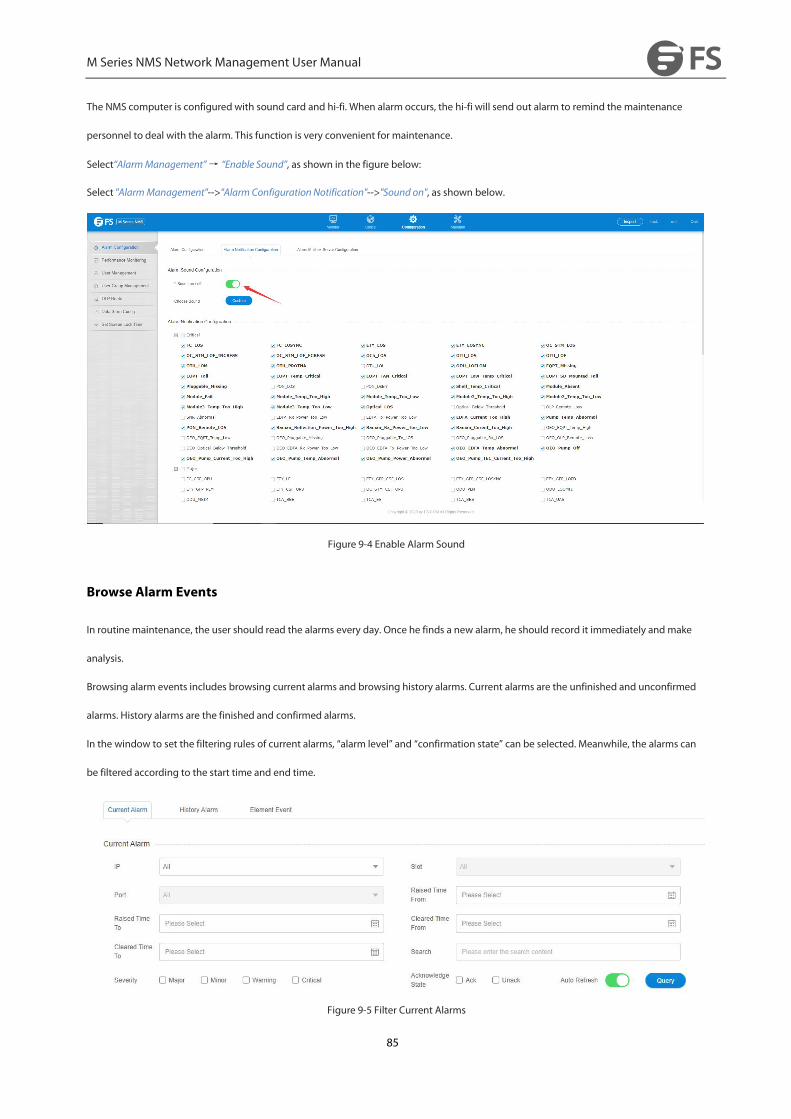
M Series NMS Network Management User Manual
85
The NMS computer is configured with sound card and hi-fi. When alarm occurs, the hi-fi will send out alarm to remind the maintenance
personnel to deal with the alarm. This function is very convenient for maintenance.
Select“AlarmManagement”→ “Enable Sound”, as shown in the figure below:
Select "AlarmManagement"-->"Alarm Configuration Notification"-->"Sound on", as shown below.
Figure 9-4 Enable Alarm Sound
Browse Alarm Events
In routine maintenance, the user should read the alarms every day. Once he finds a new alarm, he should record it immediately and make
analysis.
Browsing alarm events includes browsing current alarms and browsing history alarms. Current alarms are the unfinished and unconfirmed
alarms. History alarms are the finished and confirmed alarms.
In the window to set the filtering rules of current alarms, “alarm level” and “confirmation state” can be selected. Meanwhile, the alarms can
be filtered according to the start time and end time.
Figure 9-5 Filter Current Alarms

M Series NMS Network Management User Manual
86
9.2.5. Check Performance
If you want to check the performance, you need to configure performance statistics first. Then you can check the current performance. In
the performance statistics, performance events such as background error code block (BBE), bit error seconds (ES), serious bit error seconds
(SES) and unavailable seconds (UAS) are very important. They need to be checked very carefully. When the system is in normal operation,
these performance events should be 0 or very few (Performance values such as optical power cannot be 0). If a large number of
performance data is found, it indicates that the transmission signal quality of the system has deteriorated and there are potential failures. At
this time, you should not take lightly. The hidden dangers must be identified, so as to avoid major accidents such as business interruption.
Figure 9-6 View Current Performance Statistics
9.2.6. QueryMessage Record
Operations in the NMS system by all the users who login to the NMS system and some cases of the NMS system (e.g. the system startup and
exit, the user’s login and logout, illegal login, change of the continuous relationship between NMS and NE etc.) will be recorded by the NMS
system. Users need to check them regularly, so as to ensure the safety of the NMS system.
Select“LogManagement” to check the log state.

M Series NMS Network Management User Manual
87
Figure 9-7 Log Query
9.2.7. Instant Data Backup
In routine maintenance, data backup should be done before modifying the configuration, so as to avoid loss of important data caused by
misoperation. If the configuration is not modified, then data backup is not necessary.
Select“SystemManagement”→ “UploadNE Configuration” to upload all the configurations of NE to the NMS server.
Select "NE Configuration"-->"NE ConfigurationManagement" to upload all the configuration of the element to the network management
server.
Figure 9-8 Upload NE Configuration
9.2.8. Use One-Click Inspection
Use the one-click inspection function to export the information of all network elements on the network management to PDF files, so that it
is easy to view the basic information, optical power, alarms and other related information of all network element devices, and it is
convenient to check the abnormal status devices. (Refer to Section 4.6.11)

M Series NMS Network Management User Manual
88
9.3.Monthly Routine Maintenance
Table 9-2 Items of Monthly Routine Maintenance
Maintenance Items Requirements
Data Backup Make data backup to avoid loss of important data caused bymis-operation.
Performance Acquisition Check whether the NE performance acquisition is correctly set.
History Alarm & Performance Backup The history alarm and performance data needs to be backed up and archived.
Check the Connection of the
Database
Close M Series interface and then log back to M Series to check whether the connection of the
database is normal.
9.3.1. Data Backup
NMS Data Backup
Data backup needs to be performed in routine maintenance, so as to avoid loss of important data caused by misoperation. The prerequisite
is to shut down the NMS server first, and click to open “DB Tool”, then backup all the NMS configurations to the NMS server.
Figure 9-9 DB Tool

M Series NMS Network Management User Manual
89
Figure 9-10 NMS Data Backup
NE Data Backup
Select "NE Configuration"-->"NE ConfigurationManagement" to upload all the configuration of the element to the network management
server.
Figure 9-11 Upload NE Configuration
9.3.2. Performance Acquisition
The NMS Systemwill only collect the history performance of network elements which set the performancemonitoring point and the
monitoring time. Other network elements will not be reported. Therefore, it needs to regularly check whether the performance monitoring
point and the monitoring time of the network elements are correctly set.
Select "Configuration"--->"PerformanceMonitoring", then the Performance Monitoring Point page will pop up as shown in the figure below.

M Series NMS Network Management User Manual
90
Figure 9-12 Performance Monitoring Point
Check whether all the ports which need to collect performance data enable the performance monitoring point.
9.3.3. Check HardwareWork State
Modem is with factory configuration. It must be special device for special use. It cannot be used for other purpose. It needs to
check whether other work state is normal.
Check whether the work state of mouse, keyboard, printer and display is normal.
9.3.4. History Alarm & Performance Backup
Select“AlarmManagement”→ “History Alarm”and select the history alarms which need to be exported, and then click“Export”button, the
history alarm data can be exported to the NMS server installation directory (D:\NMS\report_out\history_ Alarm).

M Series NMS Network Management User Manual
91
Figure 9-13 Export History Alarm Data
Select "Maintain"-->"Performance History Info", click the "Export" button to export the historical performance statistics to the custom directory
of the network management server.
Figure 9-14 Export History Performance Statistics Data
9.3.5. Check Connection of Database
Close M Series interface and then log back to NMS system to check whether the connection of the database is normal.
No illegal shutdown of the NMS system!
9.4.Quarterly Routine Maintenance
Table 9-3 Quarterly Routine Maintenance Items
Maintenance Items Requirements
Proofread NMS Time Check the NMS clock and proofread it with the standard time.
Regularly change the login username
Login with a new user name and make detailed record of the user name and password.
Check Remote Login The device providers can login to the local host from the far end by dial-up.
Check NMS FunctionCheck whether NE and boards can be clicked. If there is equipped with the sound card, check
whether the sound of alarms can be normally got.

M Series NMS Network Management User Manual
92
9.4.1. Proofread NMS Time
Check the NMS clock and proofread it with the standard time. The purpose of this operation is to make the time of the NMS computer
consistent with the actual time, otherwise it will lead to start time and end time errors of the alarms and performances displayed in the NMS,
and will further cause misjudgment.
9.4.2. Regularly Change Login User Name
In order to improve the security of the system, the NMS login name and password need to be periodically changed.
Select "UserManagement" menu, change the login user password, change the new password, click "Submit
", the network management systemwill automatically exit, the user uses a new user name or password to log in.
Figure 9-15 Change User Password
9.4.3. Check Remote Login
Remote login plays an important role in quickly locating the fault. Therefore, it needs to check the remote maintenance function regularly.
Meanwhile, every maintenance personnel in the machine room should be familiar with the operation of remote maintenance. As long as
the NMS computer is with remote maintenance function, it needs to be checked regularly.
Please contact our technician to make functional test at the far end. If the maintenance personnel of the machine room are familiar with this
operation, the remote maintenance function can be checked by another computer. That’s no problem if remote login to NE is available.
9.4.4. Check NMS Function
Whether the alarm and performance can be obtained; whether the new alarm can be refreshed automatically; whether the network
element and board can be clicked; if the sound card is installed, whether each alarm sound can be obtained normally; whether the state of
the single board is normal. These maintenance items are also routine maintenance items, please refer to the first three sections of this
chapter; Routine Maintenance Items for more details.
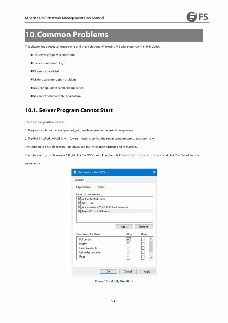
M Series NMS Network Management User Manual
93
10.Common ProblemsThis chapter introduces some problems and their solutions while using M Series system. It mainly includes:
The server program cannot start.
The account cannot log in.
NE cannot be added.
NE time synchronization problem.
NMS configuration cannot be uploaded.
NE cannot automatically report alarm.
10.1. Server Program Cannot Start
There are two possible reasons:
1. The program is not installed properly, or there is an error in the installation process.
2. The disk installed by NMS is with low permissions, so that the server program cannot start normally.
The solution to possible reason 1: Re-download the installation package and re-install it.
The solution to possible reason 2: Right click the NMS root folder, then click“Properties”→ “Safety”→ “Users”, and click “Edit” to add all the
permissions.
Figure 10-1 Modify User Right
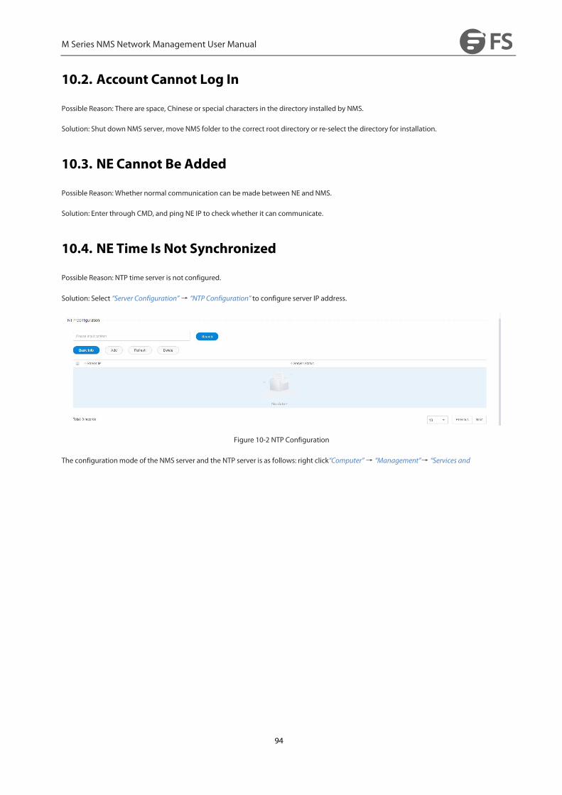
M Series NMS Network Management User Manual
94
10.2. Account Cannot Log In
Possible Reason: There are space, Chinese or special characters in the directory installed by NMS.
Solution: Shut down NMS server, move NMS folder to the correct root directory or re-select the directory for installation.
10.3. NE Cannot Be Added
Possible Reason: Whether normal communication can bemade between NE and NMS.
Solution: Enter through CMD, and ping NE IP to check whether it can communicate.
10.4. NE Time Is Not Synchronized
Possible Reason: NTP time server is not configured.
Solution: Select “Server Configuration”→ “NTP Configuration” to configure server IP address.
Figure 10-2 NTP Configuration
The configurationmode of the NMS server and the NTP server is as follows: right click“Computer”→ “Management”→ “Services and
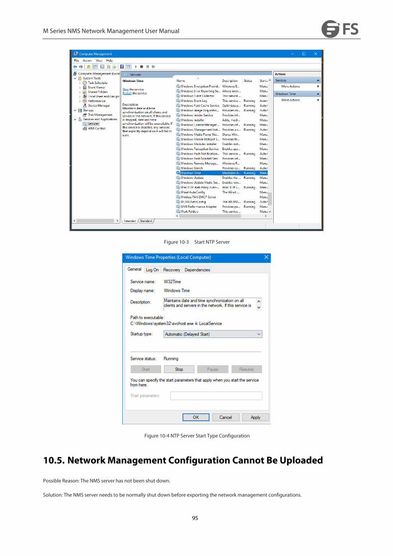
M Series NMS Network Management User Manual
95
Figure 10-3 Start NTP Server
Figure 10-4 NTP Server Start Type Configuration
10.5. NetworkManagement Configuration Cannot Be Uploaded
Possible Reason: The NMS server has not been shut down.
Solution: The NMS server needs to be normally shut down before exporting the network management configurations.
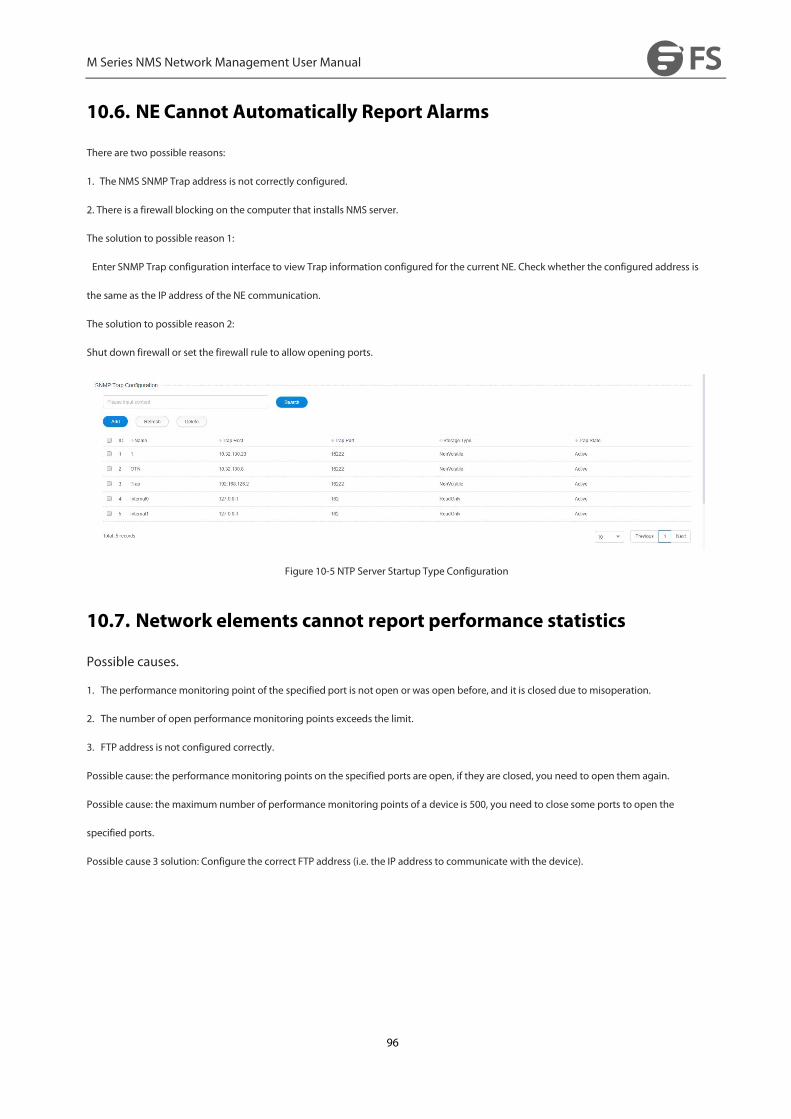
M Series NMS Network Management User Manual
96
10.6. NE Cannot Automatically Report Alarms
There are two possible reasons:
1. The NMS SNMP Trap address is not correctly configured.
2. There is a firewall blocking on the computer that installs NMS server.
The solution to possible reason 1:
Enter SNMP Trap configuration interface to view Trap information configured for the current NE. Check whether the configured address is
the same as the IP address of the NE communication.
The solution to possible reason 2:
Shut down firewall or set the firewall rule to allow opening ports.
Figure 10-5 NTP Server Startup Type Configuration
10.7. Network elements cannot report performance statistics
Possible causes.
1. The performancemonitoring point of the specified port is not open or was open before, and it is closed due to misoperation.
2. The number of open performancemonitoring points exceeds the limit.
3. FTP address is not configured correctly.
Possible cause: the performancemonitoring points on the specified ports are open, if they are closed, you need to open them again.
Possible cause: the maximum number of performancemonitoring points of a device is 500, you need to close some ports to open the
specified ports.
Possible cause 3 solution: Configure the correct FTP address (i.e. the IP address to communicate with the device).
M Series NMS Network Management User Manual
97
10.8. After changing the IP address of the server PC, the running
server cannot login or shuts down automatically.
Possible Reason: When the NMS software is running on the back end of the network management server, modifying the IP address of the
server will cause the NMS application on the back end of the network management server to fail to take effect on the newly modified IP
address or cause the NMS application on the back end of the network management server to shut down automatically, as the network
management client browser cannot log in (display user name and password error) to the network management server.
Solution: After changing the IP address of the managed server, you need to manually close the NMS application on the managed server, and
then you need to manually restart the NMS application to make the newly modified IP address take effect on the NMS application.
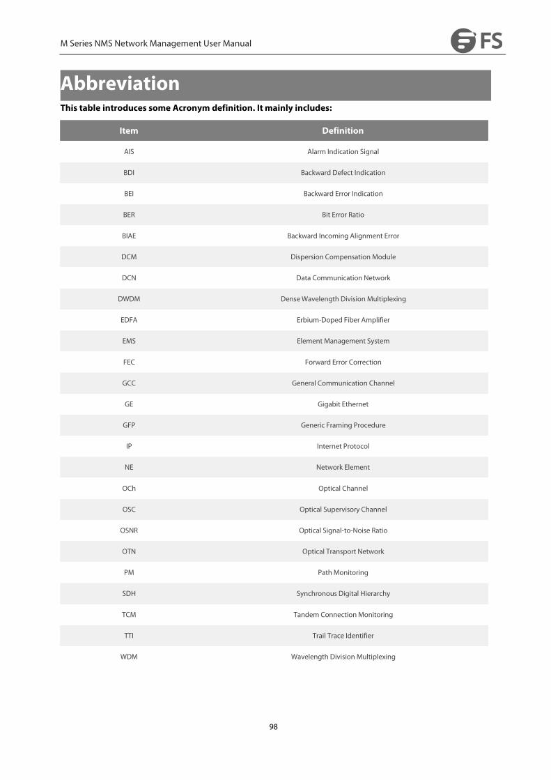
M Series NMS Network Management User Manual
98
AbbreviationThis table introduces some Acronym definition. It mainly includes:
Item Definition
AIS Alarm Indication Signal
BDI Backward Defect Indication
BEI Backward Error Indication
BER Bit Error Ratio
BIAE Backward Incoming Alignment Error
DCM Dispersion Compensation Module
DCN Data Communication Network
DWDM DenseWavelength Division Multiplexing
EDFA Erbium-Doped Fiber Amplifier
EMS Element Management System
FEC Forward Error Correction
GCC General Communication Channel
GE Gigabit Ethernet
GFP Generic Framing Procedure
IP Internet Protocol
NE Network Element
OCh Optical Channel
OSC Optical Supervisory Channel
OSNR Optical Signal-to-Noise Ratio
OTN Optical Transport Network
PM PathMonitoring
SDH Synchronous Digital Hierarchy
TCM Tandem ConnectionMonitoring
TTI Trail Trace Identifier
WDM Wavelength Division Multiplexing


