
MantelMountTM1A Installation Instructions
Thank you for choosing the MantelMount television wall mount. Please read this entire manual before you begin. Do not unpack contents of
this package until you verify all of the requirements on PAGE 4.
www.MantelMount.com
Do not let children operate, pull on, or hang from MantelMount. Do not let children push MantelMount upward to the top position - this will cause the mount to slam against the wall due to the upward force of the springs. Only a person tall enough to control the mount all the way to the top should operate MantelMount.
This product contains small parts that can be a choking hazard. Do not let children play with any of these small parts! Keep children away from the work area during installation.
! CAUTION:
Do not use this product in any way, or for any purpose, that is not specifically described in these instructions. MantelMount is not responsible for damage or injury caused by incorrect installation or improper use.
! CAUTION:
This product is intended to be installed by professional installation contractors, or persons familiar with the tools and methods required for this installation. If you are not sure about your ability to perform this installation, you must contact a professional. MantelMount is not responsible for damage or injury caused by incorrect installation or improper use.
! CAUTION:
! WARNING!
MantelMount TM1A PAGE 1
IMPORTANT SAFETY INSTRUCTIONS - SAVE THESE INSTRUCTIONS
TM
PAGE 2 MantelMount TM1A
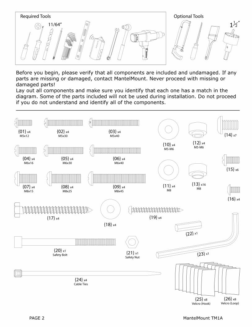
Required Tools Optional Tools1
21 “11/64”
{02} x4M5x30
{01} x4M5x12
{10} x4M5-M6
{11} x4M8
{12} x4M5-M6
{14} x7
{15} x6
{16} x4
{13} x16M8
{03} x4M5x40
{05} x4M6x30
{04} x4M6x16
{06} x4M6x40
{08} x4M8x25
{07} x4M8x15
{09} x4M8x45
{18} x4
{17} x4 {19} x4
{20} x1Safety Bolt {21} x1
Safety Nut
{22} x1
{23} x1
{25} x8Velcro (Hook)
{26} x8Velcro (Loop)
{24} x4Cable Ties
Before you begin, please verify that all components are included and undamaged. If any parts are missing or damaged, contact MantelMount. Never proceed with missing or damaged parts!Lay out all components and make sure you identify that each one has a match in the diagram. Some of the parts included will not be used during installation. Do not proceed if you do not understand and identify all of the components.
MantelMount TM1A PAGE 3
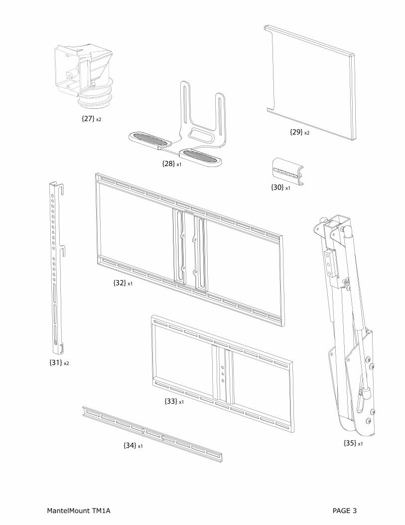
{27} x2
{28} x1
{29} x2
{30} x1
{31} x2
{34} x1
{32} x1
{33} x1
{35} x1

MantelMount is designed for use only with decorative fireplaces that are not the primary heat source for a house. Temperature at the front edge of mantle should never exceed 110° F.
A B
C
E
DMantle must not extend from mounting surface more than 14 inches.
The space above the mantle must be taller than the TV. The required space depends on how far out the mantle extends. Refer to chart below and add this additional height to TV height to determine if space is tall enough.
Wall must be WOOD STUD FRAME only. There must be at least 2 studs available for mounting. Wall covering must not exceed 5/8 inches thick.
TV weight must be between 40 - 100 pounds and have a screen size larger than 47 diagonal inches. Consult TV Owner’s Manual for verification.
Please verify that your installation meets all of these CRITICAL requirements:
110°FMAX.
14 inches MAXIMUM
2 STUDS
If mantle extends:
Less than 8 inches
8 - 10 inches
10 - 12 inches
12 - 14 inches
This is required space height:
TV height plus 2 inches
TV height plus 4 inches
TV height plus 5 inches
TV height plus 7 inches
WEIGHT:40 - 100 POUNDSTV h
eight
Mantle Extends:
Spac
e hei
ght
PAGE 4 MantelMount TM1A
larger than 47”

1 Use Vertical Brace {31} to determine if television is a flat back or an irregular back. An irregular back will require spacers and longer screws to fill the space between the Vertical Brace and the TV.
Choose the correct screw diameter and length for the TV. Hand-thread screw combination into the TV to ensure there is adequate thread engagement without hitting the bottom of threaded insert. Use only minimum amount of spacers (if required).
2
3 Possible Screw Combinations shown with maximum spacer usage (if spacers are required). Note: The sleeve on the Spacer always faces the Screw.
Mount Vertical Braces {31} making sure the bottom of the Brace is LESS THAN ONE INCH ABOVE the bottom of television.
4
Flat Back Irregular Back Irregular Back(Recessed Threads)
Spacers
Must leave a gap in threaded TV insert
7-10 threads minimum
engagement
! CAUTION:Do Not use screws that are too long for the threaded inserts of Television. This can damage internal components.
One inch (25mm) MAXIMUM
MantelMount TM1A PAGE 5
{02}
{01}{10}
{10}
{10}
{10}
{11}
{11}
{11}
{12}
{12}
{10}{12}
{10}{12}
{13}
{13}{13}
{13} {13}
{13} {13}
{13}
{13}
{03}
{05}
{04}
{06}
{08}
{07}
{09}

Determine Vertical Position of Wall Plate: The image at right shows that the further out a mantle extends, it can interfere with the arc of the lowering TV. MantelMount must be installed a minimum distance above the mantle, based on the same dimensions from “Requirement E”. See the chart below for the height required above the mantle. This dimension will be used in Installation Step 9.
NOTE: If the available wall space above mantle is close to the required space in the table from “Requirement E” (due to the ceiling, for example) then it is important to use the exact dimensions from this chart. However, if the available wall space above mantle is much taller than required, then these heights are only minimum requirements.
Determine Horizontal Position of Wall Plate: Occasionally a television will have an unbalanced “Center of Gravity”, meaning it is heavier on one side than the other. This can cause the television to lean to one side when hanging on a mount. To correct this, the television must be moved sideways slightly on Mantel-Mount until it balances horizontally. However, this causes the television to be off-center from the mantle. By measuring this unbalance before installation, the Wall Plate {32} can be installed off-center by the same distance and the same direction to compensate.
Example: If the true center-of-gravity is 1 inch to the left of the front TV centerline, then MantelMount should be installed 1 inch to the left of the mantle centerline.
To determine if TV is unbalanced, temporarily mount Horizontal Bar {34} as shown using 2 screws {15}. Use this bar as a handle and lift TV from the center. If TV is balanced, there is no need for compensation. If the TV leans to one side, move your point of lifting off-center and measure the distance required to obtain balance. This distance will be used in step 11 to install Wall Plate {32} off-center by the same amount.
If you are unable to perform this step, you can proceed with installation, and if you discover an unbalance when you hang the TV, you can remove the TV and re-position the Wall Plate {32} to compensate.
When you are finished with this step, remove Horizon-tal Bar {34} and the 2 screws {15} for use later.
6
5
CL
USE THIS INFORMATION FOR INSTALLATION STEP 11:
If mantle extends:
Less than 8 inches
8 - 10 inches
10 - 12 inches
12 - 14 inches
Required installation height:
2 inches above mantle
4 inches above mantle
5 inches above mantle
7 inches above mantle
USE THIS CHART FOR INSTALLATION STEP 9:
PAGE 6 MantelMount TM1A

Minimum Height from STEP 5
Measure the centerline of the mantle. Mark with tape on the wall.7
Align the arrows on the Wall Plate {32} pointing upward. Center and level the plate above mantle and position the height using the table in STEP 5. Mark the 4 spots for lag bolts directly on center of studs.
9
Locate at least two studs with a stud finder. Locate the center of these studs by using a sharp awl or finish nail poked through the drywall to locate each edge. Lag bolts must be installed into the CENTER of the studs.
8
Pre drill the 4 holes with 11/64” drill bit to a depth of 2.5 inches (65mm) including wall covering. Note: Wall covering (drywall) must not exceed 5/8” thickness.
10
CLCutout shown for reference
MantelMount TM1A PAGE 7

11 Adjust Wall Plate {32} horizontally, using the results of STEP 6, to compensate for an unbalanced television center-of-gravity, up to a maximum of 2 inches left or right. Move Wall Plate in the SAME DIRECTION as the offset from STEP 6.Loosely install Lag Bolts {17} and Washers {18}.
12 ! CAUTION:Do Not overtighten Lag Bolts {17}. Tighten only until the washers are firmly against the wall plate. Damage due to overtightening can cause property damage or injury.
Insert top tab of Lifting Mechanism {35} into the slot of Wall Plate {32} then slide bottom into position.13 Align all four holes and install Screws {14}. Tighten with
the supplied Wrench {23}.14
1
2
2 Inches MAX
2 Inches MAX
PAGE 8 MantelMount TM1A
DO NOT damage or scratch
the rods of the Gas Springs!

MantelMount TM1A PAGE 9
OPTIONAL Signal Cable Routing Boxes {27}: If Signal Cables have already been routed to television location, please skip ahead to step 21. Also, if the mounting wall is an external wall, or if there is no hollow area behind mantle, please skip ahead to step 21.
The next several steps are for the use of optional Routing Boxes {27} included with MantelMount. These boxes allow signal cables (not power cables) to be run inside hidden metal conduit through the framed area enclosing the fireplace, in order to rout signal cables to a side wall. See the image below for a typical installation. Any installation must comply with all local building codes.
These boxes require the purchase of metal conduit, (2 inch I/D.), long enough for the desired location. When purchasing conduit, use the Routing Box to verify size, but do not screw it in very far because it can be difficult to remove. Conduit can be twisted or “unwound” slightly to help position or remove the Routing Box during test-fit or installation. Both ends of the conduit must be cut cleanly with a hacksaw before inserting the Routing Boxes.
! WARNINGYou must verify with local building codes the minimum distance that the conduit must be located away from the fireplace components. See the image below. Failure to obey local building codes can result in property damage and even loss of life.
! WARNINGRouting Boxes {27} are for signal cables only. Running power cables next to signal cables can cause signal noise that can affect audio and video performance. Also, your local building codes might not allow power cables to be run through conduit. Failure to obey local building codes can result in property damage and even loss of life.
Parts not included:
Wall platewith large hole
2“ I.D. metal conduit
Minimum Distance
Routing Box {27}
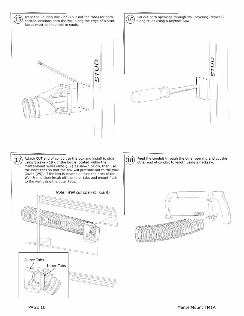
Trace the Routing Box {27} (but not the tabs) for both desired locations onto the wall along the edge of a stud. Boxes must be mounted to studs.
Attach CUT end of conduit to the box and install to stud using Screws {19}. If the box is located within the MantelMount Wall Frame {32} as shown below, then use the inner tabs so that the box will protrude out to the Wall Cover {29}. If the box is located outside the area of the Wall Frame then break off the inner tabs and mount flush to the wall using the outer tabs.
Feed the conduit through the other opening and cut the other end of conduit to length using a hacksaw.
15 Cut out both openings through wall covering (drywall) along studs using a Keyhole Saw.16
17 18
STU
D
STU
D
Note: Wall cut open for clarity
Outer Tabs
Inner Tabs
PAGE 10 MantelMount TM1A
MantelMount TM1A PAGE 11
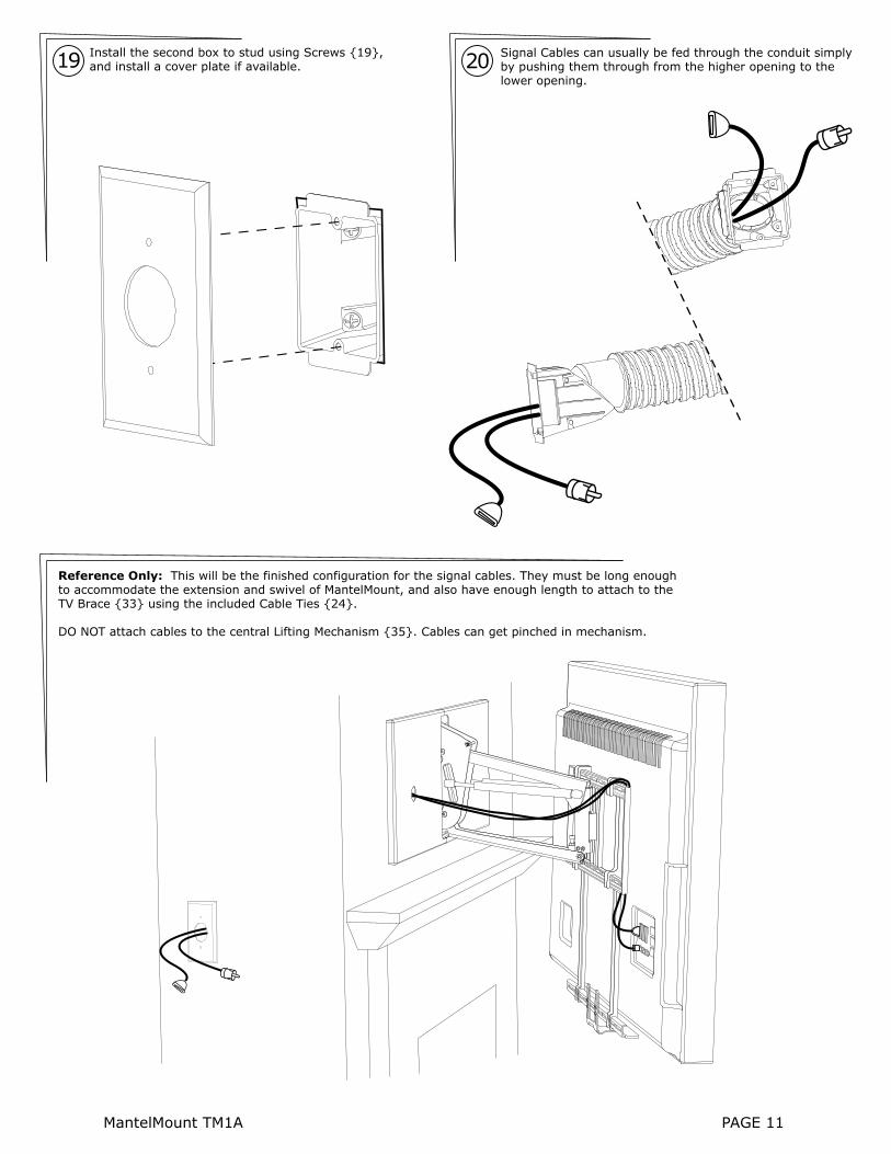
19 Install the second box to stud using Screws {19}, and install a cover plate if available.
Signal Cables can usually be fed through the conduit simply by pushing them through from the higher opening to the lower opening.
20
Reference Only: This will be the finished configuration for the signal cables. They must be long enough to accommodate the extension and swivel of MantelMount, and also have enough length to attach to the TV Brace {33} using the included Cable Ties {24}.
DO NOT attach cables to the central Lifting Mechanism {35}. Cables can get pinched in mechanism.

IN
Marked “IN”
Install the TV Brace {33} to the Lifting Mechanism {35} while ensuring that the side marked “IN” is facing the Lifting Mechanism.
21 Level the TV Brace and tighten the 3 screws {14} using the supplied wrench {23}.22
23
Pull down the TV Brace until the upper arm is below the Safety Hole. DO NOT HIT MANTLE! Second person inserts Safety Bolt {20} and installs the Safety Nut {21}. Slowly release the TV Brace. Lifting Mechanism should be held at horizontal position.
24 ! WARNING:Do Not put hands into Lifting Mechanism without the Safety Bolt and Safety Nut installed. The power of the Lifting Mechanism can cause bodily injury!
THIS STEP REQUIRES TWO PEOPLE
MantelMount TM1A PAGE 12

25
Carefully hang Television onto the TV Brace making sure that all four hooks on the Vertical Braces {31} engage the TV Brace.
DO NOT allow the Television to drop far enough to cause the Lifting Mechanism {35} to hit the mantle.
MantelMount comes pre-adjusted to reduce the possibility of contacting the mantle, but you should always be prepared to remove the television at this stage to make the proper correction.
THIS STEP REQUIRES TWO PEOPLE
26 If the Lifting Mechanism {35} appears to be too close to the mantle, remove television. Go to STEP 31 and make an adjustment to the Bottom Stop position. Repeat this process until the Lifting Mechanism is a safe distance from the mantle when the TV is in place.
Check TV with a Level. Carefully slide the TV sideways, if required, until it is balanced and horizontal, up to a MAXIMUM OF 2 INCHES left or right. This distance should match the compensation distance used in STEP 11.If you did not make any compensation in STEP 11, but now you find that you need to, you should remove TV and repeat STEP 11 using this distance, but instead you must slide the Wall Plate {32} in the OPPOSITE direction than the direction you slid the TV for this step.
27
PAGE 13 MantelMount TM1A
CL
2 inches
MAX
2 inches
MAX

MantelMount TM1A PAGE 14
28 Install 4 Screws {15} through the TV Brace {33} and into the Vertical Braces {31}.
Install the Horizontal Bar {34} with Screws {15}. The Horizontal Bar MUST BE aligned with the end of TV Brace {33} or the Lifting Mechanism will not work properly.
29
Align
1 inch MAX (25mm)
30 Install the Handle {28} with Screws {16} into the Horizontal Bar. Handle MUST be within one inch (1”) of the bottom of the Television frame so that it does not hit the mantle.Firmly Insert the Rubber Bumper {30} into the center slot of the Horizontal Bar {34}.

Adjusting for Bottom Stop Position: Loosen the Locknut and adjust the Bottom Stop screw to the desired stopping position. Turning the screw clockwise will raise the Bottom Stop position, and turning the screw counter-clockwise will lower the TV closer to the mantle when the TV is in the lowered position.
Tighten the locknut after adjustments are made.
Adjusting for Television weight: With Safety Bolt {20} in place, use the included Hex Tool {22} with a socket wrench to adjust the long bolt inside the Lifting Mechanism {35}. Turning this bolt increases or decreases the lifting force of the mechanism. Turn the bolt clockwise to increase the force for heavy TVs, or turn counter-clockwise for lighter TVs. This adjustment can take several turns.
Adjust the bolt until the TV gently stays in the lowered position. Move the TV up and down within the range below the Safety Bolt. The TV should almost stay up against the Safety Bolt, but should slowly lower to the Bottom Stop.
32
31
Adjusting for Bottom Stop and Television Weight:
A
Locknut
AdjustmentScrew
Safety Bolt {20} Safety Nut {21}
PAGE 15 MantelMount TM1A
B
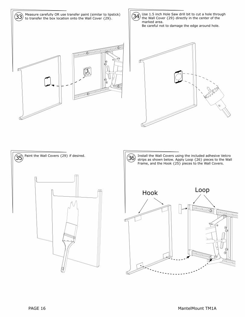
35 Paint the Wall Covers {29} if desired. Install the Wall Covers using the included adhesive Velcro strips as shown below. Apply Loop {26} pieces to the Wall Frame, and the Hook {25} pieces to the Wall Covers.
36
PAGE 16 MantelMount TM1A
Measure carefully OR use transfer paint (similar to lipstick) to transfer the box location onto the Wall Cover {29}. 33 34 Use 1.5 inch Hole Saw drill bit to cut a hole through
the Wall Cover {29} directly in the center of the marked area. Be careful not to damage the edge around hole.
LoopHook

With the television in the lowered position, remove the Safety Nut {21} and Safety Bolt {20} from the Lifting Mechanism {35}.
KEEP THIS BOLT AND NUT in a safe place for use in the future. They are needed to remove the television or change the Gas Springs. Recommendation: Tape them to the inside of the Wall Cover {29}.
37
MantelMount TM1A PAGE 17
Never swing the television until it hits the mantle on either side.
! CAUTION:
Never release the handle before it is fully upright. MantelMount is strongest in the top position, and allowing it to slam closed can damage televisions. Always control the lifting process.
! CAUTION: Never allow children to play around or operate MantelMount. Property damage or personal injury can occur.
! CAUTION:

10
34
11
29
28
12
23
24
9
23
8
13
1816
15
6
26
19
20
2717
4
5
33
2416
14
252021
23
2118
7
3
2
30
1
22
32
31
15
58
59
35 36 37
38 39 40
4144
4546
47
50
51 52
53 54
5556
57
49
4842 43
2416
14
INSTR
UCTIO
N MAN
UAL
Additio
nal
Inst
alla
tion P
arts
PAGE 18 MantelMount TM1A

MantelMount TM1A PAGE 19
ITEM
NO
.PA
RT N
UM
BER
DES
CRIP
TIO
NQ
TY.
QTY
.
112
010
1
212
015
1
312
050
1
412
028
1
512
032
1
612
020
1
712
055
1
812
065
1
912
025
1
1012
038
2
1112
042
1
1212
035
1
1312
078
1
1412
076
2
1512
074
2
1612
115
10
1712
070
1
1812
150
4
1912
165
1
2012
186
2
2112
164
2
2212
184
4
2312
176
Wal
l Fra
me
Wal
l Bra
cket
Adj
ustm
ent B
lock
Upp
er A
rm
Low
er A
rm
Pivo
t Bra
cket
Slid
ing
Bloc
k
Pivo
t Blo
ck
TV F
ram
e
TV V
ertic
al B
race
TV H
oriz
onta
l Bra
ce
Cent
er H
andl
e
Shaf
t 74m
m
Shaf
t 57m
m
Shaf
t 45m
m
Bush
ing
Dep
th B
lock
Ball
Post
with
Loc
k W
ashe
r
Rubb
er B
umpe
r M8
Lock
nut
M8
Was
her
Flat
Scr
ew M
6 x
16
Roun
d H
ead
Scre
w M
8 x
16
Roun
d H
ead
Scre
w M
8 x
16 w
/ Was
her
9
24 2512
170
1
1218
26
Cap
Scre
w M
8 x
130
3012
125
2
3112
130
2
3212
128
2
3312
160
2
3412
178
35 36 37 38 39 40 41 42 43 4544 46 47 48 49 50
6
1218
94
1219
04
1219
14
1219
3
1219
4
4
2612
172
1
2712
174
4
Cap
Scre
w M
8 x
50
Cap
Scre
w M
6 x
10
2812
180
4
2912
120
2
Roun
d H
ead
Scre
w M
5 x
8
Han
dle
Grip
Wal
l Cov
er
Elec
tric
al B
ox
Elec
tric
al S
wiv
el
Gas
Spr
ing
Roun
d H
ead
Scre
w M
6 x
10
M5
x 12
M5
x 30
M5
x 40
M6
x 16
M6
x 30
4
1219
74
1219
84
1219
94
1216
64
1216
74
1211
64
1211
816
1215
44
1215
7
1219
5
44
1215
5
M8
x 15
M8
x 25
M8
x 45
Was
her
M6
Was
her
M8
Spac
er M
6
Spac
er M
8
Lag
Bolt
60m
m
Woo
d Sc
rew
50m
m
M6
x 40
Was
her,
Lag
Bolt
4
51 52 53 54
1215
11
1218
51
1220
21
1220
3
M6
x 80
Cap
Scr
ew
Lock
nut M
6
Alle
n W
renc
h M
6
Hex
Too
l M8
1
55 56
1213
98
1214
1
Velc
ro S
trip
HO
OK
Velc
ro S
trip
LO
OP
8
5712
162
Tie
Wra
p4
59TM
1AIn
stru
ctio
n M
anua
l1
5812
135
Rubb
er B
umpe
r1
ITEM
NO
.PA
RT N
UM
BER
DES
CRIP
TIO
N

PAGE 20 MantleMount TM1A
www.MantelMount.com
115º Vertical Rotation
40º Horizontal
Rotation
Temperature-Sensitive Handles: Change to red color at temperatures above 110ºF to warn users that the
fireplace is too hot for TV safety
Auto-Straightening: Flattens the TV as it is raised
to the upper position to prevent rotation into the wall
Wall Covers:Can be painted to match wall and conceal the mount frame
Extends outward up to 15 inches, bringing the
action right into the room!
Horizontal Adapter:Adapts MantelMount to solid horizontal surfaces with full
functionality. Sold Separately.


