
DEPARTEMENT DE PHYSIQUEDE L’ECOLE NORMALE SUPERIEURE
LABORATOIRE KASTLER BROSSEL
Manual for the computer control ofLITHIUM
by Florian Schreck7.8.2001

Contents
1 Basic hardware knowledge 1
1.1 Cards in the computer . . . . . . . . . . . . . . . . . . . . . . . 1
1.2 The principle of the bussystem Multiout . . . . . . . . . . . . . 2
2 Lowlevel structures 3
2.1 IO units . . . . . . . . . . . . . . . . . . . . . . . . . . . . . . . . 3
2.2 Capsulated IO . . . . . . . . . . . . . . . . . . . . . . . . . . . . 4
2.3 Renaming of ports . . . . . . . . . . . . . . . . . . . . . . . . . . 5
2.4 IEEE communication . . . . . . . . . . . . . . . . . . . . . . . . 6
2.5 Serial communication . . . . . . . . . . . . . . . . . . . . . . . . 6
2.6 Timing . . . . . . . . . . . . . . . . . . . . . . . . . . . . . . . . . 8
2.7 The idea behind Portlist . . . . . . . . . . . . . . . . . . . . . . 9
2.8 The idea behind Sequence . . . . . . . . . . . . . . . . . . . . . 9
2.9 Principle of an experimental run . . . . . . . . . . . . . . . . . 11
2.10 The RF sweeps . . . . . . . . . . . . . . . . . . . . . . . . . . . . 12
2.11 Debugging . . . . . . . . . . . . . . . . . . . . . . . . . . . . . . . 13
3 Mediumlevel structures 14
3.1 The use of the Menu System . . . . . . . . . . . . . . . . . . . . 14
3.2 The parameter administration . . . . . . . . . . . . . . . . . . . 16
3.2.1 Utilities for parameter administration . . . . . . . . . . 18
4 Highlevel structures 20
4.1 The principle of an experimental serie . . . . . . . . . . . . . . 20
i

4.2 The principle of a measurement queue . . . . . . . . . . . . . . 21
4.3 Some special functions of the program . . . . . . . . . . . . . . 21
4.4 Last words . . . . . . . . . . . . . . . . . . . . . . . . . . . . . . . 21
5 Basic modifications of the program 23
5.1 Adding a shutter . . . . . . . . . . . . . . . . . . . . . . . . . . . 23
5.2 Adding a box to multiout . . . . . . . . . . . . . . . . . . . . . . 23
5.3 Adding a new Block in the experimental sequence . . . . . . . 23
A The units of LITHIUM 24
ii
Chapter 1
Basic hardware knowledge
1.1 Cards in the computer
Four cards take over special functions in the computer
• DAS1601
This card contains the 100kHz timer chip used for the timing of the
experimental sequence (a standard Intel clock chip, as also used for
the internal clock of the computer). It contains a digital I/O chip with
24bit (also standard intel, as the one for the parallel port). Four digi-
tal inputs, two analog outputs and six analog inputs. The 24bit digital
output is used for the bus system, one analog input for the Fluores-
cence measurement, one digital input for the Water and Temperature
Error signal. The card is connected to a output box, made by our
electronicians. If another analog input has to be used, a OP driver has
to be put into this box, the driver that are in place are too weak.
• DDA08
This card contains another 24bit of digital outputs and 6 analog out-
puts. If the DAS1601 breaks, the bus can be hooked up here, only
the adresses in Multiout.pas have to be changed. These outputs are
thought as spare outputs in case no output is left on the bus and there
is no time to installe a new output box. But you should better use the
bus system.
• IEEE card
1
This is for communication with IEEE gear, like synthesizers, . Useful
tools came with this card and are in c : \debug488\ .
• serial card
Two serial ports for the communication with the Nd:YAG and the data
aquisition computer. Another two ports can easily be added by adding
another card (already tried), but pay attention to the interrupts and
IO adresses.
1.2 The principle of the bussystem Multiout
The bus system (Multiout) has a 16 bit data bus, 6bit adress bus and a 1bit
subbusselection and a 1bit strobe bit. The bus is hooked on a driver box,
splitting it up on two cables (the subbusses). At the moment always both
subbusses are activated and it is rather stupid to sparate them, I would
change the electronics of the driver box to use the subbusadressbit as a
normal adress bit. Boxes with analog or digital outputs are hooked on the
bus. Each box is optoisolated. Each 16bit latch or 16bit DA converter has
its own adress, decoded by a 8bit comparator. Most of the boxes decode
8adress bits (one of them is strobe) the oldest boxes only five, they have
to be modified if new boxes are hooked up since the 32 5bit adresses are
used up. The modification is very simple and consist of wirering the 3
highest bits from the output of the optocouplers to the input of the adress
decoder. The adress is coded by hooking the 8bits of the second input of
the comparator to GND or 5Volts. Pay attention, the bits are rather mixed
up (21436587 in stead of 12345678). Some of the boxes have an activated
error input. The outputs can only be programmed if a 5V signal enters
there. If it goes to GND the outputs go to GND too. The digital output
box for the IGBTs and the Cameras is split in two, 8bits are secured, 8bits
not. This is to prevent that all IGBTs go off at the same time which can
provoque overtension.
2
Chapter 2
Lowlevel structures
Now I will describe the ideas behind LITHIUM and the relationships be-
tween the different units.
2.1 IO units
Four units, for DAS1601, DDA06, Multiout and the printer port LPT speak
with the in/out ports, each contains an initialisation routine and input
output routines, see exapmle.
unit DAS1601;
unit DDA06;
unit Multiout;
unit LPT;
PROCEDURE DAS1601Init;
procedure DAS1601analogOut(Channel: byte; Value: word );
{channel:0..1; value:0..4095}
Function DAS1601analogIn(channel:byte):word;
{channel:0..7;value:0..4095}
Procedure DAS1601digitalOut(channel:byte;Value:byte);
{channel:0..3} Function DAS1601digitalIn(bitNR:byte):boolean;
{bitNr: 0..3} Function DAS1601FastanalogIn:word;
In addition these units contain code necessary for the DEBUG option,
writing all the IO trafic to a file on the harddisk if necessary. A speciality
3

of MULTIOUT.PAS is that here the channel numbers are translated to the
physical adresses, using these tables (look them up in MULTIOUT.PAS for
completeness :
{0, 1, 2}
Const DigAdr:array[0..NumbDig-1] of byte=(29,30,31);
AnaAdr:array[0..NumbAna-1] of byte=(20,21,22,23,24,25,...
{0, 1, 2, 3, 4, 5,...
The numbers in { } give the adresses from the program calling MUL-
TIOUT.PAS point of view, the numbers in ( ) give the physical adress.
If a new box is added these tables have to be extended. (First increase
NumbDig or NumbAna, then add unique adresses. Each analog box has
four DACs and so four adresses.)
2.2 Capsulated IO
From the programmers point of few, it would be nice to have one adressspace
for all cards, so he does not allways have to think to which card exactly he
has to write when a bit is set. That’s one of the functions of IO.PAS. The
other is that several write commands going to the same digital 16bit port,
but to different bits can be accumulated. The commands are only stored
in a buffer containing the value of the port it should have. Only when
a IOUpdate command is found, IO searches through its list of ports and
writes the ports which were changed. This increases speed and makes it
possibe to change several bits on one port exactly at the same moment.
That’s used for the switchoff of the Magnetic trap and the triggering of
the camera system for example. A WAIT command always calls IOUpdate
before waiting. The table linking the virtual adress space to the boxes adress
space (for Multiout that’s NOT the physical adress space, see before) has
the following structure (given is only the digital ports table, the analog
ports one is more or less the same, see IO.PAS):
const DigBuf:array[0..MaxDigOut-1] of TDigBuf=(
(card:CMultiOut;channel:0;NrBits:16;value:0;update:true), {channel 0}
(card:CMultiOut;channel:1;NrBits:16;value:0;update:true), {channel 1}
4

(card:CMultiOut;channel:2;NrBits:16;value:0;update:true), {channel 2}
(card:CDDA06 ;channel:0;NrBits:8;value:0;update:true), {channel 3}
(card:CDDA06 ;channel:1;NrBits:8;value:0;update:true), {channel 4}
(card:CDDA06 ;channel:2;NrBits:8;value:0;update:true), {channel 5}
(card:CDAS1601 ;channel:3;NrBits:4;value:0;update:true), {channel 6}
(card:CLPT ;channel:1;NrBits:8;value:0;update:true) {channel 7}
);
On the righthandside the adresses from the rest of the programs point
of view are given. Left the outputsystem and the channel of this system
is given. Space is reserved for the buffer and a statusflag is set. NrBits
contains how many bits a channel has. This table has also to be extended
if a new box is added. The rest of the program (which means EXPIO.PAS)
speaks with the ports only through IO.PAS. In addition IO.PAS contains
some code neccessary for a correct handling of Portlists (see there), storing
and recalling the buffers.
2.3 Renaming of ports
It is incomprehensible if in the final experimental sequences code the adresses
of special bits appear. If for convenience an other outputbit should be used
for a function, the whole code would have to be searched for the usage of
that bit. That’s why every port gets its own name describing as clearly
as possible its function, also if the name gets very long (copy paste helps).
Here is an example:
procedure ShutterProbe(onoff:boolean);
begin
if SequenceOut then IOdigitalOut(1,9,not onoff)
else SequenceBooleanArg(ShutterProbe,onoff,0);
end;
A call of ShutterProbe calls bit 9 of address 1 (pay attention, bits here
are numbered from 0..15, on the boxes they are numbered from 1..16.) The
experimental sequence is executed twice for each experimental run. The
first time to gather general information (like total time consumption), then
5
for real. Thats why the outputs are blocked if SequenceOut is false. In fact
then the command itself is stored in a list in memory and is called when this
list is worked through. The list itself serves to deplace the actual output
routine from their place when it is called during the sequence (eg. give the
command to a shutter earlier). See Sequence.pas for more info.
Other things done by ExpIO.pas are implementing simple IEEE com-
mands, organising the execution of WAIT commands for Portlist and Se-
quence (see there).
2.4 IEEE communication
The unit IEEE contains routines for this. Each IEEE machine has its own
supplementary unit, like NDYAG.PAS, SIGGEN.PAS, PULSGEN.PAS hid-
ing the IEEE commands behind nice names. SIGGEN.PAS is a bit special
because it implements an abstract synthesizer which is mapped to the ac-
tually used one, so that one synthesizer can be exchanged with another
just by changing the type in the list of synthesizers in SIGGEN.PAS. The
supported types are: SRS, Marconi, Rhode&Schwartz and the old Synthe-
sizer from Grynbergs lab. The GPIB addresses of Synthesizers are given in
SIGGEN.PAS, all the others in EXPIO.PAS.
2.5 Serial communication
Two units are at disposition for serial communications: serial1.pas and
serial2.pas. One uses DOS interrupts and is slow, but works. The other
speaks directly to the chip is fast, but when I tried it, there where many
missing characters after transmission. So an error correction protocol would
have to be implemented to use this unit. Now the simple DOS unit is used
for NDYAG.PAS and VISION.PAS. NDYAG.PAS implements all possible
commands for the NDYAG. The COM port used has to be set before calling
this unit using NdYAGSetComPort(COMx) (x=1,2). This is done during
the initialisation in EXP.PAS.
The communication with Vision is done through VISION.PAS. The com
port is set there. If new parameters which Vision has to know before the
image is taken, like camera parameters, have to be transmitted this unit
6

has to be modified. But pay attention, if the communication grows longer,
the VisionWaitingTimes have to be increased in the configuration menu.
The main commands in VISION.PAS are
procedure VisionSetCameraParameters(...
function VisionCameraReady(Camera:byte):boolean;
function VisionStartSerie(...
function VisionStopSerie:boolean;
function VisionTakeAbsorptionPicture(...
procedure VisionSendPictureData(
procedure VisionMessage(Message:string);
The communication goes as follows. First the Camera is initialised with
SetCameraParamaters. When CameraReady responds with true, eventu-
ally a Serie is started. The experimental sequence is executed a first time
to determine the total time. This together with some other parameters
is sent with VisionTakeAbsorptionPicture. The returned ] READY* puts
both computers in synchronisation. Fine tuning is done with the Andor-
TriggerCalibrationAbsorption and AndorTriggerCalibrationAbsorption pa-
rameters accesible in the Andor menu. For the Matrox camera this is not
necessary. 100ms before the image is taken, Vision puts the Andor sys-
tem in the external triggerable mode. In this mode the CCD isn’t cleaned
well any more, that’s why it’s invoked as late as possible and that’s why
the total time has to be known before the experimental sequence starts.
VISION and LITHIUM synchronise each other with some Cameratriggers
and ] READY* signals sent back to take the three images (or one if the
noise images comes from harddisk). After finishing of the image taking and
digitising VisionSendPictureData sends supplementary information and Pa-
rameters modified since the last image. With VisionMessage messages can
be sent to Vision which are shown in Visions statusline and in the statusline
of all Lifeconnected computers. This serves to see at a glance where in a
sequence the experiment is, when sitting in the office and to see if a Tem-
perature or water error did appear. Some additional commands can guide
vision to do any of the commands also available in Visions Menus.
7

2.6 Timing
TIMING.PAS implements a good delay routine using the DAS1601 Counter
0. If the DAS1601 card isn’t detected the PC internal timer is used. The
timer is a 16bit timer counting at a 100kHz rate. Initially upon call of
StartCounter, its value is set to $FFFF and also stored as last value in
the OldCounter variable. Then it starts to count down. When a WAIT
command is met, first IOUpdate is invoked to write all outputs. This and
all the operations since the last WAIT command take an unknown amount
of time. Now the new value expected for the counter at the end of the wait
is determined by substracting the number of counter cycles corresponding
to the waitingtime from OldCounter. If the counter is already below this
value, the program took too long. Synchronisation is no longer guaranteed
and an error printed on the screen, indicating the identity of the too short
wait. This musn’t be catastrophic, in most cases the sequence is still fine,
but a bit longer. If the counter is higher, TIMING waits till it reaches the
value calculated, stores this value in OldCounter and gives control back to
the calling routine. Like this some IO operations can be added without
influencing the timing at all, the sequence becomes completely repeatable
(at a timescale of 10µs). The most difficult thing to take into account
has been the timeroverflow appearing each 500ms. This means that a Wait
command has to appear at least every 500ms. (This can be circumvented by
calling CheckCounter from time to time, which calculated the time elapsed
since the last wait and stores the actual countervalue. This is taken into
account when the next wait appears.)
You have to remember to call startCounter shortly (less than the first
wait-time and less than half a second) before the first Wait command. This
is necessary if Waits are used out the experimental sequence, like in the
menu. To identify Wait commands in the sequence to each delay time a
femtosecond delay is added which of course doesn’t play a role. But the
amount of femtoseconds identifies the wait. Example:
WAIT(100+ID*42);
The function GetTimeSinceLastWait:double; is used when fine synchro-
nising the two computers and gives in that case the time needed by the
Vision system to get into the gears.
8
2.7 The idea behind Portlist
Sometimes commands to the ports have to be emmitted in a very fast
sequence. When using the normal way of writing using IO.PAS and af-
terwards IOUpdate, about 70µs of administration overhead are spent each
IOUpdate. When using a Portlist, the commands are not executed at once.
Rather the values really written to the IO ports of the computer and the
Waits between them are stored in a list. During the creation of this list
the administration time is spent. Next the list is put to the ports without
”thinking”. In the following an example taken from MAGTRAP.PAS, the
capture in the Ioffe trap:
SequenceStartistDuringWait(159*ID+2);
SwitchMOTDecharging(off);
IOUpdate;
SetMOTVoltage(PinchCapacitorVoltageStart);
SetMOTCurrent(MaxMOTCurrent);
Wait(160*ID+PinchCapacitorChargingTime);
SwitchIGBT(1,off);
SwitchIGBT(2,off);
SwitchIGBT(3,off);
SwitchIGBT(4,on);
.
.
.
SequenceStopPortList;
Its the 159ms wait, that is used to do all the administrative work. After
its done the rest of the 159ms is waited and then the Portlist is executed.
Why the commands are preceeded by ”Sequence” is explained in the next
section. This is not necessary under all conditions.
2.8 The idea behind Sequence
The initial idea behind sequence was the following. A shutter has to be
opened. But when at the point in the sequence when you need it to open,
9
it’s too late to give the command since the shutter has a delay. You have to
write to the output port BEFORE the command appears in the sequence.
This is possible when first storing the whole experimental sequence in mem-
ory. If a command appears that has to be executed earlier, its position in
the list is just changed. This works, but there are many problems in the
details. The memory of our computer is not sufficient to store every single
command. So you can regroup commands in subroutines and only store the
call to this subroutine. This is essential when doing ramps of currents or
radiofrequencies, when thousands of commands are executed. Inside these
blocks regrouping is of course impossible. If a command appears just after
a block which should be preexecuted just a few milliseconds before, thats
not possible. Thus a sufficiently long security wait should be put in place
before any command using pretiming is used. Next, to make work portlist
and pretiming work together was a big effort. In fact in daily life its so in-
convenient to use pretiming that I’ve abandoned it. The problem is before
all that it’s extremly difficult to debug an experimental sequence when the
commands can hop around.
But sequencing has another advantage. That’s that the experimental
sequence is executed twice. Like that one can collect global parameters
of the sequence like the ”life of the atoms” (a descriptive string marking
with two characters each step taken by the atoms) or the total time. These
parameters can be transferred to VISION before experiment is started. For
the total time that’s necessary. Of course these informations can also be
obtained without storage of the commands in memory. So in principle one
could modify the program in a way that the whole experimental sequence is
stored as one block. This will help if one day the memory becomes short. An
other point where the preexecution is used is the programming of the puls
generator. Its programmed during the preexecution and its different setups
(up to 12) are stored in its memory. During the experimental sequence these
settings are just recalled, which is much faster.
Now some examples of the use of the sequencing commands:
procedure ShutterProbe(onoff:boolean); begin
if SequenceOut then IOdigitalOut(1,9,not onoff)
else SequenceBooleanArg(ShutterProbe,onoff,0);
end;
10
The command SequenceBooleanArg stores ShutterProbe on the heap, to-
gether with its argument onoff. The delay is 0 and would be negative for
a preexecution and positive for a later execution than the place at which
ShutterProbe is encountered in the Sequence. The procedure ShutterProbe
has to be called ”far”, which is automatically the case when it is declared
in the interface of a unit like EXPIO.PAS. In other cases the far modi-
fier has to be put after the declaration of the procedure. Since PASCAL
can’t analyse at runtime the arguments of a procedure to which it gets a
pointer reference, different storage commands had to be implemented for
each possible argument list (see SEQUENCE.PAS).
2.9 Principle of an experimental run
Now let’s take a look at an experimental run, paying attention how Sequence
is used. I think the code should by now be self explaining. You can find it in
EXP.PAS, it the routine TakeAbsPicture. Probably its a good exercise to go
through this routine and the whole experimental sequence to understand
how it is programmed by using all the lower level structures described
before. That’s how the experiment is programmed in the daily life. By
looking how things are made, copying and modifying them you should be
able to do most of the things necessary for the future of the experiment.
StartCounter;
ReInitialiseSystem;
StartSequenceDuringWait(62*ID+334);
SynchronizeToLine; syncs whole sequence to line trigger
do stuff which will be stored on heap
for example the whole experimental sequence
if DoTransferQuadrupoleExpansion
then TransferQuadrupoleExpansion; just a example
cut trap for TOF
PictureWait:=GetTotalWait; get time of the sequence till picture
trigger camera
PauseSequence;
things are executed at once now.
Check Fluorescence
11

UnPauseSequence;
StartCounter;
VisionTakeAbsorptionPicture(PictureWait-AndorTriggerDelay-
GetTimeSinceLastWait-AndorTriggerCalibrationAbsorption,
Atompath,...
StopSequence; and off it goes! the stored sequence is executed
Cleanup: ramp down power supplies, sent additional parameters to
Vision VisionSendPictureData(...
And this is how a sequence block is implemented. There are lots of
them in MAGTRAP.PAS. Ramp(command, StartValue, EndValue, Time,
CommandTime) is a very useful command to do ramps. The command
is executed repeatedly with arguments going linearly from StartValue to
EndValue. The whole ramp takes Time. Every CommandTime, command
is called. CommandTime is typically 0.2, but can be larger if command
regroups several commands writing on the ports. AtomPath is the string
describing the sequence.
procedure TransferQuadrupolExpansion;far;
begin
FinalTrap:=’transfered MagTrap with Quadrupol Expansion’;
AtomPath:=AtomPath+’Qe’;
SequenceStartBlockNoArg(TransferQuadrupolExpansion);
Ramp(SetTransferCurrentControlVoltage,TransferCurrentEnd,
TransferQuadrupolEndCurrent,
TransferQuadrupolExpansionTime,0.2);
SequenceEndBlock;
end;
2.10 The RF sweeps
The unit RFSWEEP.PAS contains a class describing RF sweeps. It contains
methods to save and load a sweep, to display it graphically, to create a Menu
to modify it by hand and to send it to the Synthesizers.
12
2.11 Debugging
To debug the experimental sequence, all operations occuring during the
sequence can be written to a protocol file. There are different modi for this.
One creates a table that can be displayed with Origin, giving a multichannel
oscilloscopes view of the experiment. Another gives a ASCII list of all
output operations. DEBUG.PAS contains some Basic FileI/O functions
for this. The routines really writing in the file are in the DDA08.PAS,
Multiout.pas, the SERIAL.PAS and the IEEE.PAS units.
13

Chapter 3
Mediumlevel structures
Now we come to the structures concerning not the experimental sequence
but the user interface and the parameter administration.
3.1 The use of the Menu System
MENU.PAS contains procedures to declare either a Menu, giving the option
to start subroutins, which can also describe submenues, giving so rise to a
menu structure, or Dialogs, which are used to modify the experimental
parameters. When the user is doing nothing IdleProc is called which is
mapped to an Idle routine in EXP.PAS showing the clock, beeping at 7:50
pm for the pot des eleves, closing the atomic beam shutter if the experiment
is not used for quite a while, showing the error status and starting the
screensaver. I won’t explain MENU.PAS. Its application becomes clear
from looking at our menustructure implemented in MENUSYS.PAS. Here
an example for a Menu, calling utilities from EXP.PAS. If this menu calls an
equal procedure describing another menu the user get the impression of a
menu structure. The Menus which have to be adapted when the experiment
grows are the manual operation menus. Here actions are executed when
a button is pressed. Don’t forget StartCounter at the beginning of such a
small experimental sequence if WAITs are used and an IOUpdate at the
end.
procedure MenuUtils1;
var MenuInfo : pMenuInfo;
14
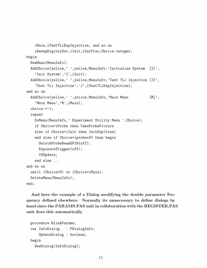
iMain,iTest7LiExpInjection, and so on
iSweepDigitalOut,iInit,iCalFluo,Choice:integer;
begin
NewMenu(MenuInfo);
AddChoice(yellow,’ ’,yellow,MenuInfo,’Initialise System [I]’,
’Init System’,’I’,iInit);
AddChoice(yellow,’ ’,yellow,MenuInfo,’Test 7Li Injection [J]’,
’Test 7Li Injection’,’J’,iTest7LiExpInjection);
and so on
AddChoice(yellow,’ ’,yellow,MenuInfo,’Main Menu [M]’,
’Main Menu’,’M’,iMain);
choice:=-1;
repeat
DoMenu(MenuInfo,’ Experiment Utility Menu ’,Choice);
if Choice=iProbe then TakeProbePicture
else if Choice=iInit then InitExp(true)
end else if Choice=iprobeoff then begin
SwitchProbeBeamGPIB(off);
ExposureTrigger(off);
IOUpdate;
end else ...
and so on
until (Choice=0) or (Choice=iMain);
DeleteMenu(MenuInfo);
end;
And here the example of a Dialog modifying the double parameter Fre-
quency defined elsewhere. Normally its unnecessary to define dialogs by
hand since the PARAMS.PAS unit in collaboration with the REGISTER.PAS
unit does this automatically.
procedure BlinkParams;
var InfoDialog : PDialogInfo;
UpdateDialog : boolean;
begin
NewDialog(InfoDialog);
15

AddT(yellow,InfoDialog,’Blink Parameters’);
AddR(yellow,InfoDialog,Frequency,’Frequency [Hz]’,
’Frequency’,0,10000,1);
BackupVars(InfoDialog);
DoDialog(InfoDialog,’Blink Parameters’,UpdateDialog);
end;
3.2 The parameter administration
An experimental sequence is controlled by a lot of parameters (at the
moment about 700). All these parameters are loaded from disk when
LITHIUM is started, stored to disk when it is quit or a serie of experi-
mental runs is started. They are also sent to Vision and stored with each
image. (In fact only the first time when Vision is started ALL the param-
eters are sent. Afterwards only the modified ones are sent, to gain time.)
Clearly a system is necessary to handle all these parameters. The necessary
routines for this system are in REGISTER.PAS (helped by STRING.PAS).
Besides doing the things described before, the necessary Menuentries and
Dialogwindows are automatically created. The actual declaration of the pa-
rameters takes place in the unit PARAMS.PAS. Each parameter has to be
declared once in the interface part of the unit. Next it has to be registered
in the implementation part. Here is an example:
unit params.pas
interface
const MaxCompressIoffeTrap=17;
var DoCompressIoffeTrap:array[1..MaxCompressIoffeTrap] of boolean;
CompressIoffeTrapTime:array [1..MaxCompressIoffeTrap] of double;
BarCurrentIoffeTrap:array [1..MaxCompressIoffeTrap] of double;
implementation
uses Register;
procedure RegisterParameters;
16

begin
some code here
DummyReg:=new(PRegistry,init(@Registry,Registry,true,
’Doppler cooling Parameters’,Dummy));
RegisterBoolean(MarkColor,@DoCompressIoffeTrap[1], True ,
’C1DoCompressIoffeTrap’,’Do Compress Ioffe Trap 1 ? [Yes/No]’);
RegisterDouble (StdtColor,@CompressIoffeTrapTime[1],0,0,50000,
’C1CompressIoffeTrapTime’,’Compress Ioffe Trap Time 1 [ms]’);
RegisterDouble (StdtColor,@BarCurrentIoffeTrap[1],
0 ,0,1000 , ’C1BarCurrentIoffeTrap’,
’Bar current in compressed Ioffe Trap 1 [0..1000 A]’);
some code here
end;
The first line in the RegisterParameters unit declares a new Parame-
ter submenu. Registry is a pointer to the list of parameterpages of type
PRegister. The boolean parameter tells REGISTER to show this parame-
ters in the menu with the title ’Doppler cooling Parameters’. Dummy is a
procedure without arguments, called whenever the corresponding parame-
termenu is quit. This is used for example on the MOT parameter page to
update the AOM frequencies when the MOT detunings were changed.
Next the command RegisterBoolean registers a boolean variable decid-
ing if the magnetic trap will be compressed. Since many deformations of
the magnetic trap appear in the sequence, this is in fact the first boolean
in an array of booleans declared in the implementation section. This is
a very typical manner to simplify the experimental sequence. The proce-
dure compressing the trap is called with a byte parameter, defining which
of the 17 compressions should be performed. It is also typical to call a
certain block of the experimental sequence in dependence of a DoItOrNot
boolean variable. Lets look in detail to the RegisterBoolean routine. The
first parameter is the color in which the dialogentry will appear. The color
MarkColor is reserved for parameters deciding about the fate atoms will
take. If a boolean parameter with MarkColor is switched on in a param-
etermenu, in the main menu a green spot will be displayed at the side of
the call to the parametersubmenu. This is very usefull to see at a glance
17
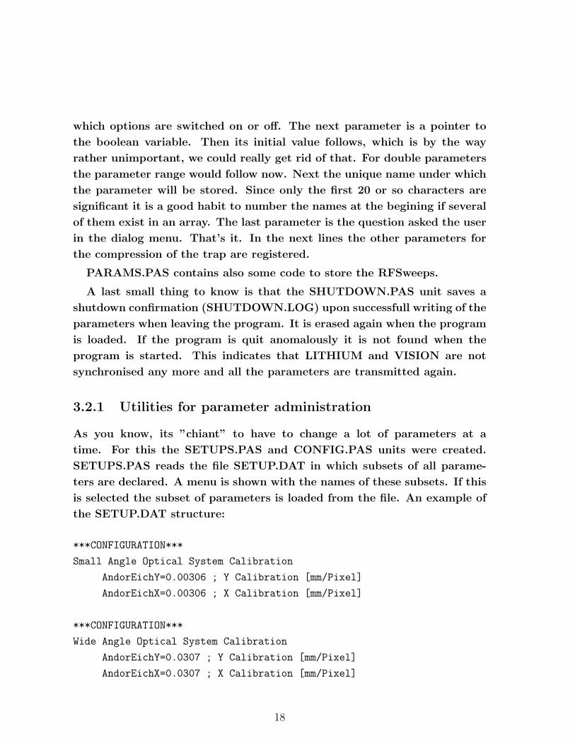
which options are switched on or off. The next parameter is a pointer to
the boolean variable. Then its initial value follows, which is by the way
rather unimportant, we could really get rid of that. For double parameters
the parameter range would follow now. Next the unique name under which
the parameter will be stored. Since only the first 20 or so characters are
significant it is a good habit to number the names at the begining if several
of them exist in an array. The last parameter is the question asked the user
in the dialog menu. That’s it. In the next lines the other parameters for
the compression of the trap are registered.
PARAMS.PAS contains also some code to store the RFSweeps.
A last small thing to know is that the SHUTDOWN.PAS unit saves a
shutdown confirmation (SHUTDOWN.LOG) upon successfull writing of the
parameters when leaving the program. It is erased again when the program
is loaded. If the program is quit anomalously it is not found when the
program is started. This indicates that LITHIUM and VISION are not
synchronised any more and all the parameters are transmitted again.
3.2.1 Utilities for parameter administration
As you know, its ”chiant” to have to change a lot of parameters at a
time. For this the SETUPS.PAS and CONFIG.PAS units were created.
SETUPS.PAS reads the file SETUP.DAT in which subsets of all parame-
ters are declared. A menu is shown with the names of these subsets. If this
is selected the subset of parameters is loaded from the file. An example of
the SETUP.DAT structure:
***CONFIGURATION***
Small Angle Optical System Calibration
AndorEichY=0.00306 ; Y Calibration [mm/Pixel]
AndorEichX=0.00306 ; X Calibration [mm/Pixel]
***CONFIGURATION***
Wide Angle Optical System Calibration
AndorEichY=0.0307 ; Y Calibration [mm/Pixel]
AndorEichX=0.0307 ; X Calibration [mm/Pixel]
18

***CONFIGURATION*** is a keyword, declaring a new subset. The
next line has to contain its name, then the parameterdeclarations follow.
The example shows the use of this to change the calibration quickly between
the two lens systems of the ANDOR camera.
The CONFIG.PAS utility stores and recalls all parameters. It resembles
the save and loadgame option of a video game. About 20 slots are open.
When selected in the savemenu, the user is asked to give the configuration a
name and then all parameters are stored in this slot. Physically this corre-
sponds to writing all setup files (RFSweep, Unimess and Parameters) into
a subdirectory named SLOTA to SLOTZ. In addition a info.dat file is saved
containing the name and creation date and time of the saved configuration.
The contents of all these files is loaded when the Configmenu is build up,
that’s why it takes a small amount of time. Loading works analogous.
19

Chapter 4
Highlevel structures
The last units not mentioned until now will be described here. Lets take
a top down look on the program. The main program is LITHIUM.PAS. It
calls InitExp from EXP.PAS and MainMenu from MENUSYS.PAS. The
experimental sequence is defined in EXP.PAS and MAGTRAP.PAS. In
EXP.PAS are many more features, like the screensaver, experiment ini-
tialisation, all the test functions for analog and digital outputs and the
serial ports test of laser injection, commands for the measurment queue,
Fluorescence oscilloscope...
4.1 The principle of an experimental serie
The next feature to be described are experimental series. The proce-
dures involved in this are declared in UNIMESS.PAS, EXP.PAS and MIX-
DATA.PAS. UNIMESS.PAS administrates all the data necessary to de-
scribe a serie. It makes the menus necessary to create one, stores and
loads their description in UNIMESS.DAT and finally calls DoUniMess in
EXP.PAS. An universal measurement consists of executing the same ex-
perimental sequence over and over again by linearily varying up to four
parameters. As you all use the program I won’t describe more what it
does. Since the measurements are executed with an arbitrary order, MIX-
DATA.PAS provides a way of doing this in a quasi-random way. If the serie
is stuck after having gone half through, it can be resumed, the starting point
has to be changed changing MeasurementStartPoint in the Configuration
parameters menu. Vision reorders the measurments again in the correct
20
order. A Vision command can be executed at the end of a Serie. By the
way, the BigMeasurement option is in the meanwhile disfunctional.
4.2 The principle of a measurement queue
A serie only varies some parameter linearly. A measurement Queue is
much more versatile. When creating a queue all parameters are stored on
harddisk. An entry in the queue can consist of a simple experimental run
or of a whole serie (not involving RF sweep parameters, which are treated a
bit apart from the other parameters). When programing a queue it is useful
to first test and then store the different parameter sets using the CONFIG
utility. Next the old Queue is erased and then one by one the configurations
recalled and stored with QueueAbsorptionImage. At the end the Queue can
be executed once, or in circle. This makes it possible to test the stability
of the system at two different places in the sequence. Or different Series
can be started automatically one after the other. Physically Queues are
stored in a special directory on the harddisk. Every element has its own
subdirectory. All parameters and a file MESS.DAT describing the element
are stored. It would be very easy to write an utility displaying the contents
of the queue and making giving the possibility to selectively delete elements
from the queue and not only to erase all.
4.3 Some special functions of the program
There are a lot of test functions for all kinds of in and outputs, the serial
port, the IEEE port and lot of more stuff defined in EXP.PAS and accessible
via the Utility menus. Just take a look and explore.
4.4 Last words
Some words to finish. Don’t try to keep in mind the position of every
routine in MAGTRAP.PAS or EXP.PAS. If you want to find something,
first look it up in the parameter Menu of the program. You will see the
name of the parameter used in Lithium in the status bar. Next search for
21
this parameter in EXP.PAS or MAGTRAP.PAS and you will find the point
where you want to modify the program.
The Turbo Pascal editor has many very usefull, but somewhat hidden
functions. You can find the in the Menu help-Contenst-editor. My favorite
are Ctrl K 1 and Ctrl Q 1 to store the place of the cursor and hop back
later (1 can be any number). Ctrl Y erases a whole line. Shift Cursor hops
the cursor from word to word.
22

Chapter 5
Basic modifications of the program
5.1 Adding a shutter
In EXPIO.PAS a new routine has to be declared, copy a old shutter routine.
Give it a new name. Don’t forget to modify the outpot port and to adapt
the name in the SequenceRegister command. Finally initialise the Output
in Init in EXP.PAS or in the case of a shutter in PrepareShutters. A Shutter
command has also to be copied to OpenShutters and CloseShutters. Finally
the element has to be reinitialised in the procedure ReInitialise after a
sequence.
5.2 Adding a box to multiout
Extend the tables in MUTIOUT.PAS and IO.PAS.
5.3 Adding a new Block in the experimental se-
quence
Look up the sections PARAMS.PAS and SEQUENCE.PAS in this manual.
23

Appendix A
The units of LITHIUM
program codetable;
Writes ASCII codes and characters on screen
unit config;
uses params,menu,dos,crt;
Stores and Loads configurations to slots. Configuration consists
of Parameters declared in Params.pas Creates Menus necessary for
these operations.
UNIT DAS1601;
Basic analog and digital In/Out routines for the DAS1601 card. Our
bus system is connected to this card. The DAS1601 Timer is used in
Timing.pas. The Fluorescence and Error signals are connected to
this card too.
unit DDA06;
uses Portlist;
Basic analog and digital In/Out routines for the DAS1601 card.
This is a spare card with 6 analog outputs and 24 digital outputs
independent of the Bus system. In case the DAS1601 card breaks,
the Bus can be hooked to these 24bits.
unit Debug;
24
Basic FileI/O functions for the debugging option. Debugging means
writing all experiment outputs also in a file. This emulates a
multi channel oscilloscope.
unit Exp;
uses unimess,IO,ExpIO,Params,Timing,Vision,MixData,DAS1601,
DDA06,MultiOut,Serial,IEEE,menu,menusys,MagTrap,Debug,
SigGen,Sequence,NdYAG;
This is the main program. It uses the different units to establish
the connection with Vision, prepare an experimental serie or a
simple experimental run. When the experimental sequence goes to
the magnetic trap, MagTrap.pas is called, simply to keep the
filesize of Exp.pas short. MagTrap.pas can be considered as part
of Exp.pas. There are also other functions here: The screensaver,
experiment initialisation, all the test functions for analog and
digital outputs and the serial ports test of laser injection,
commands for the measurment queue, Fluorescence oscilloscope,
measurement queue
unit ExpIO;
uses Params,crt,IO,IEEE,Timing,Sequence,PortList,debug,Pulsgen;
This unit is used to give names which are easy to memorize to the
different output and input ports. It also blocks the output if the
experimental sequence is executet in the preparation mode and
stores the command in the sequence list. It contains also simple
IEEE Commands and all but the synthesizers GPIB adresses. The
latter are in siggen.pas. It also reimplements some comands of
Sequence.pas and contains a general Wait command that is
reinpertreted in dependence of the actual execution state of the
experimental sequence (preparation, portlist, SequenceOut). This
is used also to calculate the total execution time.
unit HP8563A;
uses IEEE;
This unit isn’t used in Lithium but can be used to read traces
from the HP8563A READHP8563A is the mainprogram using this unit.
25

UNIT ieee;
uses debug;
This unit contains everything necessary to communicate using the
IEEE interface. The communication can be written in a protocol in
debug mode. Don’t forget about the very useful
c:\DEBUG488\DEBUG488 (and c:\DEBUG488\IEEE488) utility, which
monitors IEEE commands in real time, if you have trouble with
IEEE.
unit IO;
uses crt,DAS1601,DDA06,MultiOut,LPT;
This unit unites all Input and output operations The digital ports
are projected to virtual 16 Bit ports All channels are sorted and
get a unique channel number The number of IO operations is
minimized using buffers Data is written out when IOUpdate is
invoked or if IOdigital/analogIn/OutDirect is used. If the
calculation effort (30s per IOUpdate) is too long and slows down
the experiment, a Portlist has to be used. A Portlist is
constructed by executing the sequence without actualy writing to
the ports. All I/O operations and WAIT commands are stored in the
list. Then the list is written out "without thinking", which is
faster. The analog Values go from 0 to \$FFFF even for 12bit DACs.
Look up the tables in this unit to get the link between channel
numbers uses in expio.pas and channelnumbers used in the
individual output system driver units DAS1601, DDA6 LPT and
MultiOut.
program keypress;
helper program that translates keystrokes in keycodes.
UNIT LeCroy;
Utilities to read waveforms from a LeCroy 9314 or 9310 digital
oscilloscope using its GPIB interface and a CEC GPIB card on the
PC side. Not used in Lithium.pas.
26
program Lithium;
uses menusys,exp,expio,crt,io;
Mainprogram. Calls the experimental initialisation from exp.pas
and then starts the Menusystem in Menusys.pas. Good place to put
small test routines for output ports that one wants to use only
once and deletes at once afterwards.
unit LPT;
Also the parallel port contains digital outputs. Once the DAS1601
which delivers the 24 bit for the bus system broke and we hooked
the bus system to several parallel ports and the DDA06, which
works perfectly well.
unit MagTrap;
uses IO,Params,Sequence,ExpIO,Exp,crt,timing,RFSweep,SigGen,Pulsgen;
Exp.pas calls the continuation of the experimental sequence here
as soon as the atoms get optically pumped. Here are all the
routines for optical pumping, capture, the transfer and capture in
the Ioffe trap, Doppler cooling, calls to evaporation
(RFSweep.pas), everything for internal state transfers, optical
trap and Feshbach field.
UNIT Menu;
uses strings,CRT,dos;
The routines necessary to create Menus and Dialogs are implemented
here. If the program is idle and waiting for user action it can
call an idle routine if defined. In LITHIUM the Idle routine is in
Exp.pas and tries to protect the experiment (closing atom beam
shutter), shows clock, status, and starts the screensaver.
unit Menusys;
uses Register,crt,Menu,Params,Exp,IO,ExpIo,Vision,MagTrap,UniMess,Debug,
MultiOut,Setups,strings,config,NdYAG;
This unit describes the menu system. An exception are
automatically generated menus like for example the parameter list.
Some special menus are the Manual operation menus. They contain
27

code to switch click-clacks IGBTs, program power supplies etc.
unit MixData;
a helper class to pseudorandomise the order of the parameters in a
measurement series.
unit MultiOut;
uses PortList,Debug,crt;
Software interface to our homebrewn digital/analog output system.
Look up the tables here to get the link between hardware adresses
and the adresses uses in IO.PAS to access Multiout.pas. contains
also code for debuging. Our bus contains 16 data bits, 7 adress
bits and a strobe bit. To write to a box, data and adress are put
to the bus. 10s afterwards when data and adress are stable the
strobebit is flashed for 10s. This prevents accidental writing of
data during the change of adress or data bits. Boxes with floating
or nonfloating D/A converters or Digital outputs are hooked to the
bus. Each D/A converter and each box with 16 digital outputs needs
a proprietary adress. The oldest generation of boxes decodes only
5 adress bits. This has to be changed as soon as new boxes are
hooked up, since the adressspace is used up.
unit NDYAG;
uses Serial;
Basic input/output for Nd:YAG laser using serial port.
unit Params;
uses Register,UniMess,RFSweep,crt,strings,timingu,exp,ShutDown;
This unit contains all Parameters used by the experiment and
registers them, so that they can easily be stored, loaded,
associated with the automatically created parameter menus. For
each parameter an unique identifier for reference in *.dat
parameter files, a parameter range, a menu question and the color
of the menu line have to be declared. New menu pages can be
declared, they need a title and a link to a procedure that is
28
called after the menu is quit to eventually update settings of the
experiment (used eg. for MOT frequencies). These procedures are
declared in EXP.PAS.
Some nonregistered constants are also declared, like the time to
wait after an IGBT command, maximum currents for the different
power supplies. Space is reserved for storage of momentaneous
output currents and tensions.
If a boolean type variable is registerd with the color
"MarkColor", In the mainmenu a green spot appears at the side of
the related parameters menu, if the option is switched on. This
gives a overview at a glance of the momentary used experimental
sequence.
unit PortList;
uses crt,timing,io,MultiOut;
Sometimes during the experimantal sequence the ~30s calculation
effort after a IOUpdate command to figure out which ports have to
be updated is too high. Then a Portlist can be used. A Portlist is
constructed by executing the sequence without actualy writing to
the ports. All I/O operations and WAIT commands are stored in the
list. Then the list is written out "without thinking", which is
faster.
A Portlist is usually started with the
SequenceStartPortlistDuringWait(10);
command, where 10 stands for 10ms preparation time and can
eventually be longer. The operations are finally written when the
SequenceStopPortlist;
command is met. A Portlist should not be used for heavy traffic on
the bus, like sweeps of magnetic fields, but for small short
sequences like optical pumping, hyperfine transfer or image taking
which are timecritical.
unit Pulsgen;
uses IEEE,crt;
Basic commands for the quantum composers 9300 series puls
generator using IEEE.
29
program readHP8563A;
uses HP8563A;
Main program for readout of HP8563A. Not actual part of LITHIUM.
unit Register;
uses Menu,serial,strings,crt;
This unit contains routines to manage (store, load, send by serial
port) the parameters of the experiment which are used by Param.pas
which contains the actual declarations of the variables used in
LITHIUM.
unit RFSweep;
uses crt,graph,Sequence,ExpIO,SigGen,params,strings,Register;
class to register in parameterlist, modify graphically or with a
numeric menu and execute an RFsweep.
PROGRAM SaveLeCroy;
USES CRT,LeCroy;
Program to save trace from LeCroy, has nothing to do with LITHIUM
unit sequence;
uses crt,timing,portlist;
This unit is used to do the reordering of the commands which are
transmitted to the output ports. This is useful for example if a
shutter has a delay time. Actually this reordering is never used
in the momentary experimental sequence since it can not be used
with the SequenceBlock or Portlists and thus is difficult to use.
What is realy used and useful to day is the following: The
experimental sequence is executed twice. The first time nothing is
written on the output ports, but general informations about the
experimental sequence are gathered, like the total time for the
sequence and the path followed by the atoms. Also the
pulsgenerator is programmed and all its configurations used during
the sequence are stored. (This is useful since it is slow in
communication, but it can recall its parameters fast during the
30
actual execution.) The total time is needed in Vision to put the
Andor camera in the external trigger mode just only about 100ms
before the trigger arrives. (This is necessary because in this
mode the CCD chip isn’t well cleaned anymore. And during the
sequence communication with Vision would be too slow.) The first
execution takes about half a second. The second execution really
writes on the ports.
During the first execution the experimental sequence is stored in
memory, so reordering can be achieved. Since memory isn’t
sufficient to store every single command, in MagTrap.pas nearly
every experimental step is stored as a block and only the block is
stored. In fact, one could also completely switch off this memory
storage option.
unit Serial;
uses debug;
The serial communications unit in use in LITHIUM. Two units are at
disposition for this. An old 9600 Baud version (serial1.pas) which
is used right now and a modern 115200 baud version (serial2.pas)
which I tried once but which produces too many missing characters
during the transmission. An error correction protocol between
LITHIUM and VISION would have to be implemented to use the latter.
But since the communication load is not too high, the 9600 baud
don’t slow down the experiment but once when initially all
parameters are transfered. After the initial synchronisation
transfer only the few modified parameters are transfered from run
to run.
unit Serial1;
see Serial
unit Serial2;
see Serial
unit Setups;
31
uses crt,menu,params;
in the SETUPS.DAT file different setups can be manually
configured. Each setup consists of a subset of parameters and
their new values when this setup is loaded. An usefull example is
the calibration for the different lens systems. After change of
the lenssystem the corresponding setup is loaded. To change a
setup SETUP.DAT has to be modified. In contrast to Load and Save
configuration the advantage is that only a subset of parameters is
modified.
unit ShutDown;
uses Params;
After successull storage of the Parameters on harddisk a flag file
is created. After loading the Parameters this file is destroyed.
When the program terminates whith a crash the nonexistance of this
file signals the problem during the next start of the program. At
that point VISION and LITHIUM are probably out of sync. In this
case a complete parameter retransmission to Vision is forced to
resynchronise.
unit SigGen;
uses params,crt,IEEE,sequence,ExpIO;
This unit is used to program all synthesizers of whatever type in
the same way. Like this it is easy to exchange one synthesizer by
another, just change the type and GPIB number in the declaration
of this file.
unit Strings;
To save memory space strings for the Parameter menus are stored on
the heap in spaces exactly the size of the constant string. All
the same each string is unfortunately stored twice since in pascal
the adress of a constant string declared in the code can’t be
accessed.
unit Timing;
uses crt,dos,debug;
32

This Unit implements a good delay routine using the DAS 1601
Counter 0. If the DAS1601 card isn’t detected the PC internal
timer is used. The computer is synchronized to the counter to
increase the reliability. startCounter has to be called shortly
(less than the first wait-time and less than half a second) before
the first Wait command. To identify Wait commands in the sequence
to each delay time a femtosecond delay is added which of course
doesn’t play a role. But the amount of femtoseconds identifies the
wait.
unit unimess;
uses Register,menu,serial,crt,strings,Exp,Vision;
This unit contains all the routines to manage universal
measurements. To display the corresponding menus, store and load
the data to and from UNIMESS.DAT. The routines necessary to
actually exectute the measurment are in Exp.Pas.
unit Vision;
uses Unimess,params,crt,serial,register,debug,ShutDown;
This unit contains the routines used to communicate with VISION.
After the first experimental sequence is executed the first time
with blocked outputs, some initiam parameters like, camera,
imagemodus, traptype, the way of the atoms and the total time of
the sequence are transmitted. Vision will wait till about 100ms
before the end of the sequence and then put the camera into the
external trigger modus. After the image has been taken, the
parameters which changed since the last run are transmitted. If
the COM port is changed it has to be modified here.
33


