
MapInfo User Guide Cloud Services | August 2013

MapInfo User Guide | 2
DGCS IN MAPINFO – USER GUIDE
Copyright © 2013 DigitalGlobe Inc. Proprietary & Confidential
Table of Contents
List of Figures .................................................................................................................................. 3 List of Tables ................................................................................................................................... 4 1 DGCS in MapInfo – Overview ..................................................................................................... 5
1.1 Introduction to Web Map Service (WMS) ............................................................................... 5 1.1.1 Service Details.......................................................................................................................... 5 1.1.2 MapService Capability .............................................................................................................. 5
1.2 Introduction to Web Feature Service (WFS) ........................................................................... 5 1.2.1 Service Details.......................................................................................................................... 6
2 Accessing DGCS in MapInfo ...................................................................................................... 7 2.1 Accessing the Web Map Service (WMS) ................................................................................ 7 2.2 Accessing the Web Feature Service (WFS) ......................................................................... 11
3 DGCS Tips ................................................................................................................................ 17 3.1 Refreshing the Imagery ....................................................................................................... 17 3.2 Deleting Temporary Internet Files ........................................................................................ 17
4 Good To Know .......................................................................................................................... 19 4.1 Layers ................................................................................................................................. 19 4.2 Zoom Levels ........................................................................................................................ 19 4.3 Raster and Vector Data ....................................................................................................... 20 4.4 Metadata ............................................................................................................................. 21 4.5 Image Content Specification ................................................................................................ 22 4.6 DigitalGlobe Projection System ............................................................................................ 23 4.7 Stacking Profiles .................................................................................................................. 25 4.8 Bounding Box ...................................................................................................................... 32 4.9 Understanding URL and Parameters ................................................................................... 33
5 DigitalGlobe Cloud Services (DGCS) ....................................................................................... 34 5.1 Getting to Know DGCS ........................................................................................................ 34 5.2 Things You Can Do with DGCS ........................................................................................... 34
5.2.1 Search and Discovery ............................................................................................................. 35 5.2.2 Image Delivery........................................................................................................................ 35 5.2.3 Data Integration ...................................................................................................................... 35 5.2.4 Authentication and Security ..................................................................................................... 35
5.3 Personalized Access ........................................................................................................... 35 5.4 Types of DGCS and Definitions ........................................................................................... 35
5.4.1 Web Map Service (WMS) ........................................................................................................ 35 5.4.2 Web Map Tile Service (WMTS) ............................................................................................... 35 5.4.3 Web Feature Service (WFS) ................................................................................................... 36 5.4.4 Web Coverage Service (WCS) ................................................................................................ 36
5.5 Cloud Services Data Types ................................................................................................. 36 5.6 Advantages of DGCS .......................................................................................................... 36
5.6.1 Easy Operability ..................................................................................................................... 36 5.6.2 The DigitalGlobe Constellation ................................................................................................ 36
5.7 MapInfo System Requirements ............................................................................................ 37 5.8 Support ............................................................................................................................... 38 5.9 References .......................................................................................................................... 38
Glossary ......................................................................................................................................... 39 Index .............................................................................................................................................. 41

MapInfo User Guide | 3
DGCS IN MAPINFO – USER GUIDE
Copyright © 2013 DigitalGlobe Inc. Proprietary & Confidential
List of Figures
Figure 1.1 Schematic Representation of MapService Capability .............................................................................. 5 Figure 2.1 Open WMS Table Dialog Box................................................................................................................. 7 Figure 2.2 WMS Servers List Dialog Box ................................................................................................................ 7 Figure 2.3 WMS Server Information Dialog Box ...................................................................................................... 8 Figure 2.4 New Server – WMS Servers List ............................................................................................................ 8 Figure 2.5 WMS Layers List Dialog Box .................................................................................................................. 9 Figure 2.6 WMS Map ............................................................................................................................................. 9 Figure 2.7 Zoom Toolbar ...................................................................................................................................... 10 Figure 2.8 Zoom Map ........................................................................................................................................... 10 Figure 2.9 Open Web Service .............................................................................................................................. 11 Figure 2.10 Open WFS Table ............................................................................................................................... 11 Figure 2.11 WFS Servers List ............................................................................................................................... 12 Figure 2.12 WFS Server Information..................................................................................................................... 12 Figure 2.13 New Server - WFS Servers List .......................................................................................................... 13 Figure 2.14 Set Default - WFS Servers List ........................................................................................................... 13 Figure 2.15 WFS Layers List ................................................................................................................................ 14 Figure 2.16 WFS Map .......................................................................................................................................... 14 Figure 2.17 Selected Layer .................................................................................................................................. 15 Figure 2.18 Browse Table Dialog Box ................................................................................................................... 15 Figure 2.19 Query Browser Window ..................................................................................................................... 16 Figure 3.1 Internet Options Dialog Box, General Tab............................................................................................. 17 Figure 3.2 Delete Browsing History ....................................................................................................................... 18 Figure 4.1 GIS Layers .......................................................................................................................................... 19 Figure 4.2 Zoom Levels........................................................................................................................................ 20 Figure 4.3 Raster Data ......................................................................................................................................... 21 Figure 4.4 Vector Data ......................................................................................................................................... 21 Figure 4.5 Universal Transverse Mercator Grid ..................................................................................................... 25 Figure 4.6 Pictorial Representation of Bounding Box ............................................................................................. 33 Figure 5.1 DGCS Processes ................................................................................................................................ 34

MapInfo User Guide | 4
DGCS IN MAPINFO – USER GUIDE
Copyright © 2013 DigitalGlobe Inc. Proprietary & Confidential
List of Tables
Table 4.1 Content Specification of DigitalGlobe Satellite Services.......................................................................... 23 Table 4.2 List of Projection System Used by DigitalGlobe Products ....................................................................... 23 Table 4.3 Default Profile ....................................................................................................................................... 25 Table 4.4 Cloud Cover Profile ............................................................................................................................... 26 Table 4.5 Accuracy Profile.................................................................................................................................... 27 Table 4.6 Currency RGB Profile ........................................................................................................................... 27 Table 4.7 True Currency Profile ............................................................................................................................ 29 Table 4.8 Global Currency Profile ......................................................................................................................... 30 Table 4.9 Consumer Profile .................................................................................................................................. 31 Table 4.10 DGCS & Sample URLs ....................................................................................................................... 33 Table 5.1 Cloud Services Data Types ................................................................................................................... 36 Table 5.2 Minimum System Requirements for MapInfo .......................................................................................... 37 Table 5.3 Recommended System Requirements................................................................................................... 37

MapInfo User Guide | 5
DGCS IN MAPINFO – USER GUIDE
Copyright © 2013 DigitalGlobe Inc. Proprietary & Confidential
1 DGCS in MapInfo – Overview
1.1 Introduction to Web Map Service (WMS)
The WMS provides raster imagery data in multiple resolutions for use in GIS applications in various formats that support the WMS standard. The DigitalGlobe WMS supports the following operations:
GetCapabilities
The GetCapabilities request is used to obtain information about the supported map layers, which include various layers of imagery and metadata.
GetMap
The GetMap request is used to retrieve footprint geometry and the metadata of the layers contained in the Online Catalogs.
GetFeatureInfo
The GetFeatureInfo request is used to obtain metadata (information) about the features displayed in map images that are retrieved via GetMap requests.
1.1.1 SERVICE DETAILS
The DigitalGlobe WMS supports OGC WMS Version 1.1.1. The DigitalGlobe WMS supports KVP (Keyword Value Pair) request encoding only; SOAP (Simple Object Access Protocol) or other protocols are not supported. The DigitalGlobe WMS supports map layers of both imagery and imagery metadata. The data for these layers is supplied in the following way:
An imagery bounding box is returned when metadata layers are requested at smaller map scales (smaller than approximately 1:230,000). When a map scale larger than this is requested, only an image date is returned.
No imagery is returned when imagery layers are requested at smaller map scales (smaller than approximately 1:200,000). At map scales larger than this, map images are returned.
1.1.2 MAPSERVICE CAPABILITY
MapService enables a user to access metadata by connecting from any WMS compliant software, like MapInfo. All transactions are encrypted using HTTPS and include the CONNECTID.
The following figure depicts the schematic representation of MapService capability.
FIGURE 1.1 SCHEMATIC REPRESENTATION OF MAPSERVICE CAPABILITY
1.2 Introduction to Web Feature Service (WFS)
The DigitalGlobe Web Feature Service provides vector metadata, including imagery footprints, in Geographic Markup Language (GML) format. The DigitalGlobe WFS supports the following OGC-defined operations:

MapInfo User Guide | 6
DGCS IN MAPINFO – USER GUIDE
Copyright © 2013 DigitalGlobe Inc. Proprietary & Confidential
GetCapabilities
The GetCapabilities request is used to determine the supported feature type.
DescribeFeatureType
The DescribeFeatureType request is used to discover the properties available for a supported feature type.
GetFeature
The GetFeature request is used to get the properties of one or more instances of a supported feature type. The DigitalGlobe WFS service categorizes features as one of the following types:
FinishedFeature
This feature type provides users with access to all finished product data via a single feature type.
StripFeature
This feature type provides users with access to all raw imagery cataloged by satellite acquisition or strip.
WTMSubCellFeature
This feature type provides users with access to all raw imagery cataloged by the standard WAC-WTM grid system.
ImageInMosaicFeature
This feature type provides users with access to the seamline information that is available with mosaiced finished products.
Each WFS feature is described by a FeatureID. This FeatureID can be used to request full resolution coverages using the DigitalGlobe WCS.
1.2.1 SERVICE DETAILS
The DigitalGlobe WFS supports Version 1.1.0 of the OGC WFS Standard. The DigitalGlobe WFS supports KVP (Keyword Value Pair) request encoding only; SOAP (simple object access protocol) or other protocols are not supported.

MapInfo User Guide | 7
DGCS IN MAPINFO – USER GUIDE
Copyright © 2013 DigitalGlobe Inc. Proprietary & Confidential
2 Accessing DGCS in MapInfo
2.1 Accessing the Web Map Service (WMS)
To access the DGCS MapService, obtain a valid ConnectID from DigitalGlobe Cloud Services Program Office. Once a ConnectID is obtained, MapService can be accessed by adding the URL as a network link.
Steps for accessing DigitalGlobe Web Map Service in MapInfo are as follows:
1. Open the MapInfo application. If MapInfo is not installed, you may install it using the website below. http://www.pbinsight.com/welcome/ten-five/index3.php. Download the 30-day trial version and follow the directions as instructed by the MapInfo installation program. To change the trial version of MapInfo to a licensed version, please visit http://www.pbinsight.com/about/contact-us.
2. From the File menu, select Open Web Service, then Open WMS. The Open WMS Table displays (Figure 2.1).
FIGURE 2.1 OPEN WMS TABLE DIALOG BOX
3. Click the Servers… button. The WMS Servers List dialog box displays (Figure 2.2).
FIGURE 2.2 WMS SERVERS LIST DIALOG BOX

MapInfo User Guide | 8
DGCS IN MAPINFO – USER GUIDE
Copyright © 2013 DigitalGlobe Inc. Proprietary & Confidential
4. Click the Add button to add the WMS server link in order to populate the map. The WMS Server Information dialog box displays (Figure 2.3).
5. In the Server URL field, type the WMS Server URL and replace <ConnectID> with the ConnectID provided by DigitalGlobe. A sample URL is shown below.
FIGURE 2.3 WMS SERVER INFORMATION DIALOG BOX
6. Click the OK button. You will see the new WMS URL listed in the servers list, as shown in Figure 2.4.
FIGURE 2.4 NEW SERVER – WMS SERVERS LIST
7. Set the added WMS server as the default server by clicking the Set Default button and then clicking OK. You will now see the WMS layers as shown in Figure 2.5.
Server URL: https://services.digitalglobe.com/mapservice/wmsaccess?connectid=<ConnectID>&SERVICE =WMS
Replace <ConnectID> with the ConnectID by DigitalGlobe.
The URL varies for different users.
Ensure that there are no spaces in the URL when it is used to access DGWS.
Replace with your ConnectID provided by DigitalGlobe

MapInfo User Guide | 9
DGCS IN MAPINFO – USER GUIDE
Copyright © 2013 DigitalGlobe Inc. Proprietary & Confidential
FIGURE 2.5 WMS LAYERS LIST DIALOG BOX
8. Select the layers and add them to the right panel by clicking the Add button. 9. Click OK. The map will display (Figure 2.6).
FIGURE 2.6 WMS MAP
10. You can zoom in and out of the map using the zooming button found in the MapInfo toolbar on the right side.

MapInfo User Guide | 10
DGCS IN MAPINFO – USER GUIDE
Copyright © 2013 DigitalGlobe Inc. Proprietary & Confidential
FIGURE 2.7 ZOOM TOOLBAR
11. The map can be zoomed to a level where the layers are visible to a great extent.
FIGURE 2.8 ZOOM MAP

MapInfo User Guide | 11
DGCS IN MAPINFO – USER GUIDE
Copyright © 2013 DigitalGlobe Inc. Proprietary & Confidential
2.2 Accessing the Web Feature Service (WFS)
Steps for accessing DigitalGlobe Web Feature Service via MapInfo are as follows.
1. Open the installed MapInfo application. 2. From the File menu, select Open Web Service, then Open WFS… (refer to Figure 2.9).
FIGURE 2.9 OPEN WEB SERVICE
3. The Open WFS Table dialog box opens (Figure 2.10).
FIGURE 2.10 OPEN WFS TABLE
4. Click the Servers… button. 5. WFS Servers List dialog box opens (Figure 2.11).

MapInfo User Guide | 12
DGCS IN MAPINFO – USER GUIDE
Copyright © 2013 DigitalGlobe Inc. Proprietary & Confidential
FIGURE 2.11 WFS SERVERS LIST
6. The WFS server link needs to be added to populate the map. Click the Add button. 7. Now, enter the Server URL and description, as depicted in Figure 2.12.
Server URL is the WFS URL obtained from DigitalGlobe. Description is to identify the WFS server URL.
A sample URL is provided below.
FIGURE 2.12 WFS SERVER INFORMATION
8. After adding the Server URL and the description, click the OK button. You will see the new WFS URL listed in the servers list (Figure 2.13).
Server URL: https://services.digitalglobe.com/catalogservice/wfsaccess?connectid=<ConnectID>&SERVICE=WFS
Replace <ConnectID> with the ConnectID by DigitalGlobe.
The URL varies for different users.
Ensure that there are no spaces in the URL when it is used to access DGWS.
Replace with your ConnectID provided by DigitalGlobe

MapInfo User Guide | 13
DGCS IN MAPINFO – USER GUIDE
Copyright © 2013 DigitalGlobe Inc. Proprietary & Confidential
FIGURE 2.13 NEW SERVER - WFS SERVERS LIST
9. Set the added WFS server as the default server by clicking the Set Default button and click OK (Figure 2.14).
FIGURE 2.14 SET DEFAULT - WFS SERVERS LIST
10. You will now see the WFS Layer “Finished Feature” (refer to Figure 2.15).

MapInfo User Guide | 14
DGCS IN MAPINFO – USER GUIDE
Copyright © 2013 DigitalGlobe Inc. Proprietary & Confidential
FIGURE 2.15 WFS LAYERS LIST
11. Select the Finished Feature layers and click the OK button. You will receive a map as shown in Figure 2.16.
FIGURE 2.16 WFS MAP
12. To select a particular layer, click on the layer and it will get highlighted (refer to Figure 2.17).

MapInfo User Guide | 15
DGCS IN MAPINFO – USER GUIDE
Copyright © 2013 DigitalGlobe Inc. Proprietary & Confidential
FIGURE 2.17 SELECTED LAYER
13. To view the attribute of the layer, press the F2 Key on the keyboard. The Browse Table dialog box displays (Figure 2.18).
FIGURE 2.18 BROWSE TABLE DIALOG BOX
14. Choose Selection and click OK to view the attributes of the selected layer.
Selected Layer

MapInfo User Guide | 16
DGCS IN MAPINFO – USER GUIDE
Copyright © 2013 DigitalGlobe Inc. Proprietary & Confidential
FIGURE 2.19 QUERY BROWSER WINDOW

MapInfo User Guide | 17
DGCS IN MAPINFO – USER GUIDE
Copyright © 2013 DigitalGlobe Inc. Proprietary & Confidential
3 DGCS Tips
3.1 Refreshing the Imagery
The DigitalGlobe Cloud Service link does not dynamically refresh. In order for new imagery to populate in the DigitalGlobe Cloud Service layers, you must either re-add the link into your software or restart your application. New imagery will not populate into your layer until the link is re-added or the application is re-started.
3.2 Deleting Temporary Internet Files
Clearing out the temporary internet files can improve performance.
1. Start by clearing out your temporary Internet files. Open Internet Explorer. 2. From the Tools menu, select Internet Options. 3. On the General tab, under the Browsing history section, click Delete.
FIGURE 3.1 INTERNET OPTIONS DIALOG BOX, GENERAL TAB
4. Click the buttons to delete Files, Cookies, History, and Forms. You can also select to delete Passwords but this will delete any passwords saved in your system, which generally don’t use much memory.

MapInfo User Guide | 18
DGCS IN MAPINFO – USER GUIDE
Copyright © 2013 DigitalGlobe Inc. Proprietary & Confidential
FIGURE 3.2 DELETE BROWSING HIST ORY
5. When you are finished, click Close and then click OK.

MapInfo User Guide | 19
DGCS IN MAPINFO – USER GUIDE
Copyright © 2013 DigitalGlobe Inc. Proprietary & Confidential
4 Good To Know
4.1 Layers
A layer refers to various overlays of data, each of which normally deals with one thematic topic. These overlays are registered to each other by the common coordinate system of the database.
FIGURE 4.1 GIS LAYERS
The figure above shows a map. The top layer shows the symbols representing the location of houses, factories, or commercial centers. The black lines represent the land use boundary. The middle layer shows the land use map and the bottom layer is the conversion from the land use map into raster model.
4.2 Zoom Levels
Zoom Level is a capability for proportionately enlarging or reducing the scale of a figure or map.
DigitalGlobe Cloud Services uses a multiple-image layer to depict the globe, which depends upon spatial resolution. The displayed image at a particular zoom level will be directly proportionate to the spatial resolution of the satellite data. Each zoom level will display images based on the visibility factor and ground representation factor. Figure 4.2 illustrates the systematic display of satellite images based on the spatial resolution.

MapInfo User Guide | 20
DGCS IN MAPINFO – USER GUIDE
Copyright © 2013 DigitalGlobe Inc. Proprietary & Confidential
FIGURE 4.2 ZOOM LEVELS
DGCS offers 20 different zoom levels for displaying imagery. Each zoom level uses images from different sources, and provides varying resolution, as shown below:
TABLE 4.1: ZOOM LEVELS
RESOLUTION LEVEL PIXEL RESOLUTION ZOOM LEVEL SOURCE
Low 2.4 km to 7.8 km 1 to 6 terracolor
Medium 70 m to 1.2 km 7 to 11 terracolor
High .15 m to 30 m 12 to 20 QB, WV1, WV2, aerial
Users have access to imagery based on their subscription with DigitalGlobe. Please contact us for more information about subscription levels.
4.3 Raster and Vector Data
Raster data is an abstraction of the real world, where spatial data is expressed as a matrix of cells or pixels with spatial position implicit in the ordering of the pixels. With the raster data model, spatial data is not continuous, but divided into discrete units. This makes raster data particularly suitable for certain types of spatial operation, for example overlays or area calculations (refer to Figure 4.3). Raster structures may lead to increased storage in certain situations, since they store each cell in the matrix regardless of whether it is a feature or simply ‘empty’ space.

MapInfo User Guide | 21
DGCS IN MAPINFO – USER GUIDE
Copyright © 2013 DigitalGlobe Inc. Proprietary & Confidential
FIGURE 4.3 RASTER DATA
Vector is a data structure used to store spatial data. Vector data comprises lines or arcs, defined by beginning and end points, which meet at nodes. The locations of these nodes and the topological structure are usually stored explicitly. Features are defined by their boundaries only and curved lines are represented as a series of connecting arcs. Vector storage involves the storage of explicit topology, which raises overhead. However, it only stores those points which define a feature and all space outside these features is ‘non-existent.’
A vector-based GIS is defined by the spatial and thematic representation of its geographic data. According to the characteristics of this data model, geographic objects are explicitly represented and, within the spatial characteristics, the thematic aspects are associated.
There are different ways of organizing this double database (spatial and thematic). Usually, vector systems are composed of two components: the one that manages spatial data and the one that manages thematic data. This is the named hybrid organization system, as it links a relational database for the attributes with a topological one for the spatial data. A key element in these kinds of systems is the identifier of every object. This identifier is unique and different for each object and allows the system to connect both data bases. Refer to Figure 4.4.
FIGURE 4.4 VECTOR DATA
4.4 Metadata
Metadata is a summary document providing content, quality, type, creation, and spatial information about a data set. It can be stored in any format such as a text file, Extensible Markup Language (XML), or database record. Because of its small size compared to the data it describes, metadata is more easily shareable. By creating metadata and sharing it with others, information about existing data becomes readily available to anyone seeking it. Metadata makes data discovery easier and reduces data duplication.

MapInfo User Guide | 22
DGCS IN MAPINFO – USER GUIDE
Copyright © 2013 DigitalGlobe Inc. Proprietary & Confidential
GIS metadata has a spatial component such as the extent of the Earth's surface the data covers. Metadata can describe GIS data, a GIS Cloud Service, or an online metadata catalog. Metadata can also describe non-electronic data, such as paper maps or offline electronic data such as data stored on CD or tape media. Open standards for metadata enable the data clearinghouse concept, also known as a catalog service.
4.5 Image Content Specification
A descriptive note about the key features of satellite imagery is provided below.
Coverage
The spatial and temporal extent(s) pertaining to the satellite coverage relates to the content of the image, rather than its collection or management. Likely coverage includes the spatial location (whether it is a grid reference, place name, or more ephemeral locator) and temporal period (whether a date, date range, or period label).
Sensors
Each satellite carries sensors which measure the amount of visible light, thermal (infrared) radiation, and radiation from other parts of the electromagnetic spectrum coming from the Earth. Each sensor is only sensitive to a small part of the spectrum so multiple sensors are fitted to each scanner.
Resolution
The level of image detail or sharpness is determined by how many picture elements compose an area of display or corresponding raster object. Resolution may refer to sensors, raster objects, or displays. Low-resolution display devices produce images with a grainy visual texture. High-resolution displays use such small picture elements that they can produce a near-photographic quality image.
Accuracy
A measure of the difference between the locations of an object as specified in GIS, and its true location in the real world.
Refresh
The temporal change of the satellite image archive.
Cloud Cover
Cloud cover (also known as cloudiness, cloud age or cloud amount) refers to the fraction of the sky obscured by clouds when observed from a particular location. The coverage is represented by percentile.
Off-Nadir Angle
Nadir is when the satellite is looking straight down. QuickBird, a high resolution satellite owned and operated by DigitalGlobe, can be rotated to see targets on either side or ahead or behind. High off-nadir angles can mean lower quality in terms of geo-location accuracy and resolution, while tall objects can conceal targets.
For new acquisitions, the customer can define the off-nadir range preferred. 0-10° is the minimum (better quality, but very long acquisition windows due to low revisit); 0-25° gives a good balance between quality and revisit time.

MapInfo User Guide | 23
DGCS IN MAPINFO – USER GUIDE
Copyright © 2013 DigitalGlobe Inc. Proprietary & Confidential
TABLE 4.1 CONTENT SPECIFICATION OF DIGITALGLOBE SATELLITE SERVICES
CITYSPHERE ADDITIONAL
WORLD
METROS
COUNTRY
COVERAGE
PRECISION
AERIAL (US AND
EUROPE)
WORLD
BASE
MOSAIC
SUMMARY Full color mosaic of the world’s top metros
Full color mosaic of the world’s top metros, population, cultural features
Extensive country coverage of DigitalGlobe's archive of 40 top countries
High resolution aerial imagery
Mid resolution imagery layer covering the Earth’s entire land mass
COVERAGE 300 top world metros
Over 1500 population and cultural features
Deep strip coverage of urban, rural and coastal areas
Entire continental US and much of Western Europe
Every continent and most islands, excluding Antarctica
SENSORS Primarily QuickBird, WorldView-2, aerial in some regions
QuickBird, WorldView-2
QuickBird, WorldView-2
DigitalGlobe aerial (metros), USDA, NAIP, USGS, Nat 1 map, USGS DOQQ
NASA LandSat satellites
RESOLUTION 60 cm or better 60 cm 60 cm 1 m to 16 cm 15 m
ACCURACY Primarily 1:12,000, some 1:4800 and 1:50,000
1:50,000 1:50,000 1:12,000 to 1:4800 1:200,000
REFRESH Yearly Varies. Updated periodically at DigitalGlobe discretion
Varies. Additional content added quarterly
Varies by location Varies
CLOUD COVER Less than 10% Less than 10% Less than 20%
Cloud free Cloud free
OFF-NADIR ANGLE Less than 20° Less than 25° Less than 20° Varies Varies
4.6 DigitalGlobe Projection System
Projection is a mathematical means of converting the 3-dimensional model of the Earth’s surface to represent a 2-dimensional medium – on plain paper or a computer screen. There are different methods to represent the Earth’s surface and each one has its own unique characteristics. Selection of a map projection system plays a key role for any kind of GIS. DigitalGlobe uses the following types of projection for their products:
TABLE 4.2 LIST OF PROJECTION SYSTEM USED BY DIGITALGLOBE PRODUCTS
S.NO EPSG CODE DATUM COORDINATE
SYSTEM ZONES
1 3395 WGS 84 World Mercator
2 26903 - 26923 NAD 83 UTM 3N - 23N
3 900913 WGS 84 Simple Mercator
4 4269 NAD 83 GEOGCS GCS
5 26703 - 26722 NAD 27 UTM 3N-23N

MapInfo User Guide | 24
DGCS IN MAPINFO – USER GUIDE
Copyright © 2013 DigitalGlobe Inc. Proprietary & Confidential
S.NO EPSG CODE DATUM COORDINATE
SYSTEM ZONES
6 4267 NAD 27 GEOGCS GCS
7 27700 OSGB 1936 British National Grid
8 4231 European_1987 GEOGCS GCS
9 32201-32230 & 32301 - 32360 WGS72 UTM 1N-60N and 1s-60s
10 4322 WGS 72 GEOGCS GCS
European Petroleum Survey Group (EPSG)
EPSG Geodetic Parameter Dataset, or EPSG dataset, is maintained by the Geodesy Subcommittee of the Surveying & Positioning Committee of the International Association of Oil & Gas Producers (OGP). The European Petroleum Survey Group table defines numeric identifiers (the EPSG code) for many common projections and associate projection or coordinate metadata (such as measurement units or central meridian) for each identifier.
The EPSG codes can be used to identify the Coordinate Reference System (CRS) for coordinates used in dataset encoded in GML (Geography Markup Language). They can also be used to request the desired map projection for a Web Map Service (WMS) GetMap request.
Datum
Datum is a mathematical model which approximates the shape of the Earth. The datum is physically represented by a framework of ground monuments whose position has been accurately measured and calculated on the reference surface (such as benchmarks). Lines of latitude and longitude on a map are referenced to a specific map datum.
Coordinate System
A coordinate system is a geometrical measurement of a position, using one or more reference points. Coordinate system is a standardized method for assigning codes to locations, so that locations can be found using the code alone. Standardized coordinate systems use absolute locations. Some of the standard coordinate systems used are as follows:
Geographic coordinates (Lat-long, geodetic lat long, Earth Centered Earth Fixed XYZ)
Universal Transverse Mercator (UTM) system
World Mercator
World Geodetic System - 84
The World Geodetic System - 1984 (WGS 84) coordinate system is a Conventional Terrestrial System (CTS), realized by modifying the Navy Navigation Satellite System (NNSS), or TRANSIT, Doppler Reference Frame (NSWC 9Z-2) in origin and scale, and rotating it to bring its reference meridian into coincidence with the Bureau International de l’Heure (BIH) - defined zero meridian.
Origin and axes of the WGS 84 coordinate system are defined as following:
Origin = Earth’s center of mass
Z-Axis = Direction of the Conventional Terrestrial Pole (CTP) for polar motion, as defined by BIH on the basis of the coordinates adopted for the BIH stations
X-Axis = Intersection of the WGS 84 reference meridian plane and the plane of the CTP’s equator, the reference meridian being the zero meridian defined by the BIH on the basis of the coordinates adopted for the BIH stations
Y-Axis = Completes a right-handed, Earth Centered, Earth Fixed (ECEF) orthogonal coordinate system, measured in the plane of the CTP equator, 90° East of the x-axis.
Universal Transverse Mercator
The National Imagery and Mapping Agency (NIMA) (formerly the Defense Mapping Agency) adopted a special grid for military use throughout the world called the Universal Transverse Mercator (UTM) grid. In this grid, the world is divided into 60 north-south zones, each covering a strip 6° wide in longitude. These zones are numbered consecutively beginning with Zone 1, between 180° and 174° west longitude, and progressing eastward to Zone 60, between 174° and 180° east longitude. Thus, the conterminous 48 States are covered by 10 zones, from Zone 10 on

MapInfo User Guide | 25
DGCS IN MAPINFO – USER GUIDE
Copyright © 2013 DigitalGlobe Inc. Proprietary & Confidential
the west coast through Zone 19 in New England (Figure 4.5). In each zone, coordinates are measured north and east in meters. (One meter equals 39.37 inches, or slightly more than 1 yard.) The northing values are measured continuously from zero at the Equator, in a northerly direction. To avoid negative numbers for locations south of the Equator, NIMA's cartographers assigned the Equator an arbitrary false northing value of 10,000,000 meters. A central meridian through the middle of each 6° zone is assigned an easting value of 500,000 meters. Grid values to the west of this central meridian are less than 500,000; to the east, more than 500,000.
FIGURE 4.5 UNIVERSAL TRANSVERSE MERCATOR GRID
4.7 Stacking Profiles
Stacking Profiles are configurable by customer and account. Stacking profiles determine which imagery is displayed first in cases where a particular image is not requested but multiple are available. These stacking profiles will be used to help customize the same library for different segments, users and needs. It determines the default imagery according to a user or account preference. If a request is made to DigitalGlobe’s services for a particular area (but not for a particular image ID or metadata), Stacking Profiles “choose” which image to respond to the request. DigitalGlobe will provide these stacking profiles.
Default
This stacking profile provides the most-recent image among available images as the default. There is no low resolution base mosaic. This profile begins returning imagery at zoom level 13.
TABLE 4.3 DEFAULT PROFILE
TILE
ZOOM
LEVEL
STACKING ORDER
(HIGHEST TO LOWEST PRIORITY)
0 (None)
1 (None)
2 (None)
3 (None)
4 (None)
5 (None)
6 (None)
7 (None)
8 (None)
9 (None)
10 (None)
11 (None)
12 Include All Data, Stack By Newest Acquisition Date
13 Include All Data, Stack By Newest Acquisition Date

MapInfo User Guide | 26
DGCS IN MAPINFO – USER GUIDE
Copyright © 2013 DigitalGlobe Inc. Proprietary & Confidential
TILE
ZOOM
LEVEL
STACKING ORDER
(HIGHEST TO LOWEST PRIORITY)
14 Include All Data, Stack By Newest Acquisition Date
15 Include All Data, Stack By Newest Acquisition Date
16 Include All Data, Stack By Newest Acquisition Date
17 Include All Data, Stack By Newest Acquisition Date
18 Include All Data, Stack By Newest Acquisition Date
19 Include All Data, Stack By Newest Acquisition Date
20 Include All Data, Stack By Newest Acquisition Date
All data available to the user is stacked, regardless of GSD, Accuracy, etc., based purely on newest acquisition date. For instance, a Panchromatic 0.5m satellite image acquired today would be on top of a Color 0.3m Aerial image collected yesterday. FirstLook and third party data is included if available to the user. For levels 1-11, no WMS map images are returned; WMS map images are returned starting at level 12; note that this profile does NOT include any data from the World Base Mosaic layer.
Cloud Cover
This stacking profile will return the image with the lowest available cloud cover by default. The base mosaic for this dataset is NaturalVue. This profile is available for all zoom levels.
TABLE 4.4 CLOUD COVER PROFILE
TILE
ZOOM
LEVEL
STACKING ORDER
(HIGHEST TO LOWEST PRIORITY)
0 TERRACOLOR_1200
1 TERRACOLOR_1200
2 TERRACOLOR_1200
3 TERRACOLOR_1200
4 TERRACOLOR_150
5 TERRACOLOR_150
6 TERRACOLOR_150
7 TERRACOLOR_150
8 TERRACOLOR_150
9 TERRACOLOR_15, TERRACOLOR_150
10 TERRACOLOR_15, TERRACOLOR_150
11 TERRACOLOR_15, TERRACOLOR_150
12 (Most Cloud-Free of All Available Buckets), TERRACOLOR_15, TERRACOLOR_150
13 (Most Cloud-Free of All Available Buckets), TERRACOLOR_15, TERRACOLOR_150
14 (Most Cloud-Free of All Available Buckets), TERRACOLOR_15, TERRACOLOR_150
15 (Most Cloud-Free of All Available Buckets), TERRACOLOR_15, TERRACOLOR_150
16 (Most Cloud-Free of All Available Buckets), TERRACOLOR_15, TERRACOLOR_150
17 (Most Cloud-Free of All Available Buckets), TERRACOLOR_15, TERRACOLOR_150
18 (Most Cloud-Free of All Available Buckets), TERRACOLOR_15, TERRACOLOR_150
19 (Most Cloud-Free of All Available Buckets), TERRACOLOR_15, TERRACOLOR_150
20 (Most Cloud-Free of All Available Buckets), TERRACOLOR_15, TERRACOLOR_150

MapInfo User Guide | 27
DGCS IN MAPINFO – USER GUIDE
Copyright © 2013 DigitalGlobe Inc. Proprietary & Confidential
All data is listed in the priority that it should be stacked with the most important (“on top”) first. “Most Cloud-Free of All Available Buckets” puts all of the non-base_mosaic layers available to the user in a single bucket and sorts by cloud cover percentage, with the lowest percentage (most cloud-free) at the top. FirstLook data is included, if available to the user. Cloud Cover Profile does not support the display of GlobeX Cascaded data, as no cloud cover metadata is available.
Accuracy
This stacking profile will return the image with the best available accuracy by default. The base mosaic for this dataset is NaturalVue. This profile is available for all zoom levels.
TABLE 4.5 ACCURACY PROFILE
TILE
ZOOM
LEVEL
STACKING ORDER
(HIGHEST TO LOWEST PRIORITY)
0 TERRACOLOR_1200
1 TERRACOLOR_1200
2 TERRACOLOR_1200
3 TERRACOLOR_1200
4 TERRACOLOR_150
5 TERRACOLOR_150
6 TERRACOLOR_150
7 TERRACOLOR_150
8 TERRACOLOR_150
9 TERRACOLOR_15, TERRACOLOR_150
10 TERRACOLOR_15, TERRACOLOR_150
11 TERRACOLOR_15, TERRACOLOR_150
12 (Most Accurate of All Available Buckets), TERRACOLOR_15, TERRACOLOR_150
13 (Most Accurate of All Available Buckets), TERRACOLOR_15, TERRACOLOR_150
14 (Most Accurate of All Available Buckets), TERRACOLOR_15, TERRACOLOR_150
15 (Most Accurate of All Available Buckets), TERRACOLOR_15, TERRACOLOR_150
16 (Most Accurate of All Available Buckets), TERRACOLOR_15, TERRACOLOR_150
17 (Most Accurate of All Available Buckets), TERRACOLOR_15, TERRACOLOR_150
18 (Most Accurate of All Available Buckets), TERRACOLOR_15, TERRACOLOR_150
19 (Most Accurate of All Available Buckets), TERRACOLOR_15, TERRACOLOR_150
20 (Most Accurate of All Available Buckets), TERRACOLOR_15, TERRACOLOR_150
“Most Accurate of All Available Buckets” puts all of the non-base_mosaic layers available to the user in a single bucket and sort by RMSE accuracy, with most accurate (smallest RMSE) going to the top. FirstLook data is included if available to the user. If multiple images with the same acquisition time are available, the best resolution will be used.
Currency RGB
This stacking profile excludes all panchromatic/black and white imagery from default responses, with the most-recent imagery displayed. This profile is available for all zoom levels.
TABLE 4.6 CURRENCY RGB PROFILE
TILE ZOOM
LEVEL
STACKING ORDER
(HIGHEST TO LOWEST PRIORITY)
0 TERRACOLOR_1200

MapInfo User Guide | 28
DGCS IN MAPINFO – USER GUIDE
Copyright © 2013 DigitalGlobe Inc. Proprietary & Confidential
TILE ZOOM
LEVEL
STACKING ORDER
(HIGHEST TO LOWEST PRIORITY)
1 TERRACOLOR_1200
2 TERRACOLOR_1200
3 TERRACOLOR_1200
4 TERRACOLOR_150
5 TERRACOLOR_150
6 TERRACOLOR_150
7 TERRACOLOR_150
8 TERRACOLOR_150
9 TERRACOLOR_15, TERRACOLOR_150
10 TERRACOLOR_15, TERRACOLOR_150
11 TERRACOLOR_15, TERRACOLOR_150
12
FIRSTLOOK, AERIAL, GLOBEX_30CM_COLOR, CITY_SPHERE, GLOBAL_CELLS_COLOR, COUNTRY_COVERAGE_COLOR, GLOBEX_SUB_METER_COLOR, GLOBAL_CELLS_PAN, COUNTRY_COVERAGE_PAN, GLOBEX_SUB_METER_PAN, TERRACOLOR_15, TERRACOLOR_150
13
FIRSTLOOK, AERIAL, GLOBEX_30CM_COLOR, CITY_SPHERE, GLOBAL_CELLS_COLOR, COUNTRY_COVERAGE_COLOR, GLOBEX_SUB_METER_COLOR, GLOBAL_CELLS_PAN, COUNTRY_COVERAGE_PAN, GLOBEX_SUB_METER_PAN, TERRACOLOR_15, TERRACOLOR_150
14
FIRSTLOOK, AERIAL, GLOBEX_30CM_COLOR, CITY_SPHERE, GLOBAL_CELLS_COLOR, COUNTRY_COVERAGE_COLOR, GLOBEX_SUB_METER_COLOR, GLOBAL_CELLS_PAN, COUNTRY_COVERAGE_PAN, GLOBEX_SUB_METER_PAN, TERRACOLOR_15, TERRACOLOR_150
15
FIRSTLOOK, AERIAL, GLOBEX_30CM_COLOR, CITY_SPHERE, GLOBAL_CELLS_COLOR, COUNTRY_COVERAGE_COLOR, GLOBEX_SUB_METER_COLOR, GLOBAL_CELLS_PAN, COUNTRY_COVERAGE_PAN, GLOBEX_SUB_METER_PAN, TERRACOLOR_15, TERRACOLOR_150
16
FIRSTLOOK, AERIAL, GLOBEX_30CM_COLOR, CITY_SPHERE, GLOBAL_CELLS_COLOR, COUNTRY_COVERAGE_COLOR, GLOBEX_SUB_METER_COLOR, GLOBAL_CELLS_PAN, COUNTRY_COVERAGE_PAN, GLOBEX_SUB_METER_PAN, TERRACOLOR_15, TERRACOLOR_150
17
FIRSTLOOK, AERIAL, GLOBEX_30CM_COLOR, CITY_SPHERE, GLOBAL_CELLS_COLOR, COUNTRY_COVERAGE_COLOR, GLOBEX_SUB_METER_COLOR, GLOBAL_CELLS_PAN, COUNTRY_COVERAGE_PAN, GLOBEX_SUB_METER_PAN, TERRACOLOR_15, TERRACOLOR_150
18
FIRSTLOOK, AERIAL, GLOBEX_30CM_COLOR, CITY_SPHERE, GLOBAL_CELLS_COLOR, COUNTRY_COVERAGE_COLOR, GLOBEX_SUB_METER_COLOR, GLOBAL_CELLS_PAN, COUNTRY_COVERAGE_PAN, GLOBEX_SUB_METER_PAN, TERRACOLOR_15, TERRACOLOR_150
19
FIRSTLOOK, AERIAL, GLOBEX_30CM_COLOR, CITY_SPHERE, GLOBAL_CELLS_COLOR, COUNTRY_COVERAGE_COLOR, GLOBEX_SUB_METER_COLOR, GLOBAL_CELLS_PAN, COUNTRY_COVERAGE_PAN, GLOBEX_SUB_METER_PAN, TERRACOLOR_15, TERRACOLOR_150
20
FIRSTLOOK, AERIAL, GLOBEX_30CM_COLOR, CITY_SPHERE, GLOBAL_CELLS_COLOR, COUNTRY_COVERAGE_COLOR, GLOBEX_SUB_METER_COLOR, GLOBAL_CELLS_PAN, COUNTRY_COVERAGE_PAN, GLOBEX_SUB_METER_PAN, TERRACOLOR_15, TERRACOLOR_150
Within each data type, the newest data is prioritized. That is, if there are three COUNTRY_COVERAGE_COLOR datasets over the same area, the newest will be “on top”.

MapInfo User Guide | 29
DGCS IN MAPINFO – USER GUIDE
Copyright © 2013 DigitalGlobe Inc. Proprietary & Confidential
"Sub-Meter" excludes all data where returned resolution value is greater than or equal to "1.0".
Any GlobeX data without a valid acquisition date will be excluded from this profile (some data returns "0000-00-00" for acquisition date).
Any GlobeX data with a type of "CIR" will be excluded by this profile
This profile explicitly does NOT stack GlobeX aerial data as high due to possible royalty issues.
True Currency
This stacking profile provides the most-recent image among available images as the default. The base mosaic for this dataset is NaturalVue. This profile is available for all zoom levels.
TABLE 4.7 TRUE CURRENCY PROFILE
TILE ZOOM LEVEL STACKING ORDER
(HIGHEST TO LOWEST PRIORITY)
0 TERRACOLOR_1200
1 TERRACOLOR_1200
2 TERRACOLOR_1200
3 TERRACOLOR_1200
4 TERRACOLOR_150
5 TERRACOLOR_150
6 TERRACOLOR_150
7 TERRACOLOR_150
8 TERRACOLOR_150
9 TERRACOLOR_15, TERRACOLOR_150
10 TERRACOLOR_15, TERRACOLOR_150
11 TERRACOLOR_15, TERRACOLOR_150
12 (Most Current of All Available Buckets), TERRACOLOR_15, TERRACOLOR_150
13 (Most Current of All Available Buckets), TERRACOLOR_15, TERRACOLOR_150
14 (Most Current of All Available Buckets), TERRACOLOR_15, TERRACOLOR_150
15 (Most Current of All Available Buckets), TERRACOLOR_15, TERRACOLOR_150
16 (Most Current of All Available Buckets), TERRACOLOR_15, TERRACOLOR_150
17 (Most Current of All Available Buckets), TERRACOLOR_15, TERRACOLOR_150
18 (Most Current of All Available Buckets), TERRACOLOR_15, TERRACOLOR_150
19 (Most Current of All Available Buckets), TERRACOLOR_15, TERRACOLOR_150
20 (Most Current of All Available Buckets), TERRACOLOR_15, TERRACOLOR_150
“Most Current of All Available Buckets” puts all of the non-base_mosaic layers available to the user in a single bucket and sort by Acquisition Time with newest going to the top. FirstLook data is included if available to the user. All available GlobeX data, based on the user’s available layers, should be included. Any GlobeX data without valid acquisition time will be assumed to be oldest. Any GlobeX data with Accuracy of “0” will be assumed to be the least accurate.
Global Currency
This stacking profile provides the most-recent image among available images as the default. The base mosaic for this dataset is TerraColor. This profile is available for all zoom levels.

MapInfo User Guide | 30
DGCS IN MAPINFO – USER GUIDE
Copyright © 2013 DigitalGlobe Inc. Proprietary & Confidential
TABLE 4.8 GLOBAL CURRENCY PROFILE
TILE
ZOOM
LEVEL
OGC GSD, MPP
EPSG: 4326
STACKING ORDER
(HIGHEST TO LOWEST PRIORITY)
MAP
SCALE
MERCATOR
MAP SCALE
LATLONG
0 TERRACOLOR_1200
1 78271.52 TERRACOLOR_1200 221,872,136 221,471,921
2 39135.76 TERRACOLOR_1200 110,936,068 110,735,961
3 19567.88 TERRACOLOR_1200 55,468,034 55,367,980
4 9783.94 TERRACOLOR_1200 27,734,017 27,683,990
5 4891.97 TERRACOLOR_1200 13,867,009 13,841,995
6 2445.98 TERRACOLOR_1200 6,933,504 6,920,998
7 1222.99 TERRACOLOR_1200 3,466,752 3,460,499
8 611.5 TERRACOLOR_150, TERRACOLOR_1200
1,733,376 1,730,249
9 305.75 TERRACOLOR_150, TERRACOLOR_1200
866,688 865,125
10 152.87 TERRACOLOR_150, TERRACOLOR_1200
433,344 432,562
11 76.44 TERRACOLOR_15, TERRACOLOR_150, TERRACOLOR_1200
216,672 216,281
12 38.22 TERRACOLOR_15, TERRACOLOR_150, TERRACOLOR_1200
108,336 108,141
13 19.11
(Most current of RDOG, NGA_Ortho, third_party), (Most current of Global Base Map layers, i.e., country_coverage, crisis, metro, etc.), TERRACOLOR_15, TERRACOLOR_150, TERRACOLOR_1200
54,168 54,070
14 9.56
(Most current of RDOG, NGA_Ortho, third_party), (Most current of Global Base Map layers, i.e., country_coverage, crisis, metro, etc.), TERRACOLOR_15, TERRACOLOR_150, TERRACOLOR_1200
27,084 27,035
15 4.78
(Most current of RDOG, NGA_Ortho, third_party), (Most current of Global Base Map layers, i.e., country_coverage, crisis, metro, etc.), TERRACOLOR_15, TERRACOLOR_150, TERRACOLOR_1200
13,542 13,518
16 2.39
(Most current of RDOG, NGA_Ortho, third_party), (Most current of Global Base Map layers, i.e., country_coverage, crisis, metro, etc.), TERRACOLOR_15, TERRACOLOR_150, TERRACOLOR_1200
6,771 6,759

MapInfo User Guide | 31
DGCS IN MAPINFO – USER GUIDE
Copyright © 2013 DigitalGlobe Inc. Proprietary & Confidential
TILE
ZOOM
LEVEL
OGC GSD, MPP
EPSG: 4326
STACKING ORDER
(HIGHEST TO LOWEST PRIORITY)
MAP
SCALE
MERCATOR
MAP SCALE
LATLONG
17 1.19
(Most current of RDOG, NGA_Ortho, third_party), (Most current of Global Base Map layers, i.e., country_coverage, crisis, metro, etc.), TERRACOLOR_15, TERRACOLOR_150, TERRACOLOR_1200
3,386 3,379
18 0.6
(Most current of RDOG, NGA_Ortho, third_party), (Most current of Global Base Map layers, i.e., country_coverage, crisis, metro, etc.), TERRACOLOR_15, TERRACOLOR_150, TERRACOLOR_1200
1,693 1,690
19 0.3
(Most current of RDOG, NGA_Ortho, third_party), (Most current of Global Base Map layers, i.e., country_coverage, crisis, metro, etc.), TERRACOLOR_15, TERRACOLOR_150, TERRACOLOR_1200
846 845
20 0.15
(Most current of RDOG, NGA_Ortho, third_party), (Most current of Global Base Map layers, i.e., country_coverage, crisis, metro, etc.), TERRACOLOR_15, TERRACOLOR_150, TERRACOLOR_1200
423 422
“Most Current of …” puts all the available imagery in a bucket and sorts by Acquisition Time, with newest going to the top. FirstLook data is included if available to the user. If multiple images with the same acquisition time are available, the best resolution will be used.
Consumer
This stacking profile provides the most-aesthetic image by default, preferring aerial where available, then mosaics, then color imagery. The base mosaic for this dataset is TerraColor. This profile is available for all zoom levels.
TABLE 4.9 CONSUMER PROFILE
TILE ZOOM
LEVEL
STACKING ORDER
(HIGHEST TO LOWEST PRIORITY)
0 TERRACOLOR_1200
1 TERRACOLOR_1200
2 TERRACOLOR_1200
3 TERRACOLOR_1200
4 TERRACOLOR_150
5 TERRACOLOR_150
6 TERRACOLOR_150
7 TERRACOLOR_150
8 TERRACOLOR_150
9 TERRACOLOR_15, TERRACOLOR_150

MapInfo User Guide | 32
DGCS IN MAPINFO – USER GUIDE
Copyright © 2013 DigitalGlobe Inc. Proprietary & Confidential
TILE ZOOM
LEVEL
STACKING ORDER
(HIGHEST TO LOWEST PRIORITY)
10 TERRACOLOR_15, TERRACOLOR_150
11 TERRACOLOR_15, TERRACOLOR_150
12 TERRACOLOR_15, TERRACOLOR_150
13 TERRACOLOR_15, TERRACOLOR_150
14
AERIAL, GLOBEX_30CM_COLOR, CITY_SPHERE, GLOBAL_CELLS_COLOR, GLOBEX_NAIP, COUNTRY_COVERAGE_COLOR, GLOBEX_SUB_METER_COLOR, GLOBAL_CELLS_PAN, COUNTRY_COVERAGE_PAN, FIRSTLOOK, TERRACOLOR_15, TERRACOLOR_150
15
AERIAL, GLOBEX_30CM_COLOR, CITY_SPHERE, GLOBAL_CELLS_COLOR, GLOBEX_NAIP, COUNTRY_COVERAGE_COLOR, GLOBEX_SUB_METER_COLOR, GLOBAL_CELLS_PAN, COUNTRY_COVERAGE_PAN, FIRSTLOOK, TERRACOLOR_15, TERRACOLOR_150
16
AERIAL, GLOBEX_30CM_COLOR, CITY_SPHERE, GLOBAL_CELLS_COLOR, GLOBEX_NAIP, COUNTRY_COVERAGE_COLOR, GLOBEX_SUB_METER_COLOR, GLOBAL_CELLS_PAN, COUNTRY_COVERAGE_PAN, FIRSTLOOK, TERRACOLOR_15, TERRACOLOR_150
17
AERIAL, GLOBEX_30CM_COLOR, CITY_SPHERE, GLOBAL_CELLS_COLOR, GLOBEX_NAIP, COUNTRY_COVERAGE_COLOR, GLOBEX_SUB_METER_COLOR, GLOBAL_CELLS_PAN, COUNTRY_COVERAGE_PAN, FIRSTLOOK, TERRACOLOR_15, TERRACOLOR_150
18
AERIAL, GLOBEX_30CM_COLOR, CITY_SPHERE, GLOBAL_CELLS_COLOR, GLOBEX_NAIP, COUNTRY_COVERAGE_COLOR, GLOBEX_SUB_METER_COLOR, GLOBAL_CELLS_PAN, COUNTRY_COVERAGE_PAN, FIRSTLOOK, TERRACOLOR_15, TERRACOLOR_150
19
AERIAL, GLOBEX_30CM_COLOR, CITY_SPHERE, GLOBAL_CELLS_COLOR, GLOBEX_NAIP, COUNTRY_COVERAGE_COLOR, GLOBEX_SUB_METER_COLOR, GLOBAL_CELLS_PAN, COUNTRY_COVERAGE_PAN, FIRSTLOOK, TERRACOLOR_15, TERRACOLOR_150
20
AERIAL, GLOBEX_30CM_COLOR, CITY_SPHERE, GLOBAL_CELLS_COLOR, GLOBEX_NAIP, COUNTRY_COVERAGE_COLOR, GLOBEX_SUB_METER_COLOR, GLOBAL_CELLS_PAN, COUNTRY_COVERAGE_PAN, FIRSTLOOK, TERRACOLOR_15, TERRACOLOR_150
COUNTRY_COVERAGE_COLOR, COUNTRY_COVERAGE_PAN: lowest cloud cover on top, then by currency (newest on top). All Other buckets: newest on top.
4.8 Bounding Box
The Bounding Box (BBOX) is a set of four comma-separated decimal, scientific notation or integer values representing the geo referenced bounding parameters of Area Of Interest (AOI). These values specify the Minimum X, Minimum Y, Maximum X, and Maximum Y ranges, in that order, expressed in units of the Spatial Reference System (SRS) of the request, such that a rectangular area is defined in those units.
The four bounding box values indicate the outside edges of a rectangle, as in the following figure: Minimum X is the left edge, Maximum X the right, Minimum Y the bottom, and Maximum Y the top. The relation of the Bounding Box to the image pixel matrix is shown in the figure: the bounding box goes around the “outside” of the pixels of the image rather than through the centers of the border pixels. In this context, individual pixels have an area.
BBOX Definition Rules
A Bounding Box should not have zero area.
Minimum X should be less than or equal to the Maximum X. Minimum Y should be less than or equal to the Maximum Y.

MapInfo User Guide | 33
DGCS IN MAPINFO – USER GUIDE
Copyright © 2013 DigitalGlobe Inc. Proprietary & Confidential
FIGURE 4.6 PICTORIAL REPRESENTATION OF BOUNDING BOX
4.9 Understanding URL and Parameters
The following table provides sample URLs for adding the DGCS in MapInfo.
TABLE 4.10 DGCS & SAMPLE URLS
SERVICE LAYER SAMPLE URL
Web Mapping Service (WMS)
Imagery https://services.digitalglobe.com/mapservice/wmsaccess?connectid=<ConnectID>&SERVICE=WMS Imagery Foot print
Web Feature Service (WFS)
Finished Feature https://services.digitalglobe.com/catalogservice/wfsaccess?connectid=<ConnectID>&SERVICE=WFS
MapInfo User Guide | 34
DGCS IN MAPINFO – USER GUIDE
Copyright © 2013 DigitalGlobe Inc. Proprietary & Confidential
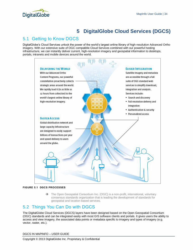
5 DigitalGlobe Cloud Services (DGCS)
5.1 Getting to Know DGCS
DigitalGlobe’s Cloud Services unlock the power of the world’s largest online library of high-resolution Advanced Ortho imagery. With our extensive suite of OGC compatible Cloud Services combined with our powerful hosting infrastructure, we can instantly deliver current, high-resolution imagery and geospatial information to desktops, portals, intranets and mobile devices around the world.
FIGURE 5.1 DGCS PROCESSES
The Open Geospatial Consortium Inc. (OGC) is a non-profit, international, voluntary consensus standards organization that is leading the development of standards for geospatial and location based services.
5.2 Things You Can Do with DGCS
The DigitalGlobe Cloud Services (DGCS) layers have been designed based on the Open Geospatial Consortium (OGC) standards and can be integrated easily with most GIS software clients and portals. It gives users the ability to access and view imagery, the associated data points or metadata specific to imagery and types of imagery (e.g. vector, raster, etc.).

MapInfo User Guide | 35
DGCS IN MAPINFO – USER GUIDE
Copyright © 2013 DigitalGlobe Inc. Proprietary & Confidential
5.2.1 SEARCH AND DISCOVERY
DigitalGlobe provides you with multiple ways to search the ImageLibrary, identify what imagery is available, and even access preview imagery for visual assessment. With these services, you can create a highly customized interface for your application, and let users discover imagery using the criteria that are important to them. DigitalGlobe supports OGC-compliant WFS, that offers metadata as well as access to low resolution imagery previews.
5.2.2 IMAGE DELIVERY
Get maximum flexibility with access to high-resolution imagery in a wide range of compressed and uncompressed formats that can be integrated into nearly any kind of geospatial application.
Supports major OGC standards, including WMS, WMTS, WCS, WFS and KML.
Compressed formats include JPEG, PNG, geospatial PDF, MrSID and more.
Uncompressed format includes GeoTIFF.
EarthService™
provides native compatibility for KML-based Earth Viewers, including Google Earth.
ImageConnect plug-in delivers georeferenced, multi-temporal imagery into your ArcGIS application via a simple yet powerful interface.
5.2.3 DATA INTEGRATION
DigitalGlobe can host your geo-located data and deliver it alongside content from our ImageLibrary. By leveraging DGCS, we can provide you with a single, centralized solution for all your geospatial applications, from Google Earth to desktop GIS, Oracle Spatial or custom enterprise applications.
5.2.4 AUTHENTICATION AND SECURITY
DigitalGlobe recognizes that geospatial data can contain very sensitive information; therefore we have implemented the necessary security measures to ensure that your data is yours alone.
128-bit SSL encryption
Access to custom imagery catalogs based on rigorous authentication
Optional behind-the-firewall solutions that can be deployed within your secure environment.
5.3 Personalized Access
DGCS enables us to create tailored imagery programs to suit your needs, from the entire globe to a set of strategic sites. Whether you are supporting navigation devices or monitoring specific areas of interest, we can deliver the right imagery, at the right time, for the right price.
5.4 Types of DGCS and Definitions
5.4.1 WEB MAP SERVICE (WMS)
The DigitalGlobe Web Map Service (WMS) provides a simple HTTPS interface for requesting geo-registered map images from one or more distributed geospatial databases. A WMS request defines the geographic layer(s) and area of interest (AOI) to be processed. The response to the request is one or more geo-registered map images (returned as JPEG, PNG, etc.) that can be displayed in a browser application. The interface also supports the ability to specify whether the returned images should be transparent so that layers from multiple servers can be combined or not.
5.4.2 WEB MAP TILE SERVICE (WMTS)
A WMTS-enabled server application can serve map tiles of spatially referenced data using tile images with predefined content, extent, and resolution.
The DigitalGlobe WMTS provides raster imagery data at multiple resolutions in predefined imagery tiles in PNG format. The Web Map Tile Service is similar to Web Map Service, but it enables better server performance in applications that involve several simultaneous requests. To improve performance, rather than creating a new image for each request, it returns small pre-generated images or reuses identical previous requests that follow a discrete set of tile matrices. This service is optimized for rapid image tile delivery for display on portals or applications where response time is of primary concern.

MapInfo User Guide | 36
DGCS IN MAPINFO – USER GUIDE
Copyright © 2013 DigitalGlobe Inc. Proprietary & Confidential
5.4.3 WEB FEATURE SERVICE (WFS)
The OGC WFS Interface Standard provides an interface allowing requests for geographical features across the web using platform-independent calls. While a WMS interface or online mapping portals like Google Maps return only an image, which end-users cannot edit or spatially analyze, the XML-based GML furnishes the default payload-encoding for transporting the geographic features. Other formats like shapefiles can also serve for transport. The OpenGIS GML Simple Features Profile is designed to increase interoperability between WFS servers and improve the ease of implementation of the WFS standard.
5.4.4 WEB COVERAGE SERVICE (WCS)
The DigitalGlobe Web Coverage Service allows the end user to directly download raster imagery data. WCS supports four types of formats, namely; Geospatial PDF, MrSID, JPEG200 and GeoTIFF. The Service treats each available product as a separate coverage; therefore the imagery returned depends on the layer being accessed. If data is requested from the current layer, then the returned imagery product is a portion of a current layer strip collection. If the data is requested from the base layer, then the returned imagery product is a portion of a base layer.
5.5 Cloud Services Data Types
The DGCS system provides access to imagery, imagery products, and imagery metadata over the World Wide Web via a suite of standards-based, OGC-compliant Cloud Services. These services provide access to products contained in DigitalGlobe’s Online Catalogs. These catalogs contain metadata describing each of the available imagery products.
The data available from these catalogs via each of the services is summarized in the table below.
TABLE 5.1 CLOUD SERVICES DATA TYPES
SERVICE TYPE OF DATA DESCRIPTION
Web Map Service Product metadata;
Raster maps
Provides product metadata and map images for the OGC Layers of the online imagery catalogs.
Web Map Tile Service Tiled raster maps Provides cached map tiles at multiple levels of resolution. Tiles are provided for specific OGC Layers.
Web Feature Service Product metadata Provides product metadata in Geographic Markup Language (GML) format for each online imagery catalog.
Web Coverage Service Full-resolution imagery Provides downloadable products for defined coverage areas; each product in the online finished product catalogs constitutes a separate coverage.
The remainder of this document describes the detailed capabilities and data provided by each of the Cloud Services.
5.6 Advantages of DGCS
5.6.1 EASY OPERABILITY
DGCS is powerful and easy to use. The advantages that emphasize easy operability are:
Compatibility with most of the leading GIS software tools
Minimal technical intervention for setting up the service
Functionalities are uncomplicated and easy for user initiation
Cloud Services can be easily integrated to custom applications, if required.
5.6.2 THE DIGITALGLOBE CONSTELLATION
DigitalGlobe owns and operates the most agile and sophisticated constellation of high-resolution commercial Earth imaging satellites. QuickBird, WorldView-1 and WorldView-2 together are capable of collecting over 500 million km2 of quality imagery per year and offering intraday revisit times around the globe. Add to that our aerial program offering wall-to-wall coverage of the U.S. and Western Europe.

MapInfo User Guide | 37
DGCS IN MAPINFO – USER GUIDE
Copyright © 2013 DigitalGlobe Inc. Proprietary & Confidential
There is no longer a question of whether timely imagery is available. If we don’t already have what you need in our vast ImageLibrary, we can get it faster than ever before. With the addition of our newest satellite, WorldView-2:
80% of tasking orders were delivered within 25 days*
80% of Select Plus tasking orders were completed within 11 days*
Our constellation features several technical advantages:
Largest sub-meter high-resolution constellation
Highest collection capacity
Outstanding geolocational accuracy
Largest high-resolution swath width
Greatest in-track stereo collection
Most spectral diversity commercially available
5.7 MapInfo System Requirements
Below are the guidelines for minimum and recommended system requirements. Note that hardware requirements do vary based on your use of the product and your system. In general, a higher processor speed, larger memory (RAM) and industry leading graphics cards provide a better user experience and result in better responses from MapInfo Professional.
Table 5.2 lists the minimum system requirements for MapInfo Professional 10.5.
TABLE 5.2 MINIMUM SYSTEM REQUIREMENTS FOR MAPINFO
OPERATING SYSTEMS MEMORY DISK SPACE GRAPHICS MONITOR
Windows XP Professional SP3
Windows Vista Ultimate SP2
Windows 7 Ultimate
Windows 7 Ultimate 64-bit
256 MB RAM with a
400 MHz Pentium
processor (1 GHz
Pentium processor
recommended)
1.5 gigabytes (GB) 16- or 24-
bit Color
800x600
Display
Windows 2008 Server
Windows 2008 Server with
XenServer
512 MB of RAM with
a 400 MHz Pentium
processor (1 GHz
Pentium processor
recommended)
2.9 gigabytes (GB) 16- or 24-
bit Color
800x600
Display
* MapInfo Professional is not currently Windows Vista certified.
The recommended system requirements for MapInfo Professional 10.5 are as follows:
TABLE 5.3 RECOMMENDED SYSTEM REQUIREMENTS
OPERATING SYSTEMS MEMORY DISK SPACE GRAPHICS MONITOR
Windows XP Professional SP3
Windows Vista Ultimate SP2
Windows 7 Ultimate
Windows 7 Ultimate 64-bit
256 or 512 MB
RAM with a
400 MHz Pentium
processor (1 GHz
Pentium processor
recommended)
Fast EIDE 2
or SCSI
Interface with
2GB or better
Data 450 MB
Mid to High 2D/3D
card with 128 MB
or better
Greater
than
1024x768
resolution
or better
Windows 2008 Server
Windows 2008 Server with XenServer
Same, PLUS
memory sufficient
to support each
connected user
Fast EIDE 2
or SCSI
Interface with
2GB or better
Data 450 MB
Server: Same
Client: Choose
based on
resolution/speed
requirements
Greater
than
1024x768
resolution
or better

MapInfo User Guide | 38
DGCS IN MAPINFO – USER GUIDE
Copyright © 2013 DigitalGlobe Inc. Proprietary & Confidential
Dependencies and Prerequisites
The MapInfo Professional install wizard, checks for the following and prompts you if not already on your system; you can choose to have the install wizard install these requirements, or cancel the installation if you do not want to proceed.
Microsoft Office Access database engine 2007 – the Access 2007 drivers (ACE)
Microsoft .NET Framework 3.5 SP1
MapInfo Professional installs a file from the Microsoft Windows Presentation Foundation (WPF) toolkit, WPFToolkit.dll file version 3.5, which is necessary for the MetaData Catalog Browser feature.
To learn more on how to install MapInfo 10.5, visit http://www.pbinsight.com/support/product-documentation/details/mapinfo-professional.
5.8 Support
DigitalGlobe has worked to simplify the process of getting your imagery-supported applications up and running quickly. We can provide you with robust documentation and SDKs to speed up the implementation process, as well as extensions to standard GIS applications. Plus, our professional services team is ready to assist you in integrating our Cloud Services into your custom enterprise environment.
Please contact DigitalGlobe at 800.496.1225 or [email protected].
5.9 References http://www.opengeospatial.org/standards
http://en.wikipedia.org/wiki/Web_Map_Service
http://en.wikipedia.org/wiki/Web_Feature_Service
http://www.opengeospatial.org/standards/wcs
http://en.wikipedia.org/wiki/GIS#OGC_standards
http://www.wikipedia.org/
http://en.wikipedia.org/wiki/Geography_Markup_Language
MapInfo User Guide | 39
DGCS IN MAPINFO – USER GUIDE
Copyright © 2013 DigitalGlobe Inc. Proprietary & Confidential
Glossary
AOI
Area of Interest. The area on the Earth that you want to view.
Bilinear Interpolation
Bilinear interpolation uses the value of the four nearest cell centers to determine the value on the output raster. The new value is a weighted average of these four values, adjusted to account for their distance from the center of the output cell. The result is a smoother-looking surface than provided by “nearest neighbor”.
Bicubic Interpolation
Bicubic interpolation combines data points on a two-dimensional grid. This method outputs the smoothest surface of all interpolation methods.
Geographic Projection
Maps longitudes as straight vertical lines and latitudes as straight horizontal lines all spaced out consistently for constant intervals.
GeoTIFF format
A GeoTIFF file is a TIFF file that is embedded with geographic data tags.
GML
Geography Markup Language. GML is XML code used to express geographical features.
Ground sample distance
The distance between the pixel centers on the ground.
JPEG2000 format
The JPEG2000 format is a JPEG format that was introduced in the year 2000. It has considerable advantages over basic JPEG format including error resilience and progressive transmission.
MrSid format
Multi-Resolution Seamless Image Database. This format compresses large raster images while maintaining the image quality.
National Imagery Transmission Format
See NITF format.
Nearest Neighbor Interpolation
Uses the value of the closest point and disregards all other values, yielding a piecewise-constant interpolant.
NITF format
National Imagery Transmission Format. A United States Department of Defense standard for transmitting and storing digital imagery.
OGC
Open GIS Consortium. An international standards organization comprised of commercial, governmental, nonprofit and research organizations. They support geospatial content development as well as data processing and sharing.
OWS
OGC Web Service Common.
Rapid R-3 Crisis (R-3) Layer
A crisis layer for emergency management that provides fast web-based access to pre- and post-event imagery of world disasters delivered to almost any desktop or web-based mapping platform. Ortho-rectified, time dominant

MapInfo User Guide | 40
DGCS IN MAPINFO – USER GUIDE
Copyright © 2013 DigitalGlobe Inc. Proprietary & Confidential
imagery strips available online within 12 hours of downlink. High-resolution satellite imagery provides the essential information required for emergency planning, risk assessment, monitoring of staging areas and emergency response, damage assessment, and recovery.
RRO
On-demand, post-processed commercial orthomosaicked imagery from QB, WV01 or WV02 over specific areas of interest to allow full utilization for mission support. This mission requires quick turnaround, often in less than 72 business hours.
Seam lines
Seam lines are the lines at which two separate images overlap. These overlapping images can be blended along the seam line to show a more uniform image.
Universal Transverse Mercator Geographic Coordinate System
See UTM.
UTM
Universal Transverse Mercator Geographic Coordinate System. UTM utilizes a two-dimensional Cartesian system to specify locations on the Earth’s surface.
WCS
Web Coverage Service.
WebCGM
Web Computer Graphics Metafile.
WFS
Web Feature Service.
WMS
Web Map Service.
WMTS
Web Map Tile Service.

MapInfo User Guide | 41
DGCS IN MAPINFO – USER GUIDE
Copyright © 2013 DigitalGlobe Inc. Proprietary & Confidential
Index
accessing WFS, 11 accuracy, description, 22 area of interest, defined, 39 BBOX. See bounding box bicubic interpolation, defined, 39 bilinear interpolation, defined, 39 bounding box
definition rules, 32 overview, 32
cloud cover, description, 22 cloud services data types, 36 coordinate system, description, 24 coverage data, description, 22 customer support, 38 datum, description, 24 deleting internet files, 17 DescribeFeatureType request
for WFS, 6 DigitalGlobe Customer Support, 38 EPSG. See European Petroleum Survey Group European Petroleum Survey Group (EPSG), 24 FinishedFeature request
for WFS, 6 geographic projection, defined, 39 GeoTIFF, defined, 39 GetCapabilities request
for WFS, 6 for WMS, 5
GetFeature request for WFS, 6
GetFeatureInfo request for WMS, 5
GetMap request for WMS, 5
GML, defined, 39 ImageInMosaicFeature request
for WFS, 6 imagery
refreshing, 17 improving performance, 17 JPEG2000, defined, 39 layers, overview, 19 MapInfo
minimum system requirements, 37 recommended system requirements, 37
MapService capability, 5 metadata, overview, 21 MrSid format, defined, 39 nearest neighbor, defined, 39 NITF format, defined, 39
off-nadir angle, description, 22 OGC, defined, 39 OWS, defined, 39 profiles, 25
accuracy, 27 cloud cover, 26 consumer, 31 currency RGB, 27 default, 25 global currency, 29 true currency, 29
projection system, overview, 23 raster data, 20 refresh, description, 22 refreshing imagery, 17 resolution, description, 22 sample URLS, 33 satellite services, content specification, 23 seam lines
defined, 40 sensors, description, 22 stacking profiles, 25 StripFeature request
for WFS, 6 support, 38 universal transverse mercator, description, 24 UTM, defined, 40 vector data, 20 WCS. See web coverage service WCS, defined, 40 web coverage service, 36 web feature service, 36 web map service, 35 web map tile service, 35 WebCGM, defined, 40 WFS. See web feature service
accessing, 11 WFS, defined, 40 WFS, introduction, 5 WMS. See web map service
accessing, 7 WMS, defined, 40 WMS, introduction, 5 WMS, version supported, 5 WMTS. See web map tile service WMTS, defined, 40 world geodetic system, description, 24 WTMSubCellFeature request
for WFS, 6 zoom levels, overview, 19


