DOPPLER SPEED LOG
DS-80
Marine Speed and Distance Measuring Equipment (SDME)
Your Local Agent/DealerYour Local Agent/Dealer
9-52 Ashihara-cho,9-52 Ashihara-cho,Nishinomiya, JapanNishinomiya, Japan
Telephone :Telephone : 0798-65-21110798-65-2111Telefax :Telefax : 0798-65-42000798-65-4200
FIRST EDITION :FIRST EDITION : FEB.FEB. 20002000Printed in JapanPrinted in JapanAll rights reserved.All rights reserved.M1M1 :: FEB.FEB. 12,200312,2003
PUB.No.PUB.No. OME-72470OME-72470*00080889601**00080889601**00080889601**00080889601*(( DAMIDAMI )) DS-80DS-80
* 0 0 0 8 0 8 8 9 6 0 1 ** 0 0 0 8 0 8 8 9 6 0 1 *
*OME72470M10**OME72470M10**OME72470M10**OME72470M10*
* O M E 7 2 4 7 0 M 1 ** O M E 7 2 4 7 0 M 1 *

i
SAFETY INSTRUCTIONS
WARNINGELECTRICAL SHOCK HAZARDDo not open the equipment.
Only qualified personnelshould work inside theequipment.
Immediately turn off the power at theswitchboard if water leaks into theequipment or an object is dropped intothe equipment.
Continued use of the equipment can causefire or electrical shock. Contact a FURUNOagent for service.
Do not place liquid-filled containers onthe top of the equipment.
Fire or electrical shock can result if theliquid spills into the equipment.
Do not disassemble or modify theequipment.
Fire, electrical shock or serious injury canresult.
Keep the equipment away from rainand water splash.
Fire or electrical shock can result if therain or water gets into the equipment.
Do not operate the equipment with wethands.
Electrical shock can result.
Keep heater away from equipment.
A heater can melt the equipment's powercord, which can cause fire or electricalshock.
Use the proper fuse.
Fuse rating is shown on the equipment.Use of a wrong fuse can result in damageto the equipment.
Do not use the equipment for other thanits intended purpose.
Improper use of the equipment can resultin personal injury or equipment damage.
Turn off the equipment immediately ifyou feel it is abnormal.
Turn off the power from the switchboard ifthe equipment is emitting strange noises or becomes excessively hot. Contact yourdealer for advice.
The useable ambient temperature rangeis 15°C to 55°C.
Do not use the equipment out of the above temperature range.
Do not place objects around theequipment.
Overheating may result.
Do not power the equipment when thetransducer is in air.
The transducer may become damaged.
Handle all units carefully.
Damage can lead to corrosion.
Do not use chemical cleaners such asalcohol, acetone and benzine to cleanthe equipment.
Chemical cleaners can remove paint andmarkings. Use only a soft, dry cloth. Forstubborn dirt, use a soft cloth moistenedwith water-diluted mild detergent.
When dry docked remove marine lifefrom the transducer.
Remove marine life to maintain goodsensitivity.
Do not paint the transducer face. Further, handle the transducer withcare.
Paint will affect equipment performance.
CAUTION
ii
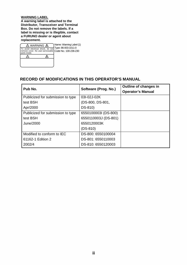
WARNING LABELA warning label is attached to the Distributor, Transceiver and TerminalBox. Do not remove the labels. If alabel is missing or is illegible, contacta FURUNO dealer or agent aboutreplacement.
WARNINGTo avoid electrical shock, do not remove cover. No user-serviceable parts inside.
Name: Warning Label (1)Type: 86-003-1011-0Code No.: 100-236-230
RECORD OF MODIFICATIONS IN THIS OPERATOR’S MANUAL
Pub No. Software (Prog. No.) Outline of changes in Operator’s Manual
Publicized for submission to type test BSH Apr/2000
03I-02J-02K (DS-800, DS-801, DS-810)
Publicized for submission to type test BSH June/2000
6550100003I (DS-800) 6550110003J (DS-801)6550120003K (DS-810)
Modified to conform to IEC 61162-1 Edition 2 2002/4
DS-800: 6550100004 DS-801: 6550110003 DS-810: 6550120003
iii
TABLE OF CONTENTSSPECIFICATIONS ....................... SP-1 FOREWORD...................................... 1 SYSTEM CONFIGURATION ............. 2 PRINCIPLE OF OPERATION............ 3 REMARKS ON USAGE..................... 4
1 OPERATION OF DISPLAY UNIT . 5 1.1 Controls........................................... 5 1.2 Turning the Power On/Off................ 5 1.3 Adjusting Contrast, Panel Dimmer... 6 1.4 Selecting a Display.......................... 6 1.5 Main Menu Operation...................... 7 1.6 Distance Run Operation .................. 7 1.7 System Setting ................................ 9 1.8 Demonstration Mode......................11
2 OPERATION OF OPTIONAL EQUIPMENT .............................. 12
2.1 Digital Indicator DS-830, Distance Indicator DS-840............................12
3 MAINTENANCE, TROUBLESHOOTING................ 14 3.1 Maintenance ..................................14 3.2 Troubleshooting .............................15 3.3 Diagnostics, Checking
Program Number ...........................16
4 DIGITAL INTERFACE (IEC 61162-1 Edition 2).............. 17 4.1 I/O Sentences ................................17 4.2 Sentence Description.....................20
5 PARTS LOCATION AND PARTS LIST................................ 23 Parts Location ......................................23 Parts List ..............................................25
CALIBRATION SHEET.................... 29 MENU OVERVIEW .......................... 30 INDEX ..................................... Index-1 Declaration of conformity

This page is intentionally left blank.

SP - 1
SPECIFICATIONS OF THE DOPPLER SPEED LOG DS-80
1. GENERAL (1) Speed Range Fore-Aft: -10.0 to +40 knots through-the-water (2) Distance Run 0.00 to 999,999.99 nautical miles through-the-water (3) Working Depth Water depth greater than 3 m beneath the keel. (4) Working Frequency 1.0 MHz (5) Speed Accuracy 1.0% or 0.1 knots whichever is the greater (6) Distance Accuracy 1.0% or 0.1 nm whichever is the greater Note: Accuracy is subject to shallow water effects, to the effect of wind, current and tide, and
sensor location. Any ultrasonic equipment having the same frequency may interfere with speed measurement. The Doppler Log transducer should be installed apart from the transducers of such kind of equipment.
2. DISPLAY UNIT (1) Display Character size 15 or 21 mm H on monochrome LCD (2) Indication
Ship’s speed Fore: **.* knots (+40.0 kt max.) Aft: **.* knots (-10.0 kt max.) Distance run ******.** nm
(3) Other Function Diagnostic check 3. DIGITAL INTERFACE (1) Serial Signal
Output: 2 ports; VBW, VLW in IEC 61162-1 (NMEA 0183 Ver 2.0) Input: 1 port; IEC 61162 (NMEA 0183 Ver 2.0)
(2) Analog Signal Speed signal for Analog display: 2 port -3.3 mA to 10 mA/ -10 kt to +30 kt Analog current output: 1 port 4 mA to 20 mA/ -10 kt to 30 kt Analog voltage output: 1 port -3.3 V to 10 V/ -10 kt to 30 kt
(3) Distance run output 2 ports; Contact closure each 0.005 nm, forward speed, 30 VDC: 0.4 A
(4) System Check signal 1 port, 30 VDC: 0.2 A, default: closed
SP - 2
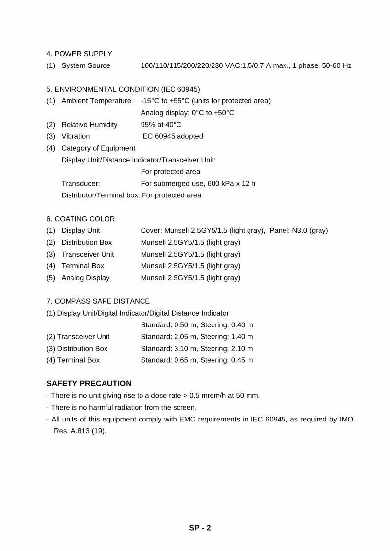
4. POWER SUPPLY (1) System Source 100/110/115/200/220/230 VAC:1.5/0.7 A max., 1 phase, 50-60 Hz 5. ENVIRONMENTAL CONDITION (IEC 60945) (1) Ambient Temperature -15°C to +55°C (units for protected area)
Analog display: 0°C to +50°C (2) Relative Humidity 95% at 40°C (3) Vibration IEC 60945 adopted (4) Category of Equipment
Display Unit/Distance indicator/Transceiver Unit: For protected area Transducer: For submerged use, 600 kPa x 12 h Distributor/Terminal box: For protected area
6. COATING COLOR (1) Display Unit Cover: Munsell 2.5GY5/1.5 (light gray), Panel: N3.0 (gray) (2) Distribution Box Munsell 2.5GY5/1.5 (light gray) (3) Transceiver Unit Munsell 2.5GY5/1.5 (light gray) (4) Terminal Box Munsell 2.5GY5/1.5 (light gray) (5) Analog Display Munsell 2.5GY5/1.5 (light gray) 7. COMPASS SAFE DISTANCE (1) Display Unit/Digital Indicator/Digital Distance Indicator
Standard: 0.50 m, Steering: 0.40 m (2) Transceiver Unit Standard: 2.05 m, Steering: 1.40 m (3) Distribution Box Standard: 3.10 m, Steering: 2.10 m (4) Terminal Box Standard: 0.65 m, Steering: 0.45 m SAFETY PRECAUTION - There is no unit giving rise to a dose rate > 0.5 mrem/h at 50 mm. - There is no harmful radiation from the screen. - All units of this equipment comply with EMC requirements in IEC 60945, as required by IMO
Res. A.813 (19).

1
FOREWORD Foreword Thank you for purchasing the FURUNO DS-80 Doppler Speed Log. We are confident you will discover why FURUNO has become synonymous with quality and reliability.
Dedicated in the design and manufacture of marine electronics equipment for half a century, FURUNO Electric Company has gained an unrivaled reputation as a world leader in the industry. This is the result of our technical excellence as well as our worldwide distribution and service network.
Please carefully read and follow the safety information and operating and maintenance instructions set forth in this manual before attempting to operate the equipment and conduct any maintenance. Your Doppler speed log will perform to the utmost of its ability only if it is operated and maintained in accordance with the correct procedures.
This equipment is designed, produced and documented by FURUNO Electric Co., Ltd., complying with ISO 9001 standards as certified by the Lloyd’s Register of Quality Assurance System.
Features The FURUNO DS-80 displays ship’s speed relative to water, using the Doppler principle; ship’s speed is measured by detecting the Doppler shift frequency from the signal returned from the watermass.
The output is interfaced with ARPA, AIS, and other shipborne equipment in IEC 61162-1 format.
The main features of the DS-80 are
• Simple operation. In most cases all that is required to display ship’s speed is to turn on the equipment.
• Pair-beam system effectively reduces error caused by pitching. The transducer assembly symmetrically emits two sonic beams, one fore and the other aft. By averaging the Doppler shift in both directions accurate speed data is available under rough sea conditions.
• Speed and distance information on the adjustable-contrast LCD display.
• Analog display, digital Indicator and digital distance indicator display optionally available.
• Conforms to the following standards: IMO A.824(19), as amended by MSC.97(72), IMO A.694(17), IEC 61023, IEC 60945 (3rd edition), IEC 61162-1 (2nd edition)..

2
SYSTEM CONFIGURATION
TRANSDUCERDS-820
DISPLAY UNITDS-800
IEC 61162-1 Input
Power ON SW SignalDistance Run SignalIEC 61162-1 Output
DIGITAL INDICATOR DS-830DISTANCE INDICATOR DS-840
: STANDARD SUPPLY
: OPTIONAL SUPPLY
DISTRIBUTION BOXDS-801
TRANSCEIVER UNIT DS-810
DIMMER MF-22L-1/MF-22L-2
TERMINAL BOXDS-802
TERMINAL BOXDS-802
DIMMER MF22L-1/MF22-2
SHIP'S MAINS115/230 VAC
RANGE SWITCH BOXDS-389
DIMMER MF-22L-1/MF-22-2
ANALOG DISPLAY UNIT MF-22A-1
115/230 VAC
JUNCTION BOXCI-630
: LOCAL SUPPLY
3
PRINCIPLE OF OPERATION
The Doppler speed log measures ship's
speed by using the Doppler Effect, which is
observed as a frequency shift resulting from
relative motion between a transmitter and
receiver or reflector of acoustic or electro-
magnetic energy. A common example of the
Doppler Effect is a train. When a train is
approaching, the whistle has a higher pitch
than normal. You can hear the change in
pitch as the train passes.
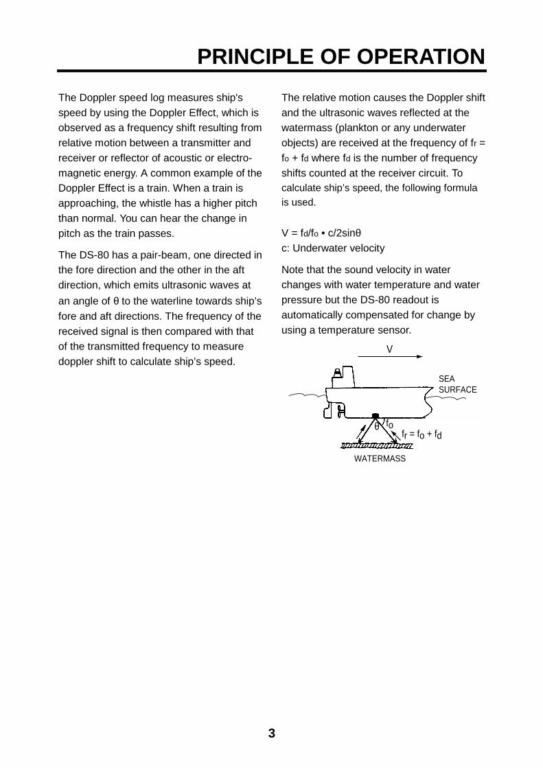
The DS-80 has a pair-beam, one directed in
the fore direction and the other in the aft
direction, which emits ultrasonic waves at
an angle of θ to the waterline towards ship’s
fore and aft directions. The frequency of the
received signal is then compared with that
of the transmitted frequency to measure
doppler shift to calculate ship’s speed.
The relative motion causes the Doppler shift
and the ultrasonic waves reflected at the
watermass (plankton or any underwater
objects) are received at the frequency of fr =
fo + fd where fd is the number of frequency
shifts counted at the receiver circuit. To
calculate ship’s speed, the following formula
is used.
V = fd/fo • c/2sinθc: Underwater velocity
Note that the sound velocity in water
changes with water temperature and water
pressure but the DS-80 readout is
automatically compensated for change by
using a temperature sensor.
V
θ fofr = fo + fd
WATERMASS
SEASURFACE

4
REMARKS ON USAGE
Remarks on Usage
The DS-80 measures ship’s speed by
detecting the Doppler shift frequency of the
echo reflected by a watermass (water layer
containing plankton and other micro-
organisms) located within the measuring
area, which is usually about 2 m. In some
instances, however, no signal is returned
because of too few plankton in the sensing
depths. This phenomenon can occur in
particular areas in particular seasons. The
probable cause is the plankton are lying in
deep water because an ice-melted cold
water mass covers the sea surface. Similar
cases may also occur in a freshwater lake.
Under these circumstances the DS-80 will
not show the correct ship’s speed.
Conditions Affecting theAccuracy(with ref to IMO A.824/3.3)
The Doppler speed log DS-80 is designed for
reliable and accurate performance through
FURUNO’s long experience and advanced
technology. It operates on the best choice of
system frequency and power output. As far as
the sonic energy is used, the performance
(accuracy) may be reduced or even lost
under:
• rough weather (may be sea state 6 or
severer)
• improper location of sensor, e.g., too close
to the propeller, thrusters, drain tubes, echo
sounder transducer
• depth under the keel if less than 3 m
The accuracy will not be affected by:
• - water temperature (sound velocity)
• salinity
• pitch/roll ±10°
Beware of Transducer Location
The transducer may be damaged if it hits
the dry dock blocks. Take the following
measures to prevent damage to the
transducer.
1. Before delivering the ship, draw up a
suitable docking plan taking into
account the dimensions and location of
the transducer. Store the plans onboard
the ship.
2. Place the dry dock blocks according to
the plan.
3. Have a diver check the position
between the transducer and the blocks
before removing the water. Confirm that
the transducer will not touch the blocks.
5
1 OPERATION OF DISPLAY UNIT
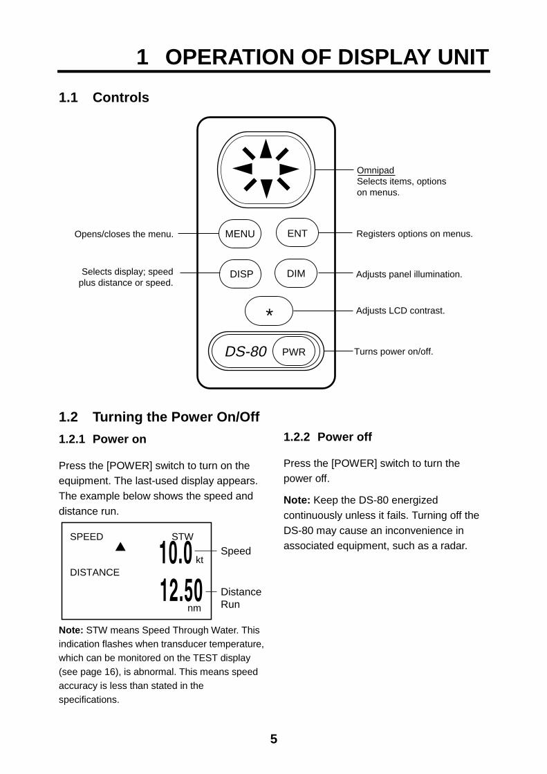
1.1 Controls
Opens/closes the menu.
Selects display; speedplus distance or speed.
Turns power on/off.
Adjusts LCD contrast.
Adjusts panel illumination.
Registers options on menus.
OmnipadSelects items, optionson menus.
MENU
PWR
ENT
DISP DIM
*
DS-80
1.2 Turning the Power On/Off
1.2.1 Power on
Press the [POWER] switch to turn on the
equipment. The last-used display appears.
The example below shows the speed and
distance run.
SPEED STW
DISTANCE
nm
10.0 12.50
Speed
DistanceRun
kt
Note: STW means Speed Through Water. This
indication flashes when transducer temperature,
which can be monitored on the TEST display
(see page 16), is abnormal. This means speed
accuracy is less than stated in the
specifications.
1.2.2 Power off
Press the [POWER] switch to turn the
power off.
Note: Keep the DS-80 energized
continuously unless it fails. Turning off the
DS-80 may cause an inconvenience in
associated equipment, such as a radar.

6
1.3 Adjusting Contrast, Panel Dimmer
1.3.1 Contrast
1. Press the [*] key to open the contrast
adjustment dialog box.
CONTRAST (0~63)
EXIT: [ENT]
41
2. Press the Omnipad at or to adjust
the contrast. The setting range is 0 to 63
and the default setting is 48.
3. Press the [ENT] key.
Note: The contrast is automatically set to
default (48) when the power is turned on.
1.3.2 Panel dimmer
1. Press the [DIM] key to show the dimmer
adjustment dialog box.
DIMMER (1~8)
EXIT: [ENT]
7
2. Press the Omnipad at or to adjust
the dimmer. The setting range is 1 to 8
and the default setting is 4.
3. Press the [ENT] key to conclude.
Note: The [DIM] key is inoperative when
dimmer is controlled externally.
1.4 Selecting a Display
Press the [DISP] key to select display
desired. Each time the key is pressed the
display shows speed and distance run or
speed alone as below.
[DISP] keyto switch
SPEED STW
DISTANCE
nm
10.0 12.50
SPEED STW
Speed
DistanceRun
kt1 0 . 0
Direction: Fore: Aft
kt
• Arrow indicates direction: indicates
fore; , aft.
• The distance run indication shows the
total distance run in forward speed only.
• The distance run is backed up when the
power is turned off.
Note: Speed error may occur in rough seas
because of air bubbles, etc.
When speed error occurs, the speed
indication freezes, and “KT” is highlighted
and blinks. If speed error continues more
than 30 seconds, the speed indication
changes to **.*.

7
1.5 Main Menu Operation
Functions of the DS-80 are selected
through the menu.
1. Press the [MENU] key to open the
menu.
MENU
DISTANCE RUN DISPLAY DEMOSYSTEM MENUSYSTEM MENU2
2. Press the Omnipad at or to select
a menu item (current selection is
highlighted) and press the [ENT] key.
For example, when DISTANCE RUN
DISPLAY is selected the following
display appears. Distance run is a form
of contact closure, 200 pulses/nm. To
select IEC 61162 sentence, see
paragraph 1.6.1.
DISTANCE RUN DISPLAY
DATA DISPLAY CONTACT CLOSURERESET OFFSET 0.00nm
ENT SET
3. Press the Omnipad at or to select
the menu item desired and press the
[ENT] key. For example select RESET.
DISTANCE RUN DISPLAY
DATA DISPLAY CONTACT CLOSURERESET OFFSET
OFFON
4. Press the Omnipad at or to select
the menu option desired and press the
[ENT] key.
5. Press the [MENU] key twice to close the
menu. (Some menus require only a
single pressing of the [MENU] key.)
To enter numerical data
Some menus require input of numeric data.
This is done with the Omnipad.
1. Select the digit or sign (+ or -) to change
with or on the Omnipad. (The
cursor shows the digit or sign selected.)
2. Enter a figure at each digit by hitting the
Omnipad at or . The example
below shows the DISTANCE RUN
DISPLAY menu, where you may adjust
the distance run indication for SET.
DISTANCE RUN DISPLAY
DATA DISPLAY CONTACT CLOSURERESET OFFSET 000000.00nm
ENT SETCursor
3. Press the [ENT] key to conclude.
1.6 Distance Run Operation
The operator may adjust and reset the
distance run indication and select display
method.
1.6.1 Selecting display method
The default setting provides for independent
display and adjustment of the distance run
indication on all displays (display unit,
Digital Indicator, distance indicator).
To show the same distance run indication
on all displays do the following:
1. Press the [MENU] key to open the
menu.
8
MENU
DISTANCE RUN DISPLAY DEMOSYSTEM MENUSYSTEM MENU2
2. Press the Omnipad at to select
DISTANCE RUN DISPLAY and press
the [ENT] key.
DISTANCE RUN DISPLAY
DATA DISPLAY CONTACT CLOSURERESET OFFSET 0.00nm
ENT SET
3. Select DATA DISPLAY and press the
[ENT] key.
DISTANCE RUN DISPLAY
DATA DISPLAYCONTACT CLOSURERESET OFFSET 0.00 nm ENT SET
IEC61162(VLW)CONTACT CLOSURE
4. Press to select IEC 61162(VLW)
and press the [ENT] key.
5. Press the [MENU] key twice to close the
menu.
1.6.2 Adjusting distance run
Distance run can be changed when the
menu item DATA DISPLAY is selected to
CONTACT CLOSURE. It may also be
changed only at the display unit when IEC
61162(VLW) is selected. .
1. Press the [MENU] key to open the
menu.
2. Use to select DISTANCE RUN
DISPLAY and press the [ENT] key.
3. Select SET and press the [ENT] key.
The cursor circumscribes the leftmost
digit of the distance run figure.
DISTANCE RUN DISPLAY
DATA DISPLAY CONTACT CLOSURERESET OFFSET 000000.00nm
ENT SETCursor
4. Press the Omnipad at or to select
the digit to change.
5. Press the Omnipad at or to
change value. The setting range is 0.00
nm to 999999.99 nm.
6. Press the [ENT] key followed by
pressing the [MENU] key twice to
conclude your selection and close the
menu.
1.6.3 Resetting distance run to zero
Distance run can be reset to zero when the
menu item DATA DISPLAY is selected to
CONTACT CLOSURE. It may also be reset
to zero only at the display unit when IEC
61162(VLW) is selected.
1. Press the [MENU] key to open the
menu.
2. Press the Omnipad at to select
DISTANCE RUN DISPLAY and press
the [ENT] key.
3. Select RESET and press the [ENT] key.
DISTANCE RUN DISPLAY
DATA DISPLAY CONTACT CLOSURERESET OFFSET
OFFON
4. Press the Omnipad at to select ON.

9
5. Press the [ENT] key to finish and press
the [MENU] key twice to close the
menu.
The distance run indication reads 0.00.
1.7 System Setting
The system setting provides the
fundamental parameters for intended
performance of the DS-80.
1.7.1 Displaying the system menu
1. Press the [MENU] key to open the
menu.
2. Select SYSTEM MENU and press the
[ENT] key.
SYSTEM MENU
SHIP SPEED AVG 15 SECSPEED OFFSET +0.0%TRACK DEPTH 2.0 mXDR OFFSET +00˚SPD DATA SELECT DOPPLER ENT: SET
1.7.2 Ship speed average
Wind and currents affect ship’s speed, and
speed data is averaged over the time period
set on this menu. Increase the speed
averaging period if the speed reading is
unstable.
1. Open the SYSTEM MENU.
2. Select SHIP SPEED AVG and press the
[ENT] key. 15 SEC30 SEC45 SEC60 SEC
3. Select averaging time period desired
among 15, 30, 45 and 60 seconds.
4. Press the [ENT] key.
5. Press the [MENU] key twice to close the
menu.
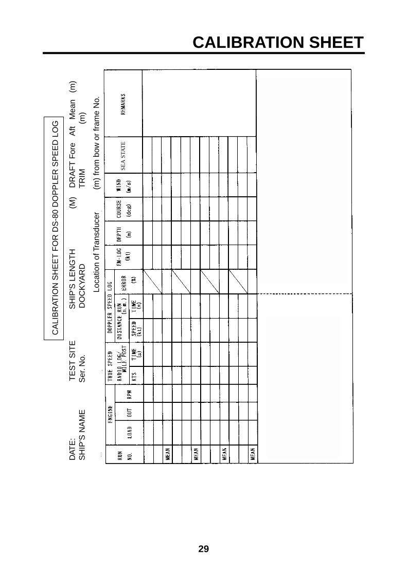
1.7.3 Speed offset (calibration)
Calibration of any speed log is necessary
through the sea trials during the
commissioning tests. Fill in the calibration
sheet which is on page 25 of this manual.
Us the resultant data to calculate speed
offset and enter it as below. The setting
range is -25.0% to +25.0%.
1. Open the SYSTEM MENU.
2. Select SPEED OFFSET and press the
[ENT] key.
SYSTEM MENU
SHIP SPEED AVG 30 SECSPEED OFFSET +0.0%TRACK DEPTH 2.0 mXDR OFFSET +00˚SPD DATA SELECT DOPPLER ENT: SET
3. Select the digit to change with or
and change the value with or on
the Omnipad.
4. Press the [ENT] key.
5. Press the [MENU] key twice to close the
menu.
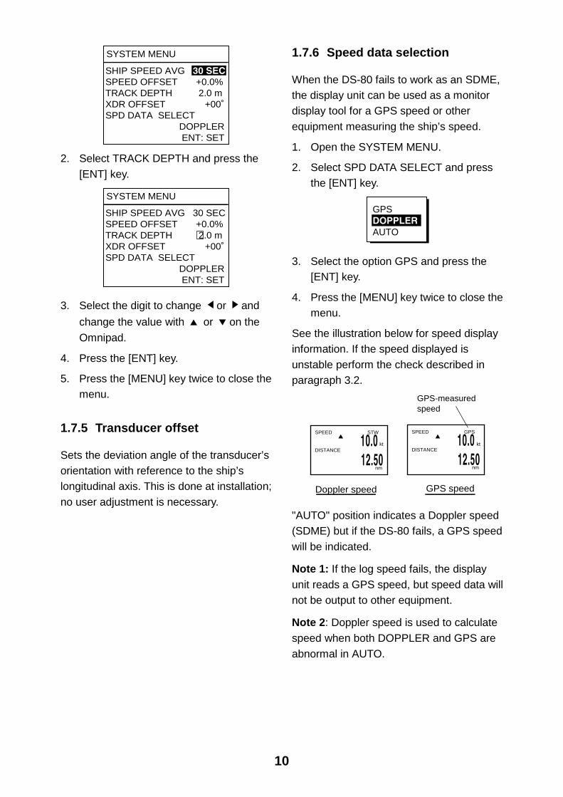
1.7.4 Tracking depth
Doppler shift measuring depth in the DS-80
is 2 m at default. If the speed readout is
unstable due to air bubbles near the ship’s
hull, increase or decrease the track depth to
stabilize the readout. The setting range is
1.0 m to 9.9 m.
1. Open the SYSTEM MENU.
10
SYSTEM MENU
SHIP SPEED AVG 30 SECSPEED OFFSET +0.0%TRACK DEPTH 2.0 mXDR OFFSET +00˚SPD DATA SELECT DOPPLER ENT: SET
2. Select TRACK DEPTH and press the
[ENT] key.
SYSTEM MENU
SHIP SPEED AVG 30 SECSPEED OFFSET +0.0%TRACK DEPTH 2.0 mXDR OFFSET +00˚SPD DATA SELECT DOPPLER ENT: SET
3. Select the digit to change or and
change the value with or on the
Omnipad.
4. Press the [ENT] key.
5. Press the [MENU] key twice to close the
menu.
1.7.5 Transducer offset
Sets the deviation angle of the transducer’s
orientation with reference to the ship’s
longitudinal axis. This is done at installation;
no user adjustment is necessary.
1.7.6 Speed data selection
When the DS-80 fails to work as an SDME,
the display unit can be used as a monitor
display tool for a GPS speed or other
equipment measuring the ship’s speed.
1. Open the SYSTEM MENU.
2. Select SPD DATA SELECT and press
the [ENT] key.
GPSDOPPLERAUTO
3. Select the option GPS and press the
[ENT] key.
4. Press the [MENU] key twice to close the
menu.
See the illustration below for speed display
information. If the speed displayed is
unstable perform the check described in
paragraph 3.2.
SPEED STW
DISTANCE
nm
10.0 12.50
Doppler speed
SPEED GPS
DISTANCE
nm
10.0 12.50
GPS speed
GPS-measured speed
kt kt
"AUTO" position indicates a Doppler speed
(SDME) but if the DS-80 fails, a GPS speed
will be indicated.
Note 1: If the log speed fails, the display
unit reads a GPS speed, but speed data will
not be output to other equipment.
Note 2: Doppler speed is used to calculate
speed when both DOPPLER and GPS are
abnormal in AUTO.
11
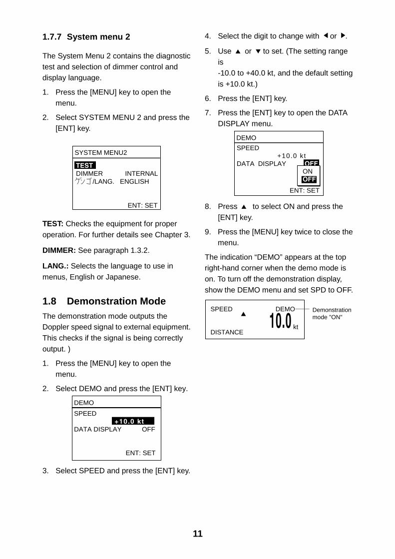
1.7.7 System menu 2
The System Menu 2 contains the diagnostic
test and selection of dimmer control and
display language.
1. Press the [MENU] key to open the
menu.
2. Select SYSTEM MENU 2 and press the
[ENT] key.
SYSTEM MENU2
TESTDIMMER INTERNAL /LANG. ENGLISH
ENT: SET
TEST: Checks the equipment for proper
operation. For further details see Chapter 3.
DIMMER: See paragraph 1.3.2.
LANG.: Selects the language to use in
menus, English or Japanese.
1.8 Demonstration Mode
The demonstration mode outputs the
Doppler speed signal to external equipment.
This checks if the signal is being correctly
output. )
1. Press the [MENU] key to open the
menu.
2. Select DEMO and press the [ENT] key.
DEMO
SPEED +10.0 ktDATA DISPLAY OFF
ENT: SET
3. Select SPEED and press the [ENT] key.
4. Select the digit to change with or .
5. Use or to set. (The setting range
is
-10.0 to +40.0 kt, and the default setting
is +10.0 kt.)
6. Press the [ENT] key.
7. Press the [ENT] key to open the DATA
DISPLAY menu.
DEMO
SPEED +10.0 ktDATA DISPLAY OFF
ENT: SET
ONOFF
8. Press to select ON and press the
[ENT] key.
9. Press the [MENU] key twice to close the
menu.
The indication “DEMO” appears at the top
right-hand corner when the demo mode is
on. To turn off the demonstration display,
show the DEMO menu and set SPD to OFF.
SPEED DEMO
DISTANCE10.0
Demonstrationmode "ON"
kt
12
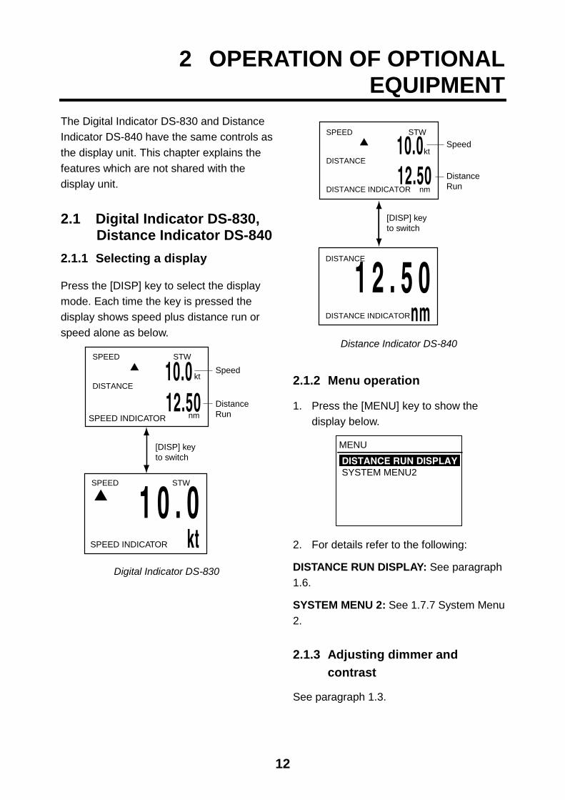
2 OPERATION OF OPTIONALEQUIPMENT
The Digital Indicator DS-830 and Distance
Indicator DS-840 have the same controls as
the display unit. This chapter explains the
features which are not shared with the
display unit.
2.1 Digital Indicator DS-830, Distance Indicator DS-840
2.1.1 Selecting a display
Press the [DISP] key to select the display
mode. Each time the key is pressed the
display shows speed plus distance run or
speed alone as below.
[DISP] keyto switch
SPEED STW
DISTANCE
nm
10.0 12.50
SPEED STW
1 0 . 0kt
Speed
DistanceRunSPEED INDICATOR
SPEED INDICATOR
kt
Digital Indicator DS-830
SPEED STW
DISTANCE
DISTANCE INDICATOR nm
10.0 12.50
DISTANCE
DISTANCE INDICATOR
1 2 . 5 0nm
[DISP] keyto switch
Speed
DistanceRun
kt
Distance Indicator DS-840
2.1.2 Menu operation
1. Press the [MENU] key to show the
display below.
MENU
DISTANCE RUN DISPLAYSYSTEM MENU2
2. For details refer to the following:
DISTANCE RUN DISPLAY: See paragraph
1.6.
SYSTEM MENU 2: See 1.7.7 System Menu
2.
2.1.3 Adjusting dimmer and
contrast
See paragraph 1.3.
13
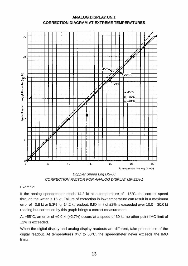
ANALOG DISPLAY UNIT
CORRECTION DIAGRAM AT EXTREME TEMPERATURES
Doppler Speed Log DS-80
CORRECTION FACTOR FOR ANALOG DISPLAY MF-22A-1
Example:
If the analog speedometer reads 14.2 kt at a temperature of –15°C, the correct speed
through the water is 15 kt. Failure of correction in low temperature can result in a maximum
error of –0.8 kt or 5.3% for 14.2 kt readout. IMO limit of ±2% is exceeded over 10.0 – 30.0 kt
reading but correction by this graph brings a correct measurement.
At +55°C, an error of +0.0 kt (+2.7%) occurs at a speed of 30 kt; no other point IMO limit of
±2% is exceeded.
When the digital display and analog display readouts are different, take precedence of the
digital readout. At temperatures 0°C to 50°C, the speedometer never exceeds the IMO
limits.
14
3 MAINTENANCE, TROUBLESHOOTING
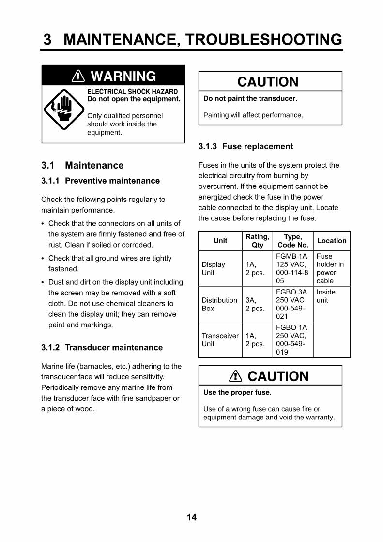
WARNINGELECTRICAL SHOCK HAZARDDo not open the equipment.
Only qualified personnelshould work inside theequipment.
3.1 Maintenance 3.1.1 Preventive maintenance
Check the following points regularly to maintain performance.
• Check that the connectors on all units of the system are firmly fastened and free of rust. Clean if soiled or corroded.
• Check that all ground wires are tightly fastened.
• Dust and dirt on the display unit including the screen may be removed with a soft cloth. Do not use chemical cleaners to clean the display unit; they can remove paint and markings.
3.1.2 Transducer maintenance
Marine life (barnacles, etc.) adhering to the transducer face will reduce sensitivity. Periodically remove any marine life from the transducer face with fine sandpaper or a piece of wood.
CAUTIONDo not paint the transducer.
Painting will affect performance.
3.1.3 Fuse replacement
Fuses in the units of the system protect the electrical circuitry from burning by overcurrent. If the equipment cannot be energized check the fuse in the power cable connected to the display unit. Locate the cause before replacing the fuse.
Unit Rating,Qty
Type, Code No. Location
Display Unit
1A, 2 pcs.
FGMB 1A 125 VAC, 000-114-805
Fuse holder in power cable
Distribution Box
3A, 2 pcs.
FGBO 3A 250 VAC 000-549- 021
Transceiver Unit
1A, 2 pcs.
FGBO 1A 250 VAC, 000-549- 019
Inside unit
CAUTIONUse the proper fuse.
Use of a wrong fuse can cause fire orequipment damage and void the warranty.
15
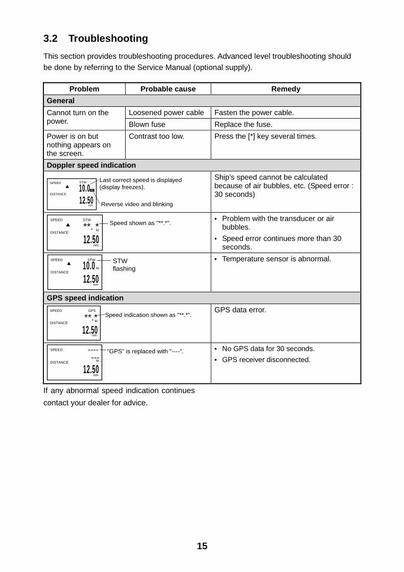
3.2 Troubleshooting This section provides troubleshooting procedures. Advanced level troubleshooting should be done by referring to the Service Manual (optional supply).
Problem Probable cause Remedy General
Loosened power cable Fasten the power cable. Cannot turn on the power. Blown fuse Replace the fuse. Power is on but nothing appears on the screen.
Contrast too low. Press the [*] key several times.
Doppler speed indication
10.0 12.50
SPEED
DISTANCE
nm
Last correct speed is displayed(display freezes).
Reverse video and blinking
kt
STW
Ship’s speed cannot be calculated because of air bubbles, etc. (Speed error : 30 seconds)
SPEED
DISTANCE
nm
**. *
12.50
Speed shown as "**.*".kt
STW
• Problem with the transducer or air bubbles.
• Speed error continues more than 30 seconds.
SPEED STW
DISTANCE
nm
10.0 12.50
STWflashingkt
• Temperature sensor is abnormal.
GPS speed indication
**.*
12.50
SPEED GPS
DISTANCE
nm
Speed indication shown as "**.*".kt
GPS data error.
SPEED
DISTANCE
nm12.50
"GPS" is replaced with "----".----kt---
• No GPS data for 30 seconds. • GPS receiver disconnected.
If any abnormal speed indication continues contact your dealer for advice.
16
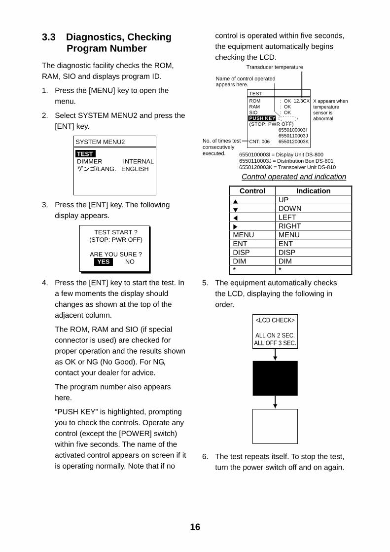
3.3 Diagnostics, Checking Program Number The diagnostic facility checks the ROM, RAM, SIO and displays program ID.
1. Press the [MENU] key to open the menu.
2. Select SYSTEM MENU2 and press the [ENT] key.
SYSTEM MENU2
TESTDIMMER INTERNAL
/LANG. ENGLISH
3. Press the [ENT] key. The following
display appears.
TEST START ?(STOP: PWR OFF)
ARE YOU SURE ?YES NO
4. Press the [ENT] key to start the test. In
a few moments the display should changes as shown at the top of the adjacent column.
The ROM, RAM and SIO (if special connector is used) are checked for proper operation and the results shown as OK or NG (No Good). For NG, contact your dealer for advice.
The program number also appears here.
“PUSH KEY” is highlighted, prompting you to check the controls. Operate any control (except the [POWER] switch) within five seconds. The name of the activated control appears on screen if it is operating normally. Note that if no
control is operated within five seconds, the equipment automatically begins checking the LCD.
TEST
ROM : OK 12.3CXRAM : OKSIO : OK PUSH KEY(STOP: PWR OFF)
6550100003I6550110003J
CNT: 006 6550120003KNo. of times testconsecutivelyexecuted.
Name of control operatedappears here.
6550100003I = Display Unit DS-8006550110003J = Distribution Box DS-8016550120003K = Transceiver Unit DS-810
Transducer temperature
X appears whentemperaturesensor isabnormal
Control operated and indication
Control Indication UP DOWN LEFT RIGHT
MENU MENU ENT ENT DISP DISP DIM DIM * *
5. The equipment automatically checks the LCD, displaying the following in order.
<LCD CHECK>
ALL ON 2 SEC.ALL OFF 3 SEC.
6. The test repeats itself. To stop the test, turn the power switch off and on again.

17
4 DIGITAL INTERFACE (IEC 61162-1 Edition 2)
4.1 I/O Sentences Input sentences of IEC61162_RX port GGA, VTG
Output sentences of IEC61162_TX1, IEC61162_TX2 ports VBW, VLW (Talker: VD)
Transmission interval 3 s for VBW; 1 s for VLW
Data transmission
Data is transmitted in serial asynchronous form in accordance with the standard referenced in 2.1 of IEC 61162-1. The first bit is a start bit and is followed by data bits, least-significant-bit as illustrated below. The following parameters are used: Baud rate: 4800 Data bits: 8 (D7 = 0), parity none Stop bits: 1
D0 D1 D2 D3 D4 D5 D6 D7
Startbit
StopbitData bits

18
Schematic diagrams
IEC61162 RX port
DS-801
65P6010
1112
.
.
.
.
.
.
TB3F2047A-20P-B
IEC61162_RX_AIEC61162_RX_B
<11<<12<
JP6ERJ_6GEY0R00V
R121 22Ω
R122 120ΩR123 120 ΩR124 22Ω
1 2
CR17 1SS181
4
5
6
1
3
JP7ERJ_6GEY0R00V
PC400U42
Load requirements as listener
Isolation: Optocoupler Input Impedance: 44 ohms Max. Voltage: ±2.6V Threshold: 4 mA
IEC61162 TX1 port
Output drive capability
Max. 20 mA

19
IEC61162 TX2 port
DS-801
65P6010
10 9
.
.
.
.
.
.
.
.
TB3F2047A-20P-B
IEC61162_TX2_AIEC61162_TX2_B
<7<<8<
R13647
R13547
87
U43SN75ALS191PS
2
Vcc1
4
Output drive capability
Max. 20 mA

20
4.2 Sentence Description GGA - Global positioning system (GPS) fix data
Time, position and fix related data for a GPS receiver.
Note: Item Only GPS quality indicator and antenna altitude above/below are used.
21
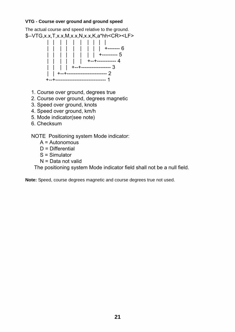
VTG - Course over ground and ground speed
The actual course and speed relative to the ground. $--VTG,x.x,T,x.x,M,x.x,N,x.x,K,a*hh<CR><LF> | | | | | | | | | | | | | | | | | | | +------- 6 | | | | | | | | +--------- 5 | | | | | | +--+----------- 4 | | | | +--+----------------- 3 | | +--+----------------------- 2 +--+----------------------------- 1
1. Course over ground, degrees true 2. Course over ground, degrees magnetic 3. Speed over ground, knots 4. Speed over ground, km/h 5. Mode indicator(see note) 6. Checksum
NOTE Positioning system Mode indicator: A = Autonomous D = Differential S = Simulator N = Data not valid The positioning system Mode indicator field shall not be a null field.
Note: Speed, course degrees magnetic and course degrees true not used.

22
VBW - Dual ground/water speed Water-referenced and ground-referenced speed data.
$--VBW,x.x,x.x,A,x.x,x.x,A,x.x,A,x.x,A*hh<CR><LF> | | | | | | | | | | | | | | | | | | | | | +--- 11 | | | | | | | | | +----- 10 | | | | | | | | +-------- 9 | | | | | | | +----------- 8 | | | | | | +-------------- 7 | | | | | +----------------- 6 | | | | +-------------------- 5 | | | +------------------------ 4 | | +--------------------------- 3 | +------------------------------ 2 +---------------------------------- 1
1. Longitudial water speed, knots 2. Transverse water speed, knots 3. Status: water speed, A=data valid V=data invalid 4. Longitudial ground speed, knots 5. Transverse ground speed, knots 6. Status: ground speed, A=data valid V=data invalid 7. Stern transverse water speed, knots 8. Status: stern water speed, A=data valid V=data invalid 9. Stern transverse ground speed, knots 10. Status: stern ground speed, A=data valid V=data invalid 11. Checksum Notes
1. Longitudinal speed: “-” astern.
* Not used.
VLW - Distance travelled through the water The distance travelled, relative to the water.
$--VLW,x.x,N,x.x,N*hh<CR><LF> | | | | | | | | | +--------- 3 | | +--+----------- 2 +--+----------------- 1
1. Total cumulative distance, nautical miles 2. Distance since reset, nautical miles 3. Checksum

23
5 PARTS LOCATION AND PARTS LISTParts Location Display unit DS-800
U10 (ROM)
ICP Board 65P6000, parts side
Distribution box DS-801
From right TB1, TB2, TB3
JPW Board
POWERswitch
TB101
Distribution Box DS-801, inside view

24
Transceiver unit DS-810
KCP Board
POWERSwitch
TB101TB1
Transceiver Unit DS-810, inside view
25
Parts List This equipment contains complex modules in which fault diagnosis and repair down to component level are not practicable (IMO A.694(17)/8.3.1). Only some discrete components are used. FURUNO ELECTRIC CO., LTD. believes identifying these components is of no use for shipborne maintenance; therefore, they are not listed in this manual. Major modules can be located on parts location photos on the preceding page.

26
Model DS-80Unit DISPLAY UNIT DS-800
ELECTRICAL PARTS LIST Ref.Dwg. C3441-K01-C2000-01 Block.No.
SYMBOL TYPE CODE No. REMARKS SHIPPABLEASSEMBLY
PRINTED CIRCUIT BOARD65P6000, ICP 000-142-649 X
CABLE w/CONNECTORMJ-A7SPF-005-020 000-139-384 20S0251MJ-A6SPF-003-020 000-142-658 65S1231MJ-PH 6P 000-142-659 65S1227MJ-PH 7P 000-142-660 65S1228
27
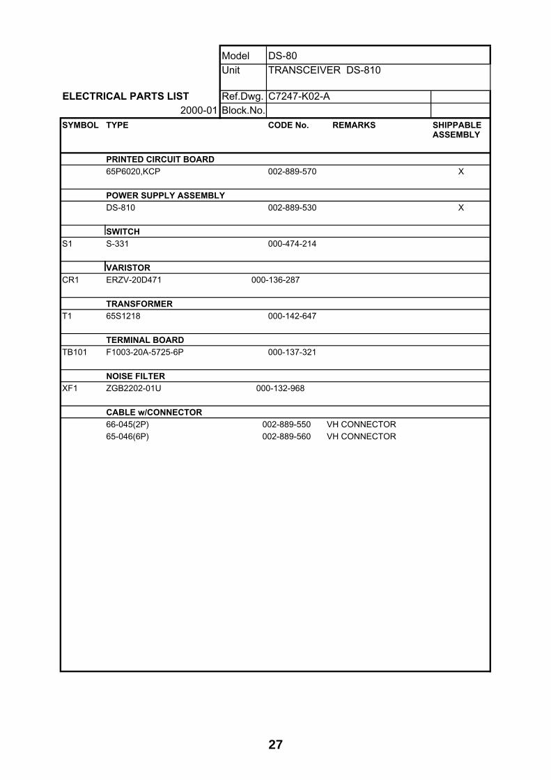
Model DS-80Unit TRANSCEIVER DS-810
ELECTRICAL PARTS LIST Ref.Dwg. C7247-K02-A2000-01 Block.No.
SYMBOL TYPE CODE No. REMARKS SHIPPABLEASSEMBLY
PRINTED CIRCUIT BOARD65P6020,KCP 002-889-570 X
POWER SUPPLY ASSEMBLYDS-810 002-889-530 X
SWITCHS1 S-331 000-474-214
VARISTORCR1 ERZV-20D471 000-136-287
TRANSFORMERT1 65S1218 000-142-647
TERMINAL BOARDTB101 F1003-20A-5725-6P 000-137-321
NOISE FILTERXF1 ZGB2202-01U 000-132-968
CABLE w/CONNECTOR66-045(2P) 002-889-550 VH CONNECTOR65-046(6P) 002-889-560 VH CONNECTOR

28
Model DS-80Unit DISTRIBUTOR DS-801
ELECTRICAL PARTS LIST Ref.Dwg. C7247-K03-A2000-01 Block No.
SYMBOL TYPE CODE No. REMARKS SHIPPABLEASSEMBLY
PRINTED CIRCUIT BOARD65P6010,JPW 002-889-490 X
ASSEMBLYDS-801 002-889-470 POWER SUPPLY X
POWER SUPPLY ASSEMBLYDS-801-100 002-889-410 X
DS-801-110 002-889-420 X
DS-801-115 002-889-430 X
DS-801-200 002-889-440 X
DS-801-220 002-889-450 X
DS-801-230 002-889-460 X
SWITCHS1 S-331 000-474-214
VARISTORCR1 ERZV-20D471 000-136-287
TERMINAL BOARDTB101 F1003-20A-2P 000-142-631
FUSE HOLDERF1 FH-001AF 000-138-909
POWER SUPPLYPD1 FAW-24-2R1 000-142-633
NOISE FILTERXF1 ZAC2210-11 000-120-155
29
CALIBRATION SHEET C
ALI
BR
ATIO
N S
HE
ET
FO
R D
S-8
0 D
OP
PLE
R S
PE
ED
LO
G
DAT
E:
TE
ST
SIT
E
S
HIP
'S L
EN
GT
H
(M
)
DR
AF
T F
ore
Aft
Mea
n (
m)
SH
IP'S
NA
ME
Ser
. No.
D
OC
KYA
RD
T
RIM
(m
)
.
DS
-80
Loca
tion
of T
rans
duce
r
(m)
from
bow
or
fram
e N
o.
SEA
STA
TE
30
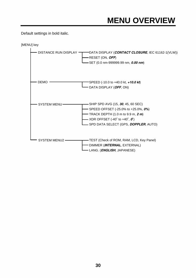
MENU OVERVIEW Default settings in bold italic.
[MENU] key
DISTANCE RUN DISPLAY DATA DISPLAY (CONTACT CLOSURE, IEC 61162-1(VLW))
RESET (ON, OFF)
SET (0.0 nm-999999.99 nm, 0.00 nm)
DEMO
SYSTEM MENU SHIP SPD AVG (15, 30, 45, 60 SEC)
SPEED OFFSET (-25.0% to +25.0%, 0%)
TRACK DEPTH (1.0 m to 9.9 m, 2 m)
XDR OFFSET (-40˚ to +40˚, 0˚)
SPD DATA SELECT (GPS, DOPPLER, AUTO)
SYSTEM MENU2 TEST (Check of ROM, RAM, LCD, Key Panel)
DIMMER (INTERNAL, EXTERNAL)
LANG. (ENGLISH, JAPANESE)
SPEED (-10.0 to +40.0 kt, +10.0 kt)
DATA DISPLAY (OFF, ON)

Index-1
INDEX
C
Contrast .......................................................... 6
Control description ......................................... 5
D
Demonstration mode...................................... 9
Diagnostics................................................... 14
Digital indicator............................................. 12
Digital interface............................................. 16
Digitial display .............................................. 12
DIM key .......................................................... 6
Dimmer........................................................... 6
Distance run
adjusting ..................................................... 9
display method............................................ 8
resetting to zero.......................................... 8
F
Fuse replacement......................................... 13
M
Maintenance................................................. 13
MENU key ...................................................... 7
Menu operation .............................................. 7
Menu tree ..................................................... 24
P
Parts list ........................................................20
Parts location ................................................18
POWER switch ...............................................5
S
Ship's speed
averaging time.............................................9
offset..........................................................10
source........................................................11
System configuration ......................................2
System menu..................................................9
System menu2..............................................11
T
Transducer
maintenance..............................................13
position offset ............................................10
Troubleshooting ............................................14
U
UNIT key .........................................................7
W
Water tracking depth.....................................10
![MIL-S-901D [SHOCK TESTS. H.I. (HIGH-IMPACT) SHIPBOARD ...€¦ · mil-s-901d [shock tests. h.i. (high-impact) shipboard machinery, equipment, and systems, requiremen...] author: usa](https://cdn.vdocument.in/doc/165x107/5eac88b75c12056feb5068ed/mil-s-901d-shock-tests-hi-high-impact-shipboard-mil-s-901d-shock-tests.jpg)


