
MATERIAL SPECIFICATION FOR HIGH DENSITY POLYETHYLENE (HDPE) PIPE &
FITTINGS
SPECIFICATION SAJ PS / HDPE / 001
(Rev.5.0 /12.2018)
QUALITY ASSURANCE DEPARTMENT RANHILL SAJ SDN. BHD.
NO CHANGES ALLOWED WITHOUT THE PERMISSION OF QUALITY ASSURANCE DEPARTMENT
OF RANHILL SAJ SDN BHD .
Ref. No. : PS/HDPE/001
Date : 24/12/2018
Total Pages : 15/15

QUALITY ASSURANCE DEPARTMENT RANHILL SAJ SDN. BHD.
SAJ PS/HDPE/001 (Rev5.0 / 12.2018) NO CHANGES ALLOWED WITHOUT THE PERMISSION OF
QUALITY ASSURANCE DEPARTMENT OF RANHILL SAJ SDN BHD Page 2
MATERIAL SPECIFICATION FOR HIGH DENSITY POLYETHYLENE (HDPE) PIPE & FITTINGS
CONTENT Page
1.0 GENERAL 4
2.0 MATERIAL 4
3.0 COLOUR 4
4.0 CLASSIFICATION AND DIMENSION OF PIPES 4
5.0 TOLERANCES 5
6.0 LENGTH 5
7.0 APPEARANCE 5
8.0 TESTING REQUIREMENTS 6
9.0 MARKING OF PIPES 10
10.0 PIPE FITTINGS 10
11.0 HDPE PIPE JOINTING 12
12.0 STORAGE 13
13.0 PRE-DELIVERY INSPECTION 15
14.0 CERTIFICATION 15

QUALITY ASSURANCE DEPARTMENT RANHILL SAJ SDN. BHD.
SAJ PS/HDPE/001 (Rev5.0 / 12.2018) NO CHANGES ALLOWED WITHOUT THE PERMISSION OF
QUALITY ASSURANCE DEPARTMENT OF RANHILL SAJ SDN BHD Page 3
MATERIAL SPECIFICATION FOR HIGH DENSITY POLYETHYLENE (HDPE) PIPE & FITTINGS
This specification is applicable to High Density Polyethylene (HDPE) Pipe for water supply systems and shall conform to the relevant standards listed below:
MS 1058: Part 2: 2005 Polyethylene (PE) Piping System for Water Supply – Part 2: Pipes (Fourth Revision)
MS 1058: Part 3: 2006 Polyethylene (PE) Piping System for Water Supply – Part 3: General (Fourth Revision)
JKR 20200-0053-99 JKR Tender Specification for Polyethylene (PE) Pipe Systems for Water Supply
BS EN 12201-3: 2011+A1:2012
Plastics Piping System for Water Supply and for Drainage and Sewerage Under Pressure
ISO 1133 Plastics – Determination of melt mass-flow rate (MFR) and melt volume-flow rate (MVR) of thermoplastics – Part 1: Standard method
EN 728 Plastics piping and ducting system. Polyolefin pipes and fittings. Determination of oxidation induction time
EN 921
Plastics piping system. Thermoplastics pipes. Determination of resistance to internal pressure at constant temperature.

QUALITY ASSURANCE DEPARTMENT RANHILL SAJ SDN. BHD.
SAJ PS/HDPE/001 (Rev5.0 / 12.2018) NO CHANGES ALLOWED WITHOUT THE PERMISSION OF
QUALITY ASSURANCE DEPARTMENT OF RANHILL SAJ SDN BHD Page 4
MATERIAL SPECIFICATION FOR HIGH DENSITY POLYETHYLENE (HDPE) PIPE & FITTINGS 1.0 GENERAL
1.1 This specification is applicable to High Density Polyethylene Pipe for water supply systems and shall conform to MS 1058: Part 2: 2005, MS 1058: Part 3: 2006, BS EN 12201-3 and JKR Standard Specification JKR 20200-0053-99.
1.2 These specifications will provide necessary information on the product dimension and
requirements for the supply of pipes only. 2.0 MATERIAL
2.1 The High Density Polyethylene (HDPE) Pipe shall be made from base polymer and shall
conform to the requirements as specified in MS 1058 Part 2: 2005.
2.2 The base polymer shall be a single grade of polyethylene, PE 100 with a derived density
greater than 0.93g/cm3 tested at 20°C.
2.3 No rework material is allowed to be used for the manufacture of the pipes.
2.4 No additives that can contribute to toxic hazard, impair the fabrication of properties and
chemical and physical properties in particular to long term mechanical and strength is
allowed.
3.0 COLOUR
3.1 The colour of the pipes shall be black with blue stripes. The material for stripes shall be of the same type of resin as used in the compound for the pipe.
4.0 CLASSIFICATION AND DIMENSION OF PIPES
4.1 All High Density Polyethylene (HDPE) Pipes must be from class PE 100 and minimum strength at 20°C with
4.1.1 Nominal Pressure (PN) 16 and Standard Dimensions Ratio (SDR) 11 4.2 Wall thickness and nominal diameter of PE 100 are given in the table below.

QUALITY ASSURANCE DEPARTMENT RANHILL SAJ SDN. BHD.
SAJ PS/HDPE/001 (Rev5.0 / 12.2018) NO CHANGES ALLOWED WITHOUT THE PERMISSION OF
QUALITY ASSURANCE DEPARTMENT OF RANHILL SAJ SDN BHD Page 5
Table 1: Diameter and wall thickness for PE100, SDR 11, PN 16 pipe series
Nominal Diameter for
PE Pipes (mm)
Wall thickness (mm)
Internal Diameter (mm) Outside Diameter (mm)
Min Max
20 2.0 2.3 16.0 20
25 2.3 2.7 20.4 25
32 3.0 3.4 26.0 32
40 3.7 4.2 32.6 40
50 4.6 5.2 40.8 50
63 5.8 6.5 51.4 63
75 6.8 7.6 61.4 75
90 8.2 9.2 73.6 90
110 10.0 11.1 90.0 110
125 11.4 12.7 102.2 125
160 14.6 16.2 130.8 160
180 16.4 18.2 147.2 180
200 18.2 20.2 163.6 200
225 20.5 22.7 184.0 225
250 22.7 25.1 204.6 250
280 25.4 28.1 229.2 280
315 28.6 31.6 257.8 315
355 32.2 35.6 290.6 355
400 36.3 40.1 327.4 400
450 40.9 45.1 368.2 450
500 45.4 50.1 409.2 500
560 50.8 56.0 458.4 560
630 57.2 63.1 515.6 630
5.0 TOLERANCE 5.1 The tolerance for wall thickness is determined by the difference between the wall thickness
and the nominal wall thickness. 6.0 LENGTH 6.1 The required length of HDPE pipes in coil for nominal diameter 90 mm and below will be
100 m. 6.2 The standard length of HDPE pipes for nominal diameter 110 mm and above shall be 6m, 9
m and 12m. 7.0 APPEARANCE 7.1 The internal diameter and external surfaces of pipes must smooth, clean and free from
scoring, cavities and other surface defects which may affect pipe performance. 7.2 The ends of pipe shall cut cleanly and square to the axis of the pipe. 7.3 Appearance shall be checked at the point of manufacture.

QUALITY ASSURANCE DEPARTMENT RANHILL SAJ SDN. BHD.
SAJ PS/HDPE/001 (Rev5.0 / 12.2018) NO CHANGES ALLOWED WITHOUT THE PERMISSION OF
QUALITY ASSURANCE DEPARTMENT OF RANHILL SAJ SDN BHD Page 6
8.0 TESTING REQUIREMENTS The pipe suppliers shall, as and when requested by the purchasers, furnish results carried out in
accordance with requirements of MS 1058: 2005. 8.1 Physical Characteristics 8.1.1 Melt Mass-Flow Rate
Melt Mass-Flow Rate (MFR) are typically used in Quality Control and Production Control laboratory. The basic procedure foresees a manual timing, cutting and weighing of the extruded material, giving directly a value of MFR. The MFR testing shall be in accordance with ISO 1133. The requirements of the testing can be referred in Table 2 below.
Characteristics Requirements Test parameters
Melt Mass-Flow Rate MFR for PE 100
Change of MFR by processing ± 20%
Load Test temperature Time Number of test pieces
5.0 kg 190°C 10 minutes Shall conform to ISO 1133
1. A small amount around 4 to 5 grams of polyethylene is loaded in the specially designed apparatus. A die with an opening of typically around 2 mm diameter is inserted into the apparatus. 2. The material is packed properly inside the barrel to avoid formation of air. A piston is introduced which acts as the medium that causes extrusion of the molten polyethylene. 3. The sample is heated for 5 minutes at 190°C. After the sample is heated a specified weight (5.0 kg) is introduced onto the piston. 4. The weight exerts a force on the molten polyethylene and it immediately starts flowing through the die. 5. A sample of the melt is taken after the desired period of time and is weighed accurately. 6. Melt flow rate values are calculated in g/10min.
Calculation of Melt Flow Rate = (600/t(sec) x mass of extrudate in grams) t = time of extrudate in seconds
Melt
Figure 1: Melt Mass-Flow Rate Equipments

QUALITY ASSURANCE DEPARTMENT RANHILL SAJ SDN. BHD.
SAJ PS/HDPE/001 (Rev5.0 / 12.2018) NO CHANGES ALLOWED WITHOUT THE PERMISSION OF
QUALITY ASSURANCE DEPARTMENT OF RANHILL SAJ SDN BHD Page 7
8.1.2 Oxidation Induction Time
Oxidation induction time testing shall be conducted by accordance to EN 728 as shown in Table 3. The samples of polyethylene are heated up under a nitrogen atmosphere, typically to 200°C. Oxygen is then introduced to the sample cell, and the length of time before the onset of degradation. A distortion should not occur for at least 20 minutes since the start of the test. OIT is a sensitive measure of the level of anti-oxidative additives within the material. During the testing, no failure during the test period of any test pieces.
Characteristics Requirements Test parameters
Oxidation Induction Time
≥ 20 min Test temperature Number of test pieces
200°C 3
Figure 2: Oxidation Induction Time Tester

QUALITY ASSURANCE DEPARTMENT RANHILL SAJ SDN. BHD.
SAJ PS/HDPE/001 (Rev5.0 / 12.2018) NO CHANGES ALLOWED WITHOUT THE PERMISSION OF
QUALITY ASSURANCE DEPARTMENT OF RANHILL SAJ SDN BHD Page 8
8.2 Mechanical characteristics Table 4 shows the test parameter and requirements of mechanical characteristics of the pipe tested.
The test shall conform to EN 921.
Characteristics Requirements Test parameters Test method
Parameters Value
Hydrostatic strength at 20°C
No failure during the test period of any test pieces
End caps Conditioning period Number of test pieces
b
Type of test Test temperature Test period Circumferential (hoop) stress for: PE100
Type a)a
Shall conform to EN 921 3 Water-in-water 20°C 100h 12.4MPa
EN 921
Hydrostatic strength at 80°C
No failure during the test period of any test pieces
End caps Conditioning period Number of test pieces
b
Type of test Test temperature Test period Circumferential (hoop) stress for: PE100
Type a)a
Shall conform to EN 921 3 Water-in-water 80°C 165h 5.4MPa
EN 921
Hydrostatic strength at 80°C
No failure during the test period of any test pieces
End caps Conditioning period Number of test pieces
b
Type of test Test temperature Test period Circumferential (hoop) stress for: PE100
Type a)a
Shall conform to EN 921 3 Water-in-water 80°C 1000h 5.0MPa
EN 921
a Type b) end caps may be used for batch release tests for diameters ≥ 500mm.
b
The number of test pieces given indicates the quantity required to establish a value for the characteristic described in the table. The number of test pieces required for factory production control and process control should be listed in the manufacturer’s quality plan (for guidance see MS 1058 Part 7 [3]).
c
Premature ductile failures are not taken into account. For retest procedure see 7.3.
QUALITY ASSURANCE DEPARTMENT RANHILL SAJ SDN. BHD.
SAJ PS/HDPE/001 (Rev5.0 / 12.2018) NO CHANGES ALLOWED WITHOUT THE PERMISSION OF
QUALITY ASSURANCE DEPARTMENT OF RANHILL SAJ SDN BHD Page 9
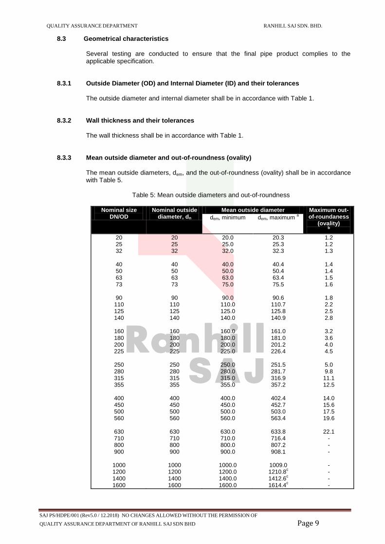
8.3 Geometrical characteristics
Several testing are conducted to ensure that the final pipe product complies to the applicable specification.
8.3.1 Outside Diameter (OD) and Internal Diameter (ID) and their tolerances The outside diameter and internal diameter shall be in accordance with Table 1. 8.3.2 Wall thickness and their tolerances The wall thickness shall be in accordance with Table 1.
8.3.3 Mean outside diameter and out-of-roundness (ovality)
The mean outside diameters, dem, and the out-of-roundness (ovality) shall be in accordance with Table 5.
Table 5: Mean outside diameters and out-of-roundness
Nominal size
DN/OD Nominal outside
diameter, dn Mean outside diameter Maximum out-
of-roundaness (ovality)
b
dem, minimum dem, maximum a
20 25 32
40 50 63 73
90
110 125 140
160 180 200 225
250 280 315 355
400 450 500 560
630 710 800 900
1000 1200 1400 1600
20 25 32
40 50 63 73
90
110 125 140
160 180 200 225
250 280 315 355
400 450 500 560
630 710 800 900
1000 1200 1400 1600
20.0 25.0 32.0
40.0 50.0 63.0 75.0
90.0
110.0 125.0 140.0
160.0 180.0 200.0 225.0
250.0 280.0 315.0 355.0
400.0 450.0 500.0 560.0
630.0 710.0 800.0 900.0
1000.0 1200.0 1400.0 1600.0
20.3 25.3 32.3
40.4 50.4 63.4 75.5
90.6
110.7 125.8 140.9
161.0 181.0 201.2 226.4
251.5 281.7 316.9 357.2
402.4 452.7 503.0 563.4
633.8 716.4 807.2 908.1
1009.0 1210.8
c
1412.6c
1614.4c
1.2 1.2 1.3
1.4 1.4 1.5 1.6
1.8 2.2 2.5 2.8
3.2 3.6 4.0 4.5
5.0 9.8
11.1 12.5
14.0 15.6 17.5 19.6
22.1
- - - - - - -

QUALITY ASSURANCE DEPARTMENT RANHILL SAJ SDN. BHD.
SAJ PS/HDPE/001 (Rev5.0 / 12.2018) NO CHANGES ALLOWED WITHOUT THE PERMISSION OF
QUALITY ASSURANCE DEPARTMENT OF RANHILL SAJ SDN BHD Page 10
Electro-fusion fittings
Butt-fusion fittings
9.0 MARKINGS OF PIPES The markings shall be marked at every 1m of the pipe. All pipes must be showing the markings at
least the following informations:
a) ‘HDPE’ letters b) Month and year of manufacture c) Brand d) Nominal diameter e) Minimum wall thickness f) The material grade (PE100) g) Nominal Pressure (PN) h) Standard reference i) Serial number j) Initial ‘SAJ’ in capital letter
10.0 PIPE FITTINGS 10.1 HDPE Fittings
HDPE fittings shall have a pressure rating equal to the pipe. Figure 3 shows the HDPE fittings used for electro-fusion and butt-fusion jointing method
Figure 3: HDPE Fittings
PN16

QUALITY ASSURANCE DEPARTMENT RANHILL SAJ SDN. BHD.
SAJ PS/HDPE/001 (Rev5.0 / 12.2018) NO CHANGES ALLOWED WITHOUT THE PERMISSION OF
QUALITY ASSURANCE DEPARTMENT OF RANHILL SAJ SDN BHD Page 11
10.2 Electro-fusion Fittings Electro-fusion fittings consists of straight coupler, reducing coupler, elbow/bend, transition adaptor, saddle and etc. Figure 4 below shows the various types of electro-fusion fittings that available for electro-fusion jointing method.
Figure 4: Electro-fusion fitting
10.3 Butt-fusion Fittings
Figure 5 shows the butt-fusion fittings available in market for butt-fusion jointing method.
Figure 5: Butt fusion fittings

QUALITY ASSURANCE DEPARTMENT RANHILL SAJ SDN. BHD.
SAJ PS/HDPE/001 (Rev5.0 / 12.2018) NO CHANGES ALLOWED WITHOUT THE PERMISSION OF
QUALITY ASSURANCE DEPARTMENT OF RANHILL SAJ SDN BHD Page 12
11.0 HDPE PIPE JOINTING 11.1 Electro-fusion Jointing
The effectiveness of electro-fusion jointing depends on attention to preparation of the jointing surfaces and the geometry of the assembly, in particular the removal of the oxidised surface of the pipe over the socket depth or saddle mounting area, ensuring the jointing surfaces are clean and free from contamination, and the assembly and clamping instructions are correctly followed.
A good practice of fusion preparation are as follows:
1. Rectangular cut of pipe ends 2. Roughly cleaning of jointing area 3. Marking of peeling area 4. Scrapping the fusion zone 5. Cleaning of prepared area 6. Marking of insertion depth 7. Mounting of components such as coupler and saddle 8. Fusion process 9. Cooling time 10. Records
11.1.1 Electro-fusion design requirements
The design of the heating coil zone has a direct impact on the quality of the connection. Table 7 shows the penetration depth and fusion zone length by according to each nominal diameter as tabulated in MS 1053: Part 3: 2006 and BS EN 12201.
Table 7: Electro fusion socket dimension
Nominal Diameter of the
Fitting, dn (mm) Penetration depth
(mm) Fusion zone length
(mm)
20 41 ≥ 10
25 41 ≥ 10
32 44 ≥ 10
40 49 ≥ 10
50 55 ≥ 10
63 63 ≥ 11
75 70 ≥ 12
90 79 ≥ 13
110 82 ≥ 15
125 87 ≥ 16
140 92 ≥ 18
160 98 ≥ 20
180 105 ≥ 21
200 112 ≥ 23
225 120 ≥ 26
250 129 ≥ 33
280 139 ≥ 35
315 150 ≥ 39
355 164 ≥ 42
400 179 ≥ 47
450 195 ≥ 51
500 212 ≥ 56
560 235 ≥ 61
630 255 ≥ 67
The longer the fusion zone, i.e. the area actually available for the homogenous material connection, the greater the processing safety in rough construction site conditions and by extension the long-term tightness of the pipe connection.

QUALITY ASSURANCE DEPARTMENT RANHILL SAJ SDN. BHD.
SAJ PS/HDPE/001 (Rev5.0 / 12.2018) NO CHANGES ALLOWED WITHOUT THE PERMISSION OF
QUALITY ASSURANCE DEPARTMENT OF RANHILL SAJ SDN BHD Page 13
11.2 Butt fusion Jointing
Butt fusion is a process of welding HDPE pipes and fittings using an electrically heated plate. It is suitable for jointing a straight pipe. However, only pipes and fittings of the same material type, size and rating shall be butt welded.
The process of butt fusion jointing are consists of:
a) Preparation of equipment b) Setting up c) Trimming d) Bead up e) Heat soak f) Plate removal g) Fusion jointing h) Cooling i) Debeading j) Records k) Maintenance, service and calibration
12.0 STORAGE
All materials should be carefully inspected at the time of delivery and any defective material set-aside before accepting the delivery into stores. The defective materials should be return to the suppliers immediately. Pipes and fittings should be used in the order of delivery to ensure the correct rotation of stock.
12.1 Storage at Depot for Pipes
All pipe stacks should be made on sufficiently firm, flat ground to support the weight of the pipes and any necessary lifting equipment. Stacking heights should be generally be kept to a minimum and adequate space allocated for lifting machinery to manoeuvre without causing accidental damage. For safety and convenience of handling the stacking height of bundles should not be more than 3m to prevent possible deformation of the pipes, bundles must be stored timber to timber as shown in Figure 6. At all times pipes should be stored away from exhaust outlets and all other high temperature sources. Care should be taken to avoid contact with lubricating or hydraulic oils, gasoline, solvents and other aggressive chemicals.
Figure 6: Bundlepacks storage

QUALITY ASSURANCE DEPARTMENT RANHILL SAJ SDN. BHD.
SAJ PS/HDPE/001 (Rev5.0 / 12.2018) NO CHANGES ALLOWED WITHOUT THE PERMISSION OF
QUALITY ASSURANCE DEPARTMENT OF RANHILL SAJ SDN BHD Page 14
For similar reasons, pipe coils should be stored flat and the number of coils per stack should be limited to:
7 coils for 20mm pipe
6 coils for 25mm pipe
5 coils for 32mm pipe
4 coils for 50mm pipe
3 coils for 63mm pipe
2 coils for 90mm pipe
Where the individual pipe lengths are stacked in pyramidal fashion, deformation may occur in the lower layers. Such stacks should therefore be not greater than 1m high as shown in Figure 7.
Figure 7: Individual pipe storage
12.2 Storage at Depot for Fittings
Electro-fusion fittings should be stored under cover, preferably on racking and in the manufacturer’s protective wrapping or cartons which should be kept intact until the fitting is required for use except spigot fittings. At all times fittings should be stored away from exhaust outlets and all other high temperature sources. Care should be taken to avoid contact with lubricating or hydraulic oils, gasoline, solvents and other aggressive chemicals.
12.3 Storage at Depot for Tools
All special tool and equipment associated with the jointing of pipes and fittings should be stored separately and securely until they are required for use.
12.4 Storage on Site
All pipe store locations should be on suitably firm, level ground, free from damaging material with adequate access for construction vehicles and/or lifting equipment.
In all storage sites, careful consideration should be given to the following aspects:
Security of all materials and equipment from theft, vandalism, accidental damage or contamination.
Safety of pedestrians.
The movement of traffic and construction equipment.
Pipes exposed to hot temperature for a long period (more than one month) should be cover by canvas as pipe protection and it need to be end capped to make sure there is no rubbish, soils or etc. remain in the pipe. The end caps can only be removed when the jointing will be done.

QUALITY ASSURANCE DEPARTMENT RANHILL SAJ SDN. BHD.
SAJ PS/HDPE/001 (Rev5.0 / 12.2018) NO CHANGES ALLOWED WITHOUT THE PERMISSION OF
QUALITY ASSURANCE DEPARTMENT OF RANHILL SAJ SDN BHD Page 15
When stringing is adopted, pipes should be placed well clear of the excavators and away from excavated material area. They should be wedged to prevent accidental movement. Where necessary protective barriers complete with adequate warning signs and lights should be erected.
13.0 PRE-DELIVERY INSPECTION AND EVALUATION
13.1 It is the responsibility of the tenderer to inform SAJ for inspection purposes during manufacturing and before delivery.
13.2 SAJ reserve the right to inspect and witness the testing of product offered. 13.3 At any time, when requested, the supplier is to provide SAJ a sample of the product offered
for evaluation purposes. All costs shall be borne by the supplier.
13.4 If at any time the supplier fails to deliver the required sample, the product is deemed fail to meet the specifications.
14.0 CERTIFICATION 14.1 Manufacturer or supplier are required to provide a copy of raw material approval certificate
to SAJ. 14.2 Manufacturer or supplier are required to provide a copy of mill certificate for each batch of
pipes to SAJ. 14.3 Manufacturer of supplier are required to provide a copy of the certificate and testing report
from SIRIM, IKRAM or other recognized certification body to SAJ. 14.4 Manufacturer or supplier are required to provide a copy of SPAN’s registration certificate for
each product to be supplied separately. (i.e. pipes and fittings) to SAJ.
14.5 SAJ have the right to refuse offer or reject supply if the documents required are not enclosed.


