
Evaluates: MAX32650–MAX32652MAX32650 Evaluation Kit
General DescriptionThe MAX32650 EV kit provides a platform for evaluating the capabilities of the MAX32650 ultra-low power memory-scalable microcontroller designed specifically for high per-formance battery powered applications.
EV Kit Contents ● MAX32650 EV kit containing a MAX32650 with a
preprogrammed demo ● JTAG debugger with ribbon cable ● Two standard A to Micro B USB cables
Benefits and Features ● 3.5in 320 x 240 Color TFT Display ● 64MB HyperRAM ● 64MB XIP Flash ● 1MB XIP RAM ● USB 2.0 Micro B Interface ● USB 2.0 Micro B to Serial UARTs
• Selection with Jumpers Between UART0 and UART2
● Micro SD Card Interface ● Select GPIOs Accessed through 0.1in Header ● Access to the Four Analog Input Through 0.1in
Header ● Arm® or SWD JTAG 20-Pin Header ● On-Board PMIC to Source Power for the MAX32650 ● Board Power Provided by Either USB Port ● Individual Power Measurement on All IC Rails
Through Jumpers ● On-Board 1.8V and 3.3V Regulators for Peripherals ● Two General-Purpose LEDs and Two General-
Purpose Pushbutton Switches
319-100097; Rev 3; 3/18
Arm is a registered trademark of Arm Limited (or its subsidiaries) in the US and/or elsewhere.
#Denotes RoHS compliant.
Ordering InformationPART TYPE
MAX32650-EVKIT# EV Kit

Maxim Integrated │ 2www.maximintegrated.com
Evaluates: MAX32650–MAX32652MAX32650 Evaluation Kit
MAX32650 EV Kit Board

Maxim Integrated │ 3www.maximintegrated.com
Evaluates: MAX32650–MAX32652MAX32650 Evaluation Kit
Windows is a registered trademark and registered service mark of Microsoft Corporation.
Quick StartProcedureFollow the steps below to verify board operation:1) While observing safe ESD practices, carefully remove
the MAX32650 EV kit board out of its packaging. Quickly inspect the board to ensure that no damage occurred during shipment. Jumpers/shunts are pre-installed prior to testing and packaging.
2) The MAX32650 is preprogrammed with a demo program. To power up the board and run the demo. Verify that the board is powered up by observing that the blue LED (DS3) and the green LEDs (DS1 and DS2) are illuminated.
3) Once power is applied, the demo initiates and displays the Maxim logo upon successful completion.
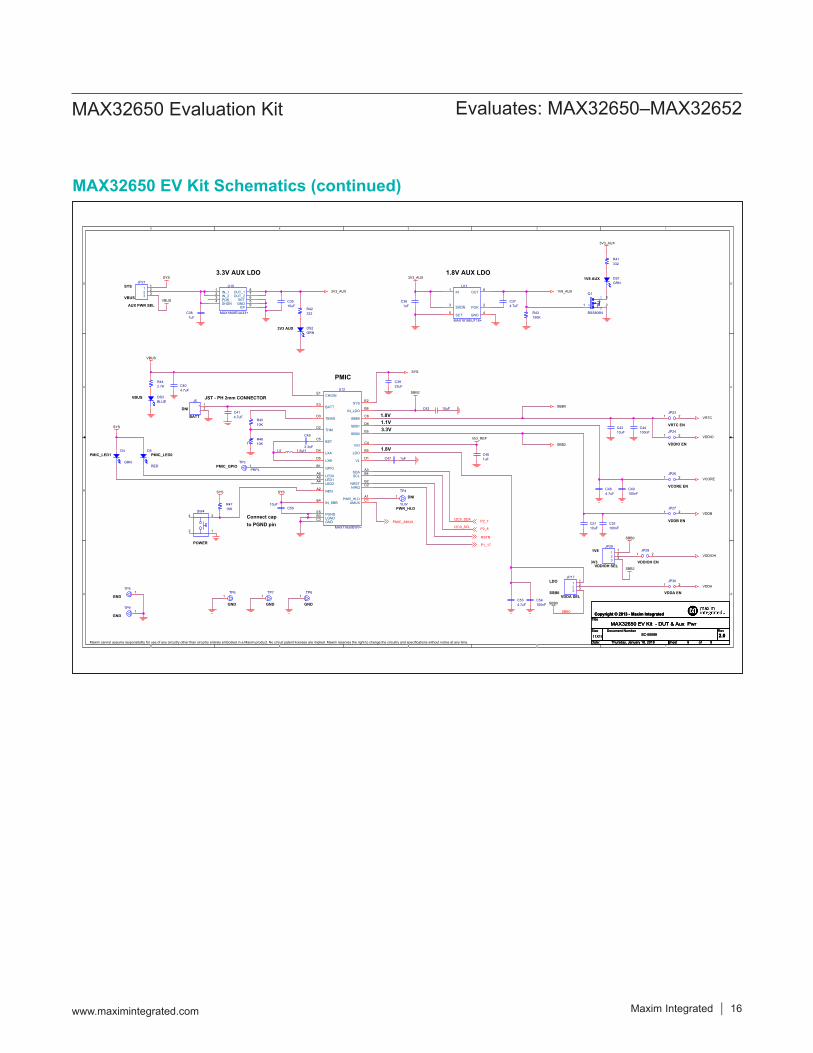
Detailed Description of HardwarePower SupplyThe EV kit is powered by +5V and is made available through VBUS on the Micro-USB type-B connectors CN1 or CN2. This sources the MAX77650 PMIC that provides power to the MAX32650 rails. The board is default jum-pered for power provided by CN1. A blue LED (DS3) illuminates when the board is powered. Green LEDs DS1 and DS2 illuminate when the 1V8 and 3V3 LDOs are powered, respectively. These are dedicated for sourcing power to the board peripherals.
Current MonitoringJumpers provide convenient current monitoring points for VRTC (J6), VDDIO (J7), VDDIOH (J8 or J11), VCORE (J9), VDDB (J10) and VDDA (J12).
ClockingThe IC nominally operates from an internal oscillator of 120MHz. Three other lower frequency oscillators can be selected depending on power needs. There is an internal 32.768 oscillator that requires an external 32.768kHz crystal (Y1), for accurate RTC timekeeping and USB operation.
Color TFT DisplayThe display provided is a 3.5in 320 x 240 color TFT. It has three-wire serial control, a 24-bit parallel RGB interface with a white LED backlight.
Universal Serial BusA USB Micro B connector (CN1) is provided for proto-typing USB slave applications. The USB 2.0 full-speed interface (480Mbps) transceiver is embedded in the MAX32650.
UART InterfacesThe EV kit provides a USB-to-UART bridge chip, FTDI FT230X. This bridge eliminates the requirement for a physical RS-232 COM port. Instead, the IC’s UART access is through the Micro-USB type-B connector, CN2. The USB-to-UART bridge can be connected to UART 0 or UART 2 of the IC with jumpers JP12 (RX), JP13 (TX), JP15 (CTS), and JP16 (RTS). Virtual COM port drivers and guides for installing Windows® drivers are available at the FTDI chip website.

Maxim Integrated │ 4www.maximintegrated.com
Evaluates: MAX32650–MAX32652MAX32650 Evaluation Kit
Arm JTAG ConnectorsThe Arm standard 20-pin connector pinout is provided by shrouded header J4. JH6 is provided as an optional debugging access point, it is not populated by default. The JTAG debugger is supplied with the EV kit. JTAG logic levels are fixed to VDDIO (1.8V).
JTAG Serial Wire Debug (SWD) SupportSWD is supported by the IC and this EV kit. The port shares its clock (SWCLK) with JTAG TCK and a bidirec-tional data pin (SWDIO) is shared with JTAG TMS.
Reset PushbuttonPushbutton SW3 manually resets the MAX32650.
Indicator LEDsThe indicator LEDs D1 (red) and D2 (green) are connect-ed to GPIO P2.25 and P2.26, respectively. The GPIOs need to be configured for 3.3V or open drain since they are sourced at 3.3V.
GPIO PushbuttonsThe two pushbuttons (SW2 and SW3) are connected to GPIO P2.28 and P2.30, respectively. If the pushbutton is pressed, the attached port pin is pulled low.
GPIO HeadersSelect GPIOs are accessible through a 0.1in spaced header pins. The IC provides support for both 1.8V and 3.3V peripherals through power rails VDDIO and VDDIOH. GPIO voltages can be programmed on pin-by-pin basis. Refer to the IC’s operating guide for more detail.
VIO_REF SettingThe VIO_REF voltage is set by jumper JP14 and was originally selectable between VDDIO and VDDIOH. This, however, can place 3.3V on the pullup (R1) on RSTN and cause an extra ~2μA of current to be driven in RSTN. To prevent this, JP14 position 3 has been clipped and VIO_REF jumpered to VDDIO.
Table 1. Jumper Settings
*Denotes default setting.
JUMPER SIGNAL SETTINGS DESCRIPTION
JP1 32KIN1-2* Connects 32KIN to the 32.768kHz crystal
Open Disconnects 32KIN to the 32.768kHz crystal
JP2 AIN31-2 Connects analog header TP1 to AIN32-3 Connects PMIC_AMUX TP1 to AIN3
JP3 P2_81-2* Connects 1.8V pullup to P2_82-3* Connects 3.3V pullup to P2_8
JP4 P2.171-2 Connects 1.8V pullup to P2.172-3 Connects 3.3V pullup to P2.17
JP5 P2.181-2 Connects 1.8V pullup to P2.182-3 Connects 3.3V pullup to P2.18
JP6 P2.71-2 Connects 1.8V pullup to P2.72-3 Connects 3.3V pullup to P2.7

Maxim Integrated │ 5www.maximintegrated.com
Evaluates: MAX32650–MAX32652MAX32650 Evaluation Kit
Table 1. Jumper Settings (continued)
*Denotes default setting.
JUMPER SIGNAL SETTINGS DESCRIPTION
JP7 P2.251-2* Connects LED D1 to P2.25
Open Disconnects LED D1 to P2.25
JP8 P2.261-2* Connects LED D2 to P2.26
Open Connects LED D2 to P2.26
JP9 RAM XIP VCC1-2* Connects 1V8_AUX to RAM XIP VCC
Open Disconnects 1V8_AUX to RAM XIP VCC
JP10 FLASH XIP VCC 1-2* Connects 1V8_AUX to FLASH XIP VCCOpen Disconnects 1V8_AUX to FLASH XIP VCC
JP11 VBUS 1-2 Connects USB port to VBUS2-3* Connects USB-UART port to VBUS
JP12 TXD of USB-Serial IC 1-2* Connects TXD of USB-Serial IC to P2.11 (UART0_RX)2-3 Connects TXD of USB-Serial IC to P2.1 (UART2_RX)
JP13 RXD of USB-Serial IC 1-2* Connects RXD of USB-Serial IC to P2.12 (UART0_TX)2-3 Connects RXD of USB-Serial IC to P1.10 (UART2_TX)
JP14 VIO_REF 1-2* Connects VDDIO to VIO_REF2-3 Connects VDDIOH to VIO_REF
JP15 RTS of USB-Serial IC1-2* Connects RTS of USB-Serial IC to P2.9 (UART0_CTS0)2-3 Connects RTS of USB-Serial IC to P1.7 (UART2_CTS2)
JP16 CTS of USB-Serial IC1-2* Connects CTS of USB-Serial IC to P2.10 (UART0_RTS0)2-3 Connects CTS of USB-Serial IC to P1.8 (UART2_RTS2)
JP17 VDDA1-2 Connects VDDA to LDO of the PMIC2-3* Connects VDDA to SSB0 of the PMIC
JP18 TXD of USB-Serial IC1-2* Connects TXD of USB-Serial IC to JP12 RX SEL jumper
Open Disconnects TXD of USB-Serial IC to JP12 RX SEL Jumper
JP19 RXD of USB-Serial IC1-2* Connects RXD of USB-Serial IC to JP13 TX SEL Jumper
Open Disconnects RXD of USB-Serial IC to JP13 TX SEL Jumper
JP20 HyperRAM VCC1-2* Connects 1V8_AUX to VCC Hyper RAM VCC
Open Disconnects 1V8_AUX to VCC Hyper RAM VCC
JP21 3V3 LDO VCC1-2* Connects PMIC SYS to 3V3 LDO
Open Connects VBUS to 3V3 LDO
JP22 HyperRAM VCCQ1-2* Connects 1V8_AUX to VCC Hyper RAM VCCQ
Open Disconnects 1V8_AUX to VCC Hyper RAM VCCQ
JP23 VRTC1-2* Connects PMIC SBB0 to VRTC
Open Disconnects PMIC SBB0 to VRTC
JP24 VDDIO1-2* Connects PMIC SBB0 to VDDIO
Open Disconnects PMIC SBB0 to VDDIO

Maxim Integrated │ 6www.maximintegrated.com
Evaluates: MAX32650–MAX32652MAX32650 Evaluation Kit
Table 1. Jumper Settings (continued)
*Denotes default setting.
JUMPER SIGNAL SETTINGS DESCRIPTION
JP25 N/AN/A Jumper not presentN/A Jumper not present
JP26 VCORE1-2* Connects PMIC SBB1 to VCORE
Open Disconnects PMIC SBB1 to VCORE
JP27 VDDB1-2* Connects PMIC SBB2 to VDDB
Open Disconnects PMIC SBB2 to VDDB
JP28 VDDIOH1-2* Connects PMIC power to VDDIOH
Open Disconnects PMIC power to VDDIOH
JP29 VDDIOH1-2* Connects PMIC SBB0 (1.8V) to VDDIOH2-3 Disconnects PMIC SBB2 (3.3V) to VDDIOH
JP30 VDDA1-2* Connects PMIC power (LDO or SSB0) to VDDA
Open Disconnects PMIC power (LDO or SSB0) to VDDA

Maxim Integrated │ 7www.maximintegrated.com
Evaluates: MAX32650–MAX32652MAX32650 Evaluation Kit
MAX32650 EV Kit Bill of MaterialsQty Part Reference Value BOM Description Manufacturer PN Manufacturer
8 C1,C3,C4,C6,C7,C8,C46,C47 1uF CAP CER 1UF 6.3V X5R 0402 GRM155R60J105KE19D Murata4 C2,C5,C9,C10 150pF CAP CER 150PF 50V 5% C0G 0603 C1608C0G1H151J080AA TDK Corporation5 C11,C30,C37,C40,C41 4.7uF CAP CER 4.7uF 10V 10% X5R 0603 C0603C475K8PACTU Kemet6 C12,C14,C20,C21,C36,C38 1uF CAP CER 1uF 16V 10% X7R 0603 GCM188R71C105KA64D Murata1 C13 10pF CAP CER 10pF 50V 5% NP0 0603 06035A100JAT2A AUX
14 C15,C16,C17,C18,C19,C22,C23, C26,C31,C34,C44,C49,C52,C54
100nF CAP CER 0.1UF 10V 10% X5R 0402 GRM155R61A104KA01D Murata
2 C24,C32 100nF CAP CER 0.1UF 25V 10% X8R 0603 C1608X8R1E104K080AA TDK Corporation1 C25 1uF CAP CER 1UF 35V 10% X5R 0603 GMK107BJ105KA-T Taiyo Yuden1 C27 10nF CAP CER 10nF 25V 10% X7R 0603 GRM188R71E103KA01D Murata2 C28,C29 47pF CAP CER 47PF 50V 1% NP0 0402 C1005C0G1H470F050BA TDK Corporation1 C33 100nF CAP CER 0.1uF 16V 10% X7R 0603 C0603C104K4RACTU Kemet1 C35 10uF CAP CER 10uF 10V 10% X7R 0805 GRM21BR71A106KE51L Murata1 C39 22uF CAP CER 22UF 4V 20% X5R 0603 AMK107BJ226MA-T Taiyo Yuden4 C42,C43,C50,C51 10uF CAP CER 10UF 6.3V 20% X5R 0402 GRJ155R60J106ME11D Murata Electronics1 C45 3.3nF CAP CER 3300PF 16V 10% X7R 0402 GRM15XR71C332KA86D Murata Electronics2 C48,C53 4.7uF CAP CER 4.7UF 4V 20% X5R 0402 AMK105BJ475MV-F Taiyo Yuden1 CN1, CN2 MICRO USB B R/A CONN RCPT 5POS MICRO USB B R/A 47346-0001 Molex2 D1,D5 RED LED 660NM RED WTR CLR 1206 SMD SML-LX1206SRC-TR Lumex Opto4 D2,D4,DS1,DS2 GRN LED 565NM WTR CLR GREEN 1206 SMD SML-LX1206GC-TR Lumex Opto1 D3 CMOSH-3 Schottky Diode 30V_100mA CMOSH-3 Central Semiconductor1 DS3 BLUE LED 469NM BLUE DIFF 1206 SMD HSMR-C150 Avago Technologies US Inc.4 H1,H2,H3,H4 DNI DNI MTG 125DRL 300PAD1 J1 047571-0001 CONN MICRO SD CARD PUSH-PULL R/A 047571-0001 Molex1 J2 54P 0.5mm CONN FFC/FPC 54POS ZIF .5MM SMD 512965494 Molex Inc1 J3 10P CORTEX DEBUG CONN HEADER 10POS DUAL .05" SMD FTSH-105-01-F-DV-K Samtec1 J4 20P 10x2 CONN HEADER 2.54MM 20POS GOLD SBH11-PBPC-D10-ST-BK Sullins1 J5 2POS 2MM CONN HEADER PH TOP 2POS 2MM B2B-PH-K-S(LF)(SN) JST Sales America Inc
15JP1,JP7,JP8,JP9,JP10,JP18,
JP19,JP20, JP22, JP23, JP24, JP26, JP27, JP28, JP30
JUMPER CONN HEADER .100 SINGL STR 2POS PEC02SAAN Sullins
1 JH1 4P 1x4 CONN HEADER .100 SINGL STR 4POS PEC04SAAN Sullins3 JH2,JH3,JH4 18P 2x9 CONN HEADER .100 DUAL STR 18POS PEC09DAAN Sullins1 JH5 20P 2x10 CONN HEADER .100 DUAL STR 20POS PEC10DAAN Sullins1 JH6 6P 1x6 CONN HEADER .100 SINGL STR 6POS PEC06SAAN Sullins1 JH7 5P 1x5 CONN HEADER .100 SINGL STR 5POS PEC05SAAN Sullins
14JP2,JP3,JP4,JP5,JP6,JP11,JP12,
JP13,JP14,JP15,JP16,JP17, JP21, JP29
3P 3x1 CONN HEADER .100 SINGL STR 3POS PEC03SAAN Sullins
1 L1 22uH INDUCTOR POWER 22UH 20% SMD CLF6045T-220M TDK Corporation2 L2,L4 HZ1206C202R-10 FERRITE CHIP SIGNAL 2000 OHM SMD HZ1206C202R-10 Laird-Signal Integrity Products1 L3 BLM21PG221SN1D FERRITE CHIP 220 OHM 0805 BLM21PG221SN1D Murata Electronics 1 L5 1.5uH Fixed Inductors 0806 1.5uH 20% 1.5A DFE201610E-1R5M=P2 Murata Electronics 1 PCB1 PCB

Maxim Integrated │ 8www.maximintegrated.com
Evaluates: MAX32650–MAX32652MAX32650 Evaluation Kit
MAX32650 EV Kit Bill of Materials (continued)Qty Part Reference Value BOM Description Manufacturer PN Manufacturer
1 Q1 BSS806N MOSFET N-CH 20V 2.3A SOT23 BSS806N H6327 Infineon Technologies
13 R1,R12,R13,R14,R15,R16,R17, R25,R28,R31,R32,R39,R47 10K RES 10K OHM 1/10W 1% 0603 SMD ERJ-3EKF1002V Panasonic
4 R2,R4,R6,R8 33.2 RES 33.2 OHM 1/10W 1% 0603 SMD ERJ-3EKF33R2V Panasonic4 R3,R5,R7,R9 49.9 RES 49.9 OHM 1/10W 1% 0603 SMD ERJ-3EKF49R9V Panasonic5 R10,R11,R18,R19,R45 10K RES 10K OHM 1/10W 1% 0402 SMD ERJ-2RKF1002X Panasonic2 R20,R21 100 RES 100 OHM 1/10W 1% 0603 SMD ERJ-3EKF1000V Panasonic1 R22 470 RES 470 OHM 1/10W 1% 0603 SMD ERJ-3EKF4700V Panasonic3 R23,R41,R42 332 RES 332 OHM 1/10W 1% 0603 SMD ERJ-3EKF3320V Panasonic1 R24 137K RES SMD 137K OHM 1% 1/10W 0603 ERJ-3EKF1373V Panasonic1 R26 10K RES 10K OHM 1/10W 1% 0603 SMD ERJ-3EKF1002V Panasonic1 R27 1M RES SMD 1M OHM 5% 1/8W 0805 ERJ-6GEYJ105V Panasonic2 R29,R30 27 RES 27 OHM 1/10W 1% 0603 SMD ERJ-3EKF27R0V Panasonic5 R35,R36,R37,R38,R40 DNI DNI 04021 R43 150K RES 150K OHM 1/10W 1% 0603 SMD ERJ-3EKF1503V Panasonic1 R44 2.7K RES 2.7K OHM 1/10W 1% 0603 SMD ERJ-3EKF2701V Panasonic1 R46 10K NTC THERMISTOR 10K OHM 1% 0402 NCP15XH103F03RC Murata Electronics2 SW1,SW4 B3S-1002 BY OMZ SWITCH TACTILE SPST-NO 0.05A 24V B3S-1002 BY OMZ Omron Electronics2 SW2,SW3 B3S-1000 SWITCH TACTILE SPST-NO 0.05A 24V B3S-1000 Omron Electronics1 TP1 6P 1x6 CONN HEADER .100 SINGL STR 6POS PEC06SAAN Sullins1 TP2 YLW TEST POINT PC MULTI PURPOSE YEL 5014 Keystone Electronics1 TP3 PRPL TEST POINT PC MULTI PURPOSE PRPL 5129 Keystone Electronics1 TP4 YLW TEST POINT PC MULTI PURPOSE YEL 5014 Keystone Electronics2 TP5,TP9 1P CONN HEADER .100 SINGL STR 1POS PEC01SAAN Sullins3 TP6,TP7,TP8 BLK TEST POINT PC COMPACT .063"D BLK 5006 Keystone Electronics1 U1 MAX32650ICE+ MAX32650ICE+ 144P TQFP MAX32650ICE+ Maxim Integrated1 U2 MAX8574EUT+T IC CONV LCD BOOST SOT23-6 MAX8574EUT+T Maxim Integrated1 U3 NHD-3.5-320240MF-ATXL#-1 LCD DISP TFT 3.5" 320X240 B/L NHD-3.5-320240MF-ATXL#-1 Newhaven Display Intl1 U4 MX25U6435FM2I-10G IC FLASH 64MBIT 104MHZ 8SOP MX25U6435FM2I-10G Macronix1 U5 N01S818HAT22I IC SRAM 1MBIT 20MHZ 8TSSOP N01S818HAT22I ON Semiconductor1 U6 S27KS0641DPBHV020 IC HYPERRAM 64Mb 24BGA 166MHz Cypress Semiconductor2 U7,U9 MAX3207EAUT+T ESD PROT DIFF SOT23-6 MAX3207EAUT+T Maxim Integrated1 U8 FT230XS-R IC USB SERIAL BASIC UART 16SSOP FT230XS-R FTDI1 U10 MAX1806EUA33+ IC REG LDO 3.3V/ADJ 0.5A 8UMAX MAX1806EUA33+ Maxim Integrated1 U11 MAX1818EUT18+ IC REG LDO 1.8V/ADJ 0.5A SOT23-6 MAX1818EUT18+ Maxim Integrated1 U12 MAX77650 max77650 PMIC MAX77650 Maxim Integrated1 Y1 32.768kHz CRYSTAL 32.768KHZ 6.0PF SMD ABS07-32.768KHZ-6-T Abracon Corp
Maxim Integrated │ 9www.maximintegrated.com
Evaluates: MAX32650–MAX32652MAX32650 Evaluation Kit
MAX32650 EV Kit Schematics

Maxim Integrated │ 10www.maximintegrated.com
Evaluates: MAX32650–MAX32652MAX32650 Evaluation Kit
MAX32650 EV Kit Schematics (continued)
PORT 0 PORT 1 PORT 2 PORT 2 & 3
P0.[15:13]
P0.[31:16]
P1.[31:22, 10:7, 2]P1.[15:0]
32.768 kHz
32KIN 32KOUT
MAX32650
/CSDI(IO0)D0(IO1)/WP(IO2)/HOLD(IO3)SCLKM25U6435FM2I
PORT 0
P2.[30, 28, 26:23, 18:16]
CLCD_HSYNCCLCD_GRN[7:0]
P1.[29:23], P0.258CLCD_BLU[7:0]
P1.[31,30,18:13]8CLCD_RED[7:0]
4
MOLEX 54 PIN .5MMNEWHAVEN TFT DISPLAY
8
320 x 240 PIXELS3.5" DIAGONAL
NHD-3.5-320240MF-ATXLBACKLIGHT
PWR
P0.[20:13]
CLCD_VSYNCCLCD_CLK
P0.24P2.6
P0.23P2.23 RESET
/CSP0.29
MAX8574
SCKP3.4SDIP3.7
USBCN1
MAX3207ESDTVS
2
USBMICRO B
RX SEL
FT230X
TX
TX SELRX
ESDTVS
VBUS
VCC
RX0
RX2
TX0
TX2
RTS_N SEL
RTS_NCTS_N SEL
CTS_N
CTS0_N
P2.11
P1.9
P2.12
P1.10
CTS2_N
RTS0_N
RTS2_N
P2.9
P1.7
P2.10
P1.8
USB
MAX3207
CN2USB/PWR - UARTS
USB/PWR
VIO_REF
3V3VCCIO
USB COMMUNICATIONS
VIO_REF
VIO_REF
P0.26P0.28P0.29P0.27
TDITMSTCKTDO
JTAG/SWD
FLASH XIPP0.7
P0.10P0.9
P0.11P0.12P0.8
/CSDI(IO0)D0(IO1)/WP(IO2)/HOLD(IO3)SCLKN01S818HAT221
RAM XIPP0.6P0.1P0.2P0.5P0.4P0.3
VDDA
CHGINVRTC
MAX77650
RSTN
RSTN
SYS
SDASCL
VBUS
SYS
TBIAS
THMDNI
VRTC EN
PMIC_LED0
RESET
I2C0_SDAI2C0_SCL
USBMICRO B
NRST
NIRQ
PWR_HLD
VDDIO ENVDDIO
VCORE ENVCORE
VDDBVDDB EN
VDDA EN
PMIC_AMUX
S27KS0641DPBH
HyperRAM
HYP_DQ[7:0]
HYP_CLKHYP_CLKN
HYP_RWDS
HYP_CS0HYP_CS1P3.0
P1.11
P1.12, 13, 15, 16, 19, 20:21P1.14
1V8_AUX
HYP VCC ENVCC
1V8_AUX
HYP VCCQ ENVCCQ
HYP_RST_NHYP_RFU2HYP_RFU3HYP_RFU4HYP_RFU5
HYP
SYS
PMIC_LED1
SYS
SBB0BUCK/BOOST 1
SBB1BUCK/BOOST 2
SBB2BUCK/BOOST
LDO IN_LDO
SBB0
SBBO
VDDA SEL
IN_SBBSYS
NENPOWER
GPIO
RX EN
TX EN
RSTN
VIO_REF
ANALOG FRONT END
AIN0AIN1AIN2AIN3
OptionalFilter
AIN3 SEL
ANALOGCORTEX
ARM
PMIC_AMUX FROM PMIC
TO ANALOG
VBUS SEL
P2_17 PU1V8_AUX
3V3_AUX
P2_18 PU1V8_AUX
3V3_AUX
P2_7 PU1V8_AUX
3V3_AUX
P2_8 PU1V8_AUX
3V3_AUX
3.3V LDO
AUX_PWR_SELSYS
MAX1806
3V3_AUX
1.8V LDO
MAX1806
1V8_AUX
3V3_AUX3V3_AUX
1.8V
1.1V
3.3V
1.8V
P2.7P2.8P1.17
JST-PH connector
DNI
SBB2
VDDIOHVDDIOH EN
VDDIOH SELSBBO
SBB2

Maxim Integrated │ 11www.maximintegrated.com
Evaluates: MAX32650–MAX32652MAX32650 Evaluation Kit
MAX32650 EV Kit Schematics (continued)

Maxim Integrated │ 12www.maximintegrated.com
Evaluates: MAX32650–MAX32652MAX32650 Evaluation Kit
MAX32650 EV Kit Schematics (continued)

Maxim Integrated │ 13www.maximintegrated.com
Evaluates: MAX32650–MAX32652MAX32650 Evaluation Kit
MAX32650 EV Kit Schematics (continued)

Maxim Integrated │ 14www.maximintegrated.com
Evaluates: MAX32650–MAX32652MAX32650 Evaluation Kit
MAX32650 EV Kit Schematics (continued)

Maxim Integrated │ 15www.maximintegrated.com
Evaluates: MAX32650–MAX32652MAX32650 Evaluation Kit
MAX32650 EV Kit Schematics (continued)
Components inside dashed box should be placed as close to the USB-UART connector as practical.
Maxim Integrated │ 16www.maximintegrated.com
Evaluates: MAX32650–MAX32652MAX32650 Evaluation Kit
MAX32650 EV Kit Schematics (continued)

Maxim Integrated cannot assume responsibility for use of any circuitry other than circuitry entirely embodied in a Maxim Integrated product. No circuit patent licenses are implied. Maxim Integrated reserves the right to change the circuitry and specifications without notice at any time.
Maxim Integrated and the Maxim Integrated logo are trademarks of Maxim Integrated Products, Inc. © 2018 Maxim Integrated Products, Inc. │ 17
Evaluates: MAX32650–MAX32652MAX32650 Evaluation Kit
Revision HistoryREVISIONNUMBER
REVISIONDATE DESCRIPTION PAGES
CHANGED
0 10/17 Initial release —
1 1/18 Updated MAX32650 EV Kit Board Photo, Procedure, Arm JTAG Connectors, Table 1, and MAX32650 EV Kit Bill of Materials, and added VIO_REF Settings 2–7
2 2/18 Added MAX32651 and MAX32652 to data sheet, updated schematics 1–173 3/18 Updated orderable part number 1
For pricing, delivery, and ordering information, please contact Maxim Direct at 1-888-629-4642, or visit Maxim Integrated’s website at www.maximintegrated.com.


