
User handbook
from the version 02.07
AR
DE
TEM
- TA
CO
/148
-B 0
3/17
Any
dat
a in
this
doc
umen
tatio
n m
ay b
e m
odifi
ed w
ithou
t prio
r not
ice.
ÉTUDES ET RÉALISATIONS ÉLECTRONIQUES / INSTRUMENTATIONS / AUTOMATISME
Route de Brindas - Parc d’activité d’Arbora - N°269510 - Soucieu en Jarrest
FRANCE
Tél. 04 72 31 31 30 - Fax 04 72 31 31 31Tel. Intern. 33 4 72 31 31 30 - Fax Intern. 33 4 72 31 31 31
http: //www.ardetem.com - e-mail: [email protected]
MEASURE CONCENTRATOR FOR TPIs
TPIv M TPIv ME TPIv MP TPIv MPB TPIv MEE, ER TPIv MEER

p1
Summary
UE conformity declaration p2
1 . INTRODUCTION p3
1.1 General features p3 1.2 Communication interfaces p3 • Digital data link RS485 2 wire p3 • Ethernet p3 • Profinet p3 • Profibus p3 • USB p3 1.3 Functions p4 • Supply controller for TPIs p4 • 2 alarm outputs of the type «potential free contact» p4 • 2 isolated logic inputs p4 • Supervisor and concentrator of measures for TPIs p4
1.4 Available options p5
2 . DIMENSIONS - CONNECTIONS p5
3 . CONFIGURATION OF A LOCAL NETWORK OF TPIs p8
4 . ANNEXE: MODBUS p9
4.1 Table of the MODBUS addresses p11 4.2 Description of the born MODBUS functions p12
Summary
4.3 Reading in double integer format p12
4.4 CRC16 calculation algorythm p13
5. ANNEXE MODBUS TCP (TPIv ME) p14
6. ANNEXE PROFINET p14
7. ANNEXE DATALOGGER (OPTION D) p15
8. ANNEXE TPIvMEE/TPIvMER TPIvMEEM/TPIvMERM p15
9. ANNEXE CALCULATIONS (OPTION C) p16
10. ANNEXE PROFIBUS p16

p2
UE CONFORMITY DECLARATION
The manufacturer: ARDETEM-SFERE Route de Brindas Parc d’activité d’Arbora n°2 69510 Soucieu en Jarrest France
declares that the following products: Name: Measure concentrator Type: TPIv M TPIv ME TPIv MP TPIv MPB TPIv MEE, ER TPIv MEERcomply with the following directives and standards:
The EMC Directive 2014/30/UE EN 61326-1 : 2013
The Low Voltage Directive 2014/35/UE EN 61010-1 : 2011
The ATEX directive 2014/34/UE EN 60079-0 : 2011 EN 60079-15 : 2010
Soucieu en Jarrest, February 14, 2017
Jacques Huguet Signature of the Manager
This appliance has to be installed in an environment defined in pollution degree 2 / Overvoltage category II or better for a max. altitude of 2000 m.
Before any installation or maintenance work, make sure the power supply of the instrument is cut.
This symbole indicates that the module is protected by a double or reinforced isolation.
When the instrument is permanently connected to a dangerous voltage, it is necessary to add a means of sectionalizing on the power supply (switch, fuse or circuit breaker) near to the product, to make it easy of access and to mark it as being the means for cutting the instrument.
This sectionalizing means should cut all the conductors leading the cur-rent.
The person who has designed the system (electrical installation including the instrument) is sole responsable for the safety and must make sure it has been designed according to the current safety standards.
This appliance contains electronic components and should not be disposed of with the domestic waste.It should be collected with the WEEE (Waste Elec-trical and Electronic Equipment), according to the current regulation.
The instrument may be connected to dangerous electrical voltages.It must be mounted, connected and implemented respecting the current specific regulations, by a qualified technician, trai-ned to the safety regulations, who will have read this manual.

p3
1. INTRODUCTION• The TPIv M is a supply controller module and concentrator of measures for
the converters or modules of the series TPIs.
• It allows configurating and supervising the measures and the «inputs / out-puts» of a local network consisting of TPIs’s.
• The programming is performed with a PC via the µUSB access.
• The supervision is done via the access by RS485 or Ethernet / Internet (if TPIv ME) or Profinet (if TPIv MP), or Profibus (if TPIv MPB).
1.1 General features
Operating temperature ........................ -25°C to +70°C (-20°C to +50°C if option D)
Storage temperature ........................... -40°C to +85°C (-20°C to +65°C if option D)
Supply ................................................. 16.8 to 31.2 Vdc
Max. power draw ................................. 2W (TPIv ME)............................................................. 2.5W (TPIv MPB)............................................................. 3W (TPIv MP)Max. supply current of the Bus............ 5Adc
Galvanic partition..........................2.5kV-50Hz-1mn between: - supplies - communication with TPIs, - alarm relay output n°1, - alarm relay output n°2, - programming access (µUSB or RS485 or Ethernet or Profinet, or Profibus), - logic input n°1, - logic input n°2.
1.2 Communication interfaces
• Digital data link RS485 2 wire
Protocoles Modbus-JbusFormat of the data: integer and double integerExclusive transmission format: 1 start bit, 8 parityless data bits,1 stop bitSlave number between 1 and 255Baud rate between 1200 and 19200 BaudsOptional time delay before the response of 50ms.
Table of the Modbus addresses and the used functions: see annexe page 9
• Ethernet (TPIv M-E)
RJ45 type female footingSpeed = 10/100 Mbauds
• USB
USB male footingVersion 2.0
• Profinet (TPIv MP)
RJ45 type female footing
Installation in ATEX area 2
Marking:
II 3 G Ex nA IIC T4 Gc
Compliance with standards:
Electrical safety ............................ EN 61010-1
ATEX 2014/34/UE ........................ EN 60079-0, EN 60079-15
Directive EMC 2014/30/UE .......... EN 61326-1
• Profibus (TPIv MPB)
DB9 type female footingMax. speed = 12 Mbauds
p4
1.3 Functions
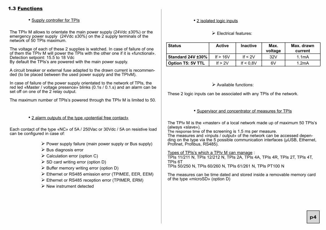
• Supply controller for TPIs
The TPIv M allows to orientate the main power supply (24Vdc ±30%) or the emergency power supply (24Vdc ±30%) on the 2 supply terminals of the network of 50 TPIs maximum.
The voltage of each of these 2 supplies is watched. In case of failure of one of them the TPIv M will power the TPIs with the other one if it is «functional».Detection setpoint: 15.5 to 18 VdcBy default the TPIs’s are powered with the main power supply.
A circuit breaker or external fuse adapted to the drawn current is recommen-ded (to be placed between the used power supply and the TPIvM).
In case of failure of the power supply orientated to the network of TPIs, the red led «Master / voltage presence» blinks (0.1s / 0.1.s) and an alarm can be set off on one of the 2 relay output.
The maximum number of TPIs’s powered through the TPIv M is limited to 50.
• 2 alarm outputs of the type «potential free contact»
Each contact of the type «NC» of 5A / 250Vac or 30Vdc / 5A on resistive load can be configured in case of:
Ø Power supply failure (main power supply or Bus supply) Ø Bus diagnosis error Ø Calculation error (option C) Ø SD card writing error (option D) Ø Buffer memory writing error (option D) Ø Ethernet or RS485 emission error (TPIMEE, EER, EEM) Ø Ethernet or RS485 reception error (TPIMER, ERM) Ø New instrument detected
Ø Available functions:
These 2 logic inputs can be associated with any TPIs of the network.
Status Active Inactive Max.voltage
Max. drawn current
Standard 24V ±30% If > 16V If < 2V 32V 1.1mAOption T5: 5V TTL If > 2V If < 0,8V 6V 1.2mA
• 2 isolated logic inputs
Ø Electrical features:
• Supervisor and concentrator of measures for TPIs
The TPIv M is the «master» of a local network made up of maximum 50 TPIs’s (always «slave»).The response time of the screening is 1.5 ms per measure.The measures and «inputs / output» of the network can be accessed depen-ding on the type via the 5 possible communication interfaces (µUSB, Ethernet, Profinet, Profibus, RS485).
Types of TPIs’s which a TPIv M can manage :TPIs 11/211 N, TPIs 12/212 N, TPIs 2A, TPIs 4A, TPIs 4R, TPIs 2T, TPIs 4T, TPIs 6TTPIs 50/250 N, TPIs 60/260 N, TPIs 61/261 N, TPIs PT100 N
The measures can be time dated and stored inside a removable memory card of the type «microSD» (option D)

p5
2. DIMENSIONS - CONNECTIONS
Dimensions : without µconsole : 22.6 x 109 x 122 mm with µconsole : 22.6 x 109 x 136 mm
Housing: self-extinguishing case of black UL 94 VO PA66
mounting in switchbox ; latching on symmetrical DIN rail
weight: 170g
removable screw terminal block for screwed connections (2.5 mm² flexible or rigid)
Screw thread M3Max. tightening torque: 0.5Nm / 4.5in.lbsMin. solid/stranded conductor section: 0.2mm2 / 26A WGMax. solid/stranded conductor section: 2.5mm2 / 14A WG
Protection : case / terminals: IP20
1.4 Available options
optioncalcu-lations (C)
optionDatalogger (D)
optionsystem (S)
optionregisterwriting (Y)
optionModbus master(M)
optionlogic 5V TTL (T5)
TPIv MTPIv METPIv MPTPIv MPBTPIv MEE,ERTPIv MEER
20 c
alcu
latio
nfo
rmul
asav
aila
ble
func
tion
data
logg
er
seve
ral s
imul
taen
ous
Eth
erne
t con
nect
ions
Writ
ing
poss
ible
in
the
exte
rnal
regi
ster
s of
the
TPIv
M
Shi
fted
inpu
ts/
outp
uts
in M
odbu
s
2 TT
L le
vel l
ogic
in
puts
Relay 1Relay 2
µconsole plug
22,6
109 mm
136 mm (with µconsole)
122 mm (without µconsole)
A C
E HLogic inputs
OutputDB9
Profibusor RS485
RelaysSupply
Memory card
2.5 mm² section wire for the connection of the
power supply
connect the DIN rail to the earth
TPIv M TPIs TPIs
DIMENSIONS
OutputRJ45,
Ethernetor
Profinet
1 2 3 4
1 2 3 4
TPIs TPIs
Led master /voltage presence
numbering of the terminals:A, C
µUSB for program-ming via PC software
numbering of the terminals:E, H

p6
• Mounting in switchbox: latching on symmmetrical DIN rail, with 22.6 mm footing for the distribution of the 24Vdc power supply.
Instructions for assembling on 35mm DIN rail according to EN 60715
Assembling of the footings on the rail
BEWARE:The polarization tongue is at the bottom.
Assembling of the footings before mounting on DIN rail
embase 22,6 mm embase 7,2 mm
Mounting Unmounting
The TPIs’s and the TPIv M of the network must be mounted one after another.
CONNECTINGS
POWER SUPPLIES
A1 A2 A3 A4- + - +
main supplySUPP n°1 : 24 Vdc ±30%
emergency supplySUPP n°2 : 24 Vdc ±30%(optional)

p7
LOGIC INPUTS
H1 H2 H3 H4- + - +
logic n°224 Vdc ±30%or 5V TTL if option «T5»
logic n°124 Vdc ±30%or 5V TTL if option «T5»
RELAY OUTPUTS
C1 C2 C3 C4
alarm output n°2
alarm output n°1
RS485 OUTPUT
E1 E2 E3 E4A B
digital communications RS485
• INSTALLATION IN AREA 2 (ATEX) :
II3 G Ex nA IIC T4 Gc
The product must be installed by qualified staff, competent on the directives and the regulation applicable to the area 2.
It must be installed in a protecting enveloppe conform with the EN 60079-15.
The operator must ensure an external protection in order to prevent transient disturbances on the supply higher than 40% of the nominal voltage.
Cut both the main and emergency power supplies or make sure you are in non-hazardous area before any connection or disconnection of any cable con-nected to the the TPIv M (USB, RJ485, µConsole and connectors).
The installation must comply with the EN 60079-14 :2014.
PROFIBUS OUTPUT
B A
Profibus link
5 4 3 2 19 8 7 6

p8
3. CONFIGURATION OF A LOCAL NETWORK OF TPIs
Start by lauching the configuration software Slim Set.The purpose is to define its network using the software Slim Set.
1) First connect the TPIv M to the PC.
Click on the button «communication with the instruments» and then on «add the connected device to the architecture». Then give its position inside the architecture.Then click on «communication through the master» and «add or remove some devices».
The software will then take up all the instruments present on the bus and read their configuration one by one.For each instrument detected, the SlimSet will ask its position in the architec-ture. This position can be determined by a specific blinking of the green led of the concerned instrument (morse code blinking: twice on, once off). This posi-tion will be saved inside the TPIv M/ME’s configuration and restituted at each reading of the configuration.
3) Then programme each of the instruments, as well as the links between ins-truments:for each of the outputs of the output modules (TPIs 4R, TPIs 2A/4A ...)you must define the converter associated with this output, as well as the measure asso-ciated with this output.
4) Then programme on the TPIv M/ME the measures to be brought back(collected measures).
The network must always be validated after adding / removing an instrument and after the modification of all the links between instruments.
5) Connect yourself on the TPIv M/ME and click on «communication with the devices» and then «communication through the master» and then «send the configuration of all devices».
6) Then connect yourself on the TPIv M/ME and click on «validate network».This will record the configuration of the bus in order to point out any error (loss of a module for example).
The TPIv M can manage up to 200 different measures, with a processing time of 1.5ms per measure. In this case the response time of the network will be 300ms.
7) Measure of the TPIvM/ME:
TheTPIvM/ME has a measure which is the general diagnosis of the network and 200 internal registers accessible in writing.
bit 15 bit 5 bit 1bit 2bit 3 bit 0bit 6bit 7bit 8
new instrument detected (not known in the network)
The red Led «Master /voltage presence» of the TPIv M blinks very fast to indi-cate a correct communication, and less fast (0,1s / 0.1.s) to indicate a commu-nication error or a Bus supply error, and it stays fixed if there is no communica-tion with the TPIs’s.
bit 9bit 10bit11bit 12
calculation error (option C)ethernet or RS485 reception error (TPIv MER, EER, ERM)
ethernet or RS485 sending error (TPIv MEE, EER, EEM)transfer of the internal measures to the SDCARD in progressinternal saving memory fullSDCARD writing errornetwork error (absent instrument(s) or bus validation error)sensor break on at least 1 of the instruments of the network
measure error on at least 1 of the instruments of the networkflash error on at least 1 of the instruments of the network
Measure number0
Type of measuregeneral diagnosis

p9
Table of unitsCode Unit Code Unit Code Unit Code Unit Code Unit
000 001 V 002 KV 003 A 004 KA005 W 006 KW 007 MW 008 GW 009 VAr010 KVAR 011 MVAR 012 GVAR 013 VA 014 KVA015 MVA 016 GVA 017 Wh 018 KWh 019 MWh020 GWh 021 VARh 022 KVARh
023 MVARh024 GVARh025 Hz 026 Khz 027 Deg 028 Ohms 029 Kohms030 h 031 mn 032 s 033 % 034 cos PHI035 to 099 free
100 °C 101 °F 102 libre 103 mm 104 cm105 m 106 km 107 mBar 108 Bar 109 Pa110 Kpa 111 Kg/cm2112 PSI 113 mCE 114 l/s115 l/mn 116 l/h 117 m3/s 118 m3/mn119 m3/h120 tr/s 121 rad/s
122 mm/s 123 cm/s 124 m/s125 m/mn 126 m/h 127 mm3 128 cm3 129 m3 130 g 131 kg 132 t 133 l 134 hl135 Rpm 136 CP/mn137 PH 138 mV AC139 V AC140 KV AC141 mA AC142 A AC 143 KA AC
144 mV DC145 V DC 146 KV DC147 mA DC148 A DC 149 KA DC150 free 151 free152 Mohms153 US.gal/s154 US.gal/min155 US.gal/h156 US.gal157 lb 158 C 159 imp160 CP 161 mA 162 free 163 mA.h 164 A.h165 µV 166 mV
0: no decimals 0: none16: 1 decimal 1: V32: 2 decimals 2: kV48: 3 decimals etc ...64: 4 decimalsEg.: 4 196 = 16 X 256 + 100The integer encodes the unit V with 3 decimalsThe measure read is thus 10.094 V
upper quartet of the byte H
number of decimals
Value of the quartet:
Note on the adjoint integers:In the case where you do not want to take up the adjoint integer, it is however possible to obtain the measure format.
Word address02468
10121416......
398
Description (2 words)Measure to be brought back n°0Measure to be brought back n°1Measure to be brought back n°2Measure to be brought back n°3Measure to be brought back n°4Measure to be brought back n°5Measure to be brought back n°6Measure to be brought back n°7Measure to be brought back n°8......Measure to be brought back n°199
4. ANNEXE: MODBUS 4.1 Table of the modbus addresses in reading
MeasuresThe measures are transmitted in the form of a module and a unit asso-ciated with a position of the decimal point.Eg.:
Coding of the integer decimal point / unit H L
point unit : code of correspondance in the list hereunder OCTET OCTET
Word address400401402403404......
599
Description (2 words)Measure adjoint to be brought back n°0Measure adjoint to be brought back n°1Measure adjoint to be brought back n°2Measure adjoint to be brought back n°3Measure adjoint to be brought back n°4......Measure adjoint to be brought back n°199
Table of the adjoint integers in reading
Note:In the case of a new instrument detected (bit 12) you must either remove it and validate the bus (if you do not want to take it into account), or add it into the network (collected measure) and validate the bus.
Measure number from 1 to 199: internal registerMeasure number 200: 32 logic inputs (30 external + 2 internal)To programme on a TPIs 4R the logic input n°7 of the TPIv M you must pro-gramme the measure 207 (bit 7 of the internal register 200).
Word addr.0
400
Decimal value10014196
Codingmoduledec. point / unit

p10
Specific case of the relay outputs (TPIs 4R) or the analog outputs (TPIs 2A/4A)
- relay outputs (TPIs 4R) :
In the case where the measure you have chosen to be brought back is the status of a relay output, the measure is defined as follows:
Example: format 2143
byte 1byte 2 byte 4 byte 3
0 0 0
bit 0: Status of the led: 1 Led on0 Led off
bit 1: Led blinking
bit 2: Status of the relay:1 coil supplied0 coil not supplied
bit 3: alarm recording:1 alarm recorded0 alarm not recorded
The adjoint integer for this type of measure is at 0.
- analog outputs (TPIs 2A/4A):
In the case where the measure you have chosen to be brought back is the value of an analog output, the measure is defined as follows:
Example: format 2143 value 12.345 mA
byte 1byte 2
48 0 057
Value = 48x256 +57 = 12345
inputs sensor measure physical measure
example
mA, mV, V, 1V, 10V, 300V
4 decimals 4 decimals 200000 for 20.0000 mA
Resistance 400Ω, 2KΩ
4 decimals 4 decimals 3800000 for 380.0000 Ω
potentiometer 4 decimals 4 decimals 970000 for 97.0000%
PT100, NI100 4 decimals3800000 pour 380.0000Ω
1 decimal 3600 for 360.0°C
TC 4 decimals970000 pour 97.0000 mV
1 decimal 15000 for 1500.0°C
∆PT100 1 decimal1600 for 160.0°C(hot sensor T°)
1 decimal 400 for 40.0°C
Case of the TPIs 11/12 211/212:
The measures are given with a fixed number of decimals:
Case of the TPIs 50/60 250/260:
The frequency measures are given with 3 decimals.Example: 120000 for 120.000 Hz.

p11
Word addr.012345......
594595596597598599
Description
External register 1
Adjoint integer of the register 1 (see page 9)
External register 2
Adjoint integer of the register 2......
External register 199
Adjoint integer of the register 199
External register 200 → 30 logic inputs
Adjoint integer of the register 200 → put to 0
Table of the Modbus addresses in writing
External register 1 to 199: 2 words in the programmed formatExternal register 200: 30 bits, each bit representing a logic input
Example:
You wish to command a relay on an external measure of temperature:Choose for this relay a register, for example register 1.To send the temperature refer to page 9 (note on the adjoint integers):
Measure with 1 decimal 1200 for 120.0°
adjoint integer 1 0 100 °C
unit in the table (see page 9)
1 decimal
Hence the words to be written are the following:
format 2143
register 1 4 176 0 0
byte 2 byte 1 byte 4 byte 3
Adjoint of the measure 48 161 unit mA
3 ciphers after the decimal point
in the case of a voltage output:
Adjoint of the measure 48 1 unit V
3 ciphers after the decimal point
bit 15 bit 3 bit 0
flash errormeasure errorsensor breaknetwork error (ins-trument absent)
Diagnosis integer:bit 1bit 2
Word addr600601602603......
799
Description (1 word)Diagnosis of the measure to be brought back n°0Diagnosis of the measure to be brought back n°1Diagnosis of the measure to be brought back n°2Diagnosis of the measure to be brought back n°3......Diagnosis of the measure to be brought back n°199
Table of the self-diagnosises in reading
bit 5
(only with the option Y)

p12
4.2 Description of the born Modbus functions: Reading of N words: Function n°3
Register 1 adjoint 16 100
byte 2 byte 1
this means 6 bytes must be written to the address 3:
4, 176, 0, 0, 16, 100 (for a format 2143)
Slave number
1 byte 1 byte
Function3 or 4
2 bytes
CRC 161st word
MSB
address
LSB
Nbr of
MSB
words
LSB2 bytes 2 bytes
Slave number
1 byte 1 byte 1 byte
Function3 or 4
Number of read bytes
Response sequence:1st word
MSB
value
LSB2 bytes
2nd word
MSB
value
LSB2 bytes
Request sequence:
2 bytes
CRC 16
2 bytes
CRC 16
Slave number
1 byte 1 byte
Function16
1st word address
Numbr of words to be enfor.
Writing of N words: Function N°16:
Request sequence:
Value of the words to be enforced
2 bytes 2 bytes
Numbr of words to be enfor.
2 bytes
Numbr of bytes to be enfor.
1 byte n bytes
Slave number
1 byte 1 byte 1 byte
Function16
1st word address
Response sequence:
2 bytes
CRC 16
2 bytes
CRC 16
Slave number
1 byte 1 byte
Function6
2 bytes
CRC 16Word address
Writing of 1 word: Function N°6:Request sequence:
2 byte
Value of the word to be enf.
2 bytes
Value of the word to be enf.
2 bytes
Slave number
1 byte 1 byte 2 bytes
Function6
Address of the word
2 bytes
CRC 16Slave number
1 byte 1 byte 1 byte
Functionreques-ted with MSB=1
Error code
Response sequence:
Exception pattern:Values of the error codes:1: Function code unknown2: Address incorrect3: Data incorrect9: Writing impossible
byte 4 byte 3 byte 2 byte 1
0
Sign : 0 positive 1 negative
0 19 136
Value of the measure:
254 3 4 19
• Response with a positive measure:
136 0 CRC 160
measure
byte 2 byte 1 byte 4 byte 3 2 bytes
254 03 0 2
4.3 Reading in double integer format:Example: Reading of the displayed measureRequest:
0AddressReading
of n words
Slave number
Number of words
2 CRC 16
(with format of the measures 2 1 4 3)

p13
11111111
byte 4
11111111
byte 3 byte 2 byte 1
Sign: 1 negative: inversion of the bits, and plus 1
Measure = byte 4 x 2563 + byte 3 x 2562 + byte 2 x 256 + byte 1 = 0 x 2563 + 0 x 2562 + 19 x 256 + 136 = 5000
Reading of address 400 => decimal point = 2 => displayed measure 50.00
254 3 4 236
• Response with a negative measure:
120 255 CRC 16255
measure
byte 2 byte 1 byte 4 byte 3 2 bytes
byte 4 byte 3 byte 2 byte 1
byte 4 byte 3 byte 2 byte 1
0 0 19 136
Adding +1
Inversion
Measure = -(byte 4 x 2563 + byte 3 x 2562 + byte 2 x 256 + byte 1) = -(0 x 2563 + 0 x 2562 + 19 x 256 + 136) = - 5000Reading of address 400 => decimal point = 2 => displayed measure -50.00
4.4 CRC 16 calculation algorythm:
Note 1: ⊕ = exclusive or.Note 2: POLY = A001 (hex).Note 3: The CRC16 calculation applies to all bytes in the sequence (except CRC16).Note 4: Caution! In the CRC 16, the 1st sent byte is the LSB.Example: Sequence 1-3-0-75-0-2 CRC16 = 180-29 (the values are decimal).
FFFF → CRC
CRC ⊕ BYTE→ CRC
yesno
n = 0
n = n + 1
yesno
shifting by 1 bit to the right of CRC
carry
CRC ⊕ poly → CRC
n > 7
next byte
no
END
yes
end of sequence

p14
6. ANNEXE: PROFINET
First install the provided GSD file:GSDML - V2.0-TPIM-PNIO-20150710.xml
The PROFINET messages are organised as below:
Input messages:
Depending on the configuration chosen using the provided GSD file the input messages can be:
The format of the measures (rank of the bytes inside a measure) is to be pro-grammed inside the TPIv MP using the software Slimset.
Output message (only with the option Y):
5. ANNEXE: MODBUS TCP
5.1 Comparison standard Modbus / TCP Modbus:
A Modbus sequence is made up of the following elements:
Standard Modbus:
TCP Modbus: TCP header DATA
DATA CRC
The TCP Modbus uses only the data area of the standard Modbus (without checksum - CRC) and adds a specific header.The slave number of the instrument is fixed at 1.
5.2 Specific TCP header:
The header consists of 6 bytes (0 to 5).
Byte Contents Note0 Transaction Id. Defined by the customer station
(requester)12 Protocole Id. Modbus TCP = 034 Sequence length Calculated from byte 6 to the end of
the sequence5
Refer to the annexe Modbus for the tables of addresses.
Note:With the option S (system) the number of simultaneous connections is limited to 3 without the Datalogger and 2 with the option Datalogger.Without the option S one connection only is allowed.
1 word
Wstatus
3 words
adjoint integer
register 1
external register 40adjoint integer register
40
In this case the number of collected measures can be 20, 40 or 60.
either
or
2 words 2 words 2 words
2 words 2 words2 words
1 word 1 word 1 word
1 word
collected measure 1
collected
measure 2
collected measure 40
collected measure 1
collected
measure 2
collected measure 60
Rstatus
diagnosiscollected measure
1
diagnosiscollected measure
2
diagnosiscollected measure
40
external register 1
bit 00: mode Idle1: mode Run
p15
7. ANNEXE DATALOGGER
With the option Datalogger it is possible to save on an SD card one or several measures collected by the TPIv M.Using the SlimSet you can determine 3 saving paces, and choose for each collected measures one of these 3 saving paces, or no saving. One CSV (Excel) file will be created on the SD card per day and per instrument. To analyse these files use the software Slimset.
Internal memories have been foreseen to carry on saving the measu-res when the card is removed to make an analysis of the files. The capacity of these memories depends on the saving paces (< 7 min. if pace 1s).We recommend to insert a second SD card during the analysis of the first card. When the SD card is put back there is a re-copying of the memories on the SD card. A diagnosis bit (see p11) indicates that the transfer is in progress. The transfer is finished when this bit is at 0.
Important: If you are using the pace 1s take care not to save more than maximum 10 instruments and 4 measures per instrument, or you will loose some recordings during the transfer of the internal memories to the SD card.
All the recordings are synchronized with the time. To set the TPIvM at the same time as the PC, simply right click on the TPIvM, choose «send a command» and «set on time».
The diagnosis flags concerning the SD card can also be cleared by right-clicking on the TPIvM and choose «send a command», and then «clear diagnosis» (for example to acknowledge the flag Saving memo-ry full).
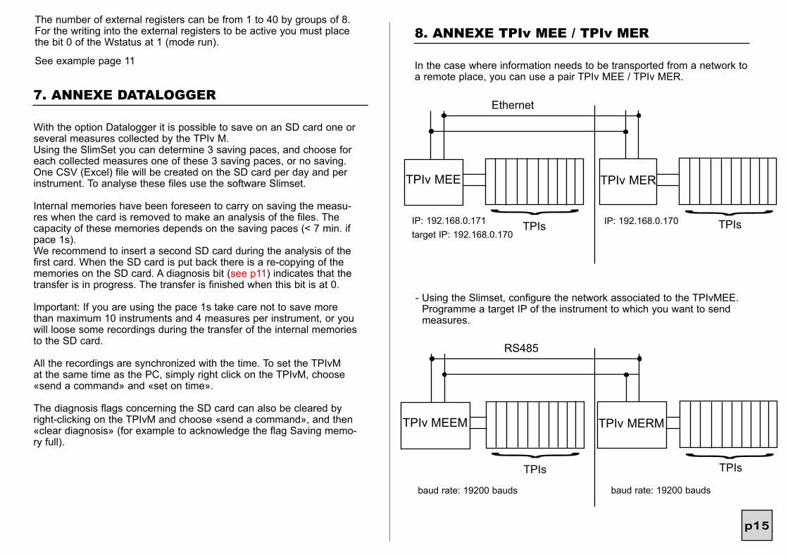
8. ANNEXE TPIv MEE / TPIv MER
In the case where information needs to be transported from a network to a remote place, you can use a pair TPIv MEE / TPIv MER.
- Using the Slimset, configure the network associated to the TPIvMEE. Programme a target IP of the instrument to which you want to send measures.
TPIv MEE TPIv MER
Ethernet
IP: 192.168.0.171target IP: 192.168.0.170
IP: 192.168.0.170
TPIs TPIs
TPIv MEEM TPIv MERM
RS485
baud rate: 19200 bauds
TPIs TPIs
baud rate: 19200 bauds
The number of external registers can be from 1 to 40 by groups of 8.For the writing into the external registers to be active you must place the bit 0 of the Wstatus at 1 (mode run).
See example page 11

p16
TPIv MER: 4 relay outputs (TPIs 4R) parameter relay output 1: external register 1 (corresponds to the taken up measure #1) parameter relay output 2: external register 2 (corresponds to the taken up measure #2) parameter relay output 3: external register 3 (corresponds to the taken up measure #3) parameter relay output 4: external register 4 (corresponds to the taken up measure #4)
In the case of a communication problem between the TPIv MEE and the TPIv MER error flags will be positionned on each TPIvM (they can be seen in reading of the measures using the Slimset).
- Using the Slimset, configure the network associated to the TPIv MER, knowing that to each taken up measure of the network associated to the TPIv MEE will correspond an external register of the TPIv MER.
Eg. I you want to send 4 logic inputs on 4 relays
TPIv MEE with 4 measures taken up:
#1 TOR1 1354-0045 #2 TOR2 1354-0045 #3 TOR3 1354-0045 #4 TOR4 1354-0045
9. ANNEXE CALCULATIONS (OPTION C)
Example of formula:if ((Measure 1 ≥ constant 0) AND (Measure 4 = True)) then (True)
Constant 0 = 525°Measure 1 = Measure of the temperature of a furnaceMeasure 4 = logic input
If the temperature of the furnace is ≥ 525° and if the logic input is active then the result of the formula is true.
10. ANNEXE PROFIBUS
1) First install the provided GSD file:ARSF0F62.gsf (French)ARSF0F62.gsd (English)
2) Configuration of the modulesInput modules: choice among 50 collected measures and 50 diagnosises asso-ciated with these measures.Modules of outputs: choice among 15 registers of the TPIv M (can be used only with the option Y).
3) Choice of the parametersThe format of the measures must be programmed in the user parameters.
4) The station number must be programmed with the SlimSet once the TPIv M network architecture is programmed.
Note: the station number can be configured by the PLC using a command class 2 set/change Slave Address.
With the option C you can have on the TPIv M 20 calculation formulas, pro-grammable in a dynamic way, using operators, pre-defined functions, collected measures, external registers of the TPIv M and 60 programmable constants. You can create groups of measures in order to perform operations directly on the whole group.These 20 results can be directly associated with all the instruments of the network.
Diagnosis message (3 bytes):
3
general diagnosissee page 8 for the detail of the errors


