TECHNICAL REPORT ARLCB-TR-83045
MECHANICAL PROPERTIES OF
SILICONE RUBBER IN A CLOSED VOLUME
G. P. O'HARA
DECEMBER 1983
US ARMY ARMAMENT RESEARCH AND.DEVELOPMENT CENTERLARGE CALIBER WEAPON SYSTEMS LABORATORY
BENEI' WEAPONS LABORATORYWATERVLIET N.Y. 12189
__ APPROVED FOR PUBLIC RELEASE; DISTRIBUTION UNLIMITED
ELEcTE f
S ~ ~ FED 13 0O'.

DISCIAINER
The findings in this; report are not to be construed as an official
Departwnt of the Army position unless so designated by other
aut:horized docmens.
The use off trade amne(s) and/or wwnfactwrer(s) in this report does
not constitute an official indarrsemnt or apprval.
DheestrYoyi atrthis report when it is no longe needed. Do not return it to !
the oriinator

SECURITY CLASSIFICATION OF THIS PAGE (M01n Date _ _ _ _ _ _ _
REPORT DOCUMENTATION PAGE BEFORE COMPLETIIG FORMI; REPORT NUMBER 2. GOVT ACCESSION NO. 3. RECIPIENT'S CATALOG NUMmER
IARLCB-TR-83045 _ _ __a
I 4. TITLE (and Subtilel) -- S. TYPE OF REPORT •PERIOD COVERED
MECHANICAL PROPERTIES OF SILICONE RUBBER IN A
CLOSED OLUME Final6. PERFO'RMING ORG. RMPORT NUMBER
7. AUTHOR(*) S. CJNTRACT OR GRANT NUMBER(&)
G. P. O'Hara
9. PERFORMING ORGANIZA1 ION NAME AND ADDRESS 10. PROGRAM ELEMCNT, PROJECT, TASK
S. PEF~fl4INGAREA & WORK UNIT NUMBERS
US Army Armament Research & Development Center .MCMS No. 2080.15.6000.0Benet Weapons Laboratory, DRSMC-LCB-TL PRON No. 1A1221B81AIAWatervliet, NY 12189 __
11. CONTROLLING OFFICE NAME AND ADDRESS I. REPORT DATE
US Army Armament Research & Development Center December 1983Large Caliber Weapon Systems Laboratory 13. NUMBER OF PAGES
Dover, NJ 07801 1414. MONITORING AGENCY NAME & ADDRESS(I dilferent tea ConbalhW Osffge) IS. SECURITY CLASS. (of thle report)
UNCLASSI FIED
ISa. DECL AS31FI CATION/DOWN GRADINGSCHEDULE
IS. 7)STRIBUTION STATEMENT (ft thi Report)
Approved for public release; distribution unlimited.
17. DISTRISUrMON STATEMENT (of the abstrat tnteed in Block 20, I tltfetat fi Report)
1S. SUPPLEMENTARY NOTES
li. KEY WORDS (Continue an rever aide Itf nec** amrd0t Pdndf bgoy ocktmber)
Aubber ExperimentModulus ElastounrSilicone Pressure
.1 AsSYVIACY Vmu don~ t-es ebb N naoo a" deftr by blook nun~orI
This report covers an experiment to measure the mechanical properties oi foursamples of RTV silicone rubber. The test was conducted under conditions ofsmall strains and an elevated hydrostatic pressure component of stresa (0 -4000 psi). The results gave a Young's modulus in the range of 13,000 to 21,000and a Poisson's ratic r4nge of 0.48 to 0.49. The Yotng's modulus valuee were
much higher than tht usual tensile values; however, a calculation of bulkmoduluo gave values which were within the accepted range.
D J IM 473 Eo orlw•vs oes.LTe UNCLASSIFIED
SZCUIT'y CLASSIFICATION OF THIS PAE (1eM Date Eatier)
7 ,,,,-

TABLE OF CONTENTS
Paige
INTRODUCTION 1
TEST PROCEDURE
DATA REDUCTION 2
CALIBRATION 2
SAMPLE PREPARATION 3
RESULTS 4
DISCUSSION 6
CONCLUSION 8
TABLES
I. SILICONE RUBBER MECHANICAL PROPERTIES (CLOSED VOLUME) 4
LIST OF ILLUSTRATIONS
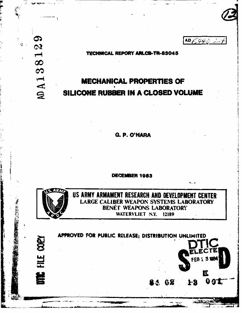
1. Silicone Rubber Test - Closed Volume Test Fixture. 9
1. Silicone Rubber Test Mechanical Properties - Young's 10Modulus vs. Pressure.
3. Silicone Rubber Test Mechanical Properties - 'issons 11Ratio vs. Pressure.
4. Silicone Rubber Test Mechanical Properties - Bulk 12Modulus vs. Pressure.
5. Silicone Rubber Test Mechanical Properties - Shear 13Modulus vs. Pressure.
Aocession ForNTIS GRA&I
DTIC TABUnannouncedJustification
Distribution/Availability Codes
Avail and/orlIt Special

-FýINTRODUCTION
This report covers an experiment to evaluate the mechanics of RTV
silicone rubber products under conditions of mall strain coupled with a high
hydrostatic component of stress. This condition gives a deviatoric stress
component which is small relativt to the total stress which may produce
certain computational difficulties. A conventional uniaxial compression or
tension experiment will yield a value of Poisson's ratio of nearly 0.5 and a
Young's modulus of about 1000 psi. In this work a cylindrical compression
test specimen was restrained by a steel tube to limit radial deformation. The
tube was then instrumented to measure the radial stresses and strains. The
average axial stress and strain ware derived from the testing machine load and
crosshead movement. When this data was reduced, the Poisson's ratio was in
the range of 0.48 to 0.49 and Young's modulus was in the range of 13,000 to
21,000. These very high modulus values were not expected and they do not seem
to correlate with shore 'A' hardness values.
TEST PROCEDURE
The test fixture is shown in Figurq 1. It is a steel cylinder of wall
ratio 1.1 with steel end closures. The load was applied in a 120,000 pound
universal testing machine set up as a compression test device. The data
recorded was:
1. Total load.
2. Crosshead movement.
3. Circumferential strain on the exterior of the cylindar.
4. Axial strain on the exterior of the cylinder.
i.1

The first three date iteas were used to calculate the Young's modulus and
Poisson's ratio of the ILTV u,,irg a strength of materials approach. The last
item was used to checai assumed condition of zero friction between the steel
cylinder and the RTV sample.
DATA REDUCTION
A computer program was written in Fortran 77 to reduce the experimental
data. This program performed all required data reduction and checking
calculations. A list of these functions is:
1. The zaro point correction.
2. Calculate axial strain in the RTV.
3. Calculate radial strain in the RTV.
4. Cal-, Alate axial stress in the RTV.
5. Calculate radial stress in the RTV.
6. Calculate Young's wodulue of the RTV.
7. Calculate Polsson's ratio of the RTV.
8. Calculate bulk modulus of the RTV.
9. Calculate shear modulus of the RTV.
1,). Check the tist conditions.
11. Print out the results.
CALIBRATION
Two calibrations were performed. First, a simple experiment was
performed to determine Young's modulus for the steel cylinders so that
cylinder calculations could be performed using standard Lame' thick-walled
equa.1,- for an open-end cylinder. After the four silicone samples were
2
__ _ __ _ _ __

tested,, a hydraulic pressure was applied to each of the two test crlinders;
and the recorded strains vere entered into the data reduction program as a
final check on the assumed properties of the cylinder.
A second check on the test was performed by running a finite element
ntress analysis on the test fixture using a typical set o~f data from the
experiment. Sample experimental data was extracted from the finite element
results and e~tered into the data reduction program. This was done for
assummed silicone-steel friction coefficients of 3.0, 0.1, and 0.2. It was
shown that zhe assumption of zero friction was justified and a coefficient of
0.1 would produce a very large error In the results.
SAMIPLE PREPARATION
The test was performed on four samples of RTV silicone rubber supplied by
the General Electric Silicone Products Division in Waterford, NY. The
material was hand mixed in 600 to 800 gram batches, vacuumed, degassed, and
cast directly into one of the two test cylinders. A ratio of ten to one by
weight of parts 'A' and 'BI was carefully used. The four samples are defined
in Table I.
43

TABLE I. SILICON& RUBUBB MCHiANICAL PIOPERTIES (CLOSED OLUlE)
Staple Definition of the Moterial.
Shore Specific Mass# Type Color 'A' Cure Gravity Sa.
I RTV-660 White 38 R.T. 1.15 1538
2 RTV-66-1 Blue- 52 R.T. 1.25 1698Grey
3 RTV-664 Blue 58 160*F 1.25 16686 hrs.
4 PRTV-680 Beige 69 160hF 1.49 19366 hrs.
RESULTS
Figuras 2 and 3 show the basic results that wmer desired. For a further
check, the bulk modulus and shear modulus were calculated from the two basic
properties. These results are shown in Figures 4 and 5. There were several
other more subjective observations which should be noted.
One early observation was that Ly cast:Lng the samples in the test
cylinders, an excellent fit was obtained due to the small shrinkage during
curing. This was best displayed by the RTV-660 sample which had to be cooled
in a storage freezer before it could be removed. The rest could be carefully
slid in or out of the cylinder. This d4monstrated a small gap between the
silicone and the steel cylinder which would have to be closed before any
radial contact could be achieved. This effect, added to a poor experlmental
sensitivity, pruduced a large scatter in the data at Low pressures.
4
V _ _ _ _ _ _ _ _ _ _ _ _ _ _ _

Another observation was the degreQ of extrusion or cutting of the samp!e
at the joint between the &teel tube and the end caps. This effect limited the
test load on the RTV-660 ample to a low value and established the maximum
load for the other samples. The RTV-680 sample showed no damage due to this
problem. However, in no case was any large damage allowed.
After the test was completed, two of the samples were split in half
length.ise to inspect for casting defects. We saw only some minor color
variations which ware also visible on the exterior of the specimens. This
verified the qmality of the casting procedure which is regularly used at G.E.
Silicone Products.
One detail seems to have produced sorn interesting results, although it
did not seem to be important at the time. The first 664 sample was cast from
several one pound kits which were about two years old. The second (number 3)
sample was prepared from a fresh 55 pound can. The difference was in the S''
part of the mix which was the smaller quantity. In the older material the
pigment had settled out and was very difficult to romix (in the small 0.09
pound bottle), so a small quantity of fresh material was used to make up the
ten to one mix ratio, In this case some of the weight of pigment was replaced
by reagent chemicals. This produced more cross-linking of the basic polymer
than would occur in an accurately mixed material* The extra cross-linking of
the polymer produced an increase in Young's modulus and a decrease in
Poisson's ratio. Also noted :n the first sample was a change in the pigment
content as evidenced by the slight difference in color when the *.ite 'A' part
was mixed with the dark blue 'b' part. To help clarify this point, the
pigment serves two purposes. First, it aids the evaluation of the mixing
5

process, and second, it helps preserve a ten to one nixing ratio for many
compounds.
DISCUSSION
The first point that should be noted is that there ti little correlation
between shore 'A' hardness and either Young's modulus or shear modulus which
are closely related. However, there is a correlation between shore hardness
and bulk modulus. This should be expected because this type of hardness test
is essentially a compression test in a closed volume. Add to this the
nonlinear relation between bulk modulus (B), Young's modulus (K), and
Poisson's ratio (M).
3(1.0 - 2.0 M.)
In this case a small change in Polsson's ratio can make a large change in bulk
uodulus as Poisson's ratio approaches 0.5. This is the dominant effect. The
RTV-664 sample made from older material had more crcss-linking which produced
a larger Young's modulus and a smaller Poisson's ratio, which combined toproduce a smaller bulk modulus and consequently a small hardness value. This
brings up an old question. What do 'hardness' tests actually measure?Summary of important points-
1. The Young's modulus had a very high value.
2. The two RTV-664 smples yielded rather different results.
3. The btlk modulus results seem to be reasonable.
4. The RTV-660 test was cut off at a lower load because of extrusion
around the end caps.
6
di*Iml/I

tU
5. Two samples were cut in half to check for interior voids and no
visible ones more found.
6. The samples were all removed from the test in one piece. However,
the RTV-660 ample had to be chilled to about O'.
7. The data under 1000 psi pressure was not reliable because of poor
sensitivity of the strain masurement.
8. The difference between the two RTV-664 samples was rulated to the age
of the material which came from two different lots about two years
apart in manufacture.
9. The shore 'A' hardness correlates with bulk. modulus.
10. Young's modulus and Poisson's ratio are independent properties.
11. There may be a difference In the cross-linking of the two RTV-664
samples.
12. The difference in color between the two RTV-664 samples was created
by settling out of the dark blue pigment in the 'B' component of the
older material. In this case some never part 'B' was added to make
up the correct weight.
13. The RTV-680 was not in production at the time of the test, so a small
custom lot was nade for our purposes.
14. It is logical that increased cross-linklng would produce a higher
Young's modulus end lower Poisson's ratio, but why would this result
in a lower bulk modulus and shore hardness?
7

I!
CONCLUSIONI
The mechanical properties of rubber like materials derived from
conventional tensile or compression tests can yield misleading results *hen a
high pressure component of stress Is present. This problem must be solved
using special material propertieo or other constittivtve relations.
Iif
SILICONE RUBBER TESTCLCSED VOUME
TEST FIXTUE
LOAD
SILICONE
*.:.. . . :..:.. . STEEL
3.251? DIA.
Fig. II 9

C4
LLI-
0+0
0h 0 c40 0 400CL.
z)
a10

~co
16
00 02
cooLU 0
0 0 4S4n
d aa

C141
LIA.
LLI-
INC 0
40o zz )0S
('I I
w1

00
cm
0-+
CD 0 0i
Ii00Mso
*113

READER EVALUATION
Please take a few minutee to complete the quesrlorcnaire bcýiw and roturn tc usat the following address: Commander, Armament Research and De',elopasntCenter, U.S. Army AMCCOH, ATTN: Technical Publications, DRSMC-LCB-TL,Watervliet, NY 12189.
i. Benet Weapons Lab. Report Number
2. Please evaluate this publication (check off one or more as applicable).Yes No
Information RelevantInformation Technically SatisfactoryFormat Easy to UseOverall, Useful to My WorkOther Comeents
3. Has the report helped you In your own areas of interest? (i.e. preventingduplication of effort in the same or related fields, savings of time, ormoney).
4. How is the report being used? (Source of ideas for new or ImprovedIr designs. Latest information, on current, statft of the art, etc.).
5. How do you think this type of report c-uld be changed or revised toimprove readability, usability?
6. Would you like to communicate directly with the author of the reportregarding subject matter or topics not covered in the report? If soplease fill in the following information.
Name:
Telephone Ntaber:
Organitatioi• Address:
L.,,...,- .... ..... . -. _ -- • ' -

TECHNICAL REPORT INTERNAL DISTRIBUTION LIST,
NO. OFCOPIES
CHIEF, DEVELOPMENT ENGINEERING BRANCHAlTN: DRSMC-LCB-D 1
-DP I-DR 1-DS (SYSTEMS) 1-DS (ICAS GROUP) 1-DC 1
CHIEF, ENGINEERING SUPPORT BRANCHATTN: DRSMC-LCB-S 1
-SE I
CHIEF, RESEARCH BRANCHATTN: DRSMC-LCB-R 2
-R (ELLEN FOGARTY) I-RA I-RM I-RP I-RT I
TECHNICAL LIBRARY 5ATTN: DRSMC-LCB-TL
TECHNICAL PUBLICATIONS & EDITING UNIT 2ATTN: DRSMC-LCB-TL
DIRECTOR, OPERATIONS DIRECTORATE I
DIRECTOR, PROCUREMENT DIRECTORATE I
DIRECTOR, PRODUCT ASSURANCE DIRECTORATE 1
4
NOTE: PLEASE NOTIFY DIRECTOR, BERiT WEAPONS LIAORATORY, ATTN: DRSMC-LCB-TL,OF ANY ADDRESS CHANGES.
K

rECINICAL REPORT EXTERNAL DISTRIAUTION LIST (CONT'D)
No. id tic. orCOPIES COPIES
COM4MANDER DIRECTORUS ARMY MATERIALS & MECHANICS US NAVAL RESEARCH LAB
RESEARC E CTER 2 TTN: DIR, NECK DIVATTN: TECI LIB - DRXNR-PL CODE 26-27, (DOC LIB)WATERTOWN, MA 01272 WASHINGTON, D.C. 20375
COMNMANDER COMMANDERUS ARMY RESEARCH OFFICE AIR FORCE ARtamENT LABORATORYATTN: CHIEF, IPO I TTN: AFATL/DLJ1P.O. BOX 12211 &Ie&TL/DLJG
RESEAR.CH TRIANGLE PARK, C 27709 ELIN AFB, FL 32542
COMMANDER METALS & CERAMICS INFO CTRUS ARMY HARRY DIAMDND LAB BATTELLE COLUMBUS LABATTN: TECH LIB 1 505 KING AVENUE
2800 POWDER MILL ROAD COLUMBUS, OH 43201AOELPHIJ%, MD 20783
COM4MANDER
NAVAL SURFACE WEAPONS CTRATTN: TECHNICAL LIBRARY 1
CODE X212DAHLGREN, VA 22448
NOTE: PLEASE NOTIFY COMMANDER, ARMAMNT RESEARCH AND DEVELOPMENT CENTER,US ARMY ANCCOK, ATTN: BWNKT WWAPONS LAJROIUTCRY, DP.SHC-LCB-TL,WATERVLIET, NY 12189, OF ANY ADDRESS CHANGES.
- -- ' ' - ", "" " ,it .. • . .r * ,

TECHNICAL EPORT EXTERNAL DISTRIBUTION LIST
VO. OF NO. OFCOPIES COPIES
ASST SEC OF THE AyMY COMMANDERPISEARCH & DEVELOPMENT US ARMY ANCCOMATTN: DEP FOR SCI & TECH I ATTN: DRSMC-LEP-L(R)THE PENTAGON ROCK ISLAND, IL 61299WASHINGTON, D.C. 20315
COMMANDERCOMMANDER ROCK ISLAND ARSENALDEFENSE TECHNICAL INFO CENTER ATTN: SMICRI-ENM (MAT SCI DIV)ATTN: DTIC-DDA 12 ROCK ISLAND, IL 61299CAMERON STATIONALEXANDRIA, VA 22314 DIRECTOR
US ARMY INDUSTRIAL BASE ENG ACTVCOMMANDER ATTN: DRXIB-MUS ARMY MAT DIV & READ COW ROCK ISLAND, IL 61299ATTN: DRCDK-SG5001 EISENHOWER AVE COIGIANDSRALEXANDRIA, VA 22333 US ARMY TANK-AUTMV R&D COND
ATrN: TECH LIB - DRSTA-TSLCOM•ANDER WAREN, MI 48090ARMAMENT RES & DEV CTRUS ARMY A4CCOI4 CDMMANr3RATTN: DRSMC-LC(D) I US ARMY TANK-AUTMV COND
DRSMC-LCE(D) 1 ATTN: DRSTA-RCDRZM4C-LCN(D) (BLDG 321) 1 WRZN, MI 48090DRSMC-LCS(D) IDRSMC-LCU(D) 1 COMMANDERDRSMC-LCW(D) 1 US MILITARY ACADEMYDRSHC-SC1-O (PLASTICS TECH I ATTN. CHMN, MECH ENGR DEPT
EVAL CTR, WEST POINT, NY 10996BLDG. 351N)
DRSMC-tSS(D) (STINFO) 2 US ARMY MISSILE COMDDOVER, NJ 07801 REDSTONE SCIENTIFIC INFO CTR 2
ATTN: DOCUMENTS SECT, BLDG. 4484
DIRECTOR REDSTONE ARSENAL, AL 35898BALLISTICS RESEARCH LABORATORYARMAMENT LRSEARCH & DEV CTR IOMMANDERUS ARMY ANOCON 1 US ARMY FGN SCIENCE & TECH CYRATTN: D&SMC-TSB-S (STINFO) ATTN: DRXST-SDADERDEEN PROVING GROUND, HD 21005 220 7TH STREET, N.E.
CHARLOTTESVILLE, VA 22901
MATERIEL SYSTMIS ANALYSIS ACTVATTN: DRSXY-NPABERDEEN PROVING GROUND, ND 21005
NOTE: PLEZAS NOTIFY COMMANDER, ARMAMENT RESEARCH AND DEVELOPMENT CENTER,"-'--US MW AMLq=M, ATTN: BZNIT WAPONS LABUR)ITOit, [DtSMC-ICW-TL,
- WATERVLIET, NY 12189, OF ANY ADDRESS CLANGES.
f1._


