Mini Lecture
NYU WIRELESS
Industrial Affiliates
Spectrum Frontiers: Terahertz Prof. Ted Rappaport
NYU WIRELESS
February 17, 2021
2
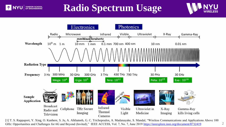
Radio Spectrum Usage
[1] T. S. Rappaport, Y. Xing, O. Kanhere, S. Ju, A. Alkhateeb, G. C. Trichopoulos, A. Madanayake, S. Mandal, “Wireless Communications and Applications Above 100
GHz: Opportunities and Challenges for 6G and Beyond (Invited),” IEEE ACCESS, Vol. 7, No. 7, June 2019 https://ieeexplore.ieee.org/document/8732419

3
Unlicensed Operation
• Maximum EIRP of 40 dBm (average) and 43 dBm (peak)
for mobile.
• Maximum EIRP of 82-2 ×(51- 𝐺𝑇𝑋) dBm (average) and
85-2 ×(51- 𝐺𝑇𝑋) dBm (peak) for fixed point-to-point.
• Out-of-band emission limit 90 pW/cm2 at three meters.
FCC ET DOCKET 18-21 SPECTRUM HORIZONS
New Consumer Usage above 100 GHz
http://mmwavecoalition.org/wp-content/uploads/2019/02/DOC-356297A1-FCC-Report-Order.pdf
https://www.fcc.gov/document/fcc-opens-spectrum-horizons-new-services-technologies-0
Frequency Band
(GHz)
Contiguous Bandwidth
(GHz)
116-123 7
174.8-182 7.2
185-190 5
244-246 2
Total 21.2
• Frequency within 95 GHz to 3 THz.
• No interference protection from pre-allocated services.
• Interference analysis before license grant.
Spectrum Horizons Experimental Radio Licenses
FCC Approved on March 15th 2019
• Rules on Licensed spectrum deferred until sufficient
technical and market data is obtained (NYU Thrust area).Only 16 % of the available spectrum (116-246 GHz),
primarily due to the forbidden bands in US246

Applications Above 100 GHz
4
mmWave & THz Applications—the potential for 6G [1]
Wireless CognitionRobotic Control [27, 28]
Drone Fleet Control [27]
Sensing
Air quality detection [5]
Personal health monitoring system [6]
Gesture detection and touchless smartphones [7]
Explosive detection and gas sensing [8]
Imaging
See in the dark (mmWave Camera) [9]
High-definition video resolution radar [10]
Terahertz security body scan [11]
Communication
Wireless fiber for backhaul [12]
Intra-device radio communication [13]
Connectivity in data centers [14]
Information shower (100 Gbps) [15]
Positioning Centimeter-level Positioning [9,16]
[1] T. S. Rappaport, Y. Xing, O. Kanhere, S. Ju, A. Alkhateeb, G. C. Trichopoulos, A. Madanayake, S. Mandal, “Wireless Communications and Applications
Above 100 GHz: Opportunities and Challenges for 6G and Beyond (Invited),” IEEE ACCESS, submitted Feb. 2019.
IBM Research
5
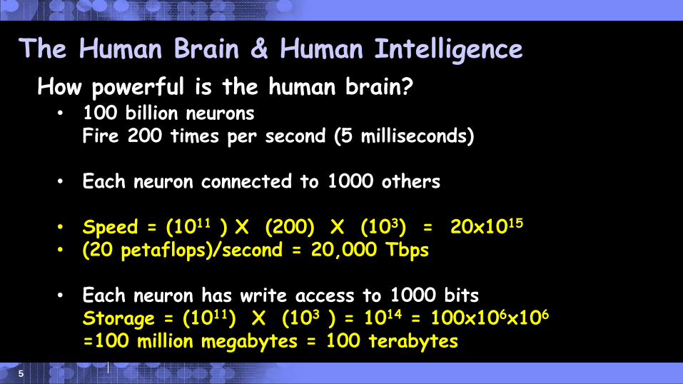
The Human Brain & Human Intelligence
How powerful is the human brain?• 100 billion neurons
Fire 200 times per second (5 milliseconds)
• Each neuron connected to 1000 others
• Speed = (1011 ) X (200) X (103) = 20x1015
• (20 petaflops)/second = 20,000 Tbps
• Each neuron has write access to 1000 bitsStorage = (1011) X (103 ) = 1014 = 100x106x106
=100 million megabytes = 100 terabytes
IBM Research
NYU WIRELESS
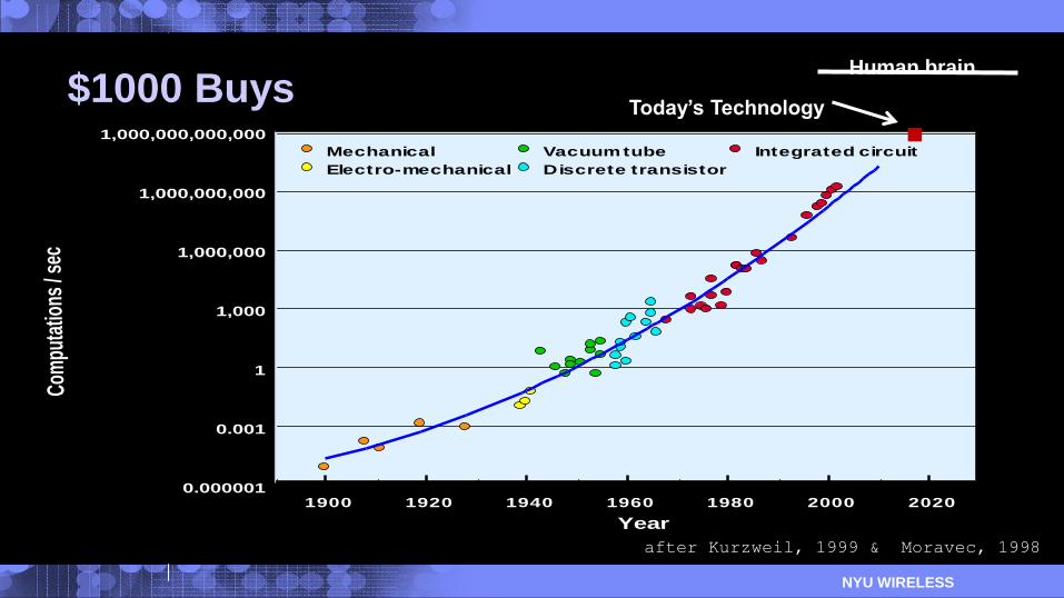
$1000 Buys
1900 1920 1940 1960 1980 2000 2020
1E-6
1E-3
1E+0
1E+3
1E+6
1E+9
1E+12
Mechanical
Electro-mechanical
Vacuum tube
Discrete transistor
Integrated circuit
Year
1,000,000,000,000
1,000,000,000
1,000,000
1,000
1
0.001
0.000001
Com
puta
tions
/ se
c
after Kurzweil, 1999 & Moravec, 1998
Human brain
Today’s Technology

IBM Research
NYU WIRELESS
$1000 Buys
1900 1920 1940 1960 1980 2000 2020
1E-6
1E-3
1E+0
1E+3
1E+6
1E+9
1E+12
Mechanical
Electro-mechanical
Vacuum tube
Discrete transistor
Integrated circuit
Year
1,000,000,000,000
1,000,000,000
1,000,000
1,000
1
0.001
0.000001
Com
puta
tions
/ se
c
after Kurzweil, 1999 & Moravec, 1998
Human brain
Today’s Technology
2036
IBM Research
8
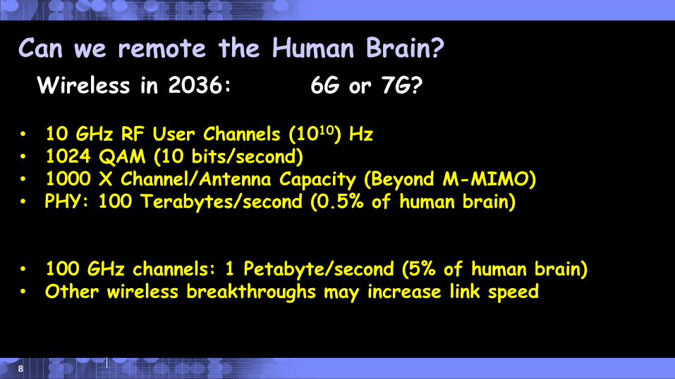
Can we remote the Human Brain?
Wireless in 2036: 6G or 7G?
• 10 GHz RF User Channels (1010) Hz • 1024 QAM (10 bits/second)• 1000 X Channel/Antenna Capacity (Beyond M-MIMO)• PHY: 100 Terabytes/second (0.5% of human brain)
• 100 GHz channels: 1 Petabyte/second (5% of human brain)• Other wireless breakthroughs may increase link speed
Applications Above 100 GHz
9
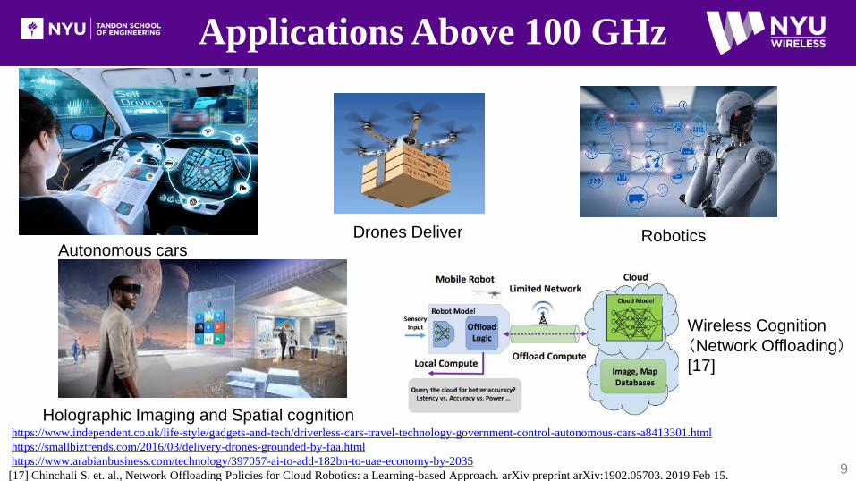
Holographic Imaging and Spatial cognition
Autonomous cars Drones Deliver Robotics
https://www.independent.co.uk/life-style/gadgets-and-tech/driverless-cars-travel-technology-government-control-autonomous-cars-a8413301.html
https://smallbiztrends.com/2016/03/delivery-drones-grounded-by-faa.html
https://www.arabianbusiness.com/technology/397057-ai-to-add-182bn-to-uae-economy-by-2035
[17] Chinchali S. et. al., Network Offloading Policies for Cloud Robotics: a Learning-based Approach. arXiv preprint arXiv:1902.05703. 2019 Feb 15.
Wireless Cognition
(Network Offloading)[17]
Applications Above 100 GHz
10
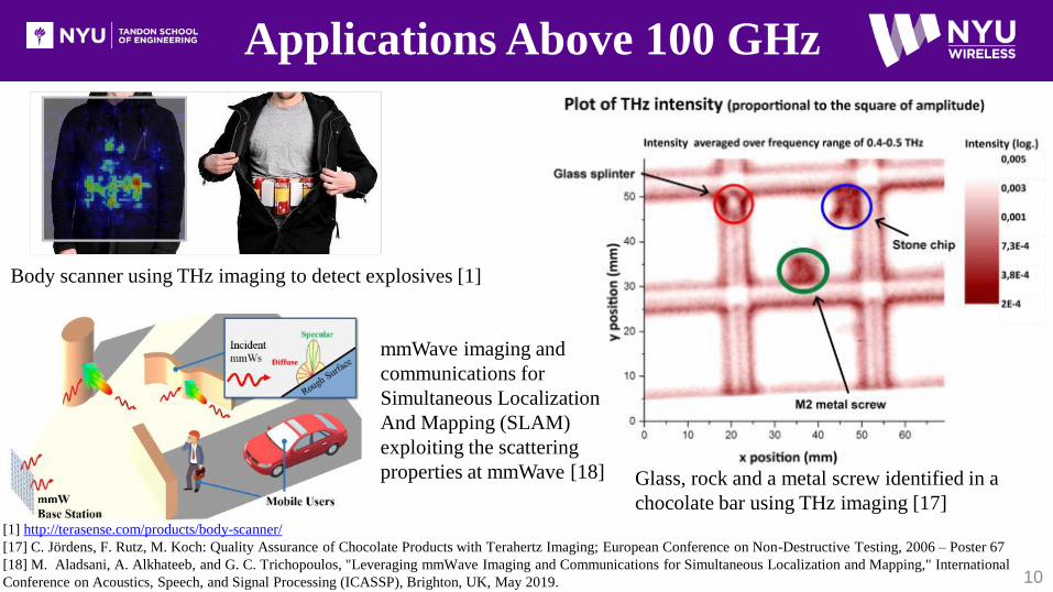
Glass, rock and a metal screw identified in a
chocolate bar using THz imaging [17]
[1] http://terasense.com/products/body-scanner/
[17] C. Jördens, F. Rutz, M. Koch: Quality Assurance of Chocolate Products with Terahertz Imaging; European Conference on Non-Destructive Testing, 2006 – Poster 67
[18] M. Aladsani, A. Alkhateeb, and G. C. Trichopoulos, "Leveraging mmWave Imaging and Communications for Simultaneous Localization and Mapping," International
Conference on Acoustics, Speech, and Signal Processing (ICASSP), Brighton, UK, May 2019.
Body scanner using THz imaging to detect explosives [1]
mmWave imaging and
communications for
Simultaneous Localization
And Mapping (SLAM)
exploiting the scattering
properties at mmWave [18]
Applications Above 100 GHz
11
[2] http://terapod-project.eu/wp-content/uploads/2018/03/Re-imagining-data-centres-with-THz.pdf
[3] https://www.rfglobalnet.com/doc/fujitsu-develops-low-power-consumption-technology-for-g-0001
[12] T. S. Rappaport, et al., “Overview of millimeter wave communications for fifth-generation (5G) wireless networks-with a focus on propagation models,” IEEE Trans. on Ant. and Prop.,
vol. 65, no. 12, pp. 6213–6230, Dec. 2017.
[20] S. Abadal, A. Marruedo, et al., "Opportunistic Beamforming in Wireless Network-on-Chip", in Proceedings of the ISCAS ’19, Sapporo, Japan, May 2019.
[30] S. Sun et al. "MIMO for millimeter-wave wireless communications: beamforming, spatial multiplexing, or both?," in IEEE Comm. Magazine, vol. 52, no. 12, pp. 110-121, De. 2014.
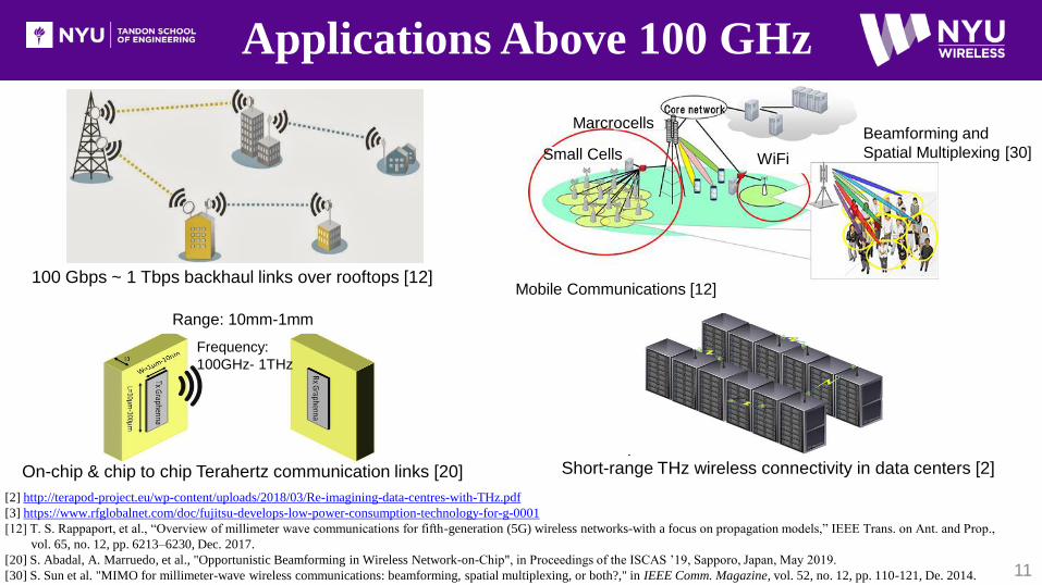
100 Gbps ~ 1 Tbps backhaul links over rooftops [12]
Short-range THz wireless connectivity in data centers [2]On-chip & chip to chip Terahertz communication links [20]
Mobile Communications [12]
Small Cells
Marcrocells
WiFi
Beamforming and
Spatial Multiplexing [30]
Range: 10mm-1mm
Frequency:
100GHz- 1THz

Atmospheric absorption beyond the natural Friis free space path loss [1]
Sea level
standard
Z=10 km
Sea level dry
Z=10 km
Standard Atmosphere
Standard Atmosphere
Dry Atmosphere
Dry Atmosphere
Propagation Fundamentals above 100 GHz
on earth (1/2)
12[1] Y. Xing and T. S. Rappaport, “Spectrum Coexistence between Active and Passive Systems in Space and on the Ground at Frequencies above 100 GHz (Invited),”
in submission to IEEE Communication Letters, Feb. 2021, pp. 1-5.
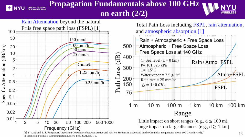
@ Sea level (z = 0 km)
P= 101.325 kPa
T= 15∘CWater vapor = 7.5 g/𝑚3
Rain rate = 25 mm/hr
𝑓𝑐 = 140 𝐺𝐻𝑧
Rain+Atmo+FSPL
Atmo+FSPL
FSPL
Propagation Fundamentals above 100 GHz
on earth (2/2)
13
Rain Attenuation beyond the natural
Friis free space path loss (FSPL) [1]Total Path Loss including FSPL, rain attenuation,
and atmospheric absorption [1]
Little impact on short ranges (e.g., d ≤ 100 m),
huge impact on large distances (e.g., d ≥ 1 km)[1] Y. Xing and T. S. Rappaport, “Spectrum Coexistence between Active and Passive Systems in Space and on the Ground at Frequencies above 100 GHz (Invited),”
in submission to IEEE Communication Letters, Feb. 2021, pp. 1-5.
Pat
hL
oss
(dB
)Range

Description Specification
LO Frequency 22.5 GHz ×6 = 135 GHz
IF Frequency 5-9 GHz (4 GHz bandwidth)
RF Frequency 140-144 GHz
Upconverter IF input -5 dBm typically
10 dBm (damage limit)
Downconverter RF input -15 dBm typically
0 dBm (damage limit)
TX output power 0 dBm
Antenna Gain 25 dBi / 27 dBi
Antenna HPBW 10º / 8º
Antenna Polarization Vertical / Horizontal
Free Space Path Loss: 28, 73, 140 GHz
NYU 140 GHz Channel Sounder System
[23] Y. Xing, O. Kanhere, S. Ju, T. S. Rappaport, G. R. MacCartney Jr., “Verification and calibration of antenna cross-polarization discrimination and penetration loss for
millimeter wave communications,” 2018 IEEE 88th Vehicular Technology Conference, Aug. 2018, pp. 1–6. 14
As expected, FSPL at 140/73/28 GHz follows the Laws of Physics
and satisfies Friis’ equations with antenna gains removed.
FSPL verifications following the proposed method
at 28, 73, and 140 GHz [23] (after removing antenna gains)
𝐅𝐫𝐢𝐢𝐬′ 𝐅𝐒𝐏𝐋:𝑷𝒓𝑷𝒕= 𝑮𝒕𝑮𝒓
𝝀
𝟒𝝅𝒅
𝟐
𝐀𝐧𝐭𝐞𝐧𝐧𝐚 𝐠𝐚𝐢𝐧:𝑮 =𝑨𝒆𝟒𝝅
𝝀𝟐
𝑨𝒆 = 𝟐. 𝟗 𝒄𝒎𝟐 ,𝐜𝐨𝐧𝐬𝐭𝐚𝐧𝐭 𝐨𝐯𝐞𝐫 𝒇
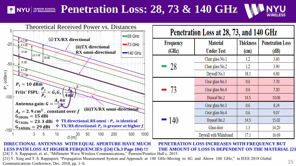
Penetration Loss: 28, 73 & 140 GHz
(i)TX/RX directional
(ii)TX directional
RX omni-directional
(iii)TX/RX omni-directional
DIRECTIONAL ANTENNAS WITH EQUAL APERTURE HAVE MUCH
LESS PATH LOSS AT HIGHER FERQUENCIES ([24] Ch.3 Page 104) !!!
𝑷𝒕 = 𝟏𝟎 𝐝𝐁𝐦
𝐆𝟐𝟖𝐆𝐇𝐳 = 𝟏𝟓 𝐝𝐁𝐢𝐆𝟕𝟑𝐆𝐇𝐳 = 𝟐𝟑. 𝟑 𝐝𝐁𝐢𝐆𝟏𝟒𝟎𝐆𝐇𝐳 = 𝟐𝟗 𝐝𝐁𝐢
𝐓𝐗 𝐝𝐢𝐫𝐞𝐜𝐭𝐢𝐨𝐧𝐚𝐥, 𝐑𝐗 𝐨𝐦𝐧𝐢 ∶ 𝑷𝒓 𝐢𝐬 𝐢𝐝𝐞𝐧𝐭𝐢𝐜𝐚𝐥 𝐓𝐗 𝐑𝐗𝐝𝐢𝐫𝐞𝐜𝐭𝐢𝐨𝐧𝐚𝐥: 𝑷𝒓 𝐢𝐬 𝐠𝐫𝐞𝐚𝐭𝐞𝐫 𝐚𝐭 𝐡𝐢𝐠𝐡𝐞𝐫 𝒇
Theoretical Received Power vs. Distances
15
PENETRATION LOSS INCREASES WITH FREQUENCY BUT
THE AMOUNT OF LOSS IS DEPENDENT ON THE MATERIAL [21] [24] T. S. Rappaport, et. al., “Millimeter Wave Wireless Communications,” Pearson/Prentice Hall c. 2015.
[21] Y. Xing and T. S. Rappaport, “Propagation Measurement System and Approach at 140 GHz-Moving to 6G and Above 100 GHz,” in IEEE 2018 Global
Communications Conference, Dec. 2018, pp. 1–6.

Earth-Space Path Loss (Slant Paths)
16
𝐴𝑔𝑎𝑠 =
𝑖=1
𝑖𝑚𝑎𝑥
𝑎𝑖𝛾𝑖 (𝑑𝐵)
𝛿𝑖 = 0.0001 exp𝑖 − 1
100(km) Z𝑚𝑎𝑥 =
𝑖=1
922
𝛿𝑖 ≈ 100 𝑘𝑚
Total path loss (Atmo+FSPL)
from satellite ground terminals to
NGSO EESS altitudes (without
antenna gains included)
[1] Y. Xing and T. S. Rappaport, “Spectrum Coexistence between Active and Passive Systems in Space and on the
Ground at Frequencies above 100 GHz (Invited),” in submission to IEEE Communication Letters, Feb. 2021, pp. 1-5.
𝑎𝑖 : the path length (km) through the 𝑖𝑡ℎ layer
𝛾𝑖 : the specific attenuation (dB/km) of the 𝑖𝑡ℎ layer
(without rain)
(Earth)
0.100 m
0.101 m𝛿922 ≈ 1 km
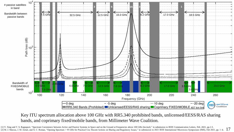
# passive satellites
in band
32.5 GHz 12.5 GHz7.5 GHzBandwidth between
passive bands15.0 GHz 8.2 GHz 17.0 GHz 18.5 GHz
3 5 15 3 1
Bandwidth of
FIXED/MOBILE
bands
5.0 GHz
7.5 GHz
2.45 GHz4.0 GHz 7.5 GHz 12.5 GHz 7.8 GHz 8.2 GHz 17.0 GHz 3.5 GHz
3.0 GHz
23.0 GHz
407 km link
Key ITU spectrum allocation above 100 GHz with RR5.340 prohibited bands, unlicensed/EESS/RAS sharing
bands, and coprimary fixed/mobile bands, from Millimeter Wave Coalition.
[1] Y. Xing and T. S. Rappaport, “Spectrum Coexistence between Active and Passive Systems in Space and on the Ground at Frequencies above 100 GHz (Invited),” in submission to IEEE Communication Letters, Feb. 2021, pp.1-5.
[2] M. J. Marcus, J. M. Jornet, and X. C. Roman, “Opening Spectrum > 95 GHz for Practical Use: Recent Actions on Sharing and Regulatory Issues,” in submission to 2021 IEEE International Microwave Symposium (IMS), Feb 2021, pp. 1–4. 17
NYU WIRELESS Research
18
Extensive indoor/outdoor propagation measurements at 142 GHz,
all data will be made available to NYU WIRELESS Industrial
Affiliates
20-178 m TR distances, 1 GHz RF bandwidth, 20 PDPs averaging,
53 TX-RX locations, LOS and NLOS, over 10, 000 PDPs in total
Urban Microcell, Small Cell, and Coordinated Multi-Point (CoMP)
Surrogate Satellite (Rooftop) Measurements for terrestrial
interference- foundational knowledge and new field of work
Channel modeling at frequencies above 100 GHz
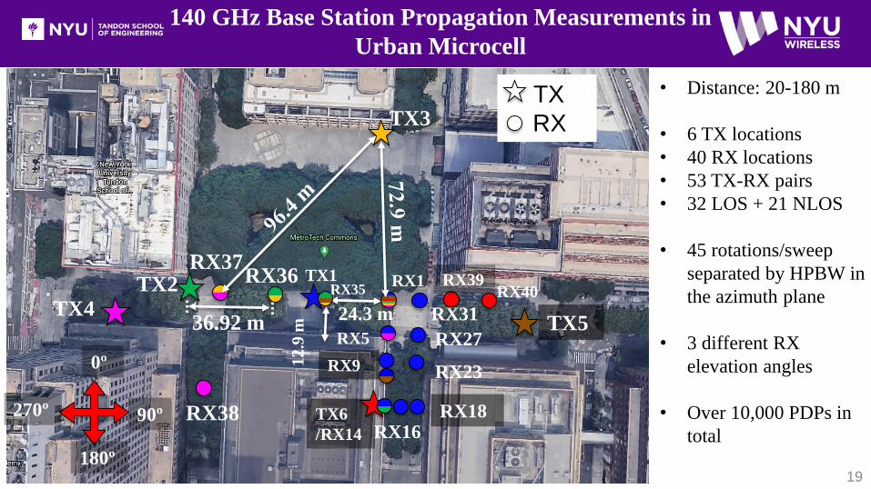
140 GHz Base Station Propagation Measurements in
Urban Microcell
19
24.3 m
TX1
12
.9 m
TX
RX
RX1TX2 RX36
RX5
RX9
TX6
/RX14 RX16RX18
RX23
RX27
RX31
TX3
RX37
36.92 m
0º
90º
180º
270º
TX4
RX38
TX5
RX39RX40RX35
• Distance: 20-180 m
• 6 TX locations
• 40 RX locations
• 53 TX-RX pairs
• 32 LOS + 21 NLOS
• 45 rotations/sweep
separated by HPBW in
the azimuth plane
• 3 different RX
elevation angles
• Over 10,000 PDPs in
total
20
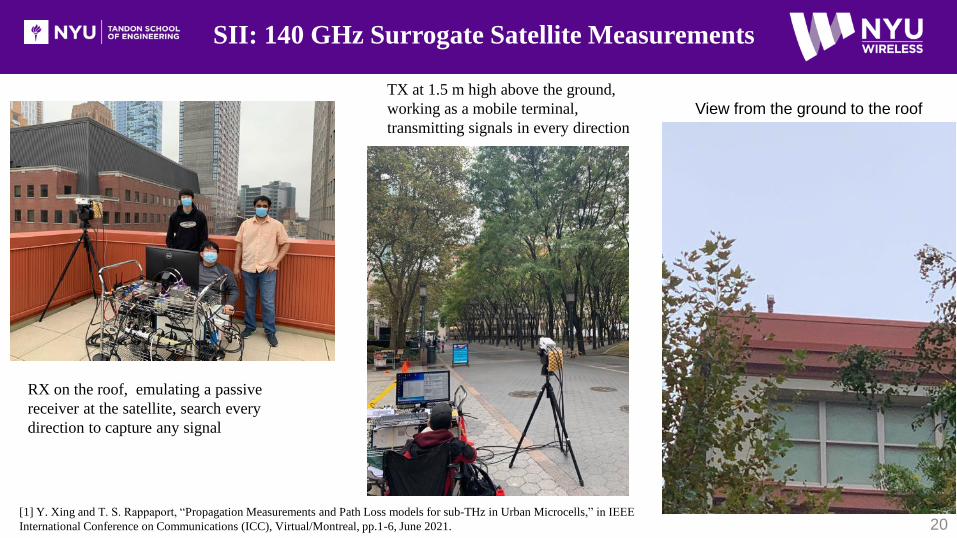
SII: 140 GHz Surrogate Satellite Measurements
RX on the roof, emulating a passive
receiver at the satellite, search every
direction to capture any signal
TX at 1.5 m high above the ground,
working as a mobile terminal,
transmitting signals in every direction
View from the ground to the roof
[1] Y. Xing and T. S. Rappaport, “Propagation Measurements and Path Loss models for sub-THz in Urban Microcells,” in IEEE
International Conference on Communications (ICC), Virtual/Montreal, pp.1-6, June 2021.

IRIS: Terahertz Study Project @ 140 GHz
21
Small-cell lamppost BS
(4.0 m above the ground)UE at 1.5 m ht
Microcell rooftop tall BS
(38.2 m above the ground)
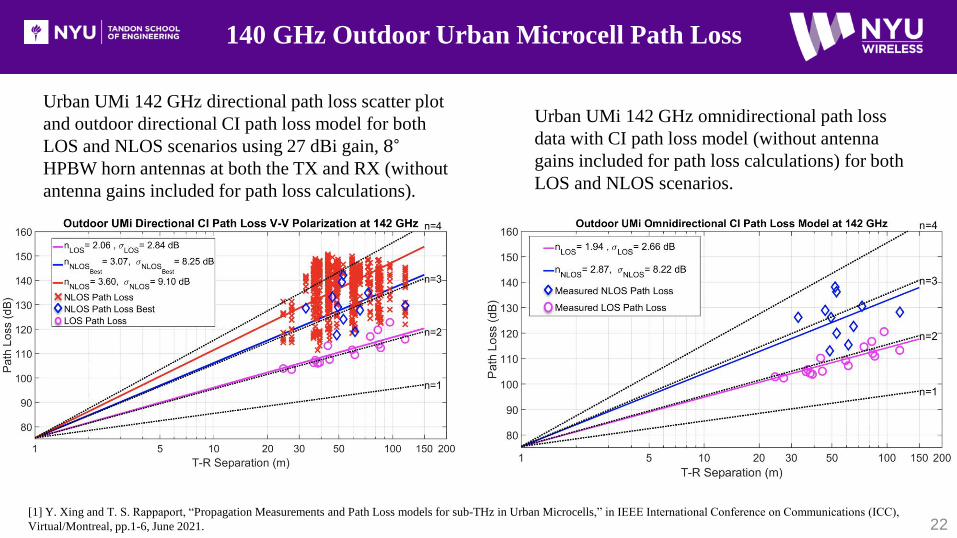
140 GHz Outdoor Urban Microcell Path Loss
22
Urban UMi 142 GHz directional path loss scatter plot
and outdoor directional CI path loss model for both
LOS and NLOS scenarios using 27 dBi gain, 8∘
HPBW horn antennas at both the TX and RX (without
antenna gains included for path loss calculations).
Urban UMi 142 GHz omnidirectional path loss
data with CI path loss model (without antenna
gains included for path loss calculations) for both
LOS and NLOS scenarios.
[1] Y. Xing and T. S. Rappaport, “Propagation Measurements and Path Loss models for sub-THz in Urban Microcells,” in IEEE International Conference on Communications (ICC),
Virtual/Montreal, pp.1-6, June 2021.

140 GHz Base Station Propagation Measurements in
Urban Microcell
23
Lampposts and trees Concrete building corners Glass wall/window Marble pillars Marble walls and glass walls
Trees Pedestrians Concrete pillars with corridors Trees and foliageBench and lampposts with
holiday cover
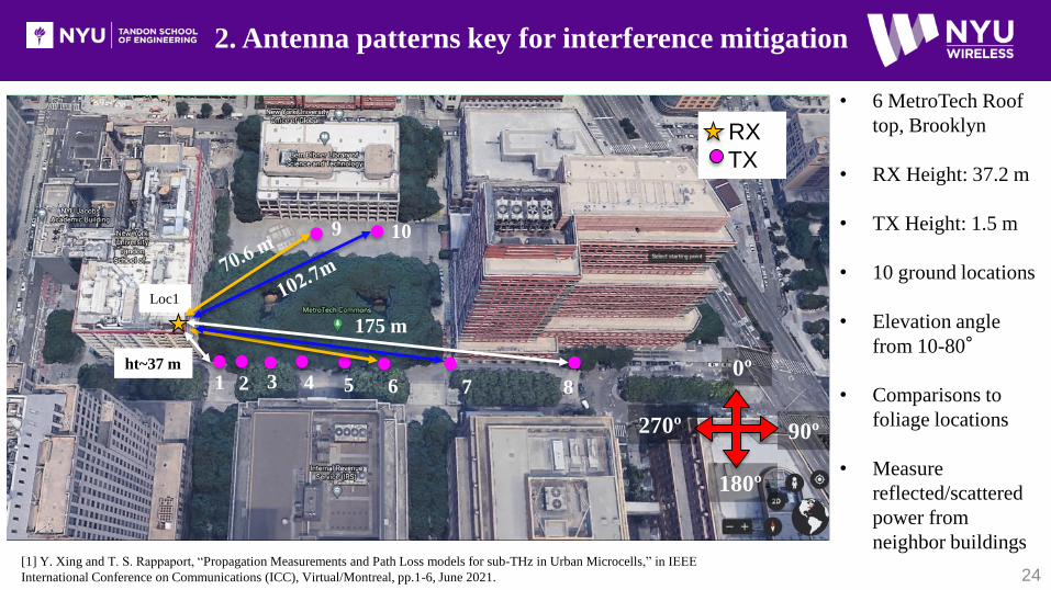
2. Antenna patterns key for interference mitigation
24
Loc1
ht~37 m
175 m
• 6 MetroTech Roof
top, Brooklyn
• RX Height: 37.2 m
• TX Height: 1.5 m
• 10 ground locations
• Elevation angle
from 10-80°
• Comparisons to
foliage locations
• Measure
reflected/scattered
power from
neighbor buildings
1 2 3 4 5 6 7 8
9 10
RX
TX
0º
90º
180º
270º
[1] Y. Xing and T. S. Rappaport, “Propagation Measurements and Path Loss models for sub-THz in Urban Microcells,” in IEEE
International Conference on Communications (ICC), Virtual/Montreal, pp.1-6, June 2021.
25
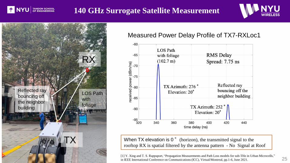
140 GHz Surrogate Satellite Measurement
TX
RX
LOS Path
with
foliage
Reflected ray
bouncing off
the neighbor
building
Measured Power Delay Profile of TX7-RXLoc1
When TX elevation is 0°(horizon), the transmitted signal to the
rooftop RX is spatial filtered by the antenna pattern - No Signal at Roof
[1] Y. Xing and T. S. Rappaport, “Propagation Measurements and Path Loss models for sub-THz in Urban Microcells,”
in IEEE International Conference on Communications (ICC), Virtual/Montreal, pp.1-6, June 2021.
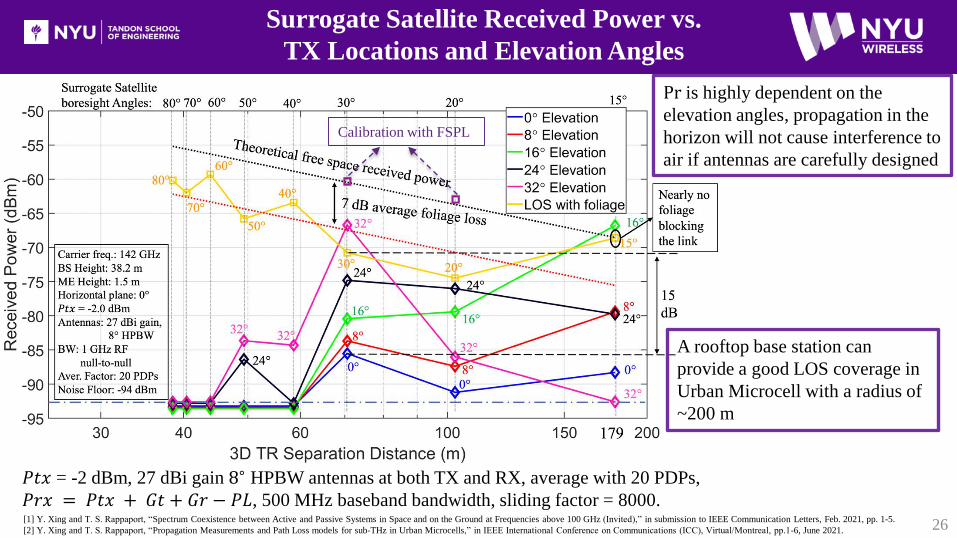
26
A rooftop base station can
provide a good LOS coverage in
Urban Microcell with a radius of
~200 m
Pr is highly dependent on the
elevation angles, propagation in the
horizon will not cause interference to
air if antennas are carefully designed
Surrogate Satellite Received Power vs.
TX Locations and Elevation Angles
𝑃𝑡𝑥 = -2 dBm, 27 dBi gain 8∘ HPBW antennas at both TX and RX, average with 20 PDPs,
𝑃𝑟𝑥 = 𝑃𝑡𝑥 + 𝐺𝑡 + 𝐺𝑟 − 𝑃𝐿, 500 MHz baseband bandwidth, sliding factor = 8000.
Calibration with FSPL
[1] Y. Xing and T. S. Rappaport, “Spectrum Coexistence between Active and Passive Systems in Space and on the Ground at Frequencies above 100 GHz (Invited),” in submission to IEEE Communication Letters, Feb. 2021, pp. 1-5.
[2] Y. Xing and T. S. Rappaport, “Propagation Measurements and Path Loss models for sub-THz in Urban Microcells,” in IEEE International Conference on Communications (ICC), Virtual/Montreal, pp.1-6, June 2021.
27
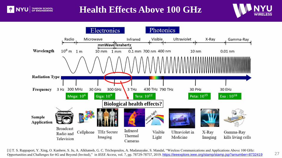
Health Effects Above 100 GHz
[1] T. S. Rappaport, Y. Xing, O. Kanhere, S. Ju, A. Alkhateeb, G. C. Trichopoulos, A. Madanayake, S. Mandal, “Wireless Communications and Applications Above 100 GHz:
Opportunities and Challenges for 6G and Beyond (Invited),” in IEEE Access, vol. 7, pp. 78729-78757, 2019. https://ieeexplore.ieee.org/stamp/stamp.jsp?arnumber=8732419
Biological health effects?
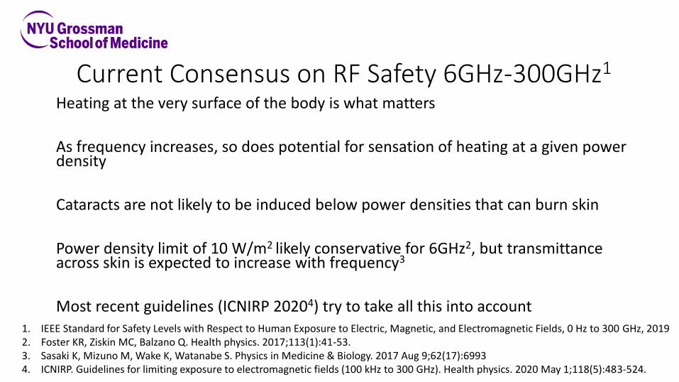
Current Consensus on RF Safety 6GHz-300GHz1
Heating at the very surface of the body is what matters
As frequency increases, so does potential for sensation of heating at a given power density
Cataracts are not likely to be induced below power densities that can burn skin
Power density limit of 10 W/m2 likely conservative for 6GHz2, but transmittance across skin is expected to increase with frequency3
Most recent guidelines (ICNIRP 20204) try to take all this into account1. IEEE Standard for Safety Levels with Respect to Human Exposure to Electric, Magnetic, and Electromagnetic Fields, 0 Hz to 300 GHz, 20192. Foster KR, Ziskin MC, Balzano Q. Health physics. 2017;113(1):41-53.3. Sasaki K, Mizuno M, Wake K, Watanabe S. Physics in Medicine & Biology. 2017 Aug 9;62(17):69934. ICNIRP. Guidelines for limiting exposure to electromagnetic fields (100 kHz to 300 GHz). Health physics. 2020 May 1;118(5):483-524.

ICNIRP. Guidelines for limiting exposure to electromagnetic fields (100 kHz to 300 GHz). Health physics. 2020 May 1;118(5):483-524.
Newly-published ICNIRP reference levels for time-averaged general public exposures of > 6 minutes, including
both whole-body exposure (solid lines) and new local exposures (dash-dot-dash lines). At frequencies from 100
GHz (100,000 MHz) to 300 GHz (300,000 MHz), local power density exposures, defined as averaged over any
1cm2, can exceed whole-body average exposures by a factor of 2.43 at 100Ghz to a factor of 2 at 300GHz.
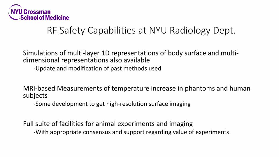
RF Safety Capabilities at NYU Radiology Dept.
Simulations of multi-layer 1D representations of body surface and multi-dimensional representations also available
-Update and modification of past methods used
MRI-based Measurements of temperature increase in phantoms and human subjects
-Some development to get high-resolution surface imaging
Full suite of facilities for animal experiments and imaging -With appropriate consensus and support regarding value of experiments

“Safe for Generations to Come”Wu, Rappaport, Collins; IEEE Microwave Magazine, March 2015 pp. 56-84
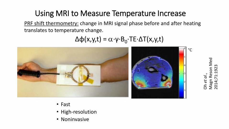
Using MRI to Measure Temperature Increase
Oh
et
al.,
Mag
nR
eso
nM
ed2
01
4;7
1:1
92
3
Δφ(x,y,t) = a·γ·B0·TE·ΔT(x,y,t)
PRF shift thermometry: change in MRI signal phase before and after heating translates to temperature change.
• Fast
• High-resolution
• Noninvasive
°C
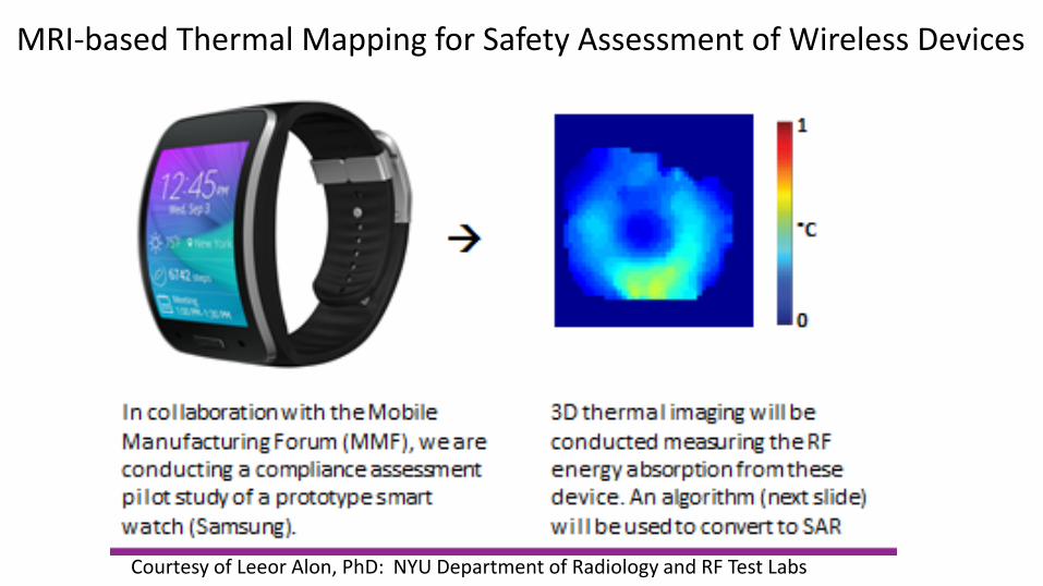
Courtesy of Leeor Alon, PhD: NYU Department of Radiology and RF Test Labs
MRI-based Thermal Mapping for Safety Assessment of Wireless Devices
C
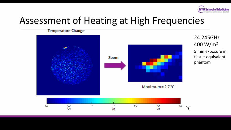
24.245GHz400 W/m2
Assessment of Heating at High Frequencies
5 min exposure in tissue-equivalent phantom
Animal Imaging & Monitoring Capabilities at NYU
•Methods for monitoring and analyzing differences in behavior and appetite with built-in cameras and scales
Dr. Adam Mar
• 3 micro-MRI systems•Micro CT/PET system• 6 Bioluminescence and Flourescence optical scanners• 4 high-frequency biomicroscopy ultrasound scanners
Dr. Youssef Wadghiri

Standard Mouse and Rat “Cages” at NYU
Rat
Mouse

Results and Conclusions
37
• 5G has seen enormous progress since the “It Will Work!” paper in 2013• Global rollouts: engineers and technicians learning about mmWave directional channels
• Governments are creating spectrum opportunities
• FCC opened up frequencies above 95 GHz., others, too
• NYU WIRELESS needs to lead above 100 GHz
• 1 Early work shows clear sailing channels up to 800 GHz!
• 2. Interference Mitigation for mobile, fixed, earth, satellite (antennas, ICs, DSP)
2a. Protection of astronomy and passive sensors critical – OOBE known/managed
• 3. Health Effects, heating primarily, but also non thermal need to be studied


