Download - Mini ProjecAndroid Controlled SwitchBoard

8/19/2019 Mini ProjecAndroid Controlled SwitchBoard
http://slidepdf.com/reader/full/mini-projecandroid-controlled-switchboard 1/59
Android Switchboard- Mini Project Report
Introduction
Ever since we invented electricity, we have been using switch
boards. Except certain changes in form factor, switches used for domestic
applications have stayed pretty much the same for the last century. Their
inherent disadvantage is that the operator has to manually turn the switch
on and off. But with the advent of new technology like Bluetooth
communication and Smart Phones, we can now tackle this disadvantage
and we can make Smart Switch Boards!.
Through our Pro"ect, we intent to tackle this problem by
making a switch board that can be controlled using an #ndroid mobile
phone. $or this, we intent to use the Bluetooth connectivity present in
almost all of the commercially available android phones. %e will be
using a Bluetooth to Serial module &'( )*+ to interface the phone and the
switch board. %e designed this system in such a way that it can be
integrated into existing switch boards as an addon and do not re-uire
ma"or overhauls of the wiring in the house.
The system has two parts one is the switchboard part and the other
is an android application. The switchboard part goes inside the
Switchboard. The android application is used to control the system using
an android phone.
Department of Instrumentation, CUSATPage 1
8/19/2019 Mini ProjecAndroid Controlled SwitchBoard
http://slidepdf.com/reader/full/mini-projecandroid-controlled-switchboard 2/59
Android Switchboard- Mini Project Report
Motivation and Product Design
%hile we were hunting ideas for the mini pro"ect, the most
important thing we had in mind was that whatever we build should have
immediate practical applications. %e wanted our pro"ect to solve a
common problem faced by the society. Since switchboards were present
everywhere and since they needed to be operated manually, we decided to
automate the system. oing so would increase the convenience for people
and would be of immense importance to elderly people and people
suffering from disabilities.
The three elements of design are/
• $unction
• #esthetics
• Ergonomics
%e have designed the product by keeping in mind all the above factors.
%e believe that this system will make a huge difference in our current
and future lives. %e are also excited about the future aspects and possible
expansions of our pro"ect.
2.Block Diagram
Department of Instrumentation, CUSATPage 2

8/19/2019 Mini ProjecAndroid Controlled SwitchBoard
http://slidepdf.com/reader/full/mini-projecandroid-controlled-switchboard 3/59
Android Switchboard- Mini Project Report
The goal of this pro"ect is to control a switch board from an
android phone. $or this we are using Bluetooth communication. The
system has two parts, a circuit that goes inside the switchboard and an
#ndroid app.
Figure 1:- Basic Block Diagram
Switchboard section
The switchboard section of the system contains a circuit board which has
Bluetooth communication capability.
Android Application
Department of Instrumentation, CUSATPage 3
Android
Application
Bluetooth
Communicat
Switchboard
Add-on
Circuit
HC 05
Bluetooth
Module
Serial Co!
Switches Microcontro
ller
Relays

8/19/2019 Mini ProjecAndroid Controlled SwitchBoard
http://slidepdf.com/reader/full/mini-projecandroid-controlled-switchboard 4/59
Android Switchboard- Mini Project Report
The android application pushes data to the Bluetooth client to transmit it
to the switch board. The data is collected by means of software switches
on a 0raphical user interface on the app.
Fig! " Block Diagram o# Android Application
Department of Instrumentation, CUSATPage "
#$%
ASC%%
Bluetooth
Client
1 B&te 'ata
Bluetooth
Mode
8/19/2019 Mini ProjecAndroid Controlled SwitchBoard
http://slidepdf.com/reader/full/mini-projecandroid-controlled-switchboard 5/59
Android Switchboard- Mini Project Report
".Block Diagram Description
Microcontroller
The microcontroller we choose for the system was the #tmel 12S*3. The
#T12(3)*4is a lowpower, highperformance (56S1bit
microcomputer with 17 bytes of $lash programmable and erasable read
only memory &PE865+. The device is manufactured using #tmel9s high
density non volatile memory technology and is compatible with the
industrystandard 1)(*4 and 1)(*3 instruction set and pinout. The on
chip $lash allows the program memory to be reprogrammed in system or
by a conventional non volatile memory programmer. :t is a stand ; alone
high ; performance single chip computer intended for use in sophisticated
realtime applications such as instrumentation, industrial control and
intelligent computer peripherals. :t provides the hardware features,
architectural enhancements and new instructions that make it a powerful
and cost effective device.
Switches
The switches we use for the system are the standard household switches.
The switches must be Single pole Single Throw &SPST+ Switches. :t is a
basic on<off switch that turns a single circuit on or off. #n SPST switch
has two terminals/ one for the input and one for the output. SPT &single
Department of Instrumentation, CUSATPage 5
8/19/2019 Mini ProjecAndroid Controlled SwitchBoard
http://slidepdf.com/reader/full/mini-projecandroid-controlled-switchboard 6/59
Android Switchboard- Mini Project Report
pole, double throw+/ #n SPT switch routes one input circuit to one of
two output circuits.
$ela%s
# relay is an electrically operated switch. 5any relays use an
electromagnet to mechanically operate a switch, but other operating
principles are also used, such as solidstate relays. 8elays are used where
it is necessary to control a circuit by a lowpower signal &with complete
electrical isolation between control and controlled circuits+, or where
several circuits must be controlled by one signal. The first relays were
used in long distance telegraph circuits as amplifiers/ they repeated the
signal coming in from one circuit and retransmitted it on another circuit.
8elays were used extensively in telephone exchanges and early
computers to perform logical operations.
Bluetooth Module
The device that we use for communication with the android phone is a
Bluetooth to serial module called '( )*. The '( )* receives and
transmits serial data as #S(:: data i.e. 4 Byte data. The device uses TT=
logic levels and has a default baud rate of 2>))bps.
&he '(I
Department of Instrumentation, CUSATPage (
8/19/2019 Mini ProjecAndroid Controlled SwitchBoard
http://slidepdf.com/reader/full/mini-projecandroid-controlled-switchboard 7/59
Android Switchboard- Mini Project Report
The graphical user interface of the android application uses software
switches to interact with the user and then relay that data back to the
controller through the Bluetooth client.
Bluetooth )lient and Bluetooth Modem
The Bluetooth client and Bluetooth modem present inside the android
phone can be used to sent the collected data to the controller by properly
configuring it. The use of high level languages to program the app makes
it easy to code the application.
Department of Instrumentation, CUSATPage )

8/19/2019 Mini ProjecAndroid Controlled SwitchBoard
http://slidepdf.com/reader/full/mini-projecandroid-controlled-switchboard 8/59
Android Switchboard- Mini Project Report
*. )ircuit Diagram
The circuit diagram for the Switch board side circuit is as shown below/
Fig 4:- Circuit Diagram
Department of Instrumentation, CUSATPage *

8/19/2019 Mini ProjecAndroid Controlled SwitchBoard
http://slidepdf.com/reader/full/mini-projecandroid-controlled-switchboard 9/59
Android Switchboard- Mini Project Report
+. Dc Power Suppl%
Fig 5:- DC Power Supply
These form an important e-uipment of any Electronics laboratory. Power
supplies are essential for the testing and implementation of any useful
electronic circuit. :f power supplies are not available then the only way to
provide power to a circuit is the battery. $or longterm use and fre-uent
manipulation these are not feasible. 5ore over these are not as flexible as
modern day power supplies. They do not provide for overload protection
and thermal protection.
Department of Instrumentation, CUSATPage +

8/19/2019 Mini ProjecAndroid Controlled SwitchBoard
http://slidepdf.com/reader/full/mini-projecandroid-controlled-switchboard 10/59
Android Switchboard- Mini Project Report
The following units form the backbone of any modern day power supply
• $ull wave bridge rectifier
• $ilter circuit
• ?oltage regulator
:n the case if modern power supplies, the re-uired power is derived from
the #( mains. $or this at first the 3@)?<*) 'A is step down using a step
down transformer. Then The #( voltage is converted to ( using a
rectifier circuit. The bridge rectifier is considered the apt choice since it
avoids the centertapped transformer. The ripples from the rectifiers
output are removed by filtering. The filter can be any of the following/
4. = filter
3. ( filter
@. =( filter
. (8( filter
#nd we use capacitive filtering.
The function of the voltage regulator is to provide a stable ( voltage for
powering other electronic circuits. The voltage regulator must be capable
of providing substantial output current. They must provide a constant
voltage regardless of changes in load current, temperature, and #( line
voltage. #lthough voltage regulators can be designed using opamps, it is
-uicker and easier to use :( ?oltage regulators. $urthermore, :( voltage
Department of Instrumentation, CUSATPage 10

8/19/2019 Mini ProjecAndroid Controlled SwitchBoard
http://slidepdf.com/reader/full/mini-projecandroid-controlled-switchboard 11/59
Android Switchboard- Mini Project Report
regulators are versatile and relatively inexpensive and are available with
features such as programmable output, current < voltage boosting, internal
short ;circuit current limiting, thermal shut down, and floating operation
for high voltage applications. ?oltage regulator may be classified as/
• Series 8egulator
• Switching 8egulator
Series regulators use a power transistor connected in series between the
unregulated ( input and the load. The output voltage is controlled by
the continuous voltage droptaking place across the series pass transistor.
Since the transistor conducts in the active or the linear region, these
regulators are also called linear regulators. =inear regulators may have
fixed or variable output voltages and could be positive or negative.
?oltage regulators such as the C1DD series and the :( C3@ are commonly
used. Switching regulators operate the power transistor as a '$ on<off
switch, so that the power transistor does not conduct current continuously.
This gives an improve efficiency over the series regulator. The :( C3@ can
be used as a switching regulator too.
%ith the advent of microelectronics, it is now possible to
incorporate the complete circuit of a voltage regulator on a single
monolithic silicon chip. These provide for high reliability, low cost,
Department of Instrumentation, CUSATPage 11

8/19/2019 Mini ProjecAndroid Controlled SwitchBoard
http://slidepdf.com/reader/full/mini-projecandroid-controlled-switchboard 12/59
Android Switchboard- Mini Project Report
reduced siAe and excellent performance. The C1DD, C2DD families and
:(C3@ are good examples of monolithic generalpurpose regulators. 'ere
we use the positive voltage regulators C1DD series.
78xx Series
The C1DD series of regulators are @ terminal, positive fixed voltage
regulators. There are C voltage options available like/ *?, >?, 1?, 43?,
4*?, 41? and 3?. The C2DD series are negative fixed voltage
regulators. These regulators are available in two types of packages/
4. 5etal Package &T6@+
3. Plastic Package &T633)+
,. Microcontroller
The microcontroller is programmed to read the serial data coming out of
the '( )* and turn the relays on or off according to the received data.
The #T12S*3 is a typical 1)*4 microcontroller manufactured by
#tmel.12S*3 has different ports, each one having 1 :nput<output lines
providing a total of @3 :<6 lines. Those ports can be used to output #T#
and orders do other devices, or to read the state of a sensor, or a switch.
5ost of the ports of the 12S*3 have dual function meaning that they can
be used for two different functions/ the fist one is to perform input<output
Department of Instrumentation, CUSATPage 12

8/19/2019 Mini ProjecAndroid Controlled SwitchBoard
http://slidepdf.com/reader/full/mini-projecandroid-controlled-switchboard 13/59
Android Switchboard- Mini Project Report
operations and the second one is used to implement special features of the
microcontroller like counting external pulses, interrupting the execution
of the program according to external events, performing serial data
transfer or connecting the chip to a computer to update the software.
Fig 6:- Block diagram of microcotroller
Department of Instrumentation, CUSATPage 13
8/19/2019 Mini ProjecAndroid Controlled SwitchBoard
http://slidepdf.com/reader/full/mini-projecandroid-controlled-switchboard 14/59
Android Switchboard- Mini Project Report
The main features include/
1kb of insystem programmable flash memory
.)v to *.*v operating range
$ully static operation/ ) 'A to @@ 5'A
Threelevel program memory lock
3*> x 1 bit internal 8#5
@3 Programmable :<6 lines
Three 4> bit timer<counters
1 interrupt sources
$ull duplex F#8T serial channel
=ow power :dle and power down 5odes
:nterrupt 8ecovery from Power down 5ode
%atchdog Timer
ual ata pointer
Power off flag
Department of Instrumentation, CUSATPage 1"

8/19/2019 Mini ProjecAndroid Controlled SwitchBoard
http://slidepdf.com/reader/full/mini-projecandroid-controlled-switchboard 15/59
Android Switchboard- Mini Project Report
Fig !:- Pi out of "#S5$
PI- DS)$IP&I/-
Vss :(ircuit ground potential
Vcc :G*? power supply during operation, programming and verification.
Port ‘O’ :Port H6I is an 1bit open drain bidirectional :<6 port. :t is also
the multiplexed low order address and data bus when using external
memory. :t is used for data output and output during programming and
verification. Port 6 can sink<source two TT= loads.
Department of Instrumentation, CUSATPage 15

8/19/2019 Mini ProjecAndroid Controlled SwitchBoard
http://slidepdf.com/reader/full/mini-projecandroid-controlled-switchboard 16/59
Android Switchboard- Mini Project Report
Port 1 :Port 4 is an 1bit -uasitraditional :<6 port. :t also emits the low
order address byte during programming and verification. Port 4 can
sink<source one TT= =oad.
Port 2 :Port 3 is an 1bit -uasibidirectional :<6 port. :t also emits the
high order address byte when accessing external memory. :t is used for
the highorder address and the control signals during programming and
verification. Port 3 can sink<source one TT= load.
Port 3 :Port @ is an 1bit -uasi bidirectional :<6 port. :t also contains the
interrupt, timer, serial port and 8 and %8 pins that are used by various
options. The output batch corresponding to a secondary function must be
programmed to a one &4+ for that function to operate. Port @ can
sink<source one TT= load. The secondary functions are assigned to the
pins of port @, as follows.
R!"data #P3$%&:Serial PortIs receiver data input &asynchronous+ or data
input<output &synchronous+.
T!"'loc( #P3$1& Serial ports transmitts data output &asynchronous+ or
clock output &synchronous+.
)*TO #P3$2&::nterrupt 6 input or gate control input for counter ).
)*T) #P3$3& ::nterrupt 4 input or gate control input for counter 4.
T% #P3$+&::nput to counter ).
Department of Instrumentation, CUSATPage 1(

8/19/2019 Mini ProjecAndroid Controlled SwitchBoard
http://slidepdf.com/reader/full/mini-projecandroid-controlled-switchboard 17/59
Android Switchboard- Mini Project Report
T1 #P3$,&::nput to counter 4.
-R #P3$.&:The write control signal batches the data byte from port ) into
the External ata 5emory to port ).
RST"VP! :# low to high transition on this pin &at approximately @?+
resets the 1)*4. :f ?P is held within its space &approximately G*?+,
while ?cc drops below spec, ?P will provide stand by power to the
8#5. %hen ?P is low, the 8#5Is current is drawn from ?cc. # small
internal resistor permits power on reset using only a capacitor connected
to ?cc.
/0"PRO:Provides #ddress =atch Enable output used for latching the
address into external memory during normal operation. 8eceives the
program pulse input during EP865 programming.
PS*: The program store enable output is a control signal that enables
the external program memory to the bus during normal fetch operations.
/"V!!: %hen held at a TT= high level, the 1)*4 executes instructions
from the internal 865<EP865 when the P( is less than )2>. %hen
held at a TT= low level, the 1)*4 fetches all instructions from external
program memory. The pin also receives the 34? EP865 programming
supply voltage.
Department of Instrumentation, CUSATPage 1)

8/19/2019 Mini ProjecAndroid Controlled SwitchBoard
http://slidepdf.com/reader/full/mini-projecandroid-controlled-switchboard 18/59
Android Switchboard- Mini Project Report
T/01::nput to the oscillators high gain amplifier. # crystal or external
source can be used.
/PP0)'/T)O*S O 4)'RO'O*TRO00R
4+ 'andheld instruments
a+ Pagers
b+ Electronic plan meter
c+ =evel meter
d+ :( Tester
3+ Peripheral evices
a+ 7eyboard controller
b+ 5odem
c+ Printer buffer
@+ Stand#lone devices
a+ (olor copier
b+ Electronic typewriter
c+ (able T? terminal
+ :nstrumental Sub$unctions
a+ igital oscilloscope
b+ edicated front panel
c+ 5icrowave computer
*+#utomotive application
Department of Instrumentation, CUSATPage 1*
8/19/2019 Mini ProjecAndroid Controlled SwitchBoard
http://slidepdf.com/reader/full/mini-projecandroid-controlled-switchboard 19/59
Android Switchboard- Mini Project Report
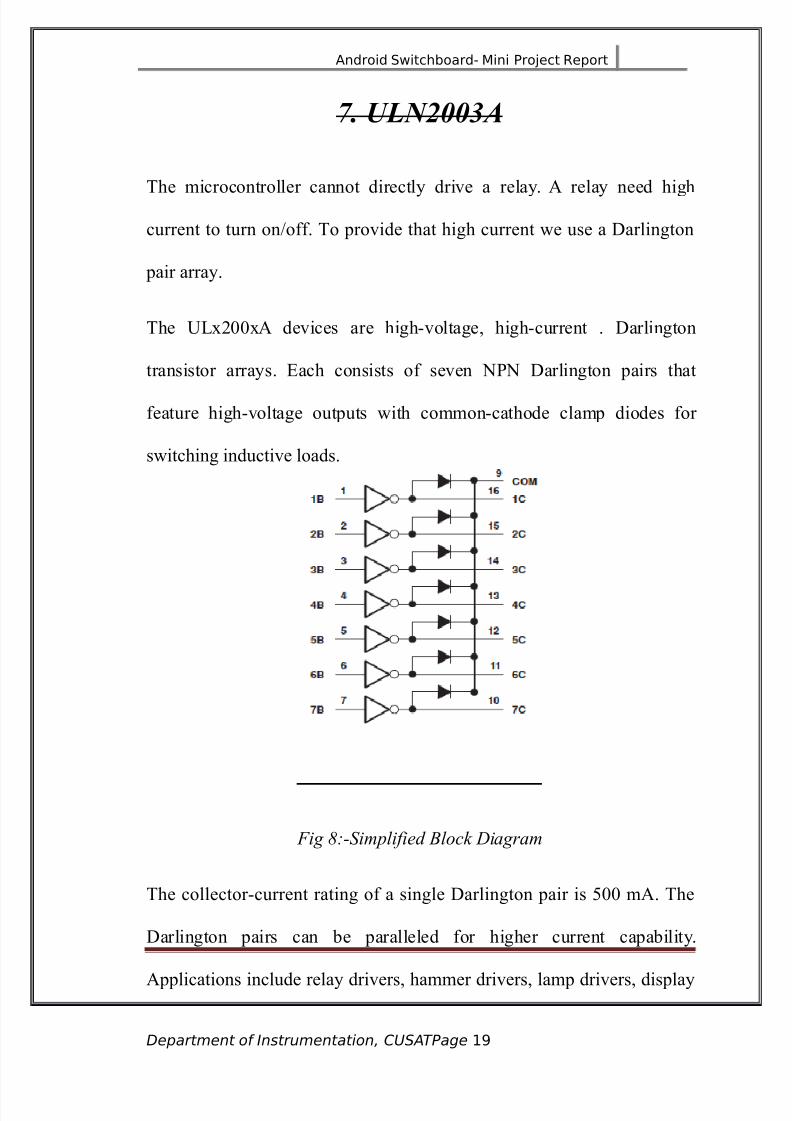
0. (1-2"A
The microcontroller cannot directly drive a relay. # relay need high
current to turn on<off. To provide that high current we use a arlington
pair array.
The F=x3))x# devices are highvoltage, highcurrent . arlington
transistor arrays. Each consists of seven JPJ arlington pairs that
feature highvoltage outputs with commoncathode clamp diodes for
switching inductive loads.
Fig ":-Simplified Block Diagram
The collectorcurrent rating of a single arlington pair is *)) m#. The
arlington pairs can be paralleled for higher current capability.
#pplications include relay drivers, hammer drivers, lamp drivers, display
Department of Instrumentation, CUSATPage 1+

8/19/2019 Mini ProjecAndroid Controlled SwitchBoard
http://slidepdf.com/reader/full/mini-projecandroid-controlled-switchboard 20/59
Android Switchboard- Mini Project Report
drivers &=E and gas discharge+, line drivers, and logic buffers. $or 4))
? &otherwise interchangeable+ versions of the F=x3))@# devices, see the
S=8S)3@ data sheet for the SJC*>1 and SJC*>2 devices. The
F=J3))3# device is designed specifically for use with 4? to 3*?
P56S devices. Each input of this device has a Kener diode and resistor in
series to control the input current to a safe limit. The F=x3))@# devices
have a 3.CkL series base resistor for each arlington pair for operation
directly with TT= or *? (56S devices.
3. 4) + Bluetooth Module
:t is a Bluetooth module that is widely used with 5icrocontroller to
enable Bluetooth communication. This module cam be interfaced using
the F#8T in 1)*4 microcontroller where the data are transmitted in the
form of packets. The pins TD and 8D pin of the '( )* form the path for
data transmission and reception. These TD pin of '()* must be
connected to the 8D pin of 1)*4 and vice versa.
Department of Instrumentation, CUSATPage 20

8/19/2019 Mini ProjecAndroid Controlled SwitchBoard
http://slidepdf.com/reader/full/mini-projecandroid-controlled-switchboard 21/59
Android Switchboard- Mini Project Report
Fig #:- %C &5 Bluetoot' (odule
'()* module is an easy to use Bluetooth SPP &Serial Port Protocol+
module, designed for transparent wireless serial connection setup.
Serial port Bluetooth module is fully -ualified Bluetooth ?3.)GE8
&Enhanced ata 8ate+ @5bps 5odulation with complete 3.0'A radio
transceiver and baseband. :t uses (S8 Bluecore )External single chip
Bluetooth system with (56S technology and with #$'&#daptive
$re-uency 'opping $eature+
5ard6are eatures
• Typical 1)dBm sensitivity
• Fp to GdBm 8$ transmit power
• =ow Power 4.1? 6peration ,4.1 to @.>? :<6
• P:6 control
•
F#8T interface with programmable baud rate
Department of Instrumentation, CUSATPage 21

8/19/2019 Mini ProjecAndroid Controlled SwitchBoard
http://slidepdf.com/reader/full/mini-projecandroid-controlled-switchboard 22/59
Android Switchboard- Mini Project Report
• %ith integrated antenna
• %ith edge connector
Soft6are eatures
• efault Baud rate/ @1)), ata bits/1, Stop bit/4,Parity/Jo parity, ata control/ has.
Supported baud rate/ 2>)),423)),@1)),*C>)),44*3)),3@))),>)1)).
• 0iven a rising pulse in P:6), device will be disconnected.
• Status instruction port P:64/ lowdisconnected, highconnectedM
• P:64) and P:644 can be connected to red and blue led separately. %hen master and slave
are paired, red and blue led blinks 4time<3s in interval, while disconnected only blue led blinks 3times<s.
• #utoconnect to the last device on power as default.
• Permit pairing device to connect as default.
• #utopairing P:J(6E/!))))! as default
• #utoreconnect in @) min when disconnected as a result of beyond the range of connection.
Department of Instrumentation, CUSATPage 22
8/19/2019 Mini ProjecAndroid Controlled SwitchBoard
http://slidepdf.com/reader/full/mini-projecandroid-controlled-switchboard 23/59
Android Switchboard- Mini Project Report
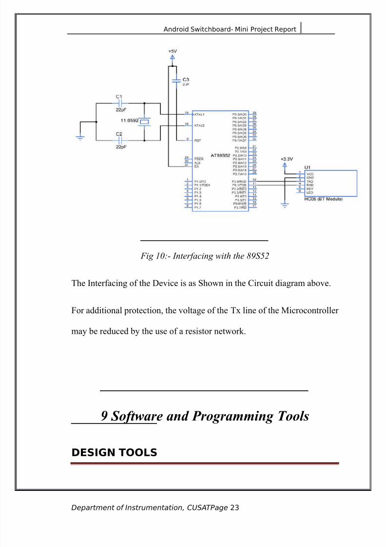
Fig 1&:- )terfacig wit' t'e "#S5$
The :nterfacing of the evice is as Shown in the (ircuit diagram above.
$or additional protection, the voltage of the Tx line of the 5icrocontroller
may be reduced by the use of a resistor network.
5 So#tware and Programming &ools
DESIGN !!"S
Department of Instrumentation, CUSATPage 23

8/19/2019 Mini ProjecAndroid Controlled SwitchBoard
http://slidepdf.com/reader/full/mini-projecandroid-controlled-switchboard 24/59
Android Switchboard- Mini Project Report
lectronic !esin /utomation #!/& Tools: %ith the advent of
powerful computing system and interactive software stages in the design
and development of an electronic circuit has undergone automation is
called E# tools. This tool helps us in such a way that we can draw the
circuit, list the functioning of the circuit in response to the best input in
assimilation software after successfully simulating the circuit. The
placing and routing software does the P(B artwork in the pro"ect. The
design automation tool used is EDP8ESS P(B, which includes
EDP8ESS S(' ; $or circuiting the diagram, create schematic and net
list.
EDP8ESS P(B ; $or creating the P(B artwork .
Programming Tools
,he prora wa. written and .iulated u.in Mi/roC
which i. a coplete %'! %t con.i.t. o a tet editor C
copiler and a .iulator to .iulate our code! ,he Mi/roC
PR4 or P%C i. a powerul eature- rich deelopent tool
or P%C icrocontroller.! %t i. de.ined to proide the
proraer with the ea.ie.t po..ible .olution to deelop
Department of Instrumentation, CUSATPage 2"
8/19/2019 Mini ProjecAndroid Controlled SwitchBoard
http://slidepdf.com/reader/full/mini-projecandroid-controlled-switchboard 25/59
Android Switchboard- Mini Project Report
application. or ebedded .&.te. without
coproi.in perorance or control!
eatures: 5ickro( P86 for P:( allows you to -uickly develop
and deploy complex applications
• %rite your ( source code using the built in code editor &(ode and
Parameter #ssistance, (ode $olding, Syntax 'ighlighting, #uto
(orrect (ode Templates, and more.+
• Fse included 5ikro( P86 for #T12c3)*4 and #T12s*3
microcontroller libraries to dramatically speed up the development/
data ac-uisition, memory, displays, conversations, communicationsetc.
• 5onitor your program structure, variables and functions in the
(ode Explorer.
• 0enerate commented, human readable assembly, and standard
'ED compatible with all programmers.
eatures: 5ickro( P86 for P:( allows you to -uickly develop
and deploy complex applications
• %rite your ( source code using the built in code editor &(ode and
Parameter #ssistance, (ode $olding, Syntax 'ighlighting, #uto
(orrect (ode Templates, and more.+
• Fse included 5ikro( P86 for #T12c3)*4 and #T12s*3
microcontroller libraries to dramatically speed up the development/
data ac-uisition, memory, displays, conversations, communications
etc.
• 5onitor your program structure, variables and functions in the
(ode Explorer.
• 0enerate commented, human readable assembly, and standard
'ED compatible with all programmers.
Department of Instrumentation, CUSATPage 25

8/19/2019 Mini ProjecAndroid Controlled SwitchBoard
http://slidepdf.com/reader/full/mini-projecandroid-controlled-switchboard 26/59
Android Switchboard- Mini Project Report
6 P)B Design
The P(B design starts right from the selection of the laminates .The two
main types of base laminate are epoxy glass and phenolic paper laminates
are generally used for simple circuits. Though it is very cheap and can
easily be drilled, phenolic paper has poor electrical characteristics and it
absorbs more moisture than epoxy glass. Epoxy glass has higher mechanical strength.
The important properties that have to be considered for selecting the P(B
substrate are the dielectric strength, insulation resistance, water
absorption property, coefficient of thermal expansion, shear strength,
hardness, dimensional stability etc.
4anufacturin Process
The steps involved in manufacture are
Department of Instrumentation, CUSATPage 2(

8/19/2019 Mini ProjecAndroid Controlled SwitchBoard
http://slidepdf.com/reader/full/mini-projecandroid-controlled-switchboard 27/59
Android Switchboard- Mini Project Report
a+ #rtwork preparation.
b+ 8esist preparation.
c+ 8esist application an fixing.
d+ #cid etches.
e+ (leaning and inspection.
f+ 8esist removal.
P'9 arication
The fabrication of P(B has basically of four steps.
a+ Preparing the P(B pattern.
b+ Transferring the pattern onto the P(B.
c+ eveloping the P(B.d+ $inishing ie+ drilling, cutting, smoothing, turning etc.
Pre;arin the P'9 ;attern
Pattern designing is the primary step in fabricating a P(B in this step, all
interconnection between the components in the given circuit are
converted into P(B tracks several factors such as positioning, the
diameter of holes, the area that each component would occupy, and thetype of end terminal should be considered.
Transferrin the P'9 Pattern
The copper side of the P(B should be thoroughly cleaned with the help
of alcoholic spirit or petrol must be completely free from dust and other
contaminants. The mirror image of the pattern must be carbon copied andto the laminate the complete pattern may now be made each resistant with
the screen printing technology.
!e<elo;in
:n this developing all excessive copper is removed from the board
and only the printed pattern is left behind. #bout 4))ml of tape water
should be heated to C* N ( and @).* grams of $e(l @ added to it, the
Department of Instrumentation, CUSATPage 2)

8/19/2019 Mini ProjecAndroid Controlled SwitchBoard
http://slidepdf.com/reader/full/mini-projecandroid-controlled-switchboard 28/59
Android Switchboard- Mini Project Report
mixture should be thoroughly stirred and a few drops of '(l may be
added to speed up the process.
The board with its copper side facing upward, should be placed in a
flat bottomed plastic tray and the a-ueous solution of $e(l3 poured in
the etching process would take ) to >) min to complete.
#fter etching the board it should be washed under running water
and then held against light .the printed pattern should be cleanly visible.
The paint should be removed with the help of thinner.
inishin Touches
#fter the etching is completed ,hole of suitable diameter should be
drilled, then the P(B may be tin plated using an ordinary @* %atts
soldering rod along with the solder core ,the copper side may be given a
coat of varnish to prevent oxidation.
!rillin
rills for P(B use usually come with either a set of collects of
various siAes or a @Oaw chuck. $or accuracy however @"aw chunks
aren9t brilliant and small drill below 4 mm from grooves in the "aws
preventing good grips.
Solderin
Begin the construction by soldering the resistors followed by the
capacitors and the =Es diodes and :( sockets. on9t try soldering an
:( directly unless you trust your skill in soldering. #ll components
should be soldered as shown in the figure. Jow connect the switch and
then solder<screw if on the P(B using multiple washers or spaces.
Department of Instrumentation, CUSATPage 2*
8/19/2019 Mini ProjecAndroid Controlled SwitchBoard
http://slidepdf.com/reader/full/mini-projecandroid-controlled-switchboard 29/59

8/19/2019 Mini ProjecAndroid Controlled SwitchBoard
http://slidepdf.com/reader/full/mini-projecandroid-controlled-switchboard 30/59
Android Switchboard- Mini Project Report
Fig 11:- *op copper layer
• (omponents =ayout/
Fig 1$:- Compoets +ayout
12 The Program
----------------------------------------------------------------------------------
---------------
Department of Instrumentation, CUSATPage 30

8/19/2019 Mini ProjecAndroid Controlled SwitchBoard
http://slidepdf.com/reader/full/mini-projecandroid-controlled-switchboard 31/59
Android Switchboard- Mini Project Report
includeQregx*4.hR
define mode P4C
<< global variables
unsigned char con,ipt,asM
unsigned int nbM
void modify&+M
void toggles&unsigned char d+M
void serialcomm&+M
void toggle&unsigned char s+M
<< main
void main&+
unsigned char a,bM
nbU)M
P4U)xffM
P)U)xffM
T'4U)xfdM
T56U)x3)M
T:U)M
T84U4M
S5)U)M
S54U4M
E#U4M
ESU4M
8EJU4M
P)CU)M
aUP4V)x4fM
Department of Instrumentation, CUSATPage 31

8/19/2019 Mini ProjecAndroid Controlled SwitchBoard
http://slidepdf.com/reader/full/mini-projecandroid-controlled-switchboard 32/59
Android Switchboard- Mini Project Report
bUP)V)xe)M
P)UaWbM
asUP4M
iptUP4V)x4fM
while&4+
if&modeUU)+
aUP4V)x4fM
bUP)V)xe)M
P)UaWbM
Xelse
modify&+M
X
X
X
void serialcomm&+ interrupt
conUSBF$M
nbU4M
8:U)M
returnM
X
void modify&+
if&nbUU4+
Department of Instrumentation, CUSATPage 32
8/19/2019 Mini ProjecAndroid Controlled SwitchBoard
http://slidepdf.com/reader/full/mini-projecandroid-controlled-switchboard 33/59
Android Switchboard- Mini Project Report
nbU)M
toggle&con+M
Xelse
if&iptYU&P4V)x4f++
asUP4M
toggles&P4+M
X
X
iptUasV)x4fM
returnM
X
void toggle&unsigned char s+
switch&s+
case )/ P))UZP))M
breakM
case 4/ P)4UZP)4M
breakM
case 3/ P)3UZP)3M
breakM
case @/ P)@UZP)@M
breakM
case / P)UZP)M
breakM
default / P)CUZP)CM
X
Department of Instrumentation, CUSATPage 33

8/19/2019 Mini ProjecAndroid Controlled SwitchBoard
http://slidepdf.com/reader/full/mini-projecandroid-controlled-switchboard 34/59
Android Switchboard- Mini Project Report
returnM
X
void toggles&unsigned char d+
unsigned char a,b,cM
aUd[iptM
bUP4V)xe)M
cUZaM
cUcVP4M
aUaVP4M
aUaWcM
aU)x4fVaM
P)UaWbM
returnM
X
<< End of Program
6" Android Application Development
The second part of the system is the #ndroid application. :n order to
develop the app, we used a development environment called 5:T #pp
Department of Instrumentation, CUSATPage 3"

8/19/2019 Mini ProjecAndroid Controlled SwitchBoard
http://slidepdf.com/reader/full/mini-projecandroid-controlled-switchboard 35/59
Android Switchboard- Mini Project Report
:nventor. :t is a "oint venture by 0oogle and 5assachusetts :nstitute of
Technology, FS#.
6ur devices such as mobile and P(9s need special applications known as
Bluetooth Terminal! to communicate with our microcontrollers viaBluetooth.
These applications are developed in such a way to send characters
through your device BT which was received by the BT module connected
with our controller. Even some apps offers some interactive 0F: buttons
which transmits specific characters with the press of each buttons. =ater
the received character can be processed in our code and force the
controller to perform tasks based on the received character. %e can use
the Bluetooth communication in two ways, either we can use it to receive
data from the (ontroller or control the system using our device
Bluetooth.
&he App Inventor
#pp :nventor for #ndroid is an opensource web application originally
provided by 0oogle, and now maintained by the 5assachusetts :nstitute
of Technology &5:T+.
:t allows newcomers to computer programming to create software
applications for the #ndroid operating system &6S+. :t uses a graphical
interface, very similar to Scratch and the Star=ogo TJ0 user interface,
which allows users to draganddrop visual ob"ects to create an
application that can run on #ndroid devices. :n creating #pp :nventor,
0oogle drew upon significant prior research in educational computing, as
well as work done within 0oogle on online development environments.
\4]
#pp :nventor and the pro"ects on which it is based are informed by
constructionist learning theories, which emphasiAes that programming
can be a vehicle for engaging powerful ideas through active learning. #s
such, it is part of an ongoing movement in computers and education that
began with the work of Seymour Papert and the 5:T =ogo 0roup in the
42>)s and has also manifested itself with 5itchel 8esnicks work on=ego 5indstorms and Star=ogo.
Department of Instrumentation, CUSATPage 35
8/19/2019 Mini ProjecAndroid Controlled SwitchBoard
http://slidepdf.com/reader/full/mini-projecandroid-controlled-switchboard 36/59
Android Switchboard- Mini Project Report
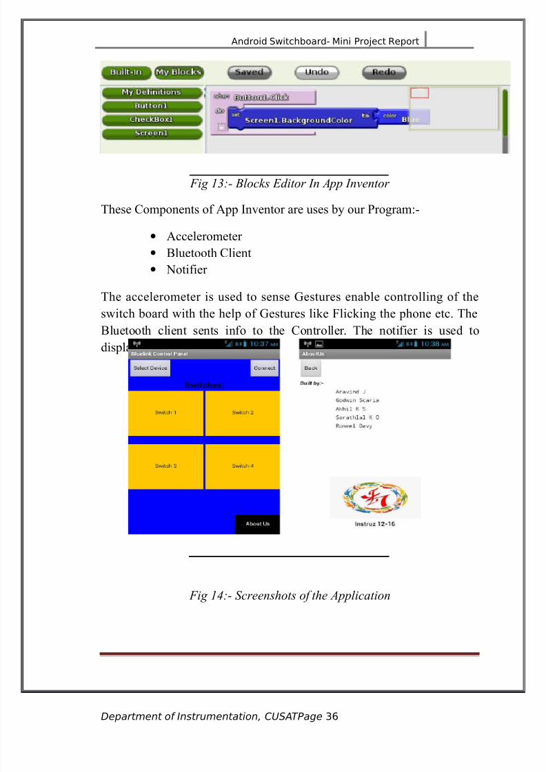
Fig 1,:- Blocks ditor ) .pp )/etor
These (omponents of #pp :nventor are uses by our Program/
• #ccelerometer
• Bluetooth (lient
• Jotifier
The accelerometer is used to sense 0estures enable controlling of the
switch board with the help of 0estures like $licking the phone etc. The
Bluetooth client sents info to the (ontroller. The notifier is used to
display error messages on screen.
Fig 14:- Screes'ots of t'e .pplicatio
Department of Instrumentation, CUSATPage 3(
8/19/2019 Mini ProjecAndroid Controlled SwitchBoard
http://slidepdf.com/reader/full/mini-projecandroid-controlled-switchboard 37/59
Android Switchboard- Mini Project Report
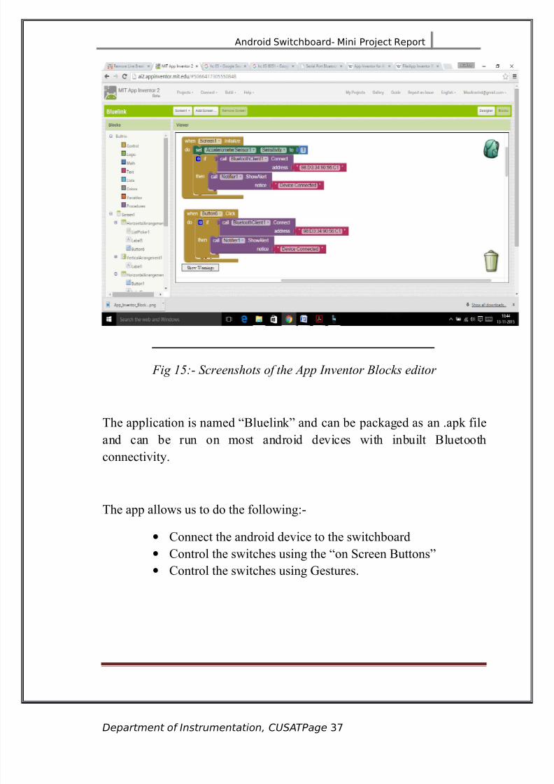
Fig 15:- Screes'ots of t'e .pp )/etor Blocks editor
The application is named Bluelink! and can be packaged as an .apk file
and can be run on most android devices with inbuilt Bluetooth
connectivity.
The app allows us to do the following/
• (onnect the android device to the switchboard
• (ontrol the switches using the on Screen Buttons!
• (ontrol the switches using 0estures.
Department of Instrumentation, CUSATPage 3)

8/19/2019 Mini ProjecAndroid Controlled SwitchBoard
http://slidepdf.com/reader/full/mini-projecandroid-controlled-switchboard 38/59
Android Switchboard- Mini Project Report
6* Applications
The system designed as part of this 5ini Pro"ect can be used for the
following applications/
4. 'ome #utomation Systems
3. %ireless 6peration of Switchboards using a android phone.
@. Fsing #ndroid phone to control 'ome #ppliances
. The system can help old and disabled people control their
home appliances with an android phone.
Department of Instrumentation, CUSATPage 3*
8/19/2019 Mini ProjecAndroid Controlled SwitchBoard
http://slidepdf.com/reader/full/mini-projecandroid-controlled-switchboard 39/59
Android Switchboard- Mini Project Report
6+ Merits and Demerits
5erits/
4. Easy to setup
3. Since android phones have become ubi-uitous, no separate
remote control is needed for different home appliances. They
can all be controlled using an android phone.
@. Fse of gesture recognition technology allows the system to
be controlled even by blind people.
emerits/
4. (an be use to control only one switchboard.
3. Bluetooth technology has a range of only 4) meters.
@. (annot yet control regulators of fans etc.
Department of Instrumentation, CUSATPage 3+
8/19/2019 Mini ProjecAndroid Controlled SwitchBoard
http://slidepdf.com/reader/full/mini-projecandroid-controlled-switchboard 40/59
Android Switchboard- Mini Project Report
6, Future Scope
The future scope of a system like this is a thousand times more exciting
than the current design. %ith the inevitable advent of the :nternet of
Things &:oT+, a connected switchboard could be controlled from
anywhere in the world. The complete control of the devices at our homes
can be done from an internet enabled device, placed anywhere in the
world.
*'e furt'er de/elopmets t'at ca 0e doe are:-
4. 8eplace Bluetooth with %i$i to get better range andfunctionality.
3. (onnect to the internet to enable :oT.
@. Jetwork a number of switchboards to make a complete
home automation system.
. :mprove the functionality of the android app to turn devices
on<off at specific times of the day with no user input etc..
Department of Instrumentation, CUSATPage "0

8/19/2019 Mini ProjecAndroid Controlled SwitchBoard
http://slidepdf.com/reader/full/mini-projecandroid-controlled-switchboard 41/59
Android Switchboard- Mini Project Report
60 )onclusion
The pro"ect was designed and implemented successfully and has proved
to be of immense practical applications. The system enables a person to
control the appliances connected to a switchboard using an #ndroid
Phone. The system can be very useful to old and physically challenged
people. The future scope of the system is aweinspiring and can be the
sub"ect of a larger pro"ect.
Department of Instrumentation, CUSATPage "1
8/19/2019 Mini ProjecAndroid Controlled SwitchBoard
http://slidepdf.com/reader/full/mini-projecandroid-controlled-switchboard 42/59
Android Switchboard- Mini Project Report
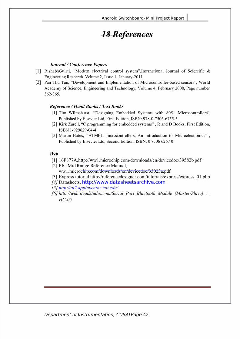
63 $e#erences
7ournal 8 )on#erence Papers
\4] 8ishabh0ulati, 5odern electrical control system!,:nternational Oournal of Scientific V
Engineering 8esearch, ?olume 3, :ssue 4, Oanuary3)44.
\3] Pan Thu Tun, evelopment and :mplementation of 5icrocontrollerbased sensors!, %orld
#cademy of Science, Engineering and Technology, ?olume , $ebruary 3))1, Page number
@>3@>*.
$e#erence 8 4and Books 8 &e9t Books
\4] Tim %ilmshurst, esigning Embedded Systems with 1)*4 5icrocontrollers!,
Published by Elsevier =td, $irst Edition, :SBJ/ 2C1)C*)>>C***\3] 7irk Kurell, ( programming for embedded systems! , 8 and Books, $irst Edition,
:SBJ 4232>32)
\@] 5artin Bates, #T5E= microcontrollers, #n introduction to 5icroelectronics! ,
Published by Elsevier =td, Second Edition, :SBJ/ ) C*)> >3>C )
:eb
\4] 4>$1CC#,http/<<ww4.microchip.com<downloads<en<devicedoc<@2*13b.pdf
\3] P:( 5id 8ange 8eference 5anual,
ww4.microchip.com<downloads<en<devicedoc<@@)[email protected]
\@] Express tutorial,http/<<referencedesigner.com<tutorials<express<express)4.php42 atasheets, http677www!data.heet.archie!co52 'ttp:33ai$appi/etormitedu3
62 'ttp:33wikiiteadstudiocom3SerialPortBluetoot'(odule(aster3Sla/e7:
%C-&5
Department of Instrumentation, CUSATPage "2

8/19/2019 Mini ProjecAndroid Controlled SwitchBoard
http://slidepdf.com/reader/full/mini-projecandroid-controlled-switchboard 43/59
Android Switchboard- Mini Project Report
Department of Instrumentation, CUSATPage "3

8/19/2019 Mini ProjecAndroid Controlled SwitchBoard
http://slidepdf.com/reader/full/mini-projecandroid-controlled-switchboard 44/59
Android Switchboard- Mini Project Report
Department of Instrumentation, CUSATPage ""
8/19/2019 Mini ProjecAndroid Controlled SwitchBoard
http://slidepdf.com/reader/full/mini-projecandroid-controlled-switchboard 45/59
Android Switchboard- Mini Project Report
Department of Instrumentation, CUSATPage "5

8/19/2019 Mini ProjecAndroid Controlled SwitchBoard
http://slidepdf.com/reader/full/mini-projecandroid-controlled-switchboard 46/59
Android Switchboard- Mini Project Report
A.1
AT89S52
Department of Instrumentation, CUSATPage "(
8/19/2019 Mini ProjecAndroid Controlled SwitchBoard
http://slidepdf.com/reader/full/mini-projecandroid-controlled-switchboard 47/59
Android Switchboard- Mini Project eport
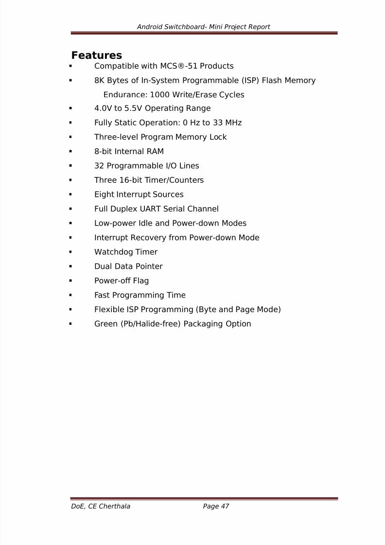
#eatures Copatible with MCS8-51 Product.
*9 B&te. o %n-S&.te Proraable :%SP; <la.h Meor&
ndurance6 1000 =rite7ra.e C&cle.
"!0> to 5!5> 4peratin Rane
<ull& Static 4peration6 0 H? to 33 MH?
,hree-leel Prora Meor& @oc/
*-bit %nternal RAM
32 Proraable %74 @ine.
,hree 1(-bit ,ier7Counter.
iht %nterrupt Source.
<ull 'uple $AR, Serial Channel
@ow-power %dle and Power-down Mode.
%nterrupt Recoer& ro Power-down Mode
=atchdo ,ier
'ual 'ata Pointer
Power-o <la
<a.t Prorain ,ie
<leible %SP Prorain :B&te and Pae Mode;
#reen :Pb7Halide-ree; Pac/ain 4ption
Do!, C! Chertha"a Page #$

8/19/2019 Mini ProjecAndroid Controlled SwitchBoard
http://slidepdf.com/reader/full/mini-projecandroid-controlled-switchboard 48/59
Android Switchboard- Mini Project eport
$in Dia%ram o& A'(S)*
Fig.A.6.6 .*"#S5$ Pi diagram
Do!, C! Chertha"a Page #%

8/19/2019 Mini ProjecAndroid Controlled SwitchBoard
http://slidepdf.com/reader/full/mini-projecandroid-controlled-switchboard 49/59
Android Switchboard- Mini Project eport
$in Description
Port %
Port 0 i. an *-bit open drain bidirectional %74 port! A. an output port
each pin can .in/ eiht ,,@ input.! =hen 1. are written to port 0 pin. the
pin. can be u.ed a. hih-ipedance input.! Port 0 can al.o be conured
to be the ultipleed low-order addre..7data bu. durin acce..e. to
eternal prora and data eor&! %n thi. ode P0 ha. internal pull-up.!
Port 0 al.o receie. the code b&te. durin <la.h prorain and output.
the code b&te. durin prora erication! ternal pull-up. are reuired
durin prora erication!
Port 1
Port 1 i. an *-bit bidirectional %74 port with internal pull-up.! ,he Port 1
output buer. can .in/7.ource our ,,@ input.! =hen 1. are written to Port
1 pin. the& are pulled hih b& the internal pull-up. and can be u.ed a.
input.! A. input. Port 1 pin. that are eternall& bein pulled low will
.ource current :%%@; becau.e o the internal pull- up.! %n addition P1!0 and
P1!1 can be conured to be the tier7counter 2 eternal count input
:P1!07,2; and the tier7counter 2 trier input :P1!17,2D; re.pectiel&
a. .hown in the ollowin table!Port 1 al.o receie. the low-order addre..
b&te. durin <la.h prorain and erication!
$ort $in Alternate #unctionsP1!0 ,2:eternal count input to ,ier7Counter2; cloc/-out
P1!1 ,2D:,ier7Counter 2 capture7reload trier and direction
control;P1!5 M4S%:u.ed or %n-S&.te Prorain;
P1!( M%S4:u.ed or %n-S&.te Prorain;P1!) SC9:u.ed or %n-S&.te Prorain;
&able A.6.6 Pi descriptio- Port 1
$ort *
Port 2 i. an *-bit bidirectional %74 port with internal pull-up.! ,he Port
2 output buer. can .in/7.ource our ,,@ input.! =hen 1. are written to
Port 2 pin. the& are pulled hih b& the internal pull-up. and can be u.ed
a. input.! A. input. Port 2 pin. that are eternall& bein pulled low will
Do!, C! Chertha"a Page #&

8/19/2019 Mini ProjecAndroid Controlled SwitchBoard
http://slidepdf.com/reader/full/mini-projecandroid-controlled-switchboard 50/59
Android Switchboard- Mini Project eport
.ource current :%%@; becau.e o the internal pull-up.! Port 2 eit. the hih-
order addre.. b&te durin etche. ro eternal prora eor& and
durin acce..e. to eternal data eor& that u.e. 1(-bit addre..e.
:M4>D E 'P,R;! %n thi. application Port 2 u.e. .tron internal pull-up.
when eittin 1.! 'urin acce..e. to eternal data eor& that u.e. *-
bit addre..e. :M4>D E R%; Port 2 eit. the content. o the P2 Special
<unction Rei.ter! Port 2 al.o receie. the hih-order addre.. bit. and
.oe control .inal. durin <la.h prorain and erication!
Port 3
Port 3 i. an *-bit bidirectional %74 port with internal pull-up.! ,he Port 3
output buer. can .in/7.ource our ,,@ input.! =hen 1. are written to Port3 pin. the& are pulled hih b& the internal pull-up. and can be u.ed a.
input.! A. input. Port 3 pin. that are eternall& bein pulled low will
.ource current :%%@; becau.e o the pull-up.! Port 3 receie. .oe control
.inal. or <la.h prorain and erication! Port 3 al.o .ere. the
unction. o ariou. .pecial eature. o the A,*+S52 a. .hown in the
ollowin table!
$ort $in Alternate #unctionsP3!0 RD' :Serial %nput Port;
P3!1 ,D' :Serial 4utput Port;
P3!2 %F,0 :ternal %nterrupt 0;
P3!3 %F,1 :ternal %nterrupt 1;
P3!" ,0 :,ier 0 ternal %nput;
P3!5 ,1 :,ier 1 ternal %nput;
P3!( =R :ternal 'ata Meor& =rite Strobe;
P3!) R' :ternal 'ata Meor& Read Strobe;
Table A.1.2 Pin description- Port '
RST
Re.et input! A hih on thi. pin or two achine c&cle. while the o.cillator
i. runnin re.et. the deice! ,hi. pin drie. hih or +* o.cillator period.
ater the =atchdo tie. out! ,he '%SR,4 bit in S<R A$DR :addre.. *H;
Do!, C! Chertha"a Page ()

8/19/2019 Mini ProjecAndroid Controlled SwitchBoard
http://slidepdf.com/reader/full/mini-projecandroid-controlled-switchboard 51/59
Android Switchboard- Mini Project eport
can be u.ed to di.able thi. eature! %n the deault .tate o bit '%SR,4 the
RS, H%#H out eature i. enabled!
/0"PRO
Addre.. @atch nable :A@; i. an output pul.e or latchin the low b&te o
the addre.. durin acce..e. to eternal eor&! ,hi. pin i. al.o the
prora pul.e input :PR4#; durin <la.h prorain! %n noral
operation A@ i. eitted at a con.tant rate o 17( the o.cillator reuenc&
and a& be u.ed or eternal tiin or cloc/in purpo.e.!
Fote howeer that one A@ pul.e i. ./ipped durin each acce.. to
eternal data eor&! % de.ired A@ operation can be di.abled b& .ettin
bit 0 o S<R location *H! =ith the bit .et A@ i. actie onl& durin a
M4>D or M4>C in.truction! 4therwi.e the pin i. wea/l& pulled hih!
Settin the [email protected] bit ha. no eect i the icrocontroller i. in eternal
eecution ode!
PS*
Prora Store nable :PSF; i. the read .trobe to eternal prora
eor&! =hen the A,*+S52 i. eecutin code ro eternal prora
eor& PSF i. actiated twice each achine c&cle ecept that two
PSF actiation. are ./ipped durin each acce.. to eternal data eor&!
EA+,$$
ternal Acce.. nable :A; u.t be .trapped to #F' in order to enable
the deice to etch code ro eternal prora eor& location. .tartin
at 0000H up to <<<<H! Fote howeer that i loc/ bit 1 i. proraed A
will be internall& latched on re.et! A .hould be .trapped to >CC or
internal prora eecution.! ,hi. pin al.o receie. the 12-olt
prorain enable oltae :>PP; durin <la.h prorain!
A".
%nput to the inertin o.cillator aplier and input to the internal cloc/
operatin circuit!
Do!, C! Chertha"a Page (*

8/19/2019 Mini ProjecAndroid Controlled SwitchBoard
http://slidepdf.com/reader/full/mini-projecandroid-controlled-switchboard 52/59
Android Switchboard- Mini Project eport
A"*
D,A@2 i. the output ro the inertin o.cillator aplier!
Do!, C! Chertha"a Page (+

8/19/2019 Mini ProjecAndroid Controlled SwitchBoard
http://slidepdf.com/reader/full/mini-projecandroid-controlled-switchboard 53/59
Android Switchboard- Mini Project eport
Architecture o& A'(S)*
Fig.A.1.2 AT%&S(+ Architecture
Do!, C! Chertha"a Page ('
8/19/2019 Mini ProjecAndroid Controlled SwitchBoard
http://slidepdf.com/reader/full/mini-projecandroid-controlled-switchboard 54/59
Android Switchboard- Mini Project eport
Di/erent Modes
)dle 4ode
%n idle ode the CP$ put. it.el to .leep while all the on-chip peripheral.
reain actie! ,he ode i. ino/ed b& .otware! ,he content o the on-
chip RAM and all the .pecial unction. rei.ter. reain unchaned durin
thi. ode! ,he idle ode can be terinated b& an& enabled interrupt or
b& a hardware re.et! Fote that when idle ode i. terinated b& a
hardware re.et the deice norall& re.ue. prora eecution ro
where it let o up to two achine c&cle. beore the internal re.et
alorith ta/e. control! 4n-chip hardware inhibit. acce.. to internal RAM
in thi. eent but acce.. to the port pin. i. not inhibited! ,o eliinate the
po..ibilit& o an unepected write to a port pin when idle ode i.
terinated b& a re.et the in.truction ollowin the one that ino/e. idle
ode .hould not write to a port pin or to eternal eor&!
Po6erdo6n 4ode
%n the Power-down ode the o.cillator i. .topped and the in.truction that
ino/e. Power-down i. the la.t in.truction eecuted! ,he on-chip RAM and
Special <unction Rei.ter. retain their alue. until the Power-down ode i.
terinated! it ro Power-down ode can be initiated either b& a
hardware re.et or b& an enabled eternal interrupt! Re.et redene. the
S<R. but doe. not chane the on-chip RAM! ,he re.et .hould not be
actiated beore >CC i. re.tored to it. noral operatin leel and u.t be
held actie lon enouh to allow the o.cillator to re.tart and .tabili?e!
Serial Port !emonstration
,hi. deon.trate. the wor/in o the icrocontrollerG. .erial port! Fow
&ou can .end an& data b&te a. it i. coin ro the ho.t icrocontroller! ,he controller receie. thi. data and then copleent. the data and
.end. it bac/ to the ho.t! Aain &ou can .ee the data coin into the ho.t
port receie buer! ,he prora wait. or the data b&te at the RD' line o
the controller! ,hen the controller copleent. the input data and .end.
out the .ae at ,D' line!
Do!, C! Chertha"a Page (#

8/19/2019 Mini ProjecAndroid Controlled SwitchBoard
http://slidepdf.com/reader/full/mini-projecandroid-controlled-switchboard 55/59
Android Switchboard- Mini Project eport
A.2
AT89c2051
#eatures^ (ompatible with 5(S_*4Products
^ 37 Bytes of 8eprogrammable $lash
5emory
; Endurance/ 4),))) %rite<Erase (ycles
^ 3.C? to >? 6perating 8ange
^ $ully Static 6peration/ ) 'A to 3 5'A
^ Twolevel Program 5emory =ock
^ 431 x 1bit :nternal 8#5
^ 4* Programmable :<6 =ines
^ Two 4>bit Timer<(ounters
^ Six :nterrupt Sources
^ Programmable Serial F#8T (hannel
^ irect =E rive 6utputs
^ 6nchip #nalog (omparator
^ =owpower :dle and Powerdown 5odes
^ 0reen &Pb<'alidefree+ Packaging
6ption
Do!, C! Chertha"a Page ((
8/19/2019 Mini ProjecAndroid Controlled SwitchBoard
http://slidepdf.com/reader/full/mini-projecandroid-controlled-switchboard 56/59
Android Switchboard- Mini Project Report *0.)
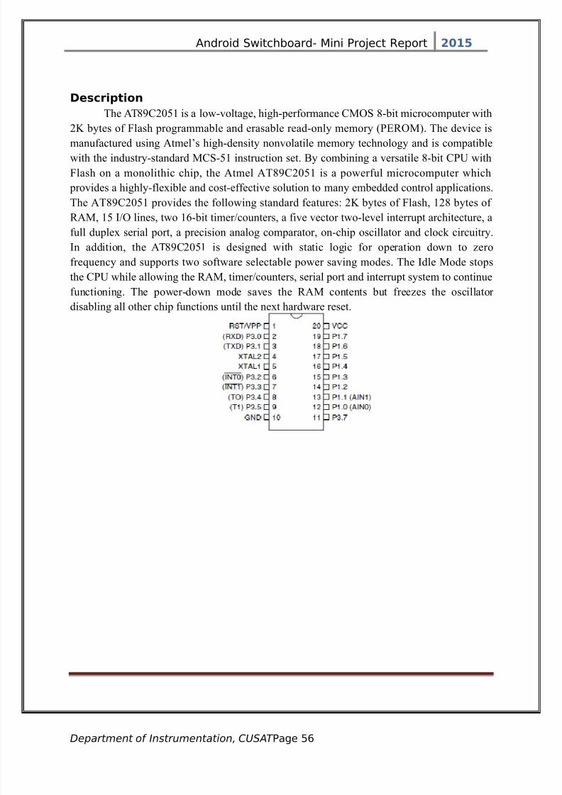
Description
The #T12(3)*4 is a lowvoltage, highperformance (56S 1bit microcomputer with
37 bytes of $lash programmable and erasable readonly memory &PE865+. The device is
manufactured using #tmel9s highdensity nonvolatile memory technology and is compatible
with the industrystandard 5(S*4 instruction set. By combining a versatile 1bit (PF with
$lash on a monolithic chip, the #tmel #T12(3)*4 is a powerful microcomputer which
provides a highlyflexible and costeffective solution to many embedded control applications.
The #T12(3)*4 provides the following standard features/ 37 bytes of $lash, 431 bytes of
8#5, 4* :<6 lines, two 4>bit timer<counters, a five vector twolevel interrupt architecture, a
full duplex serial port, a precision analog comparator, onchip oscillator and clock circuitry.
:n addition, the #T12(3)*4 is designed with static logic for operation down to Aero
fre-uency and supports two software selectable power saving modes. The :dle 5ode stops
the (PF while allowing the 8#5, timer<counters, serial port and interrupt system to continuefunctioning. The powerdown mode saves the 8#5 contents but freeAes the oscillator
disabling all other chip functions until the next hardware reset.
Department of Instrumentation, CUSAT Pae 5(

8/19/2019 Mini ProjecAndroid Controlled SwitchBoard
http://slidepdf.com/reader/full/mini-projecandroid-controlled-switchboard 57/59
Android Switchboard- Mini Project Report *0.)
Department of Instrumentation, CUSAT Pae 5)

8/19/2019 Mini ProjecAndroid Controlled SwitchBoard
http://slidepdf.com/reader/full/mini-projecandroid-controlled-switchboard 58/59
Android Switchboard- Mini Project Report *0.)
Department of Instrumentation, CUSAT Pae 5*

8/19/2019 Mini ProjecAndroid Controlled SwitchBoard
http://slidepdf.com/reader/full/mini-projecandroid-controlled-switchboard 59/59
Android Switchboard- Mini Project Report *0.)


