
GSM Association Non-confidential
Official Document TS.40 - MIoT Field and Lab Test Cases
V2.0 Page 1 of 72
MIoT Field and Lab Test Cases
Version 2.0
22 December 2017
This is a Non-binding Permanent Reference Document of the GSMA
Security Classification: Non-confidential
Access to and distribution of this document is restricted to the persons permitted by the security classification. This document is confidential to the
Association and is subject to copyright protection. This document is to be used only for the purposes for which it has been supplied and
information contained in it must not be disclosed or in any other way made available, in whole or in part, to persons other than those permitted
under the security classification without the prior written approval of the Association.
Copyright Notice
Copyright © 2018 GSM Association
Disclaimer
The GSM Association (“Association”) makes no representation, warranty or undertaking (express or implied) with respect to and does not accept
any responsibility for, and hereby disclaims liability for the accuracy or completeness or timeliness of the information contained in this document.
The information contained in this document may be subject to change without prior notice.
Antitrust Notice
The information contain herein is in full compliance with the GSM Association’s antitrust compliance policy.

GSM Association Non-confidential
Official Document TS.40 - MIoT Field and Lab Test Cases
V2.0 Page 2 of 72
Table of Contents
1 Introduction 4
1.1 Overview 4
1.2 Scope 4
1.1 Classification of Individual Test Scenarios 5
1.2 Definitions 5
1.3 Abbreviations 8
1.4 References 10
2 Basic Operation 11
2.1 Registration (Attach/Detach) 11
2.1.1 CAT-M1 Device Attach Procedure with Control Plane CIoT EPS
Optimization 11
2.1.2 CAT-M1 Device Attach Procedure with User Plane CIoT EPS
Optimization 13
2.1.3 CAT-M1 Device Attach Procedure with CIoT EPS Optimization (EMM
Registered without PDN Connection) 15
2.1.4 CAT-NB1 Device Attach Procedure with Control Plane CIoT EPS
Optimization – without PDN 17
2.1.5 CAT-NB1 Device Attach Procedure with Control Plane CIoT EPS
Optimization – with PDN 19
2.1.6 CAT-NB1 Device Attach Procedure with User Plane CIoT EPS
Optimization – without PDN 21
2.1.7 CAT-NB1 Device Attach Procedure with User Plane CIoT EPS
Optimization – with PDN 22
2.1.8 CAT-NB1 Device Attach Procedure with CIoT EPS Optimizations (SMS
transfer without Combined Attach) 24
2.1.9 Attach Procedure / Reject / No suitable cell in TA (EMM cause #15) 26
2.1.10 Device Detach Procedure Description 27
2.2 Paging 27
2.2.1 Paging Procedure 27
2.3 Data Transfer 28
2.3.1 Data Transfer use IP/non-IP/SMS with CP/UP 28
2.3.2 Suspend Resume 31
2.3.3 Serving PLMN Rate Control / APN Rate Control 34
2.4 Mobility Performance 36
2.4.1 IDLE-Mode Mobility 36
2.4.2 Connected Mode Mobility 39
2.5 Device Capabilities 41
2.5.1 CAT-NB1 Uplink Transmission Capability – 3.7kHz (Single-tone) 41
2.5.2 CAT-NB1 Uplink Transmission Capability - 15kHz (Single-tone) 42
2.5.3 CAT-NB1 Uplink Transmission Capability - 15kHz (Multi-tone) 42
3 Device Performance in Enhanced Coverage 43
3.1 Registration 43
3.1.1 Attach Performance with Control Plane CIoT EPS Optimizations 43

GSM Association Non-confidential
Official Document TS.40 - MIoT Field and Lab Test Cases
V2.0 Page 3 of 72
3.1.2 Attach Performance with User Plane CIoT EPS Optimizations 44
3.2 Paging 45
3.2.1 Paging performance under different coverage level 45
3.2.2 Paging with eDRX cycle under different coverage level 45
3.3 Data Transfer and Throughput 46
3.3.1 Data Transfer and Throughput with Control Plane CIoT EPS
Optimizations - IP PDN Type 46
3.3.2 Data Transfer and Throughput with Control Plane CIoT EPS
Optimizations - Non IP PDN Type 47
3.3.3 Data Transfer and Throughput with User Plane CIoT EPS Optimizations
- IP PDN Type 48
3.3.4 Data Transfer and Throughput with User Plane CIoT EPS Optimizations
- Non IP PDN Type 49
3.4 Mobility Performance 49
3.4.1 Idle Mode Mobility Performance – Cell Reselection 49
3.4.2 Connected Mode Mobility Performance 50
4 Power Optimized Operation 51
4.1 PSM Operation 51
4.1.1 PSM Request, Activation and Modification 51
4.1.2 MT Data in PSM State 52
4.1.3 MO Data in PSM State 52
4.1.4 Periodic Tracking Area Update 53
4.1.5 Periodic Tracking Area Update, T3412 54
4.1.6 Reduced Current Drain in PSM 55
4.1.7 Periodic Tracking Area Update Power Consumption Performance 56
4.2 I-eDRX Operation 57
4.2.1 eDRX Request, Activation and Modification 57
4.2.2 Power Consumption in Idle State with eDRX 58
4.3 Data transmission power consumption 59
4.3.1 CAT-M1 Device Uplink Transmission Power Consumption 59
4.3.2 CAT-NB1 Device Uplink Transmission Power Consumption 60
4.3.3 Downlink Transmission Power Consumption 61
5 Service Layer 62
5.1 oneM2M 62
5.2 LwM2M 62
6 USIM/eUICC OTA 63
7 USIM Toolkit 63
8 Antenna Performance 63
9 Device Management (LwM2M) 63
10 Mapping of Test Cases to Requirements 64
Annex A Individual Test Scenario Classification and Proforma 71
Annex B Document Management 72
B.1 Document History 72
B.2 Other Information 72
GSM Association Non-confidential
Official Document TS.40 - MIoT Field and Lab Test Cases
V2.0 Page 4 of 72
1 Introduction
1.1 Overview
This document contains a set of guidelines for the tests that should be performed in the
course of Field Test and Lab Test carried out on LPWA (Low Power Wide Area) Mobile IoT
modules and devices.
Field Tests are tests undertaken during later phases of the terminal development against a
real live deployed network (i.e. in the field) to prove of a feature or technology.
Lab Tests are tests undertaken during later phases of the terminal development against
laboratory based network components, representative of a real deployed network, to prove a
feature or technology.
Field Tests are required to ensure confidence in the performance of Mobile IoT modules and
devices in the operational network environment. Lab Tests usually complement Field Tests
for scenarios which cannot be easily executed in a live network.
It is assumed that Field Tests shall be performed without direct support from the network
operator. However TSG and its operator delegates do offer their assistance, if required by
any Manufacturer in terms of drafting Field and/or Lab Tests, providing network specific
information, etc.
The Field and/or Lab Tests in this document may be performed in any order that is
convenient. Only the features supported by the DUT shall be tested.
It is recommended to use a logging tool, if available, to take log files when running the tests.
The log files and their indication of network conditions/behaviour during the tests will help to
remove any ambiguity that may come out of the test results.
Also more specifically about the performances tests, it is recommended to run the tests with
the terminal to be certified and with a reference terminal such as, a competitive terminal
available on the market. The behaviour of the reference platform will help to remove any
ambiguity about the test results.
In order to provide visibility on the applicability, extent and the result of Field and/or Lab
Tests conducted on Mobile IoT modules and devices, Annex A has been included in this
document.
1.2 Scope
This document defines all test cases for PTCRB and GCF Certification of LPWA MIoT
modules and devices that are to be deployed in mobile networks that support LPWA
modules and devices.
These test cases shall be executed against the requirements document as identified within
the MIoT Requirements document TS.39 V2.0 which reflects the specifications as identified
in the 3GPP Rel 13 Specifications published in June 2016.

GSM Association Non-confidential
Official Document TS.40 - MIoT Field and Lab Test Cases
V2.0 Page 5 of 72
This document does not replicate any test cases that are currently defined within the GSMA
Device Connection Efficiency Test Book TS.35 [9]. Any test cases in this respect will be
agreed between the respective MNO’s and their Vendors and is outside the scope of this
document.
It should be noted that the test cases listed within this document are those that are deemed
as a priority by the MNOs for accreditation of MIoT devices onto their networks.
1.1 Classification of Individual Test Scenarios
Every individual test scenario is classified in Field Test, Lab Test or both. This classification
should adhere to the following criteria:
Field Test only:
Confidence is only given that this feature works correctly when it has been tested in
the field on real live commercial networks.
It is possible to execute this test in the field (assuming there are live commercial
network deployments).
The only exception to this rule is when a vendor wishes to test a feature for which
there are no commercial network deployments. In this case the feature MAY be lab
tested for the purpose of gaining some basic confidence in the feature. If this option is
used by the vendor then only a ‘provisional pass’ of the test can be achieved and this
must clearly be marked in the vendors test report.
Lab Test only:
Technically, it is only practical for this test to be executed in a lab.
Executing this test in the lab MAY not give the same level of confidence that the
feature will work correctly on real live networks, however it may provide some basic
confidence in the feature.
For the identification of absolute performance of the handset, it is better to perform
this test in a controlled (Lab-) environment, where resources are allocated only for the
handset.
Both, Field Test and Lab Test:
If there are severe practical difficulties in executing this test in the field then this test
MAY be executed in a lab.
There is equal confidence in the proper function of this feature regardless of whether
it is tested in the Field or Lab environment. Passing the test in the lab is therefore
equally valid as passing the test in the field.
The individual classification of a test scenario is listed in Annex A.
1.2 Definitions
The key words "SHALL", "SHOULD" and "MAY", within this document are to be interpreted
as described in RFC 2119 [19], an abstract of which is included within the table below.

GSM Association Non-confidential
Official Document TS.40 - MIoT Field and Lab Test Cases
V2.0 Page 6 of 72
Term Description
MUST This word, or the terms "REQUIRED" or "SHALL", mean that the definition is an absolute requirement of the specification.
SHOULD This word, or the adjective "RECOMMENDED", mean that there may exist valid reasons in particular circumstances to ignore a particular item, but the full implications must be understood and carefully weighed before choosing a different course.
MAY This word, or the adjective "OPTIONAL", mean that an item is truly optional.
One vendor may choose to include the item because a particular marketplace
requires it or because the vendor feels that it enhances the product while
another vendor may omit the same item. An implementation which does not
include a particular option MUST be prepared to interoperate with another
implementation which does include the option, though perhaps with reduced
functionality. In the same vein an implementation which does include a
particular option MUST be prepared to be interoperate with another
implementation which does not include the option (except, of course, for the
feature the option provides.)
Actor
Physical entity (person, company or organisation) that can assume a Role in
the functional architecture. It is possible for an Actor to assume multiple Roles
in the same functional architecture.
Client
Any device that is used to help fulfil the field trial requirement. A Client may be a cellular device, software client, a server, a system simulator or other device used to complete a test, if not defined otherwise in Initial Configuration These additional devices are by default identified as Client-1, Client-2, Client-3, … etc.
Connectivity
Parameters
A set of data (for example SMSC address) required by the eUICC to open a
communication channel (for example SMS, HTTPS) on a dedicated network.
Customer A paying party, in particular a legally responsible juridical person or entity.
Device Equipment into which an Embedded UICC and a communication module are
inserted during assembly. Examples include Utility meter, car and camera.
Disabled (Profile) The state of a Profile where all files and applications (for example NAA)
present in the Profile are not selectable over the eUICC-Terminal interface.
Embedded UICC
(eUICC)
A UICC which is not easily accessible or replaceable, is not intended to be
removed or replaced in the Device, and enables the secure changing of
Profiles.
Enabled (Profile) The state of a Profile when its files and/or applications (for example, NAA) are
selectable over the UICC-Terminal interface.
eUICC
Manufacturer
Supplier of the eUICCs and resident software (for example firmware and
operating system).
International
Mobile Subscriber
Identity
Unique identifier owned and issued by Mobile operators to (U) SIM
applications to enable Devices to attach to a network and use services.

GSM Association Non-confidential
Official Document TS.40 - MIoT Field and Lab Test Cases
V2.0 Page 7 of 72
Term Description
MIoT Device
A Mobile IoT (MIoT) Device is a generic term to indicate one of the following
3GPP standard technologies for LPWA: CAT-M1, CAT-NB1 and EC-GSM-
IoT.
Mobile Network
Operator
An entity providing access capability and communication services to its
Customers through a mobile network infrastructure.
3GPP module
A communications module complying with one or more of the 3GPP
communication technologies such as 2G, 3G, EC-GSM-IoT, CAT-NB1 or
CAT-M1, this includes all necessary eUICC or UICC components. Can also
be called User Equipment or UE.
Network Access
Application
An application residing on a UICC which provides authorisation to access a
network for example a USIM application.
Profile
Combination of a file structure, data and applications to be provisioned onto,
or present on, an eUICC and which allows, when enabled, the access to a
specific mobile network infrastructure.
Profile Component
A Profile Component is an element of the Profile and may be one of the
following:
An element of the file system like an MF, EF or DF
An Application, including NAA and Security Domain
POL1
MNO-SD.
Reference Device
A specific device with similar capabilities as the DUT that has already been
successfully field trialed for the test being performed, if not defined otherwise
in Initial Configuration.
This is used when a performance or behavior comparison is required to
confirm the pass criteria of the DUT.
These additional devices are by default identified as Reference-1, Reference-
2, Reference-3, etc.
See also Client.
Roles Roles are representing a logical grouping of functions.
SIM
Subscriber Identity Module; a physical entity that contains keys and ID
required to authenticate a user on a mobile network. “SIM” is commonly used
to refer to the physical entity that is technically called the UICC (see UICC
definition below).This document generally uses “SIM” to refer to the physical
entity

GSM Association Non-confidential
Official Document TS.40 - MIoT Field and Lab Test Cases
V2.0 Page 8 of 72
Term Description
Subscriber
An entity (associated with one or more users) that is engaged in a
Subscription with a Telecommunication Service Provider. The Subscriber is
allowed to subscribe and unsubscribe to services, to register a user or a list of
users authorised to use those services, and also to set the limits relative to
the use that associated users make of those services.
Subscription Describes the commercial relationship between the Subscriber and the
Telecommunication Service Provider.
Subscription
Manager Data
Preparation
Role that prepares the Profiles and manages the secure download and
installation of these Profiles onto the eUICC.
Subscription
Manager Secure
Routing
Role that securely performs functions of Platform Management commands
and the transport of Profile Management commands.
Telecommunication
Service Provider
The organization through which the Subscriber obtains PLMN
telecommunication services. This is usually the network operator or possibly a
separate body.
Test Route
A route preferably provided by the operator and contains ideally all mobility scenarios supported by the operator’s network. In case no Test Route is or can be provided by the operator a test route will follow the limited set below. In both cases the test route should not exceed 50 km in length or can be completed in approximately 30 min. during off-peak hours and normal road traffic conditions.
UICC Universal Integrated Circuit Card; the physical entity that contains as a
minimum the SIM/USIM application
USIM An application that runs on the UICC and provides authentication functions
similar to those provided by the SIM in pre-3G systems
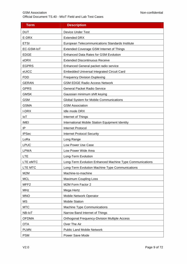
1.3 Abbreviations
Term Description
3GPP 3rd Generation Partnership Project
BGA Ball Grid Array
CAT-NB1 Category Narrow Band 1
CAT-M1 Category M1
C-DRX Connected mode DRX
CIoT Cellular Internet of Things
dB Decibel
dBm Decibel-referenced to 1 milliwatt
DFN Dual Flat No lead package
DRX Discontinuous Reception
DL Downlink
GSM Association Non-confidential
Official Document TS.40 - MIoT Field and Lab Test Cases
V2.0 Page 9 of 72
Term Description
DUT Device Under Test
E-DRX Extended DRX
ETSI European Telecommunications Standards Institute
EC-GSM-IoT Extended Coverage GSM Internet of Things
EDGE Enhanced Data Rates for GSM Evolution
eDRX Extended Discontinuous Receive
EGPRS Enhanced General packet radio service
eUICC Embedded Universal Integrated Circuit Card
FDD Frequency Division Duplexing
GERAN GSM EDGE Radio Access Network
GPRS General Packet Radio Service
GMSK Gaussian minimum shift keying
GSM Global System for Mobile Communications
GSMA GSM Association
I-DRX Idle mode DRX
IoT Internet of Things
IMEI International Mobile Station Equipment Identity
IP Internet Protocol
IPSec Internet Protocol Security
LoRa Long Range
LPUC Low Power Use Case
LPWA Low Power Wide Area
LTE Long-Term Evolution
LTE eMTC Long-Term Evolution Enhanced Machine Type Communications
LTE MTC Long-Term Evolution Machine Type Communications
M2M Machine-to-machine
MCL Maximum Coupling Loss
MFF2 M2M Form Factor 2
MHz Mega Hertz
MNO Mobile Network Operator
MS Mobile Station
MTC Machine Type Communications
NB-IoT Narrow Band Internet of Things
OFDMA Orthogonal Frequency-Division Multiple Access
OTA Over The Air
PLMN Public Land Mobile Network
PSM Power Save Mode

GSM Association Non-confidential
Official Document TS.40 - MIoT Field and Lab Test Cases
V2.0 Page 10 of 72
Term Description
QoS Quality of Service
RAN Radio Access Network
RF Radio Frequency
SC-FDMA Single-carrier frequency-division multiple access
SIM Subscriber Identity Module (an application running on a UICC)
SMS Short Message Service
TA Tracking Area
TAU Tracking Area Update
TCO Total Cost of Ownership
TDMA Time division multiple access
TR Technical Report
UE User Equipment
UICC Universal Integrated Circuit Card (sometimes known as the SIM card)
UL Uplink
USIM Universal Subscriber Identity Module
UTDOA Uplink-Time Difference of Arrival
WAN Wide Area Network
Wi-Fi Wireless Fidelity
WLCSP Wafer-level redistribution Chip Scale Package
1.4 References
Ref Doc Number Title
[1] 3GPP TS 31.120 UICC-Terminal Interface; Physical, electrical and logical
test specification, Release 13 or higher.
[2] 3GPP TS 31.121
“UICC-Terminal interface; Universal Subscriber Identity
Module (USIM) application test specification, Release 13
or higher.
[3] 3GPP TS 31.124
Mobile Equipment (ME) conformance test specification;
Universal Subscriber Identity Module Application Toolkit
(USAT) conformance test specification, Release 13 or
higher.
[4]
OMA-ETS-
LightweightM2M-
V1_0_1
Enabler Test Specification for Lightweight M2M v1.0,
publication date 20170830 or later.
[5] oneM2M TS
0013 oneM2M Interoperability Testing
[6] oneM2M TS
0017 oneM2M Implementation Conformance Statements
[7] oneM2M TS
0018 oneM2M Test Suite Structure and Test Purposes

GSM Association Non-confidential
Official Document TS.40 - MIoT Field and Lab Test Cases
V2.0 Page 11 of 72
Ref Doc Number Title
[8] oneM2M TS
0019
oneM2M Abstract Test Suite & Implementation eXtra
Information for Test
[9] GSMA TS.35 IoT Device Connection Efficiency Test Book, Version 3.0,
30 March 2016
[10] 3GPP TS.34.114 User Equipment (UE) / Mobile Station (MS) Over The Air (OTA)
antenna performance; Conformance testing
[11] 3GPP TS.37.544
Universal Terrestrial Radio Access (UTRA) and Evolved
UTRA (E-UTRA); User Equipment (UE) Over The Air
(OTA) performance; Conformance testing
[12] CTIA OTA Test
Plan v3.6 Test Plan for Wireless Device Over-the-Air Performance
[13] RFC2119 Key words for use in RFCs to Indicate Requirement Levels
[14] 3GPP TS.36.304 Evolved Universal Terrestrial Radio Access (E-UTRA);
User Equipment (UE) procedures in idle mode
[15] 3GPP TS36.321 Evolved Universal Terrestrial Radio Access (E-UTRA);
Medium Access Control (MAC) protocol specification
[16] 3GPP TS.36.331 Evolved Universal Terrestrial Radio Access (E-UTRA);
Radio Resource Control (RRC); Protocol specification
2 Basic Operation
2.1 Registration (Attach/Detach)
2.1.1 CAT-M1 Device Attach Procedure with Control Plane CIoT EPS
Optimization
Description
CAT-M1 device could successfully perform LTE Attach Procedure with Control Plane CIoT EPS Optimizations.
Related core specifications
GSMA TS.39_2.2.2_REQ_001 (Attach)
GSMA TS.39_2.3.2_REQ_001 (Device Capabilities)
3GPP TS 23.401, 24.301 and 36.331
Reason for test
To verify that CAT-M1 device could successfully perform LTE Attach Procedure with Control Plane CIoT EPS Optimizations.
Initial configuration
DUT is configured with “Control Plane CIoT EPS Optimizations” in “Preferred and Supported Network Behaviour”
DUT is Switched OFF
The NW is configured to support CAT-M1 and “Control Plane CIoT EPS Optimizations”
Test procedure

GSM Association Non-confidential
Official Document TS.40 - MIoT Field and Lab Test Cases
V2.0 Page 12 of 72
Step Test procedure Expected behaviour
1 Switch on DUT DUT is in EMM-IDLE mode reads SIB2; set
up RRC connection and sends Attach
Request message indicating support of
“Control Plane CIoT EPS Optimization”
together with PDN CONNECTIVITY
REQUEST Message.
2
Verify the DUT sends Attach
AcceptComplete after reception of Attach
Accept message from NW
Upon reception of Attach Accept message
from NW DUT successfully completes
attach procedure by sending Attach
Complete Message
Example message flow:
Step Direction
UE - NW Message Comments
1a --> RRC: RRCConnection Request
After DUT has read SIB-2 to
verify that “Control Plane
CIoT EPS Optimizations” is
broadcast in EUTRAN Cell
it sends RRC Connection
Request
1b <-- RRC: RRCConnectionSetup
1c -->
RRC: RRCConnectionSetupComplete
NAS: ATTACH REQUEST
NAS: PDN CONNECTIVITY REQUEST
Attach Request message
indicates support of “Control
Plane CIoT EPS
Optimization”
1d <-- RRC: DLInformationTransfer
NAS: AUTHENTICATION REQUEST
1e --> RRC: ULInformationTransfer
NAS: AUTHENTICATION RESPONSE
1f <-- RRC: DLInformationTransfer
NAS: SECURITY MODE COMMAND
1g --> RRC: ULInformationTransfer
NAS: SECURITY MODE COMPLETE
1h <-- RRC: DLInformationTransfer
NAS: ESM INFORMATION REQUEST
1i --> RRC: ULInformationTransfer
NAS: ESM INFORMATION RESPONSE
1j <-- RRC: SecurityModeCommand
1k --> RRC: SecurityModeComplete
1l <-- RRC: UECapabilityEnquiry
GSM Association Non-confidential
Official Document TS.40 - MIoT Field and Lab Test Cases
V2.0 Page 13 of 72
Step Direction
UE - NW Message Comments
1m -->
RRC: UECapabilityInformation RRC UE Capability
Information Message will
include E-UTRAN
parameter, Inter-RAT
parameter and Radio
Paging Information
2a <--
RRC: RRCConnectionReconfiguration
NAS: ATTACH ACCEPT
NAS: ACTIVATE DEFAULT EPS BEARER
CONTEXT REQUEST
2b --> RRC: RRCConnectionReconfigurationComplete
2c -->
RRC: ULInformationTransfer
NAS: ATTACH COMPLETE
NAS: ACTIVATE DEFAULT EPS BEARER
CONTEXT ACCEPT
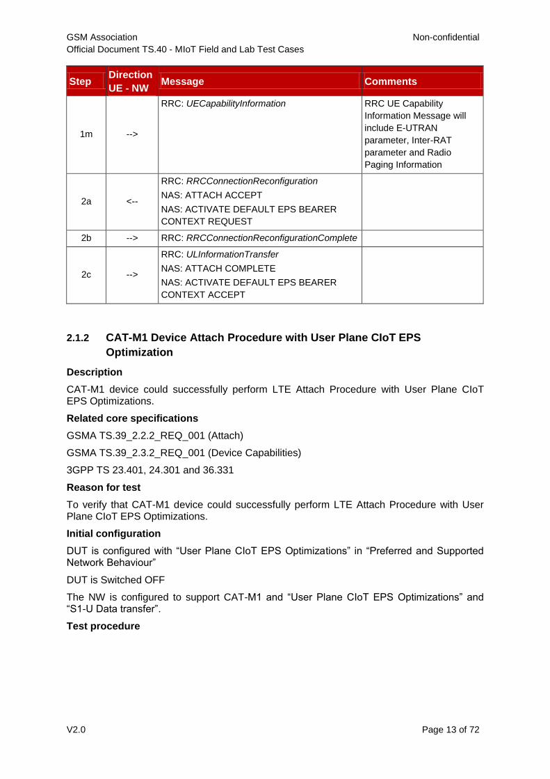
2.1.2 CAT-M1 Device Attach Procedure with User Plane CIoT EPS
Optimization
Description
CAT-M1 device could successfully perform LTE Attach Procedure with User Plane CIoT EPS Optimizations.
Related core specifications
GSMA TS.39_2.2.2_REQ_001 (Attach)
GSMA TS.39_2.3.2_REQ_001 (Device Capabilities)
3GPP TS 23.401, 24.301 and 36.331
Reason for test
To verify that CAT-M1 device could successfully perform LTE Attach Procedure with User Plane CIoT EPS Optimizations.
Initial configuration
DUT is configured with “User Plane CIoT EPS Optimizations” in “Preferred and Supported Network Behaviour”
DUT is Switched OFF
The NW is configured to support CAT-M1 and “User Plane CIoT EPS Optimizations” and “S1-U Data transfer”.
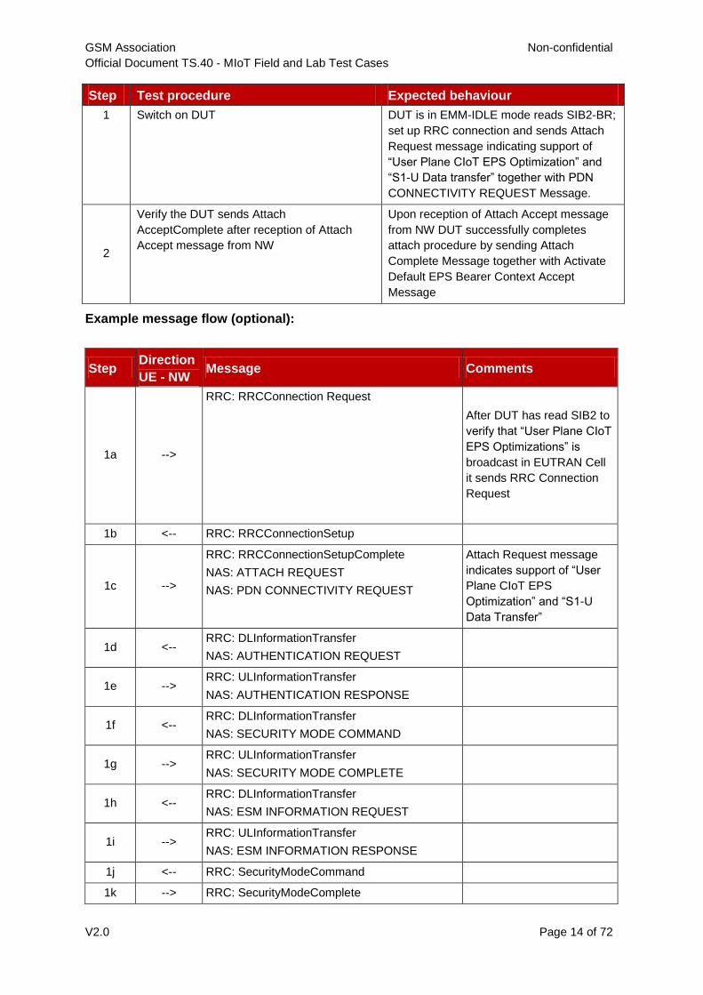
Test procedure
GSM Association Non-confidential
Official Document TS.40 - MIoT Field and Lab Test Cases
V2.0 Page 14 of 72
Step Test procedure Expected behaviour
1 Switch on DUT DUT is in EMM-IDLE mode reads SIB2-BR;
set up RRC connection and sends Attach
Request message indicating support of
“User Plane CIoT EPS Optimization” and
“S1-U Data transfer” together with PDN
CONNECTIVITY REQUEST Message.
2
Verify the DUT sends Attach
AcceptComplete after reception of Attach
Accept message from NW
Upon reception of Attach Accept message
from NW DUT successfully completes
attach procedure by sending Attach
Complete Message together with Activate
Default EPS Bearer Context Accept
Message
Example message flow (optional):
Step Direction
UE - NW Message Comments
1a -->
RRC: RRCConnection Request
After DUT has read SIB2 to
verify that “User Plane CIoT
EPS Optimizations” is
broadcast in EUTRAN Cell
it sends RRC Connection
Request
1b <-- RRC: RRCConnectionSetup
1c -->
RRC: RRCConnectionSetupComplete
NAS: ATTACH REQUEST
NAS: PDN CONNECTIVITY REQUEST
Attach Request message
indicates support of “User
Plane CIoT EPS
Optimization” and “S1-U
Data Transfer”
1d <-- RRC: DLInformationTransfer
NAS: AUTHENTICATION REQUEST
1e --> RRC: ULInformationTransfer
NAS: AUTHENTICATION RESPONSE
1f <-- RRC: DLInformationTransfer
NAS: SECURITY MODE COMMAND
1g --> RRC: ULInformationTransfer
NAS: SECURITY MODE COMPLETE
1h <-- RRC: DLInformationTransfer
NAS: ESM INFORMATION REQUEST
1i --> RRC: ULInformationTransfer
NAS: ESM INFORMATION RESPONSE
1j <-- RRC: SecurityModeCommand
1k --> RRC: SecurityModeComplete

GSM Association Non-confidential
Official Document TS.40 - MIoT Field and Lab Test Cases
V2.0 Page 15 of 72
Step Direction
UE - NW Message Comments
1l <-- RRC: UECapabilityEnquiry
1m -->
RRC: UECapabilityInformation RRC UE Capability
Information Message will
include E-UTRAN
parameter, Inter-RAT
parameter and Radio
Paging Information
2a <--
RRC: RRCConnectionReconfiguration
NAS: ATTACH ACCEPT
NAS: ACTIVATE DEFAULT EPS BEARER
CONTEXT REQUEST
2b --> RRC: RRCConnectionReconfigurationComplete
2c -->
RRC: ULInformationTransfer
NAS: ATTACH COMPLETE
NAS: ACTIVATE DEFAULT EPS BEARER
CONTEXT ACCEPT
2.1.3 CAT-M1 Device Attach Procedure with CIoT EPS Optimization (EMM
Registered without PDN Connection)
Description
CAT-M1 device could successfully perform LTE Attach Procedure with CIoT EPS Optimizations without PDN connection.
Related core specifications
GSMA TS.39_2.2.2_REQ_001 (Attach)
GSMA TS.39_2.3.2_REQ_001 (Device Capabilities)
3GPP TS 23.401, 24.301 and 36.331
Reason for test
To verify that CAT-M1 device could successfully perform LTE Attach Procedure with CIoT EPS Optimizations without PDN connection.
Initial configuration
DUT is configured with “attachwithoutPDN Connectivity” in “Preferred and Supported Network Behaviour”
DUT is Switched OFF
The NW is configured to support CAT-M1 and “attachwithoutPDN Connectivity”
Test procedure
GSM Association Non-confidential
Official Document TS.40 - MIoT Field and Lab Test Cases
V2.0 Page 16 of 72
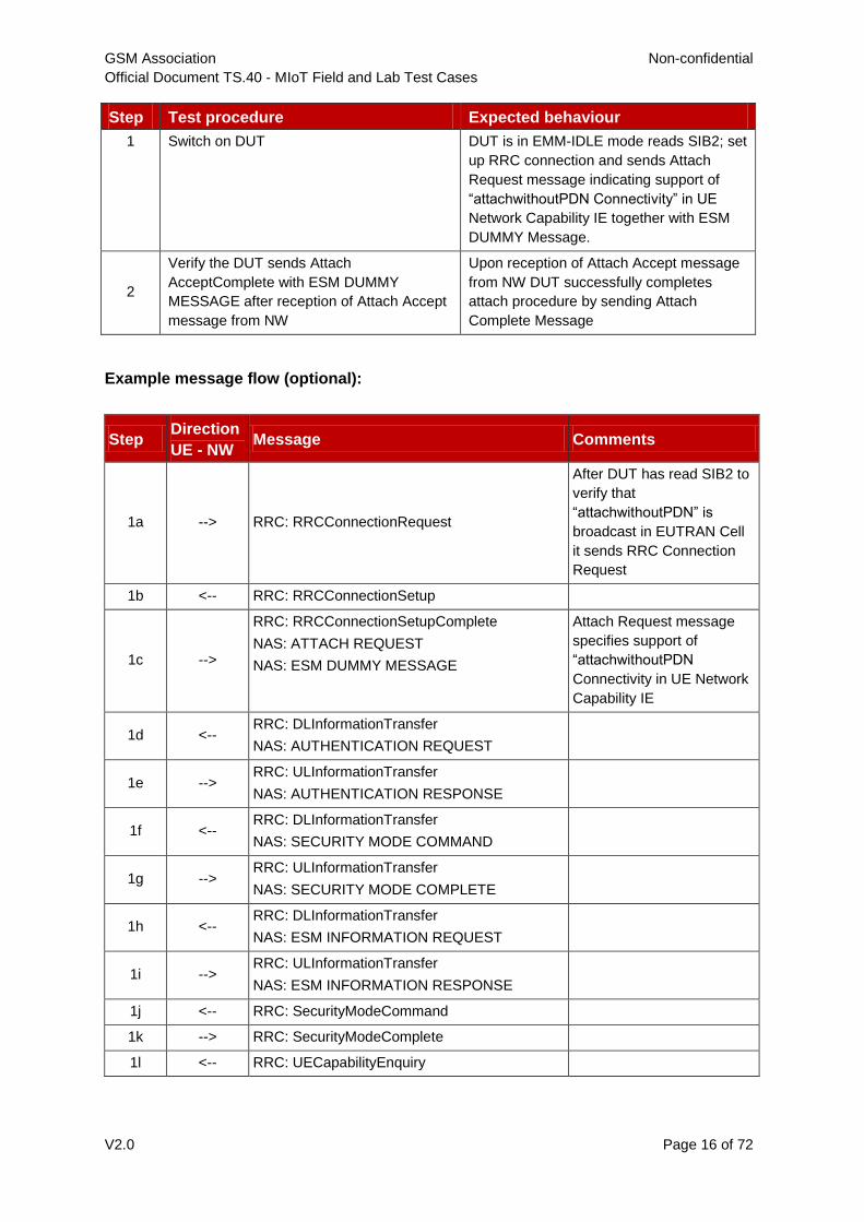
Step Test procedure Expected behaviour
1 Switch on DUT DUT is in EMM-IDLE mode reads SIB2; set
up RRC connection and sends Attach
Request message indicating support of
“attachwithoutPDN Connectivity” in UE
Network Capability IE together with ESM
DUMMY Message.
2
Verify the DUT sends Attach
AcceptComplete with ESM DUMMY
MESSAGE after reception of Attach Accept
message from NW
Upon reception of Attach Accept message
from NW DUT successfully completes
attach procedure by sending Attach
Complete Message
Example message flow (optional):
Step Direction
UE - NW Message Comments
1a --> RRC: RRCConnectionRequest
After DUT has read SIB2 to
verify that
“attachwithoutPDN” is
broadcast in EUTRAN Cell
it sends RRC Connection
Request
1b <-- RRC: RRCConnectionSetup
1c -->
RRC: RRCConnectionSetupComplete
NAS: ATTACH REQUEST
NAS: ESM DUMMY MESSAGE
Attach Request message
specifies support of
“attachwithoutPDN
Connectivity in UE Network
Capability IE
1d <-- RRC: DLInformationTransfer
NAS: AUTHENTICATION REQUEST
1e --> RRC: ULInformationTransfer
NAS: AUTHENTICATION RESPONSE
1f <-- RRC: DLInformationTransfer
NAS: SECURITY MODE COMMAND
1g --> RRC: ULInformationTransfer
NAS: SECURITY MODE COMPLETE
1h <-- RRC: DLInformationTransfer
NAS: ESM INFORMATION REQUEST
1i --> RRC: ULInformationTransfer
NAS: ESM INFORMATION RESPONSE
1j <-- RRC: SecurityModeCommand
1k --> RRC: SecurityModeComplete
1l <-- RRC: UECapabilityEnquiry
GSM Association Non-confidential
Official Document TS.40 - MIoT Field and Lab Test Cases
V2.0 Page 17 of 72
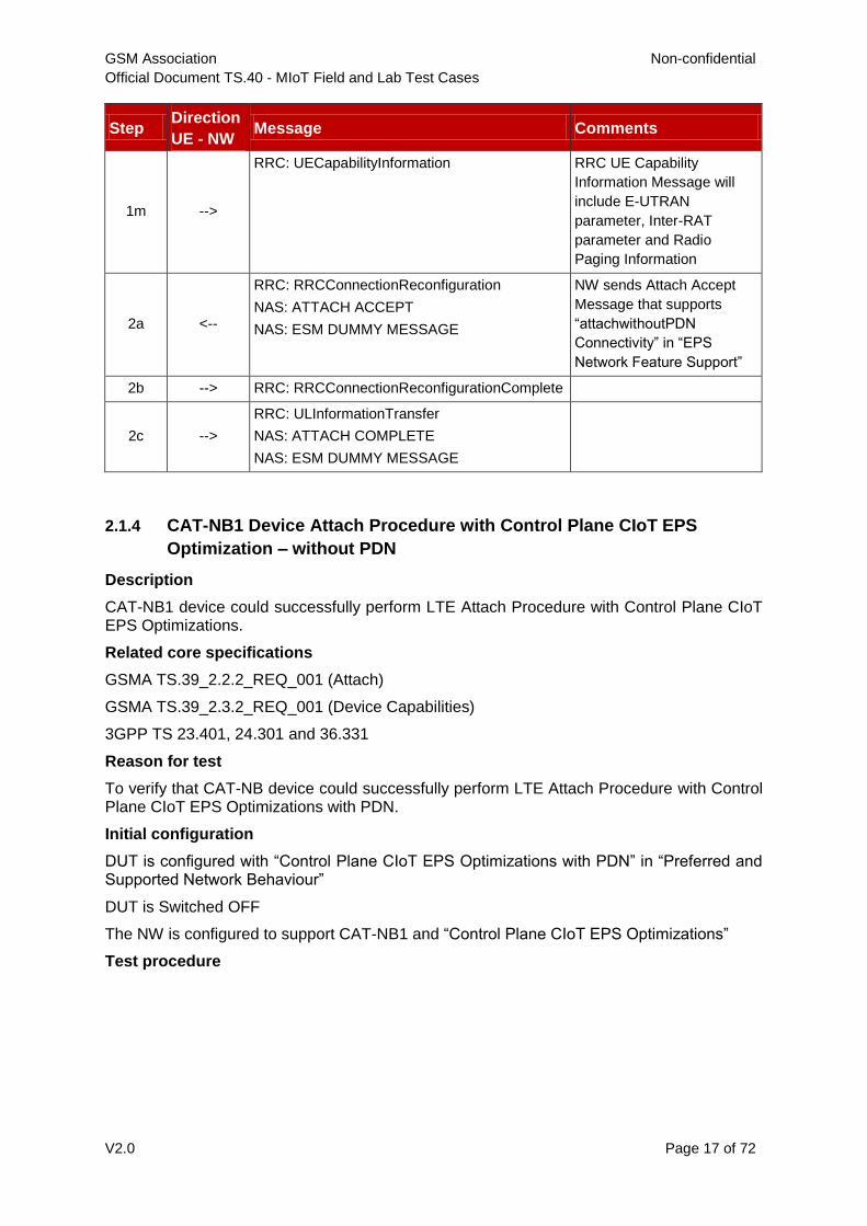
Step Direction
UE - NW Message Comments
1m -->
RRC: UECapabilityInformation RRC UE Capability
Information Message will
include E-UTRAN
parameter, Inter-RAT
parameter and Radio
Paging Information
2a <--
RRC: RRCConnectionReconfiguration
NAS: ATTACH ACCEPT
NAS: ESM DUMMY MESSAGE
NW sends Attach Accept
Message that supports
“attachwithoutPDN
Connectivity” in “EPS
Network Feature Support”
2b --> RRC: RRCConnectionReconfigurationComplete
2c -->
RRC: ULInformationTransfer
NAS: ATTACH COMPLETE
NAS: ESM DUMMY MESSAGE
2.1.4 CAT-NB1 Device Attach Procedure with Control Plane CIoT EPS
Optimization – without PDN
Description
CAT-NB1 device could successfully perform LTE Attach Procedure with Control Plane CIoT EPS Optimizations.
Related core specifications
GSMA TS.39_2.2.2_REQ_001 (Attach)
GSMA TS.39_2.3.2_REQ_001 (Device Capabilities)
3GPP TS 23.401, 24.301 and 36.331
Reason for test
To verify that CAT-NB device could successfully perform LTE Attach Procedure with Control Plane CIoT EPS Optimizations with PDN.
Initial configuration
DUT is configured with “Control Plane CIoT EPS Optimizations with PDN” in “Preferred and Supported Network Behaviour”
DUT is Switched OFF
The NW is configured to support CAT-NB1 and “Control Plane CIoT EPS Optimizations”
Test procedure

GSM Association Non-confidential
Official Document TS.40 - MIoT Field and Lab Test Cases
V2.0 Page 18 of 72
Step Test procedure Expected behaviour
1 Switch on DUT DUT in EMM_IDLE mode reads SIB2-NB;
set up RRC connection and sends Attach
Request message indicating support of
“Control Plane CIoT EPS Optimization”
together with PDN CONNECTIVITY
REQUEST Message.
2
Verify the DUT sends Attach
AcceptComplete after reception of Attach
Accept message from NW
Upon reception of Attach Accept message
from NW DUT successfully completes
attach procedure by sending Attach
Complete Message
Example message flow:
Step Direction
UE - NW Message Comments
1a --> RRC: RRCConnection Request-NB
After DUT has read SIB2-
NB to verify that “Control
Plane CIoT EPS
Optimizations” is broadcast
in EUTRAN Cell it sends
RRC Connection Request
1b <-- RRC: RRCConnectionSetup-NB
1c -->
RRC: RRCConnectionSetupComplete
NAS: ATTACH REQUEST
NAS: ESM DUMMY MESSAGE
Attach Request message
indicates support of “Control
Plane CIoT EPS
Optimization”
1d <-- RRC: DLInformationTransfer-NB
NAS: IDENTITY REQUEST
1e --> RRC: ULInformationTransfer-NB
NAS: IDENTITY RESPONSE
1f <-- RRC: DLInformationTransfer-NB
NAS: AUTHENTICATION REQUEST
1g --> RRC: ULInformationTransfer-NB
NAS: AUTHENTICATION RESPONSE
1h <-- RRC: DLInformationTransfer-NB
NAS: SECURITY MODE COMMAND
1i --> RRC: ULInformationTransfer-NB
NAS: SECURITY MODE COMPLETE
2a <--
RRC: DLInformationTransfer-NB
NAS: ATTACH ACCEPT
NAS: ESM DUMMY MESSAGE
2b -->
RRC: ULInformationTransfer-NB
NAS: ATTACH COMPLETE
NAS: ESM DUMMY MESSAGE
2c <-- RRC: RRCConnectionRelease-NB

GSM Association Non-confidential
Official Document TS.40 - MIoT Field and Lab Test Cases
V2.0 Page 19 of 72
2.1.5 CAT-NB1 Device Attach Procedure with Control Plane CIoT EPS
Optimization – with PDN
Description
CAT-NB1 device could successfully perform LTE Attach Procedure with Control Plane CIoT EPS Optimizations.
Related core specifications
GSMA TS.39_2.2.2_REQ_001 (Attach)
GSMA TS.39_2.3.2_REQ_001 (Device Capabilities)
3GPP TS 23.401, 24.301 and 36.331
Reason for test
To verify that CAT-NB1 device could successfully perform LTE Attach Procedure with Control Plane CIoT EPS Optimizations with PDN.
Initial configuration
DUT is configured with “Control Plane CIoT EPS Optimizations with PDN” in “Preferred and Supported Network Behaviour”
DUT is Switched OFF
The NW is configured to support CAT-NB1 and “Control Plane CIoT EPS Optimizations”
Test procedure
Step Test procedure Expected behaviour
1 Switch on DUT DUT in EMM_IDLE mode reads SIB2-NB;
set up RRC connection and sends Attach
Request message indicating support of
“Control Plane CIoT EPS Optimization”
together with PDN CONNECTIVITY
REQUEST Message.
2
Verify the DUT sends Attach
AcceptComplete after reception of Attach
Accept message from NW
Upon reception of Attach Accept message
from NW DUT successfully completes
attach procedure by sending Attach
Complete Message
GSM Association Non-confidential
Official Document TS.40 - MIoT Field and Lab Test Cases
V2.0 Page 20 of 72
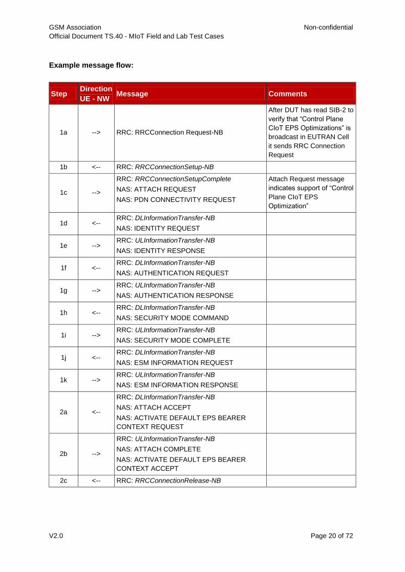
Example message flow:
Step Direction
UE - NW Message Comments
1a --> RRC: RRCConnection Request-NB
After DUT has read SIB-2 to
verify that “Control Plane
CIoT EPS Optimizations” is
broadcast in EUTRAN Cell
it sends RRC Connection
Request
1b <-- RRC: RRCConnectionSetup-NB
1c -->
RRC: RRCConnectionSetupComplete
NAS: ATTACH REQUEST
NAS: PDN CONNECTIVITY REQUEST
Attach Request message
indicates support of “Control
Plane CIoT EPS
Optimization”
1d <-- RRC: DLInformationTransfer-NB
NAS: IDENTITY REQUEST
1e --> RRC: ULInformationTransfer-NB
NAS: IDENTITY RESPONSE
1f <-- RRC: DLInformationTransfer-NB
NAS: AUTHENTICATION REQUEST
1g --> RRC: ULInformationTransfer-NB
NAS: AUTHENTICATION RESPONSE
1h <-- RRC: DLInformationTransfer-NB
NAS: SECURITY MODE COMMAND
1i --> RRC: ULInformationTransfer-NB
NAS: SECURITY MODE COMPLETE
1j <-- RRC: DLInformationTransfer-NB
NAS: ESM INFORMATION REQUEST
1k --> RRC: ULInformationTransfer-NB
NAS: ESM INFORMATION RESPONSE
2a <--
RRC: DLInformationTransfer-NB
NAS: ATTACH ACCEPT
NAS: ACTIVATE DEFAULT EPS BEARER
CONTEXT REQUEST
2b -->
RRC: ULInformationTransfer-NB
NAS: ATTACH COMPLETE
NAS: ACTIVATE DEFAULT EPS BEARER
CONTEXT ACCEPT
2c <-- RRC: RRCConnectionRelease-NB

GSM Association Non-confidential
Official Document TS.40 - MIoT Field and Lab Test Cases
V2.0 Page 21 of 72
2.1.6 CAT-NB1 Device Attach Procedure with User Plane CIoT EPS
Optimization – without PDN
Description
CAT-NB1 device could successfully perform LTE Attach Procedure with User Plane CIoT EPS Optimizations without PDN connection.
Related core specifications
GSMA TS.39_2.1.2_REQ_001 (Cell Selection Procedure)
GSMA TS.39_2.2.2_REQ_001 (Attach)
GSMA TS.39_2.3.2_REQ_001 (Device Capabilities)
3GPP TS 23.401, 24.301 and 36.331
Reason for test
To verify that CAT-NB1 device could successfully perform LTE Attach Procedure with User Plane CIoT EPS Optimizations without PDN.
Initial configuration
DUT is configured with “User Plane CIoT EPS Optimizations without PDN” in “Preferred and Supported Network Behaviour”
DUT is Switched OFF
The NW is configured to support CAT-NB1 and “User Plane CIoT EPS Optimizations without PDN-Connectivity”
Test procedure
Step Test procedure Expected behaviour
1 Switch on DUT DUT in EMM_IDLE mode reads SIB2-NB;
set up RRC connection and sends Attach
Request message indicating support of
“User Plane CIoT EPS Optimization”
together with ESM DUMMY Message.
2
Verify the DUT sends Attach
AcceptComplete after reception of Attach
Accept message from NW
Upon reception of Attach Accept message
from NW DUT successfully completes
attach procedure by sending Attach
Complete Message
Example message flow:
Step Direction
UE - NW Message Comments
1a --> RRC: RRCConnection Request-NB
After DUT has read SIB2-
NB to verify that “User
Plane CIoT EPS
Optimizations” and “EPS
Attach without PDN
Connectivity” is
broadcasted in EUTRAN
Cell
GSM Association Non-confidential
Official Document TS.40 - MIoT Field and Lab Test Cases
V2.0 Page 22 of 72
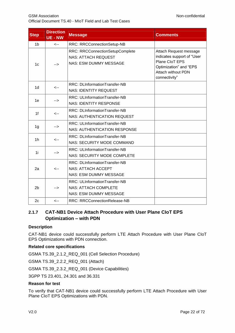
Step Direction
UE - NW Message Comments
1b <-- RRC: RRCConnectionSetup-NB
1c -->
RRC: RRCConnectionSetupComplete
NAS: ATTACH REQUEST
NAS: ESM DUMMY MESSAGE
Attach Request message
indicates support of “User
Plane CIoT EPS
Optimization” and “EPS
Attach without PDN
connectivity”
1d <-- RRC: DLInformationTransfer-NB
NAS: IDENTITY REQUEST
1e --> RRC: ULInformationTransfer-NB
NAS: IDENTITY RESPONSE
1f <-- RRC: DLInformationTransfer-NB
NAS: AUTHENTICATION REQUEST
1g --> RRC: ULInformationTransfer-NB
NAS: AUTHENTICATION RESPONSE
1h <-- RRC: DLInformationTransfer-NB
NAS: SECURITY MODE COMMAND
1i --> RRC: ULInformationTransfer-NB
NAS: SECURITY MODE COMPLETE
2a <--
RRC: DLInformationTransfer-NB
NAS: ATTACH ACCEPT
NAS: ESM DUMMY MESSAGE
2b -->
RRC: ULInformationTransfer-NB
NAS: ATTACH COMPLETE
NAS: ESM DUMMY MESSAGE
2c <-- RRC: RRCConnectionRelease-NB
2.1.7 CAT-NB1 Device Attach Procedure with User Plane CIoT EPS
Optimization – with PDN
Description
CAT-NB1 device could successfully perform LTE Attach Procedure with User Plane CIoT EPS Optimizations with PDN connection.
Related core specifications
GSMA TS.39_2.1.2_REQ_001 (Cell Selection Procedure)
GSMA TS.39_2.2.2_REQ_001 (Attach)
GSMA TS.39_2.3.2_REQ_001 (Device Capabilities)
3GPP TS 23.401, 24.301 and 36.331
Reason for test
To verify that CAT-NB1 device could successfully perform LTE Attach Procedure with User Plane CIoT EPS Optimizations with PDN.
GSM Association Non-confidential
Official Document TS.40 - MIoT Field and Lab Test Cases
V2.0 Page 23 of 72
Initial configuration
DUT is configured with “User Plane CIoT EPS Optimizations with PDN” in “Preferred and Supported Network Behaviour”
DUT is Switched OFF
The NW is configured to support CAT-NB1 and “User Plane CIoT EPS Optimizations”
Test procedure
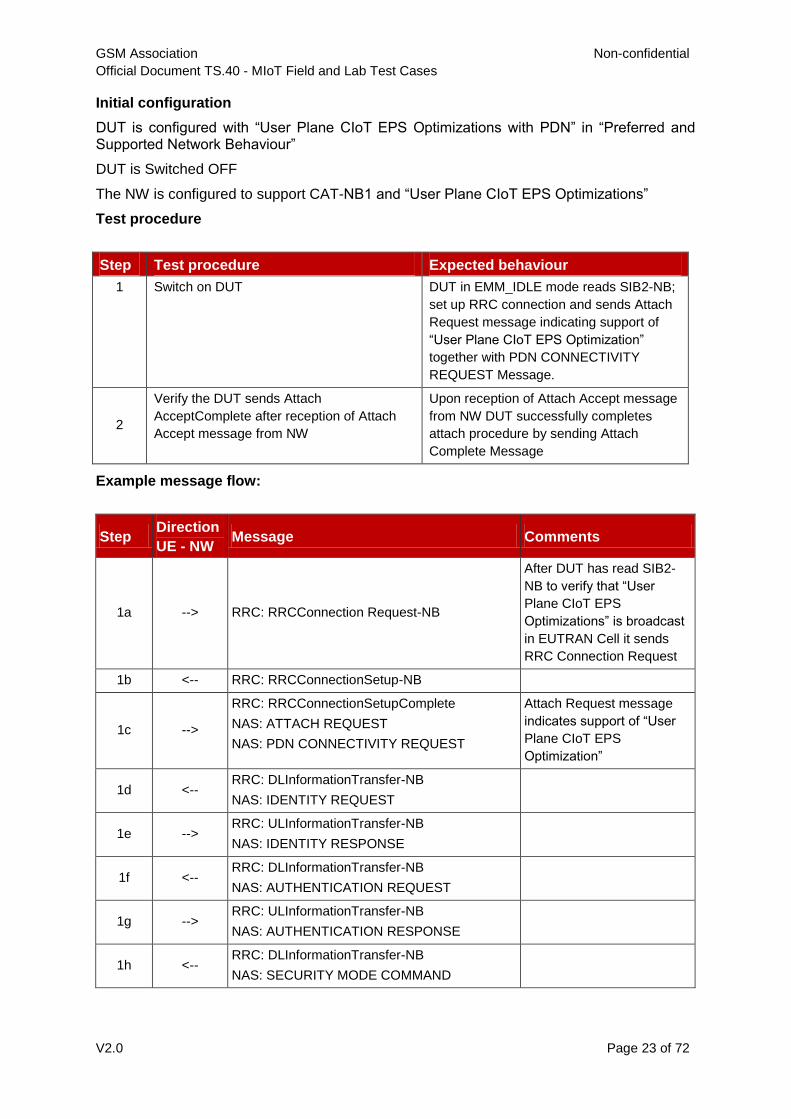
Step Test procedure Expected behaviour
1 Switch on DUT DUT in EMM_IDLE mode reads SIB2-NB;
set up RRC connection and sends Attach
Request message indicating support of
“User Plane CIoT EPS Optimization”
together with PDN CONNECTIVITY
REQUEST Message.
2
Verify the DUT sends Attach
AcceptComplete after reception of Attach
Accept message from NW
Upon reception of Attach Accept message
from NW DUT successfully completes
attach procedure by sending Attach
Complete Message
Example message flow:
Step Direction
UE - NW Message Comments
1a --> RRC: RRCConnection Request-NB
After DUT has read SIB2-
NB to verify that “User
Plane CIoT EPS
Optimizations” is broadcast
in EUTRAN Cell it sends
RRC Connection Request
1b <-- RRC: RRCConnectionSetup-NB
1c -->
RRC: RRCConnectionSetupComplete
NAS: ATTACH REQUEST
NAS: PDN CONNECTIVITY REQUEST
Attach Request message
indicates support of “User
Plane CIoT EPS
Optimization”
1d <-- RRC: DLInformationTransfer-NB
NAS: IDENTITY REQUEST
1e --> RRC: ULInformationTransfer-NB
NAS: IDENTITY RESPONSE
1f <-- RRC: DLInformationTransfer-NB
NAS: AUTHENTICATION REQUEST
1g --> RRC: ULInformationTransfer-NB
NAS: AUTHENTICATION RESPONSE
1h <-- RRC: DLInformationTransfer-NB
NAS: SECURITY MODE COMMAND
GSM Association Non-confidential
Official Document TS.40 - MIoT Field and Lab Test Cases
V2.0 Page 24 of 72
Step Direction
UE - NW Message Comments
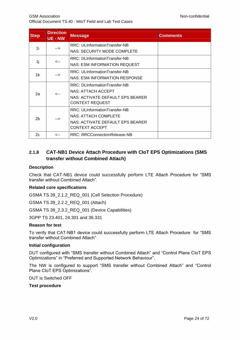
1i --> RRC: ULInformationTransfer-NB
NAS: SECURITY MODE COMPLETE
1j <-- RRC: DLInformationTransfer-NB
NAS: ESM INFORMATION REQUEST
1k --> RRC: ULInformationTransfer-NB
NAS: ESM INFORMATION RESPONSE
2a <--
RRC: DLInformationTransfer-NB
NAS: ATTACH ACCEPT
NAS: ACTIVATE DEFAULT EPS BEARER
CONTEXT REQUEST
2b -->
RRC: ULInformationTransfer-NB
NAS: ATTACH COMPLETE
NAS: ACTIVATE DEFAULT EPS BEARER
CONTEXT ACCEPT
2c <-- RRC: RRCConnectionRelease-NB
2.1.8 CAT-NB1 Device Attach Procedure with CIoT EPS Optimizations (SMS
transfer without Combined Attach)
Description
Check that CAT-NB1 device could successfully perform LTE Attach Procedure for “SMS transfer without Combined Attach”.
Related core specifications
GSMA TS.39_2.1.2_REQ_001 (Cell Selection Procedure)
GSMA TS.39_2.2.2_REQ_001 (Attach)
GSMA TS.39_2.3.2_REQ_001 (Device Capabilities)
3GPP TS 23.401, 24.301 and 36.331
Reason for test
To verify that CAT-NB1 device could successfully perform LTE Attach Procedure for “SMS transfer without Combined Attach”
Initial configuration
DUT configured with “SMS transfer without Combined Attach” and “Control Plane CIoT EPS Optimizations” in “Preferred and Supported Network Behaviour”.
The NW is configured to support “SMS transfer without Combined Attach” and “Control Plane CIoT EPS Optimizations”.
DUT is Switched OFF
Test procedure
GSM Association Non-confidential
Official Document TS.40 - MIoT Field and Lab Test Cases
V2.0 Page 25 of 72
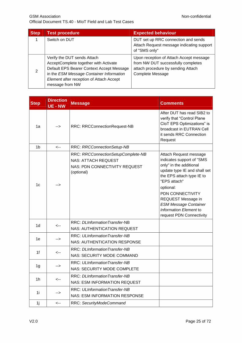
Step Test procedure Expected behaviour
1 Switch on DUT DUT set up RRC connection and sends
Attach Request message indicating support
of "SMS only"
2
Verify the DUT sends Attach
AcceptComplete together with Activate
Default EPS Bearer Context Accept Message
in the ESM Message Container Information
Element after reception of Attach Accept
message from NW
Upon reception of Attach Accept message
from NW DUT successfully completes
attach procedure by sending Attach
Complete Message
Step Direction
UE - NW Message Comments
1a --> RRC: RRCConnectionRequest-NB
After DUT has read SIB2 to
verify that “Control Plane
CIoT EPS Optimizations” is
broadcast in EUTRAN Cell
it sends RRC Connection
Request
1b <-- RRC: RRCConnectionSetup-NB
1c -->
RRC: RRCConnectionSetupComplete-NB
NAS: ATTACH REQUEST
NAS: PDN CONNECTIVITY REQUEST
(optional)
Attach Request message
indicates support of "SMS
only" in the additional
update type IE and shall set
the EPS attach type IE to
"EPS attach"
optional:
PDN CONNECTIVITY
REQUEST Message in
ESM Message Container
Information Element to
request PDN Connectivity
1d <-- RRC: DLInformationTransfer-NB
NAS: AUTHENTICATION REQUEST
1e --> RRC: ULInformationTransfer-NB
NAS: AUTHENTICATION RESPONSE
1f <-- RRC: DLInformationTransfer-NB
NAS: SECURITY MODE COMMAND
1g --> RRC: ULInformationTransfer-NB
NAS: SECURITY MODE COMPLETE
1h <-- RRC: DLInformationTransfer-NB
NAS: ESM INFORMATION REQUEST
1i --> RRC: ULInformationTransfer-NB
NAS: ESM INFORMATION RESPONSE
1j <-- RRC: SecurityModeCommand

GSM Association Non-confidential
Official Document TS.40 - MIoT Field and Lab Test Cases
V2.0 Page 26 of 72
Step Direction
UE - NW Message Comments
1k --> RRC: SecurityModeComplete
1l <-- RRC: UECapabilityEnquiry
1m -->
RRC: UECapabilityInformation RRC UE Capability
Information Message will
include E-UTRAN
parameter, Inter-RAT
parameter and Radio
Paging Information
2a <--
RRC: RRCConnectionReconfiguration-NB
NAS: ATTACH ACCEPT
NAS: ACTIVATE DEFAULT EPS BEARER
CONTEXT REQUEST (optional)
2b --> RRC:
RRCConnectionReconfigurationComplete-NB
2c -->
RRC: ULInformationTransfer
NAS: ATTACH COMPLETE
NAS: ACTIVATE DEFAULT EPS BEARER
CONTEXT ACCEPT (optional)
Optional:
Activate Default EPS
Bearer Context Accept
Message in the ESM
Message Container
Information Element
2.1.9 Attach Procedure / Reject / No suitable cell in TA (EMM cause #15)
Description
Check an CAT-M1 or CAT-NB1 device behaviour on the reject message with cause 15 ‘No suitable cells in TA’ in an MIoT environment that is incompatible with DUTs’ CIoT EPS optimisation.
Related core specifications
GSMA TS.39_2.1.2_REQ_001 (Cell Selection Procedure)
GSMA TS.39_2.2.2_REQ_001 (Attach)
GSMA TS.39_2.3.2_REQ_001 (Device Capabilities)
GSMA TS.39_2.2.2_REQ_005 (Reject Cause)
3GPP TS 23.401, 24.301 and 36.331
Reason for test
To verify that CAT-M1 or CAT-NB1 DUT behaves correctly on a reject message ‘‘No suitable cell in TA” from the E-UTRA cell. The DUT shall indicate the loss of service with an appropriate error message (e.g. limited service).
Initial configuration
DUT and NW configured “CIoT EPS Optimizations” are not compatible.
DUT is Switched OFF
Test procedure
GSM Association Non-confidential
Official Document TS.40 - MIoT Field and Lab Test Cases
V2.0 Page 27 of 72
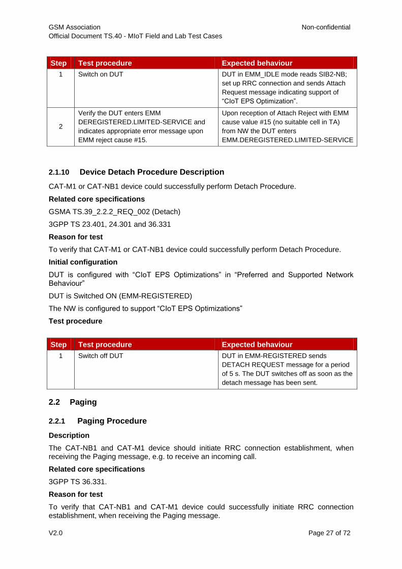
Step Test procedure Expected behaviour
1 Switch on DUT DUT in EMM_IDLE mode reads SIB2-NB;
set up RRC connection and sends Attach
Request message indicating support of
“CIoT EPS Optimization”.
2
Verify the DUT enters EMM
DEREGISTERED.LIMITED-SERVICE and
indicates appropriate error message upon
EMM reject cause #15.
Upon reception of Attach Reject with EMM
cause value #15 (no suitable cell in TA)
from NW the DUT enters
EMM.DEREGISTERED.LIMITED-SERVICE
2.1.10 Device Detach Procedure Description
CAT-M1 or CAT-NB1 device could successfully perform Detach Procedure.
Related core specifications
GSMA TS.39_2.2.2_REQ_002 (Detach)
3GPP TS 23.401, 24.301 and 36.331
Reason for test
To verify that CAT-M1 or CAT-NB1 device could successfully perform Detach Procedure.
Initial configuration
DUT is configured with “CIoT EPS Optimizations” in “Preferred and Supported Network Behaviour”
DUT is Switched ON (EMM-REGISTERED)
The NW is configured to support “CIoT EPS Optimizations”
Test procedure
Step Test procedure Expected behaviour
1 Switch off DUT DUT in EMM-REGISTERED sends
DETACH REQUEST message for a period
of 5 s. The DUT switches off as soon as the
detach message has been sent.
2.2 Paging
2.2.1 Paging Procedure
Description
The CAT-NB1 and CAT-M1 device should initiate RRC connection establishment, when receiving the Paging message, e.g. to receive an incoming call.
Related core specifications
3GPP TS 36.331.
Reason for test
To verify that CAT-NB1 and CAT-M1 device could successfully initiate RRC connection establishment, when receiving the Paging message.
GSM Association Non-confidential
Official Document TS.40 - MIoT Field and Lab Test Cases
V2.0 Page 28 of 72
Initial configuration
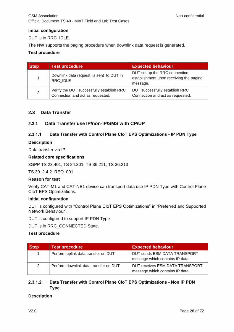
DUT is in RRC_IDLE.
The NW supports the paging procedure when downlink data request is generated.
Test procedure
Step Test procedure Expected behaviour
1 Downlink data request is sent to DUT in
RRC_IDLE
DUT set up the RRC connection
establishment upon receiving the paging
message.
2 Verify the DUT successfully establish RRC
Connection and act as requested.
DUT successfully establish RRC
Connection and act as requested.
2.3 Data Transfer
2.3.1 Data Transfer use IP/non-IP/SMS with CP/UP
2.3.1.1 Data Transfer with Control Plane CIoT EPS Optimizations - IP PDN Type
Description
Data transfer via IP
Related core specifications
3GPP TS 23.401, TS 24.301, TS 36.211, TS 36.213
TS.39_2.4.2_REQ_001
Reason for test
Verify CAT-M1 and CAT-NB1 device can transport data use IP PDN Type with Control Plane CIoT EPS Optimizations.
Initial configuration
DUT is configured with “Control Plane CIoT EPS Optimizations” in “Preferred and Supported Network Behaviour”.
DUT is configured to support IP PDN Type
DUT is in RRC_CONNECTED State.
Test procedure
Step Test procedure Expected behaviour
1 Perform uplink data transfer on DUT DUT sends ESM DATA TRANSPORT
message which contains IP data
2 Perform downlink data transfer on DUT DUT receives ESM DATA TRANSPORT
message which contains IP data
2.3.1.2 Data Transfer with Control Plane CIoT EPS Optimizations - Non IP PDN
Type
Description

GSM Association Non-confidential
Official Document TS.40 - MIoT Field and Lab Test Cases
V2.0 Page 29 of 72
Data transfer via non-IP
Related core specifications
3GPP TS 23.401,3GPP TS 24.301, TS 36.211, TS 36.213
TS.39_2.4.2_REQ_001
Reason for test
Verify CAT-M1 and CAT-NB1 device can transport data use Non IP PDN Type with Control Plane CIoT EPS Optimizations.
Initial configuration
DUT is configured with “Control Plane CIoT EPS Optimizations” in “Preferred and Supported Network Behaviour”.
DUT is configured to support Non IP PDN Type
DUT is in RRC_CONNECTED State.
Test procedure
Step Test procedure Expected behaviour
1 Perform uplink data transfer on DUT DUT sends ESM DATA TRANSPORT
message which contains Non IP data
2 Perform downlink data transfer on DUT DUT receives ESM DATA TRANSPORT
message which contains Non IP data
2.3.1.3 Data Transfer with User Plane CIoT EPS Optimizations - IP PDN Type
Description
Data transfer via IP
Related core specifications
3GPP TS 23.401,3GPP TS 24.301, TS 36.211, TS 36.213
TS.39_2.4.2_REQ_001
Reason for test
Verify CAT-M1 and CAT-NB1 device can transport data use IP PDN Type with User Plane CIoT EPS Optimizations.
Initial configuration
DUT is configured with “User Plane CIoT EPS Optimizations” in “Preferred and Supported Network Behaviour”.
DUT is configured to support IP PDN Type
DUT is in RRC_CONNECTED State.
Test procedure
Step Test procedure Expected behaviour
1 Perform uplink data transfer on DUT DUT sends ESM DATA TRANSPORT
message which contains IP data

GSM Association Non-confidential
Official Document TS.40 - MIoT Field and Lab Test Cases
V2.0 Page 30 of 72
2 Perform downlink data transfer on DUT DUT receives ESM DATA TRANSPORT
message which contains IP data
2.3.1.4 Data Transfer with User Plane CIoT EPS Optimizations - Non IP PDN Type
Description
Data transfer via non-IP
Related core specifications
3GPP TS 23.401,3GPP TS 24.301, TS 36.211, TS 36.213
TS.39_2.4.2_REQ_001
Reason for test
Verify CAT-M1 and CAT-NB1 device can transport data use Non IP PDN Type with User Plane CIoT EPS Optimizations.
Initial configuration
DUT is configured with “User Plane CIoT EPS Optimizations” in “Preferred and Supported Network Behaviour”.
DUT is configured to support Non IP PDN Type
DUT is in RRC_CONNECTED State.
Test procedure
Step Test procedure Expected behaviour
1 Perform uplink data transfer on DUT DUT sends ESM DATA TRANSPORT
message which contains Non IP data
2 Perform downlink data transfer on DUT DUT receives ESM DATA TRANSPORT
message which contains Non IP data
2.3.1.5 Data Transfer with Control Plane CIoT EPS Optimizations - SMS
Description
SMS message transfer
Related core specifications
3GPP TS 24.301, TS 23.401, 3GPP TS 23.040
Reason for test
Verify CAT-M1 and CAT-NB1 device can transport and receive SMS message with Control Plane CIoT EPS Optimizations.
Initial configuration
DUT and Client 1 are configured with “Control Plane CIoT EPS Optimizations” in “Preferred and Supported Network Behaviour”.
Client 1 indicates the same UE category as DUT.
DUT is in RRC_IDLE State.
Test procedure

GSM Association Non-confidential
Official Document TS.40 - MIoT Field and Lab Test Cases
V2.0 Page 31 of 72
Step Test procedure Expected behaviour
1 Send the SMS message from DUT to Client
1
DUT sends Control Plane Service
Request message which contains SMS
message
SMS is successfully received on Client 1.
2 Send the SMS message from Client 1 to
DUT
SMS is successfully received on DUT.
2.3.2 Suspend Resume
2.3.2.1 CAT-M1 Device Suspend-Resume procedure with User Plane CIoT EPS
Optimization
Description
CAT-M1 device could successfully perform the suspend-resume procedure. After resuming the RRC connection the CAT-M1 device shall re-activate security and re-establish the DRB connection
Related core specifications
GSMA TS.39_2.6.2_REQ_001 (Suspend)
GSMA TS.39_2.6.2_REQ_002 (Resume)
3GPP TS 36.331
Reason for test
To verify that CAT-M1 device could successfully perform the suspend and resume procedure. After resuming the RRC connection the CAT-M1 device shall re-activate security and re-establish the DRB connection.
Initial configuration
DUT is configured with “User Plane CIoT EPS Optimizations” in “Preferred and Supported Network Behaviour”
DUT is Switched ON
DUT has DRB connection established
The NW is configured to support CAT-M1 and “User Plane CIoT EPS Optimizations”
Test procedure

GSM Association Non-confidential
Official Document TS.40 - MIoT Field and Lab Test Cases
V2.0 Page 32 of 72
Step Test procedure Expected behaviour
1 Trigger the NW to send an
RRCConnectionRelease Message including
the “resumeIdentity” and “release cause:
rrc-Suspend”
DUT releases RRC connection and moves
into RRC_IDLE state. (DUT stores
resumeIdentity during RC connection
release)
2
Trigger the DUT to send some user data in
UL
DUT transmits RRCConnectionResume
Request Message with “resumeIdentity”
and including information needed by the
eNodeB to access the DUT's stored AS
Context.
Security is fully resumed on DUT side after reception and processing of RRCConnectionResume Message.
Some EPS bearer can’t be resumed by the NW, in that case eNB will reconfigure the radio bearers.
UL Data from DUT is sent
Example message flow:
Step Direction
UE - NW Message Comments
1a <--
RRC: RRCConnectionRelease The NW transmits an
RRCConnectionRelease
message including
“resumeIdentity” and “rrc-
Suspend” as releaseCause.
2a -->
RRC: RRCConnectionResumeRequest DUT transmits an
RRCConnectionResumeRequ
est message including the
“resumeIdentity” and “AS
security context” stored in step
1a
2b <-- RRC: RRCConnectionResume
2c --> RRC: RRCConnectionResumeComplete
2.3.2.2 CAT-NB1 Device Suspend-Resume procedure with User Plane CIoT EPS
Optimization
Description
CAT-NB1 device could successfully perform the suspend-resume procedure.
Related core specifications
GSMA TS.39_2.6.2_REQ_001
GSMA TS.39_2.6.2_REQ_002
3GPP TS 36.331
Reason for test

GSM Association Non-confidential
Official Document TS.40 - MIoT Field and Lab Test Cases
V2.0 Page 33 of 72
To verify that CAT-NB1 device could successfully perform the suspend and resume procedure.
Initial configuration
DUT is configured with “User Plane CIoT EPS Optimizations” in “Preferred and Supported Network Behaviour”
DUT is Switched ON
The NW is configured to support CAT-NB1 and “User Plane CIoT EPS Optimizations”
Test procedure
Step Test procedure Expected behaviour
1 Trigger the NW to send an
RRCConnectionRelease-NB Message
including the “resumeIdentity” and “release
cause: rrc-Suspend”
DUT releases RRC connection and moves
into RRC_IDLE state. (DUT stores
resumeIdentity during RC connection
release)
2
Trigger the DUT to send some user data in
UL
DUT transmits
RRCConnectionResumeRequest-NB
Message with “resumeIdentity” and
including information needed by the eNB to
access the DUT's stored AS Context.
Some EPS bearer can’t be resumed by the network, in that case eNodeB will reconfigures the radio bearers
UL Data from DUT is sent
Example message flow:
Step Direction
UE - NW Message Comments
1a
<-- RRC: RRCConnectionRelease-NB The NW transmits an
RRCConnectionRelease-NB
message including
“resumeIdentity” and “rrc-
Suspend” as releaseCause.
2a
--> RRC: RRCConnectionResumeRequest-NB DUT transmits an
RRCConnectionResumeRequ
est-NB message including the
“resumeIdentity” and “AS
security context” stored in step
1a
2b <-- RRC: RRCConnectionResume-NB
2c --> RRC: RRCConnectionResumeComplete-NB

GSM Association Non-confidential
Official Document TS.40 - MIoT Field and Lab Test Cases
V2.0 Page 34 of 72
2.3.3 Serving PLMN Rate Control / APN Rate Control
2.3.3.1 Serving PLMN Rate Control
Description
CAT-NB1 device could support Serving PLMN Rate Control.
Related core specifications
GSMA TS.39_2.7.1_REQ_001 (Serving PLMN Rate Control)
3GPP TS 23.401, 24.301
Reason for test
To verify that CAT-NB1 device could support Serving PLMN Rate Control .
Initial configuration
DUT is configured to support Serving PLMN Rate Control;
DUT is Switched OFF
DUT attach Procedure with Control Plane CIoT EPS
The NW is configured to support CAT NB1 and “Serving PLMN Rate Control ”
Test procedure
Step Test procedure Expected behaviour
1 Switch on DUT DUT is in EMM-IDLE mode; set up RRC
connection and sends Attach Request
message indicating support of “Control
Plane CIoT EPS” together with PDN
CONNECTIVITY REQUEST Message.
2 Wait until the DUT sends Attach Complete
message to NW, verify the DUT receive of
ACTIVATE DEFAULT EPS BEARER
CONTEXT REQUEST message from NW,
which including “serving PLMN rate control”
parameter
DUT receive of ACTIVATE DEFAULT
EPS BEARER CONTEXT REQUEST
message from NW, which including
“serving PLMN rate control” parameter,
such as:10 . (It indicate the maximum
number of uplink ESM DATA
TRANSPORT messages including User
data container IEs , which indicate that the
DUT is allowed to send via a PDN
connection per 6 minute interval is 10 (see
3GPP TS 23.401)).
3 DUT send the uplink user data. DUT send the uplink user data by ESM
DATA TRANSPORT message via the
control plan.
4 Verify the DUT limit the rate once the
number of ESM DATA TRANSPORT
message is more than the “serving PLMN
rate control” parameter, to comply with the
serving PLMN policy provided by the
network.
once the number of ESM DATA
TRANSPORT message is more than the
“serving PLMN rate control” parameter,
DUT can’t send the uplink user data.

GSM Association Non-confidential
Official Document TS.40 - MIoT Field and Lab Test Cases
V2.0 Page 35 of 72
2.3.3.2 APN Rate Control
Description
CAT-NB1 device could support APN Rate Control.
Related core specifications
GSMA TS.39_2.7.2_REQ_002 (APN Rate Control)
3GPP TS 24.008, 23.401 and 24.301
Reason for test
To verify that CAT-NB1 device could support APN Rate Control .
Initial configuration
DUT is configured to support APN Rate Control;
DUT is Switched OFF
DUT attach Procedure
The NW is configured to support APN Rate Control
Test procedure
Step Test procedure Expected behaviour
1 Switch on DUT DUT is in EMM-IDLE mode; set up RRC
connection and sends Attach Request
message with PDN CONNECTIVITY
REQUEST Message. The PDN
CONNECTIVITY REQUEST Message
indicating support of “APN rate control
support indicator”.
2 Wait until the DUT sends Attach Complete
message to NW, verify the DUT receive of
ACTIVATE DEFAULT EPS BEARER
CONTEXT REQUEST message from NW,
which including “APN rate control”
parameter
DUT receive of ACTIVATE DEFAULT
EPS BEARER CONTEXT REQUEST
message from NW, which including “APN
rate control ” parameter, such as:10 . (
It indicate the maximum allowed limit of
uplink user data related to the
corresponding APN in accordance with
3GPP TS 23.401 .
3 DUT send the uplink user data. DUT send the uplink user data by ESM
DATA TRANSPORT message via the
control plan.
4 Verify the DUT limit the rate once the
number of ESM DATA TRANSPORT
message is more than the “APN rate
control” parameter, to comply with the
APN rate control policy provided by the
network.
once the number of ESM DATA
TRANSPORT message is more than the
“APN rate control” parameter, DUT can’t
send the uplink user data.

GSM Association Non-confidential
Official Document TS.40 - MIoT Field and Lab Test Cases
V2.0 Page 36 of 72
2.4 Mobility Performance
2.4.1 IDLE-Mode Mobility
2.4.1.1 CAT-M1 Device Cell Reselection Procedure
Description
CAT-M1 device performs Cell Reselection Procedure with CIoT EPS Optimizations when re-selection criteria and ranking criteria are met.
Related core specifications
GSMA TS.39_2.5.1_REQ_001 (Cell Reselection)
3GPP TS 36.304, TS 36.300 and TS 36.331
Reason for test
To verify that CAT-M1 device could successfully perform Cell Reselection to new cell.
Initial configuration
DUT is configured with “CIoT EPS Optimizations” in “Preferred and Supported Network Behaviour”
DUT is in RRC_IDLE state
Two EUTRAN cells (Cell 1 and Cell 2) are configured to support CAT M1 and “CIoT EPS Optimizations”
Test procedure
Step Test procedure Expected behaviour
1 Change the radio conditions that Cell 1
(serving cell) becomes unsuitable and Cell 2
(neighbour cell) becomes visible.
DUT reselects to Cell 2 and starts to read
System Information to check that “CIoT
EPS Optimizations are broadcasted.
2 Verify the DUT is attached to new Cell 2 DUT performs TAU procedure in Cell 2 and
releases RRC connection.
2.4.1.2 CAT-NB1 Device Intra-Frequency Cell Reselection
Description
CAT-NB1 device performs the cell reselection within the Intra-frequency NB-IoT cells under RRC-Idle mode when serving cell becomes unsuitable.
Related core specifications
GSMA TS.39_2.5.1_REQ_001 (Cell Reselection)
3GPP TS 36.304, TS 36.300, and TS 36.331
Reason for test
To verify that CAT-NB1 device successfully performs the Cell Reselection within the Intra-frequency NB-IoT cells under RRC-Idle mode.
Initial configuration
DUT is configured with “CIoT EPS Optimizations” in “Preferred and Supported Network Behaviour”
DUT is in RRC_IDLE on serving Cell 1

GSM Association Non-confidential
Official Document TS.40 - MIoT Field and Lab Test Cases
V2.0 Page 37 of 72
Two Intra-frequency cells (Cell 1 and Cell 2) are configured to support NB-IoT and “CIoT EPS Optimizations”
The two cells (Cell 1 and Cell 2) have different tracking areas and neighbouring cell related information available.
Test procedure
Step Test procedure Expected behaviour
1 Change the radio conditions that Cell 1
(serving cell) becomes unsuitable (Srxlev <
SIntraSearchP) and Cell 2 (neighbour cell)
becomes visible (Srxlev > SIntraSearchP)
DUT reselects to Cell 2 and sends TAU to
complete procedure. DUT releases RRC
connection and moves to RRC-IDLE
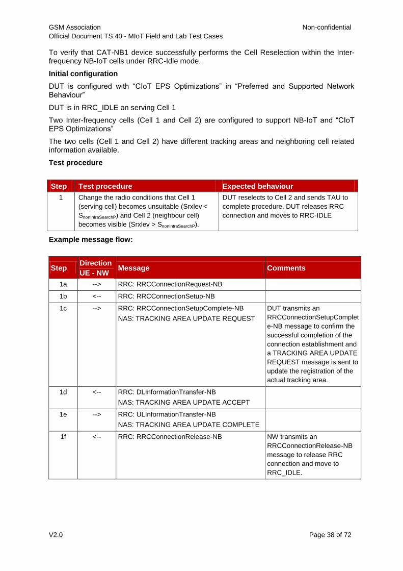
Example message flow:
Step Direction
UE - NW Message Comments
1a --> RRC: RRCConnectionRequest-NB
1b <-- RRC: RRCConnectionSetup-NB
1c --> RRC: RRCConnectionSetupComplete-NB
NAS: TRACKING AREA UPDATE REQUEST
DUT transmits an
RRCConnectionSetupComplet
e-NB message to confirm the
successful completion of the
connection establishment and
a TRACKING AREA UPDATE
REQUEST message is sent to
update the registration of the
actual tracking area.
1d <-- RRC: DLInformationTransfer-NB
NAS: TRACKING AREA UPDATE ACCEPT
1e --> RRC: ULInformationTransfer-NB
NAS: TRACKING AREA UPDATE COMPLETE
1f <-- RRC: RRCConnectionRelease-NB NW transmits an
RRCConnectionRelease-NB
message to release RRC
connection and move to
RRC_IDLE.
2.4.1.3 CAT-NB1 Device Inter-Frequency Cell Reselection
Description
To verify that CAT-NB1 device successfully performs the Cell Reselection within the Inter-frequency NB-IoT cells under RRC-Idle mode.
Related core specifications
GSMA TS.39_2.5.1_REQ_001 (Cell Reselection)
3GPP TS 36.304, TS 36.300, and TS 36.331
Reason for test
GSM Association Non-confidential
Official Document TS.40 - MIoT Field and Lab Test Cases
V2.0 Page 38 of 72
To verify that CAT-NB1 device successfully performs the Cell Reselection within the Inter-frequency NB-IoT cells under RRC-Idle mode.
Initial configuration
DUT is configured with “CIoT EPS Optimizations” in “Preferred and Supported Network Behaviour”
DUT is in RRC_IDLE on serving Cell 1
Two Inter-frequency cells (Cell 1 and Cell 2) are configured to support NB-IoT and “CIoT EPS Optimizations”
The two cells (Cell 1 and Cell 2) have different tracking areas and neighboring cell related information available.
Test procedure
Step Test procedure Expected behaviour
1 Change the radio conditions that Cell 1
(serving cell) becomes unsuitable (Srxlev <
SnonIntraSearchP) and Cell 2 (neighbour cell)
becomes visible (Srxlev > SnonIntraSearchP).
DUT reselects to Cell 2 and sends TAU to
complete procedure. DUT releases RRC
connection and moves to RRC-IDLE
Example message flow:
Step Direction
UE - NW Message Comments
1a --> RRC: RRCConnectionRequest-NB
1b <-- RRC: RRCConnectionSetup-NB
1c --> RRC: RRCConnectionSetupComplete-NB
NAS: TRACKING AREA UPDATE REQUEST
DUT transmits an
RRCConnectionSetupComplet
e-NB message to confirm the
successful completion of the
connection establishment and
a TRACKING AREA UPDATE
REQUEST message is sent to
update the registration of the
actual tracking area.
1d <-- RRC: DLInformationTransfer-NB
NAS: TRACKING AREA UPDATE ACCEPT
1e --> RRC: ULInformationTransfer-NB
NAS: TRACKING AREA UPDATE COMPLETE
1f <-- RRC: RRCConnectionRelease-NB NW transmits an
RRCConnectionRelease-NB
message to release RRC
connection and move to
RRC_IDLE.
GSM Association Non-confidential
Official Document TS.40 - MIoT Field and Lab Test Cases
V2.0 Page 39 of 72
2.4.2 Connected Mode Mobility
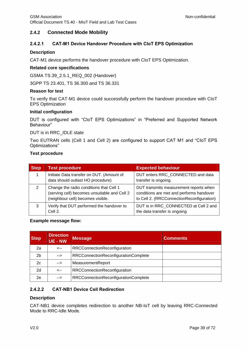
2.4.2.1 CAT-M1 Device Handover Procedure with CIoT EPS Optimization
Description
CAT-M1 device performs the handover procedure with CIoT EPS Optimization.
Related core specifications
GSMA TS.39_2.5.1_REQ_002 (Handover)
3GPP TS 23.401, TS 36.300 and TS 36.331
Reason for test
To verify that CAT-M1 device could successfully perform the handover procedure with CIoT EPS Optimization
Initial configuration
DUT is configured with “CIoT EPS Optimizations” in “Preferred and Supported Network Behaviour”
DUT is in RRC_IDLE state
Two EUTRAN cells (Cell 1 and Cell 2) are configured to support CAT M1 and “CIoT EPS Optimizations”
Test procedure
Step Test procedure Expected behaviour
1 Initiate Data transfer on DUT. (Amount of
data should outlast HO procedure)
DUT enters RRC_CONNECTED and data
transfer is ongoing.
2 Change the radio conditions that Cell 1
(serving cell) becomes unsuitable and Cell 2
(neighbour cell) becomes visible.
DUT transmits measurement reports when
conditions are met and performs handover
to Cell 2. (RRCConnectionReconfiguration)
3 Verify that DUT performed the handover to
Cell 2.
DUT is in RRC_CONNECTED at Cell 2 and
the data transfer is ongoing
Example message flow:
Step Direction
UE - NW Message Comments
2a <-- RRCConnectionReconfiguration
2b --> RRCConnectionReconfigurationComplete
2c --> MeasurementReport
2d <-- RRCConnectionReconfiguration
2e --> RRCConnectionReconfigurationComplete
2.4.2.2 CAT-NB1 Device Cell Redirection
Description
CAT-NB1 device completes redirection to another NB-IoT cell by leaving RRC-Connected Mode to RRC-Idle Mode.
GSM Association Non-confidential
Official Document TS.40 - MIoT Field and Lab Test Cases
V2.0 Page 40 of 72
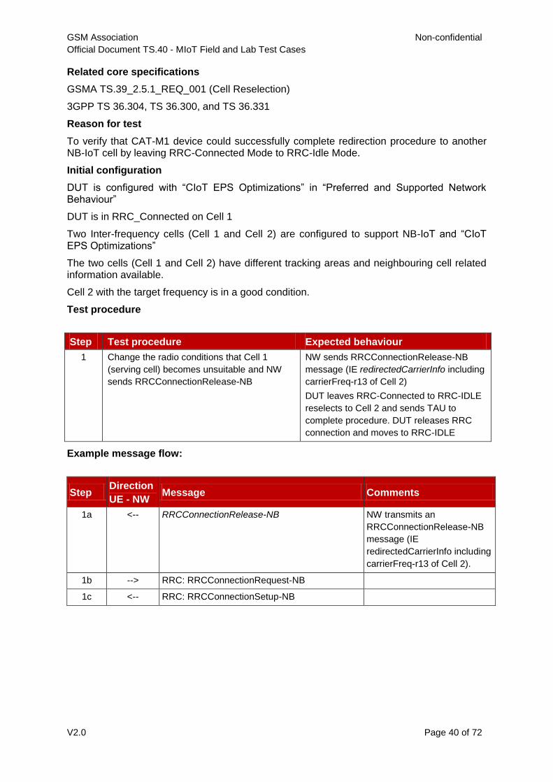
Related core specifications
GSMA TS.39_2.5.1_REQ_001 (Cell Reselection)
3GPP TS 36.304, TS 36.300, and TS 36.331
Reason for test
To verify that CAT-M1 device could successfully complete redirection procedure to another NB-IoT cell by leaving RRC-Connected Mode to RRC-Idle Mode.
Initial configuration
DUT is configured with “CIoT EPS Optimizations” in “Preferred and Supported Network Behaviour”
DUT is in RRC_Connected on Cell 1
Two Inter-frequency cells (Cell 1 and Cell 2) are configured to support NB-IoT and “CIoT EPS Optimizations”
The two cells (Cell 1 and Cell 2) have different tracking areas and neighbouring cell related information available.
Cell 2 with the target frequency is in a good condition.
Test procedure
Step Test procedure Expected behaviour
1 Change the radio conditions that Cell 1
(serving cell) becomes unsuitable and NW
sends RRCConnectionRelease-NB
NW sends RRCConnectionRelease-NB
message (IE redirectedCarrierInfo including
carrierFreq-r13 of Cell 2)
DUT leaves RRC-Connected to RRC-IDLE
reselects to Cell 2 and sends TAU to
complete procedure. DUT releases RRC
connection and moves to RRC-IDLE
Example message flow:
Step Direction
UE - NW Message Comments
1a <-- RRCConnectionRelease-NB NW transmits an
RRCConnectionRelease-NB
message (IE
redirectedCarrierInfo including
carrierFreq-r13 of Cell 2).
1b --> RRC: RRCConnectionRequest-NB
1c <-- RRC: RRCConnectionSetup-NB

GSM Association Non-confidential
Official Document TS.40 - MIoT Field and Lab Test Cases
V2.0 Page 41 of 72
Step Direction
UE - NW Message Comments
1d --> RRC: RRCConnectionSetupComplete-NB
NAS: TRACKING AREA UPDATE REQUEST
DUT transmits an
RRCConnectionSetupComplet
e-NB message to confirm the
successful completion of the
connection establishment and
a TRACKING AREA UPDATE
REQUEST message is sent to
update the registration of the
actual tracking area.
1e <-- RRC: DLInformationTransfer-NB
NAS: TRACKING AREA UPDATE ACCEPT
1f --> RRC: ULInformationTransfer-NB
NAS: TRACKING AREA UPDATE COMPLETE
1g <-- RRC: RRCConnectionRelease-NB NW transmits an
RRCConnectionRelease-NB
message to release RRC
connection and move to
RRC_IDLE.
2.5 Device Capabilities
2.5.1 CAT-NB1 Uplink Transmission Capability – 3.7kHz (Single-tone)
Description
For CAT-NB1 device, uplink transmission capability (3.75kHz, single-tone) needs to be verified.
Related core specifications
3GPP TS 36.211, TS 36.331.
Reason for test
Verify CAT-NB1 device can support single-tone transmission with 3.75kHz subcarrier spacing.
Initial configuration
NB-IoT eNodeB is configured to only support single-tone transmission with 3.75kHz subcarrier spacing.
This test requires logging tools.
Test procedure
Step Test procedure Expected behaviour
1 Powers on DUT DUT successfully access the cell
2 Perform uplink data transfer Using logging tool to verify DCI Format N0
indicate 3.75kHz/single-tone.
Uplink data is successfully transferred
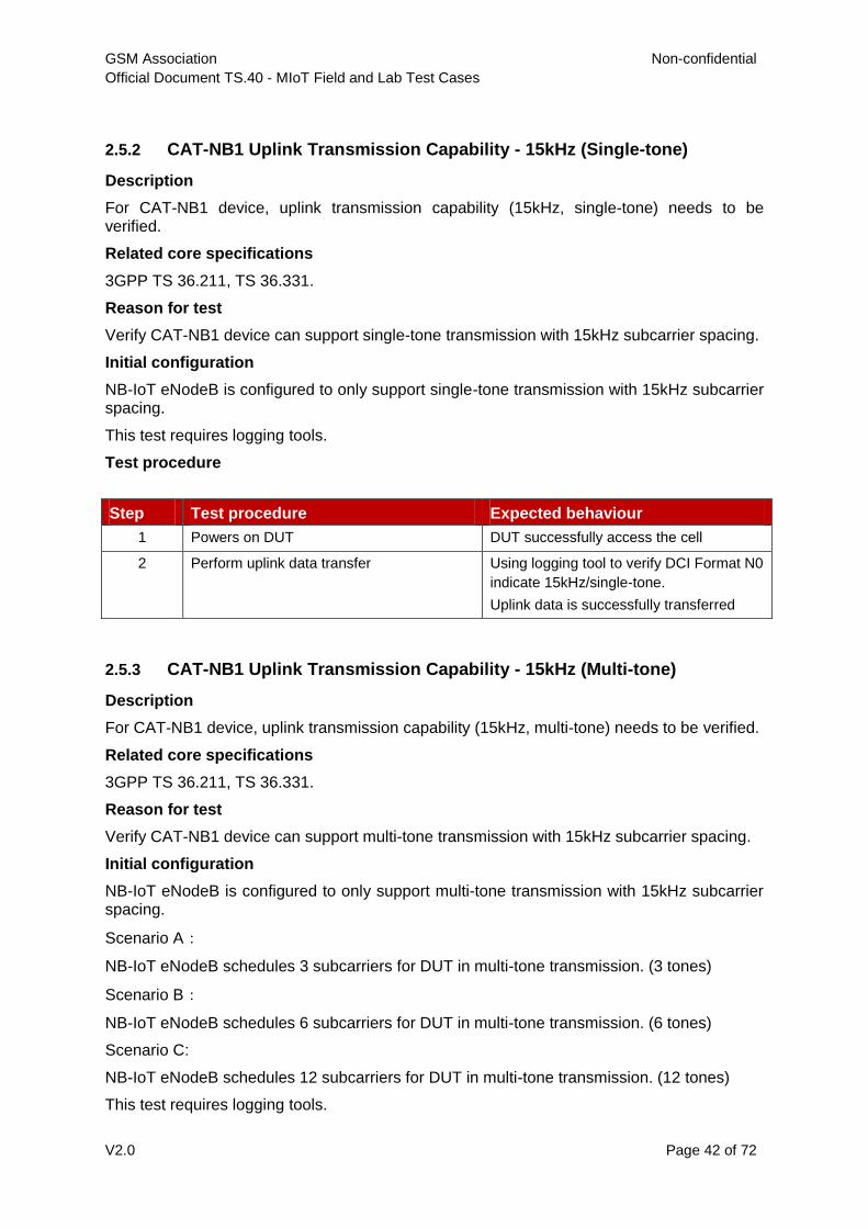
GSM Association Non-confidential
Official Document TS.40 - MIoT Field and Lab Test Cases
V2.0 Page 42 of 72
2.5.2 CAT-NB1 Uplink Transmission Capability - 15kHz (Single-tone)
Description
For CAT-NB1 device, uplink transmission capability (15kHz, single-tone) needs to be verified.
Related core specifications
3GPP TS 36.211, TS 36.331.
Reason for test
Verify CAT-NB1 device can support single-tone transmission with 15kHz subcarrier spacing.
Initial configuration
NB-IoT eNodeB is configured to only support single-tone transmission with 15kHz subcarrier spacing.
This test requires logging tools.
Test procedure
Step Test procedure Expected behaviour
1 Powers on DUT DUT successfully access the cell
2 Perform uplink data transfer Using logging tool to verify DCI Format N0
indicate 15kHz/single-tone.
Uplink data is successfully transferred
2.5.3 CAT-NB1 Uplink Transmission Capability - 15kHz (Multi-tone)
Description
For CAT-NB1 device, uplink transmission capability (15kHz, multi-tone) needs to be verified.
Related core specifications
3GPP TS 36.211, TS 36.331.
Reason for test
Verify CAT-NB1 device can support multi-tone transmission with 15kHz subcarrier spacing.
Initial configuration
NB-IoT eNodeB is configured to only support multi-tone transmission with 15kHz subcarrier spacing.
Scenario A:
NB-IoT eNodeB schedules 3 subcarriers for DUT in multi-tone transmission. (3 tones)
Scenario B:
NB-IoT eNodeB schedules 6 subcarriers for DUT in multi-tone transmission. (6 tones)
Scenario C:
NB-IoT eNodeB schedules 12 subcarriers for DUT in multi-tone transmission. (12 tones)
This test requires logging tools.
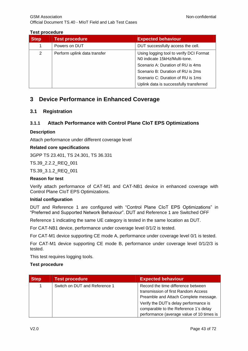
GSM Association Non-confidential
Official Document TS.40 - MIoT Field and Lab Test Cases
V2.0 Page 43 of 72
Test procedure
Step Test procedure Expected behaviour
1 Powers on DUT DUT successfully access the cell.
2 Perform uplink data transfer Using logging tool to verify DCI Format
N0 indicate 15kHz/Multi-tone.
Scenario A: Duration of RU is 4ms
Scenario B: Duration of RU is 2ms
Scenario C: Duration of RU is 1ms
Uplink data is successfully transferred
3 Device Performance in Enhanced Coverage
3.1 Registration
3.1.1 Attach Performance with Control Plane CIoT EPS Optimizations
Description
Attach performance under different coverage level
Related core specifications
3GPP TS 23.401, TS 24.301, TS 36.331
TS.39_2.2.2_REQ_001
TS.39_3.1.2_REQ_001
Reason for test
Verify attach performance of CAT-M1 and CAT-NB1 device in enhanced coverage with Control Plane CIoT EPS Optimizations.
Initial configuration
DUT and Reference 1 are configured with “Control Plane CIoT EPS Optimizations” in “Preferred and Supported Network Behaviour”. DUT and Reference 1 are Switched OFF
Reference 1 indicating the same UE category is tested in the same location as DUT.
For CAT-NB1 device, performance under coverage level 0/1/2 is tested.
For CAT-M1 device supporting CE mode A, performance under coverage level 0/1 is tested.
For CAT-M1 device supporting CE mode B, performance under coverage level 0/1/2/3 is tested.
This test requires logging tools.
Test procedure
Step Test procedure Expected behaviour
1 Switch on DUT and Reference 1 Record the time difference between
transmission of first Random Access
Preamble and Attach Complete message.
Verify the DUT’s delay performance is
comparable to the Reference 1’s delay
performance (average value of 10 times is
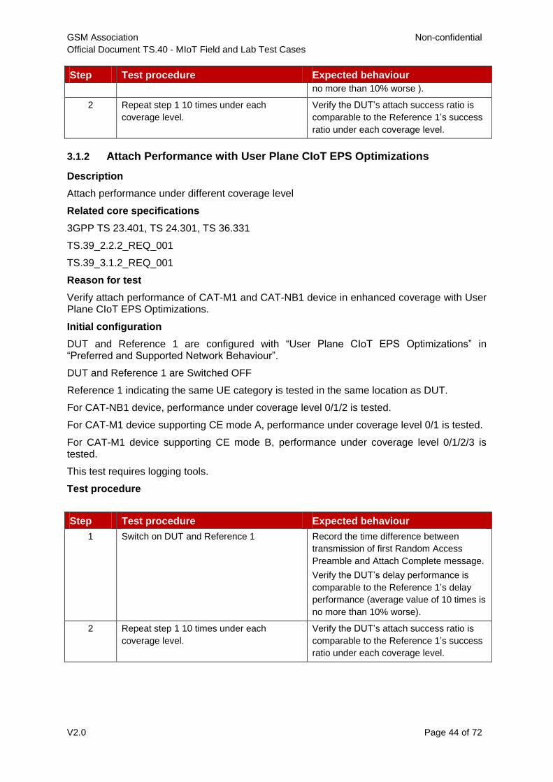
GSM Association Non-confidential
Official Document TS.40 - MIoT Field and Lab Test Cases
V2.0 Page 44 of 72
Step Test procedure Expected behaviour
no more than 10% worse ).
2 Repeat step 1 10 times under each
coverage level.
Verify the DUT’s attach success ratio is
comparable to the Reference 1’s success
ratio under each coverage level.
3.1.2 Attach Performance with User Plane CIoT EPS Optimizations
Description
Attach performance under different coverage level
Related core specifications
3GPP TS 23.401, TS 24.301, TS 36.331
TS.39_2.2.2_REQ_001
TS.39_3.1.2_REQ_001
Reason for test
Verify attach performance of CAT-M1 and CAT-NB1 device in enhanced coverage with User Plane CIoT EPS Optimizations.
Initial configuration
DUT and Reference 1 are configured with “User Plane CIoT EPS Optimizations” in “Preferred and Supported Network Behaviour”.
DUT and Reference 1 are Switched OFF
Reference 1 indicating the same UE category is tested in the same location as DUT.
For CAT-NB1 device, performance under coverage level 0/1/2 is tested.
For CAT-M1 device supporting CE mode A, performance under coverage level 0/1 is tested.
For CAT-M1 device supporting CE mode B, performance under coverage level 0/1/2/3 is tested.
This test requires logging tools.
Test procedure
Step Test procedure Expected behaviour
1 Switch on DUT and Reference 1 Record the time difference between
transmission of first Random Access
Preamble and Attach Complete message.
Verify the DUT’s delay performance is
comparable to the Reference 1’s delay
performance (average value of 10 times is
no more than 10% worse).
2 Repeat step 1 10 times under each
coverage level.
Verify the DUT’s attach success ratio is
comparable to the Reference 1’s success
ratio under each coverage level.

GSM Association Non-confidential
Official Document TS.40 - MIoT Field and Lab Test Cases
V2.0 Page 45 of 72
3.2 Paging
3.2.1 Paging performance under different coverage level
Description
Paging performance under different coverage level
Related core specifications
3GPP TS 36.331
Reason for test
Verify paging performance of CAT-M1 and CAT-NB1 device under different coverage level.
Initial configuration
The NW supports the paging procedure when downlink data request is generated.
Reference 1 indicating the same UE category is tested in the same location as DUT. For Cat-NB1 device, performance under coverage level 0/1/2 is tested.
For CAT-M1 device supporting CE mode A, performance under coverage level 0/1 is tested.
For CAT-M1 device supporting CE mode B, performance under coverage level 0/1/2/3 is tested.
eDRX is disabled on DUT and Reference 1.
DUT and Reference 1 are in RRC_IDLE.
This test requires logging tools.
Test procedure
Step Test procedure Expected behaviour
1 Downlink data request is sent to DUT
and Reference 1
None
2 Verify the DUT successfully establishes
RRC Connection.
Record the time difference between
reception of paging message and
transmission of
RRCConnetctionSetupComplete
message.
Verify the DUT’s delay performance is
comparable to the Reference 1’s delay
performance (no more than 10% worse).
3 Repeat step 1-2 10 times under each
coverage level.
Verify the DUT’s paging success ratio is
comparable to the Reference 1’s success
ratio under each coverage level
3.2.2 Paging with eDRX cycle under different coverage level
Description
Performance of paging with eDRX cycle under different coverage level
Related core specifications
3GPP TS 36.331
Reason for test

GSM Association Non-confidential
Official Document TS.40 - MIoT Field and Lab Test Cases
V2.0 Page 46 of 72
Verify paging performance of CAT-M1 and CAT-NB1 device under different coverage level when eDRX cycle is configured.
Initial configuration
The NW supports the paging procedure when downlink data request is generated.
Reference 1 indicating the same UE category is tested in the same location as DUT.
For CAT-NB1 device, performance under coverage level 0/1/2 is tested.
For CAT-M1 device supporting CE mode A, performance under coverage level 0/1 is tested.
For CAT-M1 device supporting CE mode B, performance under coverage level 0/1/2/3 is tested.
eDRX is enabled on DUT and Reference 1 with similar configuration.
DUT and Reference 1 are in RRC_IDLE.
This test requires logging tools.
Test procedure
Step Test procedure Expected behaviour
1 Downlink data request is sent to DUT and Reference 1
Extended DRX parameters is included in downlink data request.
2 Verify the DUT and Reference 1 successfully establishes RRC Connection
DUT’s and Reference 1 are in RRC-Connected mode.
3 Repeat step 1-2 10 times under each coverage level.
Verify the DUT’s paging success ratio is comparable to the Reference 1’s success ratio under each coverage level
3.3 Data Transfer and Throughput
3.3.1 Data Transfer and Throughput with Control Plane CIoT EPS
Optimizations - IP PDN Type
Description
Data transfer performance via IP
Related core specifications
3GPP TS 23.401, TS 24.301, TS 36.211, TS 36.213
TS.39_3.2.2_REQ_001, TS.39_3.2.2_REQ_003
Reason for test
Verify data transfer performance of CAT-M1 and CAT-NB1 device use IP PDN Type with Control Plane CIoT EPS Optimizations.
Initial configuration
DUT is configured with “Control Plane CIoT EPS Optimizations” in “Preferred and Supported Network Behaviour”.
DUT is configured to support IP PDN Type
DUT is in RRC_CONNECTED State.
Reference 1 indicating the same UE category is tested in the same location as DUT.

GSM Association Non-confidential
Official Document TS.40 - MIoT Field and Lab Test Cases
V2.0 Page 47 of 72
For CAT-NB1 device, performance under coverage level 0/1/2 is tested.
For CAT-M1 device supporting CE mode A, performance under coverage level 0/1 is tested.
For CAT-M1 device supporting CE mode B, performance under coverage level 0/1/2/3 is tested.
Test procedure
Step Test procedure Expected behaviour
1 Perform uplink data transfer on DUT and
Reference 1 for 60s
Verify the DUT’s uplink data throughput is
comparable to the Reference 1’s
throughput (no more than 10% worse).
2 Perform downlink data transfer on DUT and
Reference 1 for 60s
Verify the DUT’s downlink data throughput
is comparable to the Reference 1’s
throughput (no more than 10% worse).
3 Repeat step 1-2 10 times under each
coverage level.
Verify the DUT has comparable data
performance to the Reference 1 under
each coverage level
3.3.2 Data Transfer and Throughput with Control Plane CIoT EPS
Optimizations - Non IP PDN Type
Description
Data transfer performance via non-IP
Related core specifications
3GPP TS 23.401, TS 24.301, TS 36.211, TS 36.213
TS.39_3.2.2_REQ_001, TS.39_3.2.2_REQ_003
Reason for test
Verify data transfer performance of CAT-M1 and CAT-NB1 device use Non IP PDN Type with Control Plane CIoT EPS Optimizations.
Initial configuration
DUT is configured with “Control Plane CIoT EPS Optimizations” in “Preferred and Supported Network Behaviour”.
DUT is configured to support Non IP PDN Type
DUT is in RRC_CONNECTED State.
Reference 1 indicating the same UE category is tested in the same location as DUT.
For CAT-NB1 device, performance under coverage level 0/1/2 is tested.
For CAT-M1 device supporting CE mode A, performance under coverage level 0/1 is tested.
For CAT-M1 device supporting CE mode B, performance under coverage level 0/1/2/3 is tested.
Test procedure
Step Test procedure Expected behaviour
1 Perform uplink data transfer on DUT and Verify the DUT’s uplink data throughput is
comparable to the Reference 1’s
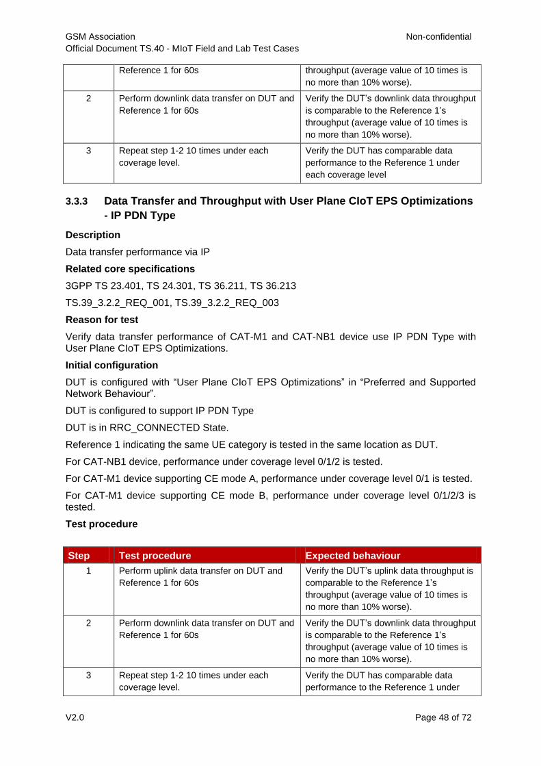
GSM Association Non-confidential
Official Document TS.40 - MIoT Field and Lab Test Cases
V2.0 Page 48 of 72
Reference 1 for 60s throughput (average value of 10 times is
no more than 10% worse).
2 Perform downlink data transfer on DUT and
Reference 1 for 60s
Verify the DUT’s downlink data throughput
is comparable to the Reference 1’s
throughput (average value of 10 times is
no more than 10% worse).
3 Repeat step 1-2 10 times under each
coverage level.
Verify the DUT has comparable data
performance to the Reference 1 under
each coverage level
3.3.3 Data Transfer and Throughput with User Plane CIoT EPS Optimizations
- IP PDN Type
Description
Data transfer performance via IP
Related core specifications
3GPP TS 23.401, TS 24.301, TS 36.211, TS 36.213
TS.39_3.2.2_REQ_001, TS.39_3.2.2_REQ_003
Reason for test
Verify data transfer performance of CAT-M1 and CAT-NB1 device use IP PDN Type with User Plane CIoT EPS Optimizations.
Initial configuration
DUT is configured with “User Plane CIoT EPS Optimizations” in “Preferred and Supported Network Behaviour”.
DUT is configured to support IP PDN Type
DUT is in RRC_CONNECTED State.
Reference 1 indicating the same UE category is tested in the same location as DUT.
For CAT-NB1 device, performance under coverage level 0/1/2 is tested.
For CAT-M1 device supporting CE mode A, performance under coverage level 0/1 is tested.
For CAT-M1 device supporting CE mode B, performance under coverage level 0/1/2/3 is tested.
Test procedure
Step Test procedure Expected behaviour
1 Perform uplink data transfer on DUT and
Reference 1 for 60s
Verify the DUT’s uplink data throughput is
comparable to the Reference 1’s
throughput (average value of 10 times is
no more than 10% worse).
2 Perform downlink data transfer on DUT and
Reference 1 for 60s
Verify the DUT’s downlink data throughput
is comparable to the Reference 1’s
throughput (average value of 10 times is
no more than 10% worse).
3 Repeat step 1-2 10 times under each
coverage level.
Verify the DUT has comparable data
performance to the Reference 1 under
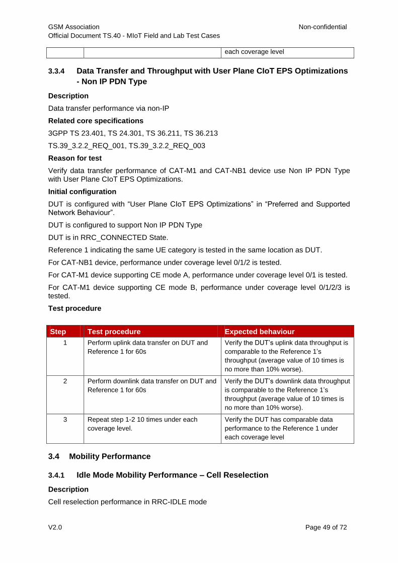
GSM Association Non-confidential
Official Document TS.40 - MIoT Field and Lab Test Cases
V2.0 Page 49 of 72
each coverage level
3.3.4 Data Transfer and Throughput with User Plane CIoT EPS Optimizations
- Non IP PDN Type
Description
Data transfer performance via non-IP
Related core specifications
3GPP TS 23.401, TS 24.301, TS 36.211, TS 36.213
TS.39_3.2.2_REQ_001, TS.39_3.2.2_REQ_003
Reason for test
Verify data transfer performance of CAT-M1 and CAT-NB1 device use Non IP PDN Type with User Plane CIoT EPS Optimizations.
Initial configuration
DUT is configured with “User Plane CIoT EPS Optimizations” in “Preferred and Supported Network Behaviour”.
DUT is configured to support Non IP PDN Type
DUT is in RRC_CONNECTED State.
Reference 1 indicating the same UE category is tested in the same location as DUT.
For CAT-NB1 device, performance under coverage level 0/1/2 is tested.
For CAT-M1 device supporting CE mode A, performance under coverage level 0/1 is tested.
For CAT-M1 device supporting CE mode B, performance under coverage level 0/1/2/3 is tested.
Test procedure
Step Test procedure Expected behaviour
1 Perform uplink data transfer on DUT and
Reference 1 for 60s
Verify the DUT’s uplink data throughput is
comparable to the Reference 1’s
throughput (average value of 10 times is
no more than 10% worse).
2 Perform downlink data transfer on DUT and
Reference 1 for 60s
Verify the DUT’s downlink data throughput
is comparable to the Reference 1’s
throughput (average value of 10 times is
no more than 10% worse).
3 Repeat step 1-2 10 times under each
coverage level.
Verify the DUT has comparable data
performance to the Reference 1 under
each coverage level
3.4 Mobility Performance
3.4.1 Idle Mode Mobility Performance – Cell Reselection
Description
Cell reselection performance in RRC-IDLE mode

GSM Association Non-confidential
Official Document TS.40 - MIoT Field and Lab Test Cases
V2.0 Page 50 of 72
Related core specifications
GSMA TS.39_2.5.1_REQ_001
3GPP TS 36.300, TS 36.304, TS 36.331
Reason for test
To verify cell reselection performance of CAT-M1 and CAT-NB1 device under RRC-IDLE mode in mobility state.
Initial configuration
A number of cells(NB-IoT/ E-UTRAN) is available along the test route.
Reference 1 indicates the same UE category as DUT.
DUT and Reference 1 are moving in the same test route at the same speed.
DUT and Reference 1 are in RRC_IDLE.
This test requires logging tools.
Test procedure
Step Test procedure Expected behaviour
1 Drive along the test route, Verify the DUT’s cell reselection success
ratio is comparable to the Reference 1’s cell
reselection success ratio. (no more than
10% worse).
3.4.2 Connected Mode Mobility Performance
3.4.2.1 Cat-M1 Device Connected Mode Mobility Performance - Handover
Description
Handover performance of CAT-M1 device
Related core specifications
GSMA TS.39_2.5.1_REQ_002
3GPP TS 36.300, TS 36.331
Reason for test
To verify handover performance of CAT-M1 device under RRC-CONNECTED mode in mobility state.
Initial configuration
A number of E-UTRAN cells is available along the test route.
Reference 1 indicates the same UE category as DUT.
DUT and Reference 1 are moving in the same test route at the same speed.
DUT and Reference 1 are in RRC_CONNECTED state.
This test requires logging tools.
Test procedure
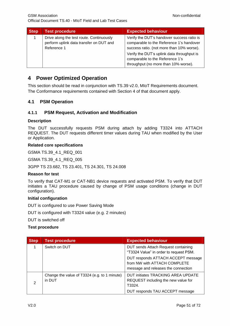
GSM Association Non-confidential
Official Document TS.40 - MIoT Field and Lab Test Cases
V2.0 Page 51 of 72
Step Test procedure Expected behaviour
1 Drive along the test route. Continuously
perform uplink data transfer on DUT and
Reference 1
Verify the DUT’s handover success ratio is
comparable to the Reference 1’s handover
success ratio. (not more than 10% worse).
Verify the DUT’s uplink data throughput is
comparable to the Reference 1’s
throughput (no more than 10% worse).
4 Power Optimized Operation
This section should be read in conjunction with TS.39 v2.0, MIoT Requirements document.
The Conformance requirements contained with Section 4 of that document apply.
4.1 PSM Operation
4.1.1 PSM Request, Activation and Modification
Description
The DUT successfully requests PSM during attach by adding T3324 into ATTACH REQUEST. The DUT requests different timer values during TAU when modified by the User or Application.
Related core specifications
GSMA TS.39_4.1_REQ_001
GSMA TS.39_4.1_REQ_005
3GPP TS 23.682, TS 23.401, TS 24.301, TS 24.008
Reason for test
To verify that CAT-M1 or CAT-NB1 device requests and activated PSM. To verify that DUT initiates a TAU procedure caused by change of PSM usage conditions (change in DUT configuration).
Initial configuration
DUT is configured to use Power Saving Mode
DUT is configured with T3324 value (e.g. 2 minutes)
DUT is switched off
Test procedure
Step Test procedure Expected behaviour
1 Switch on DUT DUT sends Attach Request containing
“T3324 Value” in order to request PSM.
DUT responds ATTACH ACCEPT message
from NW with ATTACH COMPLETE
message and releases the connection
2
Change the value of T3324 (e.g. to 1 minute)
in DUT
DUT initiates TRACKING AREA UPDATE
REQUEST including the new value for
T3324.
DUT responds TAU ACCEPT message
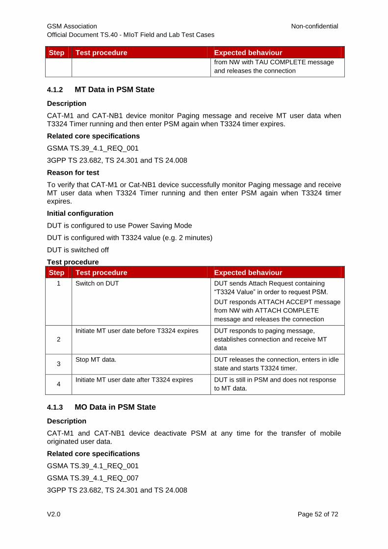
GSM Association Non-confidential
Official Document TS.40 - MIoT Field and Lab Test Cases
V2.0 Page 52 of 72
Step Test procedure Expected behaviour
from NW with TAU COMPLETE message
and releases the connection
4.1.2 MT Data in PSM State
Description
CAT-M1 and CAT-NB1 device monitor Paging message and receive MT user data when T3324 Timer running and then enter PSM again when T3324 timer expires.
Related core specifications
GSMA TS.39_4.1_REQ_001
3GPP TS 23.682, TS 24.301 and TS 24.008
Reason for test
To verify that CAT-M1 or Cat-NB1 device successfully monitor Paging message and receive MT user data when T3324 Timer running and then enter PSM again when T3324 timer expires.
Initial configuration
DUT is configured to use Power Saving Mode
DUT is configured with T3324 value (e.g. 2 minutes)
DUT is switched off
Test procedure
Step Test procedure Expected behaviour
1 Switch on DUT DUT sends Attach Request containing
“T3324 Value” in order to request PSM.
DUT responds ATTACH ACCEPT message
from NW with ATTACH COMPLETE
message and releases the connection
2
Initiate MT user date before T3324 expires DUT responds to paging message,
establishes connection and receive MT
data
3 Stop MT data. DUT releases the connection, enters in idle
state and starts T3324 timer.
4 Initiate MT user date after T3324 expires DUT is still in PSM and does not response
to MT data.
4.1.3 MO Data in PSM State
Description
CAT-M1 and CAT-NB1 device deactivate PSM at any time for the transfer of mobile originated user data.
Related core specifications
GSMA TS.39_4.1_REQ_001
GSMA TS.39_4.1_REQ_007
3GPP TS 23.682, TS 24.301 and TS 24.008

GSM Association Non-confidential
Official Document TS.40 - MIoT Field and Lab Test Cases
V2.0 Page 53 of 72
Reason for test
To verify that CAT-M1 or CAT-NB1 device successfully deactivate PSM at any time for the transfer of mobile originated user data.
Initial configuration
DUT is configured to use Power Saving Mode
DUT is configured with T3324 value (e.g. 2 minutes)
DUT is switched off
Test procedure
Step Test procedure Expected behaviour
1 Switch on DUT DUT sends Attach Request containing
“T3324 Value” in order to request PSM.
DUT responds ATTACH ACCEPT message
from NW with ATTACH COMPLETE
message and releases the connection
2 Wait until T3324 expires DUT enters PSM after T3324 expires
3 Attempt to page DUT to verify PSM state DUT is in PSM and does not response to
MT data.
4 Initiate MO user date DUT shall deactivate PSM , establish
connection and send MO data
4.1.4 Periodic Tracking Area Update
Description
CAT-M1 and CAT-NB1 device performs a Periodic Tracking Area Update procedure after the expiry of the T3412/T3312 timer when PSM is activated.
Related core specifications
GSMA TS.39_4.1_REQ_001
3GPP TS 23.682, TS 24.301 and TS 24.008
Reason for test
To verify that CAT-M1 or CAT-NB1 device successfully performs a Periodic Tracking Area Update procedure after the expiry of the T3412/T3312 timer when PSM is activated.
Initial configuration
DUT is configured to use Power Saving Mode
DUT is configured with T3324 value (e.g.2 minutes)
DUT is switched off
Test procedure
Step Test procedure Expected behaviour
1 Switch on DUT DUT sends Attach Request containing
“T3324 Value” in order to request PSM.
NW sends ATTACH ACCEPT message
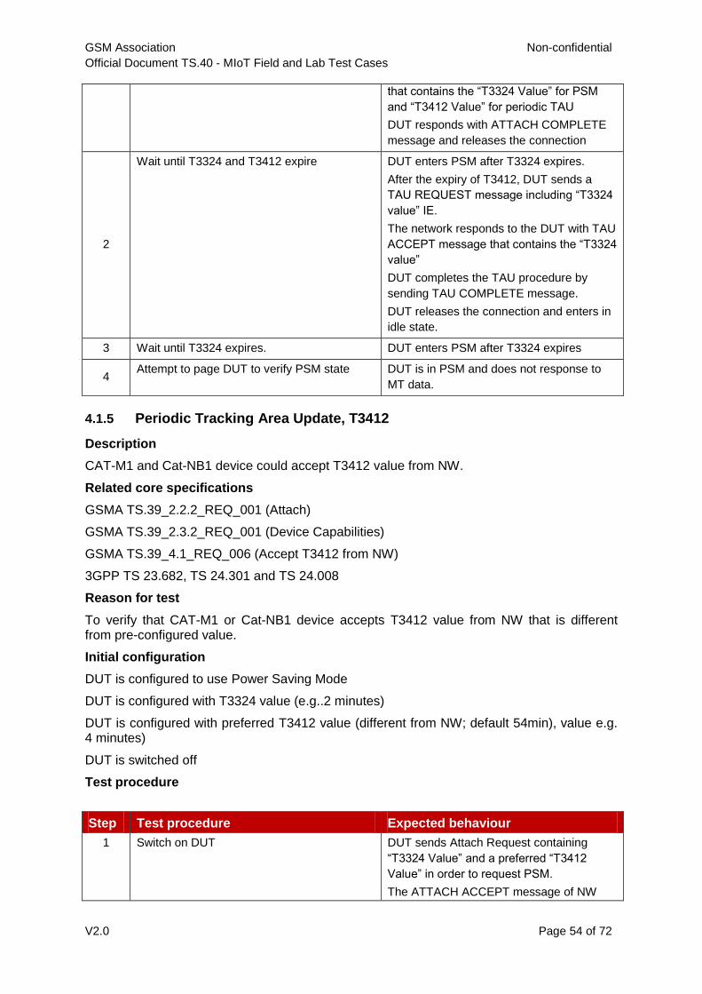
GSM Association Non-confidential
Official Document TS.40 - MIoT Field and Lab Test Cases
V2.0 Page 54 of 72
that contains the “T3324 Value” for PSM
and “T3412 Value” for periodic TAU
DUT responds with ATTACH COMPLETE
message and releases the connection
2
Wait until T3324 and T3412 expire DUT enters PSM after T3324 expires.
After the expiry of T3412, DUT sends a
TAU REQUEST message including “T3324
value” IE.
The network responds to the DUT with TAU
ACCEPT message that contains the “T3324
value”
DUT completes the TAU procedure by
sending TAU COMPLETE message.
DUT releases the connection and enters in
idle state.
3 Wait until T3324 expires. DUT enters PSM after T3324 expires
4 Attempt to page DUT to verify PSM state DUT is in PSM and does not response to
MT data.
4.1.5 Periodic Tracking Area Update, T3412
Description
CAT-M1 and Cat-NB1 device could accept T3412 value from NW.
Related core specifications
GSMA TS.39_2.2.2_REQ_001 (Attach)
GSMA TS.39_2.3.2_REQ_001 (Device Capabilities)
GSMA TS.39_4.1_REQ_006 (Accept T3412 from NW)
3GPP TS 23.682, TS 24.301 and TS 24.008
Reason for test
To verify that CAT-M1 or Cat-NB1 device accepts T3412 value from NW that is different from pre-configured value.
Initial configuration
DUT is configured to use Power Saving Mode
DUT is configured with T3324 value (e.g..2 minutes)
DUT is configured with preferred T3412 value (different from NW; default 54min), value e.g. 4 minutes)
DUT is switched off
Test procedure
Step Test procedure Expected behaviour
1 Switch on DUT DUT sends Attach Request containing
“T3324 Value” and a preferred “T3412
Value” in order to request PSM.
The ATTACH ACCEPT message of NW

GSM Association Non-confidential
Official Document TS.40 - MIoT Field and Lab Test Cases
V2.0 Page 55 of 72
contains different T3412 value.
DUT accepts new value for T3412 in
ATTACH COMPLETE MESSAGE
2 Wait until DUT is in IDLE and T3324 expires DUT enters PSM after T3324 expires
3 Wait until T3412 expires and verify that the
DUT initiates Tracking Area update.
DUT initiates TAU after expiry of T3412
(NW value)
4.1.6 Reduced Current Drain in PSM
Description
CAT-M1 and CAT-NB1 device support a reduced current drain when in Power Saving Mode.
Related core specifications
GSMA TS.39_4.1_REQ_003
3GPP TS 23.682, TS 24.301 and TS 24.008
Reason for test
To verify that CAT-M1 or CAT-NB1 device support a reduced current drain when in PSM.
Initial configuration
DUT is configured to disable Power Saving Mode
DUT is configured with T3324 value (e.g. 2 minutes)
DUT battery is replaced with “dummy battery” that is connected to a combined DC power source and current measurement device.
DUT is switched off
All other radios (e.g. Wi-Fi, BT, etc.) in DUT are switched off
Test procedure
Step Test procedure Expected behaviour
1 Switch on DUT DUT registers to the NW
2 Wait 3 min after DUT has completed
registration.
DUT is registered and in IDLE mode
3
Record a minimum of 120 samples over a
continuous 30 minute period, using
ammeters or automated power monitors if
available.
‘-
4
Calculate the average current drain from
the measured samples, denoted by
IPSM_Disabled.
‘-
5
Configure the DUT to use PSM with timer
T3412 set to at least 30 minutes. Switch off
the DUT.
‘-
6
Switch on DUT and wait 3 minutes after
DUT has completed registration
DUT sends ATTACH REQUEST
containing “T3324 Value” in order to
request PSM.
7 In PSM mode, record a minimum of 120 ‘-

GSM Association Non-confidential
Official Document TS.40 - MIoT Field and Lab Test Cases
V2.0 Page 56 of 72
samples over a continuous 30 minute
period, using ammeters or automated
power monitors if available
8
Calculate the average current drain from
the measured samples, denoted by
IPSM_Enabled
The current drain in PSM (IPSM_Enabled)
should be several orders of magnitude
lower than the one in idle mode
(IPSM_Disabled)
4.1.7 Periodic Tracking Area Update Power Consumption Performance
Description
Power consumption performance of periodic tracking area update with CAT-NB1 and CAT-
M1
Related core specifications
GSMA TS.39_4.1_REQ_011
Reason for test
To verify the power consumption performance of periodic tracking area update with CAT-
NB1 and CAT-M1 in different coverage (normal coverage and enhance coverage).
Initial configuration
The DUT battery is replaced with the “dummy battery”.
The dummy battery is connected to a combined DC power source and current measurement device.
The DC power source is configured to maintain a voltage equal to the Nominal Battery Voltage across the dummy battery terminals.
DUT is powered off. All other radio's (WiFi/BT etc) in the device are switched off. DUT is configured to use Power Saving Mode, with sleep timer (T3412 extended) set to 4 hours (for CAT-M1) or 12 hours(for Cat-NB1).

GSM Association Non-confidential
Official Document TS.40 - MIoT Field and Lab Test Cases
V2.0 Page 57 of 72
Test procedure
Step Test procedure Expected behaviour
1 Switch on DUT DUT initiates the Attach procedure.
2 Wait until DUT enters PSM. DUT has completed the Attach procedure
and releases the connection, DUT enters
in idle state, DUT enters PSM after T3324
expires, check by attempting to page the
DUT
3 After the expiry of the T3412 extended
timer, DUT deactivate PSM, establish
connection and completes the TAU
procedure.
Record the power consumption of TAU
procedure in different coverage(normal
coverage and enhance coverage).
Record the TAU procedure, from
transmission of first Random Access
Preamble to TRACKING AREA UPDATE
ACCEPT message/ or TRACKING AREA
UPDATE COMPLETE(if GUTI allocated)
message, denoted by PROCEDURETAU.
Record the average current of
PROCEDURETAU, denoted by ITAU.
Record the time interval of
PROCEDURETAU, denoted by TTAU.
Calculate and record the power
consumption of PROCEDURETAU, denote
by POWERTAU, POWERTAU(milliwatt
hour)=Voltage(volt)×I
TAU(milliampere)×TTAU(second)/3600.
4.2 I-eDRX Operation
4.2.1 eDRX Request, Activation and Modification
Description
The DUT successfully requests eDRX during attach by adding the “Extended DRX parameters” IE into ATTACH REQUEST. The DUT requests different timer values during TAU when modified by the User or Application.
Related core specifications
TS.39_4.1_REQ_002
TS.39_4.1_REQ_008
TS.39_4.1_REQ_009
3GPP TS 23.682, TS 23.401, TS 24.301, TS 24.008
Reason for test
To verify that the DUT could successfully request eDRX during attach and monitor Paging according to eDRX cycle and PTW (except EC-GSM). To verify that DUT initiates a TAU procedure caused by change of eDRX usage conditions (change in DUT configuration).
Initial configuration
DUT is configured to use eDRX
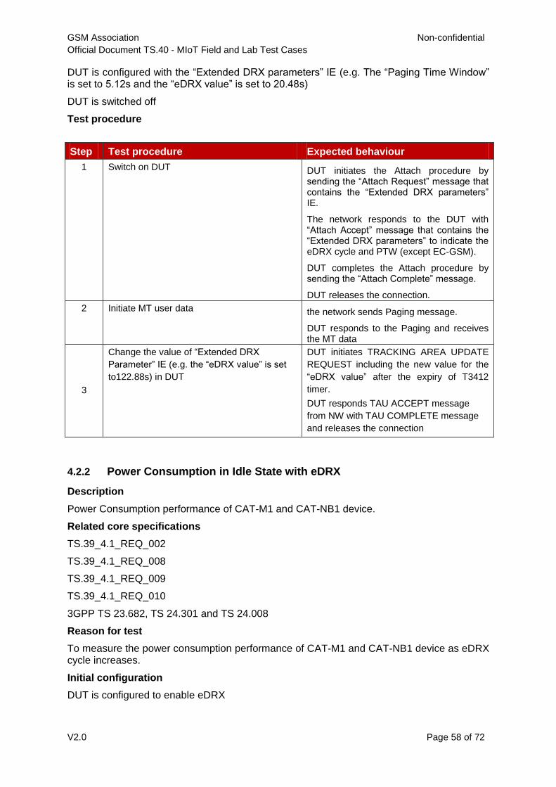
GSM Association Non-confidential
Official Document TS.40 - MIoT Field and Lab Test Cases
V2.0 Page 58 of 72
DUT is configured with the “Extended DRX parameters” IE (e.g. The “Paging Time Window” is set to 5.12s and the “eDRX value” is set to 20.48s)
DUT is switched off
Test procedure
Step Test procedure Expected behaviour
1 Switch on DUT DUT initiates the Attach procedure by sending the “Attach Request” message that contains the “Extended DRX parameters” IE.
The network responds to the DUT with “Attach Accept” message that contains the “Extended DRX parameters” to indicate the eDRX cycle and PTW (except EC-GSM).
DUT completes the Attach procedure by sending the “Attach Complete” message.
DUT releases the connection.
2 Initiate MT user data the network sends Paging message.
DUT responds to the Paging and receives the MT data
3
Change the value of “Extended DRX
Parameter” IE (e.g. the “eDRX value” is set
to122.88s) in DUT
DUT initiates TRACKING AREA UPDATE
REQUEST including the new value for the
“eDRX value” after the expiry of T3412
timer.
DUT responds TAU ACCEPT message
from NW with TAU COMPLETE message
and releases the connection
4.2.2 Power Consumption in Idle State with eDRX
Description
Power Consumption performance of CAT-M1 and CAT-NB1 device.
Related core specifications
TS.39_4.1_REQ_002
TS.39_4.1_REQ_008
TS.39_4.1_REQ_009
TS.39_4.1_REQ_010
3GPP TS 23.682, TS 24.301 and TS 24.008
Reason for test
To measure the power consumption performance of CAT-M1 and CAT-NB1 device as eDRX cycle increases.
Initial configuration
DUT is configured to enable eDRX
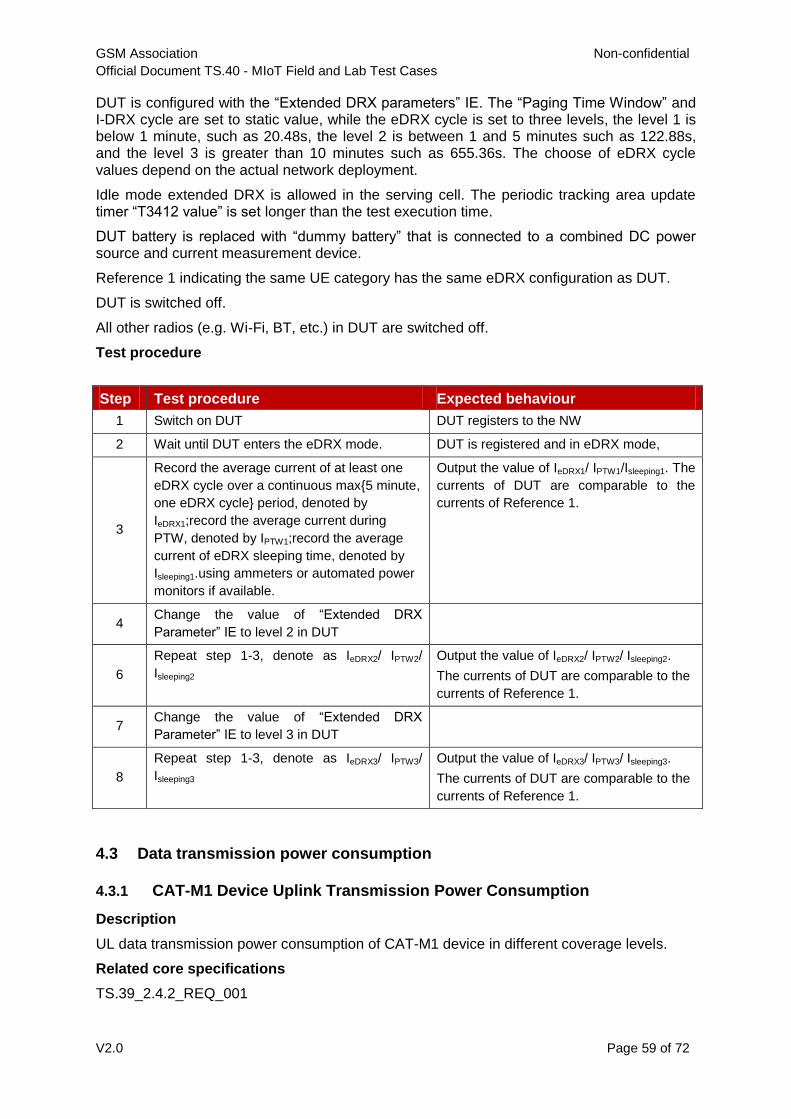
GSM Association Non-confidential
Official Document TS.40 - MIoT Field and Lab Test Cases
V2.0 Page 59 of 72
DUT is configured with the “Extended DRX parameters” IE. The “Paging Time Window” and I-DRX cycle are set to static value, while the eDRX cycle is set to three levels, the level 1 is below 1 minute, such as 20.48s, the level 2 is between 1 and 5 minutes such as 122.88s, and the level 3 is greater than 10 minutes such as 655.36s. The choose of eDRX cycle values depend on the actual network deployment.
Idle mode extended DRX is allowed in the serving cell. The periodic tracking area update timer “T3412 value” is set longer than the test execution time.
DUT battery is replaced with “dummy battery” that is connected to a combined DC power source and current measurement device.
Reference 1 indicating the same UE category has the same eDRX configuration as DUT.
DUT is switched off.
All other radios (e.g. Wi-Fi, BT, etc.) in DUT are switched off.
Test procedure
Step Test procedure Expected behaviour
1 Switch on DUT DUT registers to the NW
2 Wait until DUT enters the eDRX mode. DUT is registered and in eDRX mode,
3
Record the average current of at least one
eDRX cycle over a continuous max{5 minute,
one eDRX cycle} period, denoted by
IeDRX1;record the average current during
PTW, denoted by IPTW1;record the average
current of eDRX sleeping time, denoted by
Isleeping1.using ammeters or automated power
monitors if available.
Output the value of IeDRX1/ IPTW1/Isleeping1. The
currents of DUT are comparable to the
currents of Reference 1.
4 Change the value of “Extended DRX
Parameter” IE to level 2 in DUT
6
Repeat step 1-3, denote as IeDRX2/ IPTW2/
Isleeping2
Output the value of IeDRX2/ IPTW2/ Isleeping2.
The currents of DUT are comparable to the
currents of Reference 1.
7 Change the value of “Extended DRX
Parameter” IE to level 3 in DUT
8
Repeat step 1-3, denote as IeDRX3/ IPTW3/
Isleeping3
Output the value of IeDRX3/ IPTW3/ Isleeping3.
The currents of DUT are comparable to the
currents of Reference 1.
4.3 Data transmission power consumption
4.3.1 CAT-M1 Device Uplink Transmission Power Consumption
Description
UL data transmission power consumption of CAT-M1 device in different coverage levels.
Related core specifications
TS.39_2.4.2_REQ_001

GSM Association Non-confidential
Official Document TS.40 - MIoT Field and Lab Test Cases
V2.0 Page 60 of 72
TS.39_4.1_REQ_011
3GPP TS 36.211, TS 36.331
Reason for test
To measure the UL transmission power consumption of CAT-M1 device in different coverage level.
Initial configuration
For CAT-M1 device supporting CE mode A, performance under coverage level 0/1 is tested.
For CAT-M1 device supporting CE mode B, performance under coverage level 0/1/2/3 is tested.
Reference 1 indicating the same UE category is tested in the similar environment as DUT.
DUT battery is replaced with “dummy battery” that is connected to a combined DC power source and current measurement device.
DUT is switched off.
All other radios (e.g. Wi-Fi, BT, etc.) in DUT are switched off.
Test procedure
Step Test procedure Expected behaviour
1 Switch on DUT and Reference 1 DUT and Reference 1 registers to the NW
2 Wait until DUT and Reference 1 enters the
standby mode.
DUT and Reference 1 is in standby mode,
3
Start power consumption measurement on
DUT and Reference 1:
-Trigger consecutive uplink data transmission
in UDP layer for 3 minutes.
-Record the average current
Record DUT’s and Reference 1 transmit
power and average current.
4
Repeat step 1-3 under different coverage
level.
The average current of DUT under each
coverage level is comparable to the result
for Reference 1;
4.3.2 CAT-NB1 Device Uplink Transmission Power Consumption
Description
UL data transmission power consumption of CAT-NB1 device in different coverage level can meet expectations.
Related core specifications
TS.39_2.4.2_REQ_001
TS.39_4.1_REQ_011
3GPP TS 36.211, TS 36.331
Reason for test
To measure the UL transmission power consumption of CAT-NB1 device in different coverage level.
Initial configuration

GSM Association Non-confidential
Official Document TS.40 - MIoT Field and Lab Test Cases
V2.0 Page 61 of 72
Power consumption performance of Cat-NB1 device under coverage level 0/1/2 is tested.
Sub-carrier spacing of service cell support 15kHz single-tone, 15KHz multi-tone (3/6/12 tones), 3.75kHz single-tone.
Reference 1 indicating the same UE category is tested in the similar environment as DUT.
DUT battery is replaced with “dummy battery” that is connected to a combined DC power source and current measurement device.
DUT is switched off
All other radios (e.g. Wi-Fi, BT, etc.) in DUT are switched off
Test procedure
Step Test procedure Expected behaviour
1 Serving cell is configured to support 3.75kHz
sub-carrier spacing.
The service cell set up successfully
2 Switch on DUT and Reference 1 DUT registers to the NW
3 Wait until DUT enters the standby mode. DUT is registered and in standby mode,
4
Start power consumption measurement on
DUT and Reference 1:
-Trigger consecutive uplink data transmission
in UDP layer for 3 minutes.
-Record the average current
Record DUT’s transmit power and average
current.
5
Repeat step 2-4 under different coverage
level.
The average current of DUT under each
coverage level is comparable to the result
for Reference 1
6
The Sub-carrier spacing is configured to
support 15kHz ST, Repeat step 2-5
The average current of DUT under each
coverage level is comparable to the result
for Reference 1
7
The Sub-carrier spacing is configured to
support 15kHz MT, Repeat step 2-5
The average current of DUT under each
coverage level is comparable to the result
for Reference 1
4.3.3 Downlink Transmission Power Consumption
Description
DL data transmission power consumption of CAT-M1 and CAT-NB1 device in different coverage can meet expectations.
Related core specifications
TS.39_2.4.2_REQ_001
TS.39_4.1_REQ_011
3GPP TS 36.211, TS 36.331
Reason for test
To measure the DL transmission power consumption of CAT-M1 and CAT-NB1 device in different coverage.
Initial configuration
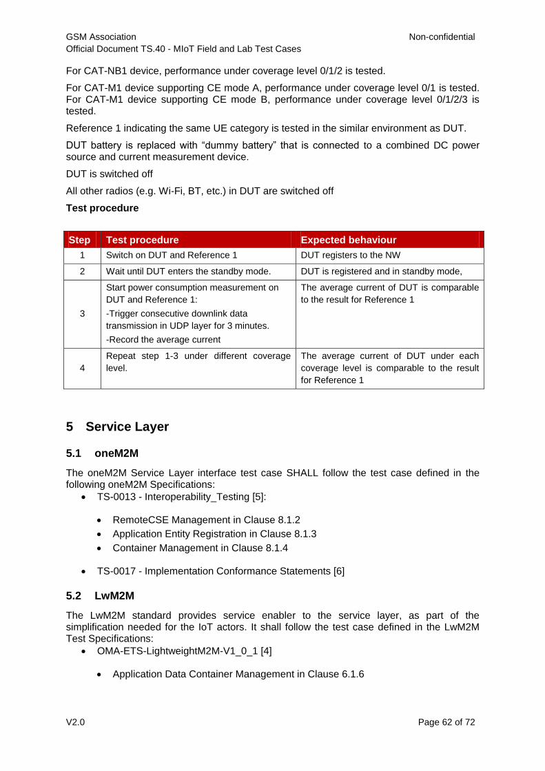
GSM Association Non-confidential
Official Document TS.40 - MIoT Field and Lab Test Cases
V2.0 Page 62 of 72
For CAT-NB1 device, performance under coverage level 0/1/2 is tested.
For CAT-M1 device supporting CE mode A, performance under coverage level 0/1 is tested. For CAT-M1 device supporting CE mode B, performance under coverage level 0/1/2/3 is tested.
Reference 1 indicating the same UE category is tested in the similar environment as DUT.
DUT battery is replaced with “dummy battery” that is connected to a combined DC power source and current measurement device.
DUT is switched off
All other radios (e.g. Wi-Fi, BT, etc.) in DUT are switched off
Test procedure
Step Test procedure Expected behaviour
1 Switch on DUT and Reference 1 DUT registers to the NW
2 Wait until DUT enters the standby mode. DUT is registered and in standby mode,
3
Start power consumption measurement on
DUT and Reference 1:
-Trigger consecutive downlink data
transmission in UDP layer for 3 minutes.
-Record the average current
The average current of DUT is comparable
to the result for Reference 1
4
Repeat step 1-3 under different coverage
level.
The average current of DUT under each
coverage level is comparable to the result
for Reference 1
5 Service Layer
5.1 oneM2M
The oneM2M Service Layer interface test case SHALL follow the test case defined in the following oneM2M Specifications:
TS-0013 - Interoperability_Testing [5]:
RemoteCSE Management in Clause 8.1.2
Application Entity Registration in Clause 8.1.3
Container Management in Clause 8.1.4
TS-0017 - Implementation Conformance Statements [6]
5.2 LwM2M
The LwM2M standard provides service enabler to the service layer, as part of the simplification needed for the IoT actors. It shall follow the test case defined in the LwM2M Test Specifications:
OMA-ETS-LightweightM2M-V1_0_1 [4]
Application Data Container Management in Clause 6.1.6

GSM Association Non-confidential
Official Document TS.40 - MIoT Field and Lab Test Cases
V2.0 Page 63 of 72
6 USIM/eUICC OTA
UICC and USIM device interface test cases SHALL follow the test cases defined in
documents [2] and [3] referenced in Section 1.4.
7 USIM Toolkit
USIM ToolKit device interface test cases SHALL follow the test cases defined in document
[3], referenced in Section 1.4.
8 Antenna Performance
It is expected that Antenna Performance in a free space environment within relevant bands
and areas will be compliant with 3GPP and CTIA specifications, 3GPP TS.34.114 [10],
TS.37.544 [11] and CTIA, OTA Test Plan v 3.6 [12] or later versions of these documents
when available.
Test cases will be agreed with Operators and Manufacturers on a case by case basis.
9 Device Management (LwM2M)
LWM2M test cases SHALL follow the test cases defined in document [4], referenced in
Section 1.4

GSM Association Non-confidential
Official Document TS.40 - MIoT Field and Lab Test Cases
V2.0 Page 64 of 72
10 Mapping of Test Cases to Requirements
MioT Requirements Document Section
Requirement Test Case Comments
2 Basic Operation
TS.39_2.1.2_REQ_001
(Cell selection)
2.1.6 (CAT-NB1)
2.1.7 (CAT-NB1)
2.1.9 (CAT-NB1)
TS.39_2.1.2_REQ_002
(Cell Selection EC-GSM-IoT)
EC-GSM-IoT Test Cases to be defined when Manufacturer support is available.
TS.39_2.2.2_REQ_001
(Attach)
2.1.1 (CAT-M1)
2.1.2 (CAT-M1)
2.1.3 (CAT-M1)
2.1.4 (CAT-NB1)
2.1.5 (CAT-NB1)
2.1.6 (CAT-NB1)
2.1.7 (CAT-NB1)
2.1.8 (CAT-NB1)
2.1.9 (CAT-M1 & CAT-NB1)
3.1.1 (CAT-M1 & CAT-NB1)
3.1.2 (CAT-M1 & CAT-NB1)
4.1.5 (CAT-M1 & CAT-NB1)
TS.39_2.2.2_REQ_002
(Detach)
2.1.10 (CAT-M1 & CAT-NB1)
TS.39_2.2.2_REQ_003
(Attach EC-GSM-IoT)
EC-GSM-IoT Test Cases to be defined when Manufacturer support is available.
TS.39_2.2.2_ REQ_004
(Detach EC-GSM-IoT)
EC-GSM-IoT Test Cases to be defined when Manufacturer support is available.
TS.39_2.2.2_REQ_005
(Attach not accepted by NW)
2.1.9 CAT-M1 & CAT-NB1)
TS.39_2.3.2_REQ_001
(Device Capability Procedure)
2.1.1 (CAT-M1)
2.1.2 (CAT-M1)
2.1.3 (CAT-M1)
2.1.4 (CAT-NB1)
2.1.5 (CAT-NB1)
2.1.6 (CAT-NB1)
2.1.7 (CAT-NB1)
2.1.9 (CAT-M1 & CAT-NB1)
4.1.5 (CAT-M1 & CAT-NB1)
TS.39_2.4.2_REQ_001
(Data Transfer)
2.3.1.1 (CAT-M1 & CAT-NB1)
2.3.1.2 (CAT-M1 & CAT-NB1)
2.3.1.3 (CAT-M1 & CAT-NB1)
2.3.1.4 (CAT-M1 & CAT-NB1)
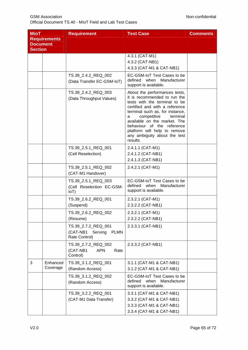
GSM Association Non-confidential
Official Document TS.40 - MIoT Field and Lab Test Cases
V2.0 Page 65 of 72
MioT Requirements Document Section
Requirement Test Case Comments
4.3.1 (CAT-M1)
4.3.2 (CAT-NB1)
4.3.3 (CAT-M1 & CAT-NB1)
TS.39_2.4.2_REQ_002
(Data Transfer EC-GSM-IoT)
EC-GSM-IoT Test Cases to be defined when Manufacturer support is available.
TS.39_2.4.2_REQ_003
(Data Throughput Values)
About the performances tests, it is recommended to run the tests with the terminal to be certified and with a reference terminal such as, for instance, a competitive terminal available on the market. The behaviour of the reference platform will help to remove any ambiguity about the test results.
TS.39_2.5.1_REQ_001
(Cell Reselection)
2.4.1.1 (CAT-M1)
2.4.1.2 (CAT-NB1)
2.4.1.3 (CAT-NB1)
TS.39_2.5.1_REQ_002
(CAT-M1 Handover)
2.4.2.1 (CAT-M1)
TS.39_2.5.1_REQ_003
(Cell Reselection EC-GSM-IoT)
EC-GSM-IoT Test Cases to be defined when Manufacturer support is available.
TS.39_2.6.2_REQ_001
(Suspend)
2.3.2.1 (CAT-M1)
2.3.2.2 (CAT-NB1)
TS.39_2.6.2_REQ_002
(Resume)
2.3.2.1 (CAT-M1)
2.3.2.2 (CAT-NB1)
TS.39_2.7.2_REQ_001
(CAT-NB1 Serving PLMN Rate Control)
2.3.3.1 (CAT-NB1)
TS.39_2.7.2_REQ_002
(CAT-NB1 APN Rate Control)
2.3.3.2 (CAT-NB1)
3 Enhanced Coverage
TS.39_3.1.2_REQ_001
(Random Access)
3.1.1 (CAT-M1 & CAT-NB1)
3.1.2 (CAT-M1 & CAT-NB1)
TS.39_3.1.2_REQ_002
(Random Access)
EC-GSM-IoT Test Cases to be defined when Manufacturer support is available.
TS.39_3.2.2_REQ_001
(CAT-M1 Data Transfer)
3.3.1 (CAT-M1 & CAT-NB1)
3.3.2 (CAT-M1 & CAT-NB1)
3.3.3 (CAT-M1 & CAT-NB1)
3.3.4 (CAT-M1 & CAT-NB1)
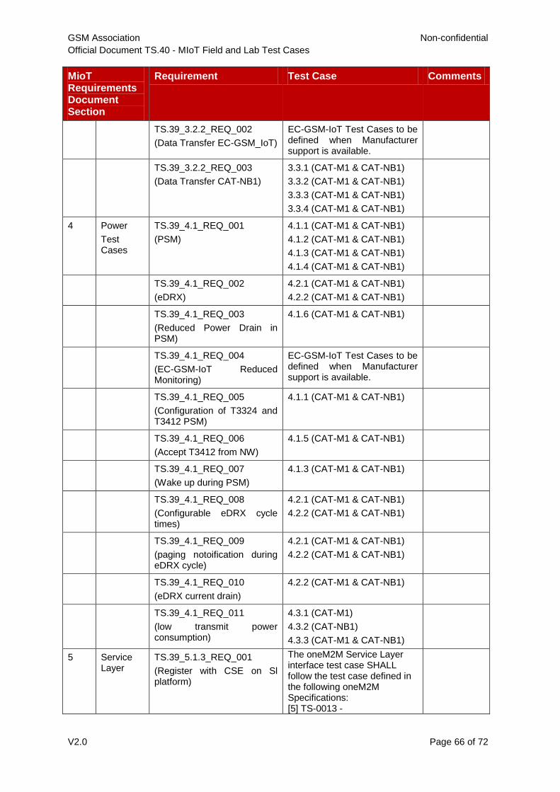
GSM Association Non-confidential
Official Document TS.40 - MIoT Field and Lab Test Cases
V2.0 Page 66 of 72
MioT Requirements Document Section
Requirement Test Case Comments
TS.39_3.2.2_REQ_002
(Data Transfer EC-GSM_IoT)
EC-GSM-IoT Test Cases to be defined when Manufacturer support is available.
TS.39_3.2.2_REQ_003
(Data Transfer CAT-NB1)
3.3.1 (CAT-M1 & CAT-NB1)
3.3.2 (CAT-M1 & CAT-NB1)
3.3.3 (CAT-M1 & CAT-NB1)
3.3.4 (CAT-M1 & CAT-NB1)
4 Power
Test Cases
TS.39_4.1_REQ_001
(PSM)
4.1.1 (CAT-M1 & CAT-NB1)
4.1.2 (CAT-M1 & CAT-NB1)
4.1.3 (CAT-M1 & CAT-NB1)
4.1.4 (CAT-M1 & CAT-NB1)
TS.39_4.1_REQ_002
(eDRX)
4.2.1 (CAT-M1 & CAT-NB1)
4.2.2 (CAT-M1 & CAT-NB1)
TS.39_4.1_REQ_003
(Reduced Power Drain in PSM)
4.1.6 (CAT-M1 & CAT-NB1)
TS.39_4.1_REQ_004
(EC-GSM-IoT Reduced Monitoring)
EC-GSM-IoT Test Cases to be defined when Manufacturer support is available.
TS.39_4.1_REQ_005
(Configuration of T3324 and T3412 PSM)
4.1.1 (CAT-M1 & CAT-NB1)
TS.39_4.1_REQ_006
(Accept T3412 from NW)
4.1.5 (CAT-M1 & CAT-NB1)
TS.39_4.1_REQ_007
(Wake up during PSM)
4.1.3 (CAT-M1 & CAT-NB1)
TS.39_4.1_REQ_008
(Configurable eDRX cycle times)
4.2.1 (CAT-M1 & CAT-NB1)
4.2.2 (CAT-M1 & CAT-NB1)
TS.39_4.1_REQ_009
(paging notoification during eDRX cycle)
4.2.1 (CAT-M1 & CAT-NB1)
4.2.2 (CAT-M1 & CAT-NB1)
TS.39_4.1_REQ_010
(eDRX current drain)
4.2.2 (CAT-M1 & CAT-NB1)
TS.39_4.1_REQ_011
(low transmit power consumption)
4.3.1 (CAT-M1)
4.3.2 (CAT-NB1)
4.3.3 (CAT-M1 & CAT-NB1)
5 Service Layer
TS.39_5.1.3_REQ_001
(Register with CSE on Sl platform)
The oneM2M Service Layer interface test case SHALL follow the test case defined in the following oneM2M Specifications: [5] TS-0013 -

GSM Association Non-confidential
Official Document TS.40 - MIoT Field and Lab Test Cases
V2.0 Page 67 of 72
MioT Requirements Document Section
Requirement Test Case Comments
Interoperability_Testing: RemoteCSE Management in Clause 8.1.2 Application Entity Registration in Clause 8.1.3 Container Management in Clause 8.1.4 [6] TS-0017 - Implementation Conformance Statements
TS.39_5.1.3_REQ_002
(Management by SL platform)
The oneM2M Service Layer interface test case SHALL follow the test case defined in the following oneM2M Specifications: [5] TS-0013 - Interoperability_Testing: RemoteCSE Management in Clause 8.1.2 Application Entity Registration in Clause 8.1.3 Container Management in Clause 8.1.4
[6] TS-0017 - Implementation Conformance Statements
TS.39_5.1.3_REQ_003
(App on cloud side config)
The oneM2M Service Layer interface test case SHALL follow the test case defined in the following oneM2M Specifications: [5] TS-0013 - Interoperability_Testing: RemoteCSE Management in Clause 8.1.2 Application Entity Registration in Clause 8.1.3 Container Management in Clause 8.1.4
[6] TS-0017 - Implementation Conformance Statements
TS.39_5.2.3_REQ_001 The LwM2M standard provides service enabler to the service layer, as part of the simplification needed for the IoT actors. It shall follow the test case defined in the LwM2M Test Specifications: OMA-ETS-LightweightM2M-
V1_0_1[4]
Application Data Container Management in Clause 6.1.6
6 SIM/eUICC OTA
TS.39_6.1_REQ_001 UICC and USIM device interface test cases SHALL
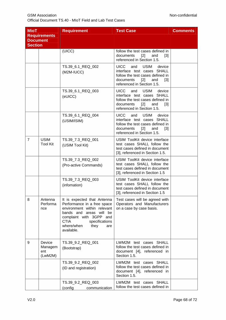
GSM Association Non-confidential
Official Document TS.40 - MIoT Field and Lab Test Cases
V2.0 Page 68 of 72
MioT Requirements Document Section
Requirement Test Case Comments
(UICC) follow the test cases defined in documents [2] and [3] referenced in Section 1.5.
TS.39_6.1_REQ_002
(M2M-IUCC)
UICC and USIM device interface test cases SHALL follow the test cases defined in documents [2] and [3] referenced in Section 1.5.
TS.39_6.1_REQ_003
(eUICC)
UICC and USIM device interface test cases SHALL follow the test cases defined in documents [2] and [3] referenced in Section 1.5.
TS.39_6.1_REQ_004
(USIM/ISIM)
UICC and USIM device interface test cases SHALL follow the test cases defined in documents [2] and [3] referenced in Section 1.5.
7 USIM Tool Kit
TS.39_7.3_REQ_001
(USIM Tool Kit)
USIM ToolKit device interface test cases SHALL follow the test cases defined in document [3], referenced in Section 1.5.
TS.39_7.3_REQ_002
(Pro-active Commands)
USIM ToolKit device interface test cases SHALL follow the test cases defined in document [3], referenced in Section 1.5
TS.39_7.3_REQ_003
(infomation)
USIM ToolKit device interface test cases SHALL follow the test cases defined in document [3], referenced in Section 1.5
8 Antenna Performance
It is expected that Antenna Performance in a free space environment within relevant bands and areas will be complaint with 3GPP and CTIA specifications where/when they are available.
Test cases will be agreed with Operators and Manufacturers on a case by case basis.
9 Device Management (LwM2M)
TS.39_9.2_REQ_001
(Bootstrap)
LWM2M test cases SHALL follow the test cases defined in document [4], referenced in Section 1.5.
TS.39_9.2_REQ_002
(ID and registration)
LWM2M test cases SHALL follow the test cases defined in document [4], referenced in Section 1.5.
TS.39_9.2_REQ_003
(config communication
LWM2M test cases SHALL follow the test cases defined in

GSM Association Non-confidential
Official Document TS.40 - MIoT Field and Lab Test Cases
V2.0 Page 69 of 72
MioT Requirements Document Section
Requirement Test Case Comments
parameter – normal function) document [4], referenced in Section 1.5.
TS.39_9.2_REQ_004
(config communication parameter – fallback)
LWM2M test cases SHALL follow the test cases defined in document [4], referenced in Section 1.5.
TS.39_9.2_REQ_005
(firmware update)
LWM2M test cases SHALL follow the test cases defined in document [4], referenced in Section 1.5.
TS.39_9.2_REQ_006
(replace configured comm parameters)
LWM2M test cases SHALL follow the test cases defined in document [4], referenced in Section 1.5.
TS.39_9.2_REQ_007
(security info update ota)
LWM2M test cases SHALL follow the test cases defined in document [4], referenced in Section 1.5.
TS.39_9.2_REQ_008
(report APP health information)
LWM2M test cases SHALL follow the test cases defined in document [4], referenced in Section 1.5.
TS.39_9.2_REQ_009
(report location)
LWM2M test cases SHALL follow the test cases defined in document [4], referenced in Section 1.5.
TS.39_9.2_REQ_010
(data transfer to server)
LWM2M test cases SHALL follow the test cases defined in document [4], referenced in Section 1.5.
TS.39_9.2_REQ_011
(provide host information details)
LWM2M test cases SHALL follow the test cases defined in document [4], referenced in Section 1.5.
TS.39_9.2_REQ_012
(basic diagnostic capabilities)
LWM2M test cases SHALL follow the test cases defined in document [4], referenced in Section 1.5.
TS.39_9.2_REQ_013
(basic observe/notify capabilities)
LWM2M test cases SHALL follow the test cases defined in document [4], referenced in Section 1.5.
TS.39_9.2_REQ_014
(basic queue capabilities)
LWM2M test cases SHALL follow the test cases defined in document [4], referenced in Section 1.5.
TS.39_9.2_REQ_015
(report PSM information)
LWM2M test cases SHALL follow the test cases defined in

GSM Association Non-confidential
Official Document TS.40 - MIoT Field and Lab Test Cases
V2.0 Page 70 of 72
MioT Requirements Document Section
Requirement Test Case Comments
document [4], referenced in Section 1.5.
TS.39_9.2_REQ_016
(update PSM)
LWM2M test cases SHALL follow the test cases defined in document [4], referenced in Section 1.5.
TS.39_9.2_REQ_017 LWM2M test cases SHALL follow the test cases defined in document [4], referenced in Section 1.5.
TS.39_9.2_REQ_018 LWM2M test cases SHALL follow the test cases defined in document [4], referenced in Section 1.5.
TS.39_9.2_REQ_019 LWM2M test cases SHALL follow the test cases defined in document [4], referenced in Section 1.5.
GSM Association Non-confidential
Official Document TS.40 - MIoT Field and Lab Test Cases
V2.0 Page 71 of 72
Annex A Individual Test Scenario Classification and Proforma
This Annex contains the individual classification (i.e. whether a test applies to Field Test, Lab Test or both) of every single test scenario. It can also be used as a blank proforma to record the results of an individual test scenario.
Worksheet in TS-40
V2.0.xlsx

GSM Association Non-confidential
Official Document TS.40 - MIoT Field and Lab Test Cases
V2.0 Page 72 of 72
Annex B Document Management
B.1 Document History
Version Date Section
No
Brief Description of
Change
Approval
Authority
Editor /
Company
1.0 18
November
2016
New PRD (CLP23 v0.1). TCJWG/PSMC
David Hills
2.0 December
2017
All New PRD (TS.40 v2.0)
Initial official release of this
document, approved by GSMA
Plenary (TSG#30)
TSG / TG
Petra Rauer
Vodafone
B.2 Other Information
Type Description
Document Owner Terminal Steering Group
Editor / Company Paul Gosden, GSMA
It is our intention to provide a quality product for your use. If you find any errors or omissions,
please contact us with your comments. You may notify us at [email protected]
Your comments or suggestions & questions are always welcome.


