A LARGE 100 MW PULSED MAGNETIC COIL FOR FUSION RESEARCH
M. Huguet, P. H. Rebut, and A. TorossianASSOCIATION EURATOM-CEA SUR LA FUSION
Departement de Physique du Plasma et de la Fusion ControleeCentre d'Etudes Nucleaires
Boite Postale No.6, 92 FONTENAY-AUX-ROSES (France)
M. MeierSociete OERLIKON
Abstract
The main toroidal magnet for the TFR fusion device which is now being assembled at Fontenay-auxRoses is described. The magnet consists of a 98 em major'radius and 30 em minor radius torus. It iscomposed of 24 oil-cooled Bitter-type coils. Each coil consists of 35 turns of full-hard copper insulated with kapton The total weight of the 24 coils is about 20 tons. A center-line field of 60 kG isgenerated with a current of 35 000 A. The field corrugations along the center line do not exceed 0.5%.With a peak power input of 120 MW and for a mean pulse length of 1.5 sec, the energy delivered to themagnet during one pulse is 150 MJ, and the magnetic energy stored is 40 MJ. The repetition rate is onepulse every 4 minutes.
1
mllllll!lllllll!!!I!!I!!::!!!I!!!!
4 r-----p···mm·······~=~
ELEVATION VIEW
1l--------(
PLAN VIEW
\oI---I-~"'~"'~'"+----{ 7
6
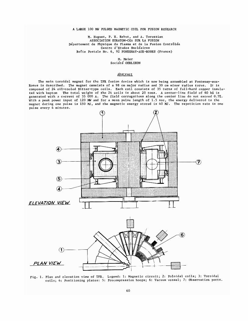
Fig. 1. Plan and elevation view of TFR. Legend: 1: Magnetic circuit; 2: Poloidal coils; 3: Toroidalcoils; 4: Positioning plates: 5: Precompression hoops; 6: Vacuum vessel; 7: Observation ports.
60
I. Description of the TFR Device COOLIN G SLITSThe TFR fusion device which is now being as
sembled at Fontenay-aux-Roses belongs to theTokamak family. Tokamak devices have been developed in the USSR and have produced the closest approach until now to parameters needed for a controlled thermonuclear reaction.
A general view of the TFR device is shown onFig. 1. TFR is a transformer, the secondary ofwhich is the plasma. Primary coils (Be coils)initiate the gaseous discharge in the toroidalvacuum chamber, and induce a large current in theplasma. By ohmic heating, the temperature of theplasma rises, and by pinch effect, the plasma isconfined. However the confinement is unstable anda strong toroidal magnetic field is required tocounteract the instabilities. TFR is mainly composed of:
- a vacuum system (toroidal chamber; observationport and pumps),
- a transform2r (poloidal coils; a magnetic circuit is used to improve the coupling betweenthe poloidal coils and the plasma),
- a toroidal winding for stabilization.
This paper describes the stabilizing winding.
0 -~ --• ~~ . -• -00 --0
o 0 --0 0<:)<:)
~ -- -0• (f? •
• •• 0 0 •0 c::::::::> c::::::) c:=> ~ •
0 0 0 0 •
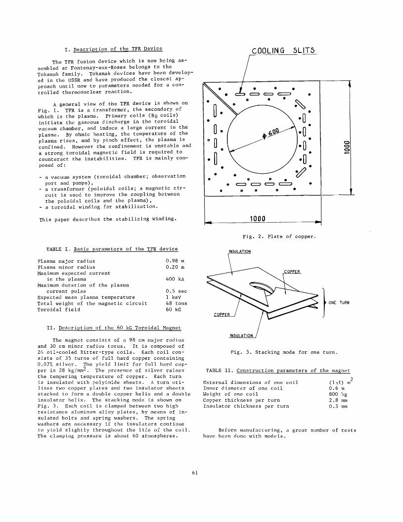
L 1000 JFig. 2. Plate of copper.
TABLE I. Basic parameters of the TFR device
II. Description of the 60 kG Toroidal Magnet
The magnet consists of a 98 em major radiusand 30 em minor radius torus. It is composed of24 oil-cooled Bitter-type coils. Each coil consists of 35 turns of full hard copper containing0.07% silver. The yield limit for full hard copper is 28 kg/mm2 . The presence of silver raisesthe tempering temperature of copper. Each turnis insulated with polyimide sheets. A turn utilizes two copper plates and two insulator sheetsstacked to form a double copper helix and a doubleinsulator helix. The stacking mode is shown onFig. 3. Each coil is clamped between two highresistance aluminum alloy plates, by means of insulated bolts and spring washers. The springwashers are necessary if the insulators continueto yield slightly throughout the life of the coil.The clamping pressure is about 60 atmospheres.
2(l xl) m0.6 m800 :<g2.8 mm0.3 mm
} ONE TURN
Fig. 3. Stacking mode for one turn.
TABLE II. Construction parameters of the magnet
Before manufacturing, a great number of testshave been done with models.
External dimensions of one coilInner diameter of one coilWeight of one coilCopper thickness per turnInsulator thickness per turn
0.98 m0.20 m
0.5 secI keV48 tons60 kG
400 kA
plasma major radiusplasma minor radiusMaximum expected current
in the plasmaMaximum duration of the plasma
current pulseExpected mean plasma temperatureTotal weight of the magnetic circuitToroidal field
61

10000 1000
Fig. 4. One TFR coil
R em
130
35 000 A3500 V4500 V120 MW
150 MJ0.07 [)0.063 H5.4 V
INNER DIAMETER orTHE COILS
Toroidal field corrugations.Fig. 6.
~B= Bmax - Bmin where Bmax is the value of Bin the midplane of a coil, and Bmin the value of Bbetween two coils.
TABLE III. Electrical parameters
B is the field mean value along a closedfie Id line.
IV. Toroidal Magnetic Field
6B is the variations of B along a closedfield line.
With a magnet current of 35 000 A a 60 kGfield is generated along a circumference of 98 emradius. The maximum field, along a 70 em radiuscircumference is 80 kG. The magnetic energy storedin the magnet is 40 MJ.
Nominal currentNominal voltagePeak voltagePeak powerEnergy dissipated in the magnet
per pulseResistance of the magnetInductancePeak voltage per turn
Resulting from the gaps between the coils thefield intensity along a field line is not constant.The field corrugations are shown in Fig. 6. Thisfigure shows the cross sections of the surfaceswhere ~B/B is constant.
The mechanical resistance of the coils hasbeen verified with a scale 1/3 coil model. Duringthis test a pulsed 500 atmospheres hydraulic pressure has been applied along the inner diameter ofthe coil model. The stresses in the copper reached13 kg/mm2 . No damage was found after 10 000 cycles.
III. Electrical Operation Parameters
20000 2000
- mean current density 3.5 times higher than in theTFR coils,
- adiabatic temperature rise of more than 200oC.
The magnet operates in a pulsed regime and isenergized by an alternator coupled to a flywheel.The waveforms of the voltage and current deliveredby the rectifiers are shown on Fig. 5. The repetition rate is one pulse every 4 minutes.
I U(A) (V)
40000 4000
30000 3000
The more interesting tests have been donewith the co-operation of the Magnet Laboratory atCambridge. The model coil has been powered withthe pulsed power generator of the laboratory. Thetest conditions were severe:
The coils have been ordered from the CEM(Compagnie Electro-Mecanique) and manufactured bythe Societe Oerlikon. One of , the main problemsduring the stacking of the coils was that of cleanliness, because the polyimide sheets are veryeasily perforated by small metallic particles.
Fig. 5. Voltage and current in the magnet.
0,5 1.5 2 2,5
t uc,The 24 coils are all connected in series and
they produce a spurious field component parallel tothe torus axis. This component is almost cancelled
62
The efficiency of the cooling system dependsto a large extent on the physical properties ofthe coolant. By assuming that the heat transfercoefficient from the copper of the coils to theturbulent pyralene flow is described by the classical relation
by the return current which flows in a conductorplaced just at the outer surface of the coils.However a correction is necessary because at thebeginning of the plasma discharge when the breakdown occurs it is very important for the toroidalfield lines to be closed. The Be coils and theirpower supplies have been designed in order to cancel this spurious field. N
u0.023
V. Cooling System
The thermal parameters of the magnet aregiven in the following table.
TABLE IV. Thermal parameters
where Nu ' Pr and Re are the dimensionless Nusselt,Prandtl and Reynolds numbers.
We find that the temperature difference between copper and coolant is
l:1T = P A B
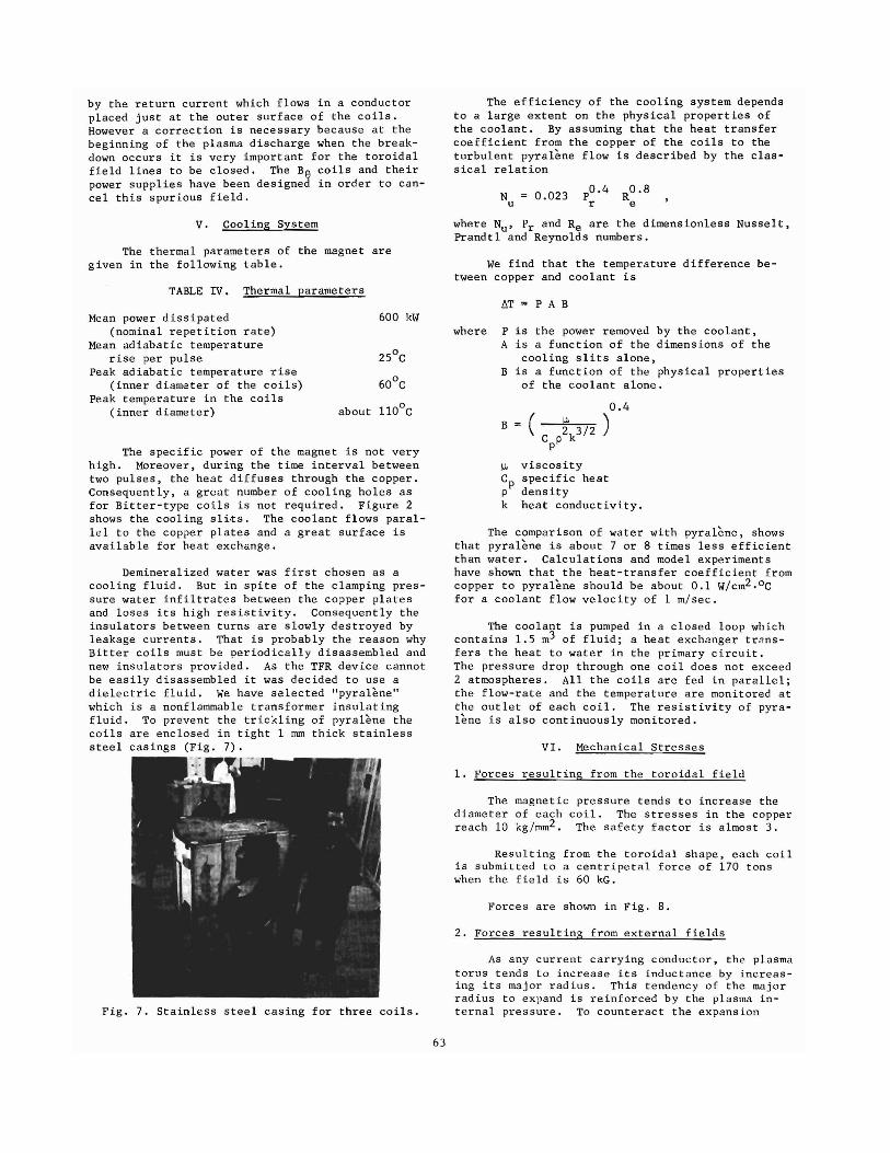
Fig. 7. Stainless steel casing for three coils.
The specific power of the magnet is not veryhigh. Moreover, during the time interval betweentwo pulses, the heat diffuses through the copper.Consequently, a great number of cooling holes asfor Bitter-type coils is not required. Figure 2shows the cooling sli,ts. The coolant flows parallel to the copper plates and a great surface isavailable for heat exchange.
IJ. viscosityCp specific heatp densityk heat conductivity.
As any current carrying conductor, the plasmatorus tends to increase its inductance by increasing its major radius. This tendency of the majorradius to expand is reinforced by the plasma internal pressure. To counteract the expansion
2. Forces resulting from external fields
Forces are shown in Fig. 8.
The comparison of water with pyralene, showsthat pyralene is about 7 or 8 times less efficientthan water. Calculations and model experimentshave shown that the heat-transfer coefficient fromcopper to pyralene should be about 0.1 W/cm2 . oCfor a coolant flow velocity of 1 m/sec.
Resulting from the toroidal shape, each coilis submitted to a centripetal force of 170 tonswhen the field is 60 kG.
VI. Mechanical Stresses
1. Forces resulting from the toroidal field
The magnetic pressure tends to increase thediameter of each coil. The stresses in the copperreach 10 kg/mm2 . The safety factor is almost 3.
The coolant is pumped in a closed loop whichcontains 1.5 m3 of fluid; a heat exchanger trAnsfers the heat to water in the primary circuit.The pressure drop through one coil does not exceed2 atmospheres. All the coils are fed in parallel;the flow-rate and the temperature are monitored atthe outlet of each coil. The resistivity of pyralene is also continuously monitored.
where P is the power removed by the coolant,A is a function of the dimensions of the
cooling slits alone,B is a function of the physical properties
of the coolant alone.
600 kWMean power dissipated(nominal repetition rate)
Mean adiabatic temperaturerise per pulse
Peak adiabatic temperature rise(inner diameter of the coils)
Peak temperature in the coils(inner diameter)
Demineralized water was first chosen as acooling fluid. But in spite of the clamping pressure water infiltrates between the copper platesand loses its high resistivity. Consequently theinsulators between turns are slowly destroyed byleakage currents. That is probably the reason whyBitter coils must be periodically disassembled andnew insulators provided. As the TFR device cannotbe easily disassembled it was decided to use adielectric fluid. We have selected "pyralEme"which is a nonflammable transformer insulatingfluid. To prevent the trickling of pyralene thecoils are enclosed in tight 1 rom thick stainlesssteel casings (Fig. 7).
'~:r
63

3. Forces ar~s~ng in the case of an electricalfailure
CI)
x«CI)
:::>0::o1-,
380 Tona
Z80 Tona
210 Tona
The most dangerous failure is the short circuit of one coil. In this case, the coils adjacentto the failing ones are pushed apart by very largeforces.
If the short circuit occurs at the beginningof the current pulse, the current in the shortcircuited coil flows in the direction opposite tothe main current, but the time constant of thefailing coil is long and the current cannot reachan appreciable value. Moreover the control system(see Section VIII) can detect the failure and thepower supply is switched off.
If the short circuit occurs when the currentreaches its maximum value, the forces can be pessimistically evaluated by assuming that no currentflows in the failing coil. In this case, the distribution of forces is shown in Fig. 10.
Fig. 8. Dynamic loading of one coil.FIl; 26 Tim
h'f:o-"'5i":'rl- fll.163 Tim
-'f-TORU.s AXIS
VII. Mechanical Structure
Fig. 10. Additional forces arising in case of ashort circuit of one coil. The forcesare given in tons per meter.
The problem is to withstand every force whilemaintaining an accurate alignment of the coils.
rORCE
fIELD (1500 G) -t/,~
><0«
IF)
::::>,0::oI-
280 Ton$
[ QUILIBRIUM
t
rORCE
,EQUILIBRIUM fiELD (1500 G)
Fig. 9. Equilibrium field torque.
forces, a magnetic field whose lines of force areparallel to the torus axis is required. For theTFR devices, the "equilibrium field" of 1500 G isproduced by the Be coils. This field tends torotate each coil of the toroidal magnet with atorque of 7.5 tons meter (Fig. 9).
The toroidal centering force of 170 tons oneach coil is supported by the cylindrical core ofthe magnetic circuit. The core has been speciallydesigned in order to sustain the pressure of thecoils. It is composed of magnetic sheets, stackedradially and bounded with epoxy resin. A filamentwound fiberglass sheath encloses the magnetic sheets.Flat surfaces have been machined in front of each
64

COIL N'Z
F" AlLURE D( lECTINGSYSTEM
TOROIDAL COIL N' ZTOROIDAL COIL N"1
i--- ---!-- -~i COILN'1
L---~-i--~ rUrAILURE D(lE-ClINGS II 5Y5TEM
Be
Forces resulting from an electrical failureare held by wedges placed between the coils insuch a way as to form a closed arch. The wedgescross over some observation holes of the vacuumchamber.
coil, in order to ensure a good support. A precompression of all the coils against the core isaccomplished by two steel hoops, and a system ofwedges between the hoops and the outer surfacesof the coils. Due to the temperature rise andmechanical stresses, the expansion of the diameters of the coils is about 1.5 rom during a pulse.The supports have been designed in order to offera minimum friction to radial displacements.
For the positioning of the coils, two largecircular aluminum plates have been machined witha great precision. The winding is clamped betweenthe lower and the upper plate by a great number ofhigh resistance steel tie-rods. The two platesare able to stand the torques resulting from theequilibrium field.
Fig. 11. Short-circuited turn detection system.Legend: S ferromagnetic switch
BC bias ing coil.The field directions are shown by thearrows.
VIII. Detection of the Electrical Failures
Two cases of electrical failure have beenconsidered: arcing to ground and short circuit ofone or several turns.
In every case, the circuit breaker betweenthe alternator and the rectifiers is automaticallyopened.
1. Detection of arcing to ground
The system is shown in Fig. 11. Small coaxial coils produce fields in opposite directions.In case of a failure, the resulting field closesthe ferromagnetic switch. The sensitivity is improved by biasing the switch with an auxiliarycoil. Two systems with opposite biasings arenecessary. The sensitivity is adjusted by meansof the bias current. The system is able to detecta variation of 1% in the voltage of one coil.
The mid-point of the winding is connected tothe ground through a 100 0 resistor. Duringnormal operation no current flows through thisresistor. A possible arcing to ground is detectedby measuring the current flowing in the resistor.
2. Detection of the short circuit of one orseveral turns
If a short circuit of one or several turnsoccurs, the resistance and especially the inductance of the failing coil decreases. Consequently, the failure can be detected by continuouslycontrolling the voltage of each coil.
The method used is to compare the voltagesof two coils. The problem is complicated by theinduced currents which can flow through metallicstructures (such as the observation ports of themetallic vacuum chamber). The inductance of onecoil is indeed a function of the inductive couplingbetween the coil and these structures. Consequently the coils have been associated symmetricallywith respect to the currents induced in thestructures.
65


