1 of 25
MODAF-M04-003
MINISTRY OF DEFENCE
MOD Architectural Framework
Concept of Use
Draft 0.2 29th September 2004
Prepared by:- Mr Dave Mawby MODAF Technical Consultant Approved by:-
THIS DOCUMENT IS THE PROPERTY OF HER BRITANNIC MAJESTY’S GOVERNMENT, and is issued for the information of such persons only as need to know its contents in the course of their official duties. Any person finding this document should hand it to a British Forces unit or to a Police Station for its safe return to the SECURITY OFFICE, DEFENCE PROCUREMENT AGENCY, ABBEY WOOD, BRISTOL, BS34 8JH, with details of how and when found. THE UNAUTHORISED RETENTION OR DESTRUCTION OF THIS DOCUMENT MAY BE AN OFFENCE UNDER THE UNITED KINGDOM OFFICIAL SECRETS ACT OF 1911-89.
2 of 25
RECORD OF CHANGES
This page will be updated and re-issued with each amendment. It provides an authorisation for the amendment and a checklist to the current amendment number.
Issue No. Date Revision Details Draft 0.1
Draft 0.2
8th Sep 2004
29th Sep 2004
First Draft Issue: New document to provide guidance on the concept of use for MODAF throughout a variety of MOD processes and lifecycle stages. Updated to reflect policy to rename Strategic Views as Strategic Views. Added section on architecture-based analysis. This version is an unapproved draft provided for initial guidance only.
3 of 25
Introduction
Understanding how MODAF supports the MOD processes
The MOD Architectural Framework (MODAF) is being developed as a critical enabler of NEC1, which enables improved interoperability and should realise significant cost avoidance benefits through improved efficiency of the MOD acquisition processes and reduction in the amount of rework required to deliver interoperability and integration. The full rationale behind the development of MODAF and its expected benefits are described in more detail within the MODAF PID and its associated business case. However, in order to deliver thee benefits MODAF must achieve full integration with the MOD processes and acquisition lifecycle. This MODAF concept of use explains how the various MODAF views are likely to support the various MOD stakeholders and processes throughout the entire lifecycle. The MODAF concept of use has been developed largely from responses received from a wide variety of MOD stakeholders during the MODAF community of interest (COI) workshops2. This will be validated further through the MODAF pilot projects and reviews of the MODAF products (eg MODAF handbook and COI deskbooks) as they develop.
Aim The aim of this paper is to give an overview of how MODAF views might be
used to support various MOD processes and stakeholders. It is provided for discussion and communications of the MODAF intent while the full MODAF products are being developed. This paper therefore provides interim guidance only and will be superseded by the MODAF handbook and COI deskbooks when available.
Scope and Exclusions
This paper only covers the relationship of MODAF to the MOD processes and stakeholders that were represented through the COI workshops and other MODAF briefings. Although it is believed that these processes and stakeholders reflect the core of the MOD acquisition lifecycle there are likely to be important processes and stakeholders that have been omitted. This is not deliberate and any such omissions should be reported to the MODAF team for inclusion in subsequent issues of this paper and / or the MODAF handbook and COI deskbooks. This MODAF concept of use is based upon the current MOD acquisition lifecycle and processes. Further work is being undertaken to enhance some aspects of these – such as the Acquisition for NEC (AfNEC) change programme and enterprise architecture (EA). MODAF will continue to offer significant benefits to the MOD under these circumstances and could indeed be a critical enabler of such changes. The relationship of MODAF to AfNEC and EA is explored in a separate white paper3.
1 CM(IS) NEC Next Steps paper of April 2003. 2 MODAF Feedback from COI Workshops, MODAF-M02-002, September 2004. 3 Use of MODAF in an Enterprise Architecture approach, MODAF-M04-004, September 2004.
4 of 25
This paper does not explain the full contents of each MODAF view – for this information it is suggested that the reader consults the relevant MODAF4,5 / DODAF6 documentation. For reference, a summary of the MODAF views is included at Appendix A along with the likely roles and responsibilities as outlined in this paper.
Purpose of Architectures
Understanding what role the architecture is to fulfil
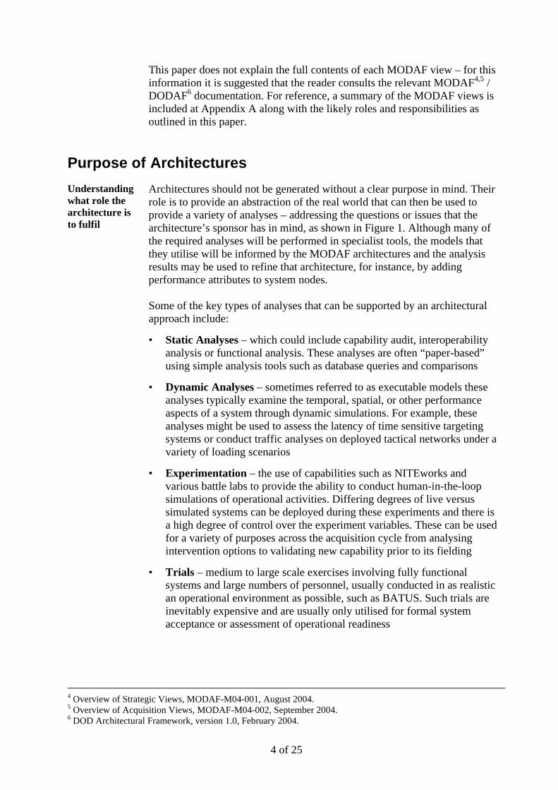
Architectures should not be generated without a clear purpose in mind. Their role is to provide an abstraction of the real world that can then be used to provide a variety of analyses – addressing the questions or issues that the architecture’s sponsor has in mind, as shown in Figure 1. Although many of the required analyses will be performed in specialist tools, the models that they utilise will be informed by the MODAF architectures and the analysis results may be used to refine that architecture, for instance, by adding performance attributes to system nodes. Some of the key types of analyses that can be supported by an architectural approach include:
• Static Analyses – which could include capability audit, interoperability analysis or functional analysis. These analyses are often “paper-based” using simple analysis tools such as database queries and comparisons
• Dynamic Analyses – sometimes referred to as executable models these analyses typically examine the temporal, spatial, or other performance aspects of a system through dynamic simulations. For example, these analyses might be used to assess the latency of time sensitive targeting systems or conduct traffic analyses on deployed tactical networks under a variety of loading scenarios
• Experimentation – the use of capabilities such as NITEworks and various battle labs to provide the ability to conduct human-in-the-loop simulations of operational activities. Differing degrees of live versus simulated systems can be deployed during these experiments and there is a high degree of control over the experiment variables. These can be used for a variety of purposes across the acquisition cycle from analysing intervention options to validating new capability prior to its fielding
• Trials – medium to large scale exercises involving fully functional systems and large numbers of personnel, usually conducted in as realistic an operational environment as possible, such as BATUS. Such trials are inevitably expensive and are usually only utilised for formal system acceptance or assessment of operational readiness
4 Overview of Strategic Views, MODAF-M04-001, August 2004. 5 Overview of Acquisition Views, MODAF-M04-002, September 2004. 6 DOD Architectural Framework, version 1.0, February 2004.

5 of 25
Real WorldReal World
ArchitecturesArchitecturesArchitecturesOV-2
: NMJIC
: JFC(JOC/JIC) : JFACC(AOC, 609AIS)
: DJFLCC(DOCC, 513ACE)
: MAW
: WOC
6: Target Nominations
1: BDA Reports8: Recommend Restrike
2: Munitions Effects Assessment5: Target Nominations
4: Target Nominations
9: Recommend Restrike
3: Target Nominations
10: Recommend Restrike
7: Target Nominations
11: Recommend Restrike
OV-2
: NMJIC
: JFC(JOC/JIC) : JFACC(AOC, 609AIS)
: DJFLCC(DOCC, 513ACE)
: MAW
: WOC
6: Target Nominations
1: BDA Reports8: Recommend Restrike
2: Munitions Effects Assessment5: Target Nominations
4: Target Nominations
9: Recommend Restrike
3: Target Nominations
10: Recommend Restrike
7: Target Nominations
11: Recommend Restrike
CAPABILITY FUNCTION
Decision SupportSituational Awareness
CCIRM JOCS (IPM only)/GP3(HQ ARRC only)Op Planning JOCS (IPM only)/GP3(HQ ARRC only)Intelligence JOCS (IPM only)/GP3(HQ ARRC only)
InteroperabilityJoint Strategic Intelligence LOCE MIDB/LOCEOperational Intelligence INT-C INTELWEB?Joint Logisitcs JCS LogNATO C2 & Int NIUTS/NSWANNATO CommsAllied Interoperability MIP Messaging/US-GCCSMaritime RNCSS/LPD(R)/T22/T23/T42/CVS/T45Air C2/Coord RAFCCIS/JFAC
Functional Planning SupportCSS AP3
Medical SGISNBC BRACIS/BATESBRACIS NT NBC BISA/BATES NBC BISAGBAD AD BriC IGBAD IOCFire Support FCAAviation C2Aviation Logistics Support ACCESSEngineer/EODComms Management BCMS/CORMORANT CMSIS Management II IOC/II FOC DBL II FOC
InteroperabilityNATO ADAllied Fire Support AFATDS AFATDS II
JTF/ARRC IS JOCS/E-IARRCIS MLI/RNCSSFmn IS BOWMAN IOC/ATacCS/II EOCBG & below IS Platform BISA IOC/FOC/BGTIIn barracks IS DIIUnit IS DIIIndividual IS BOWMAN PUDT, BRAD FIST/BOWMAN PUDT, BRAD
FALCON CMS/BCMS/CORMORANT CMS
CWAN (IPM only?)
JFAC (IPM only)RNCSS/LPD(R)/T22/T23/T42/CVSUS-GCCS (IPM only)
AP3/QP24
IS INFRASTRUCTUREJOCS/E-IARRCIS/RNCSS
Epoch 2 (2004-2007)
JCS Log
JOCS/G2 BISA/GP3 (HQ ARRC only)
JOCS/E-IARRCIS MLI/RNCSS
ACCS LOC1
Epoch 3 (2006-2011)
AM BISA?
Log C4I?/G1 BISA?
DBL II IOC/DBL II FOC/BOWMAN FOC
Bi-SCAIS
UNICOM/EMS
COMMAND BATTLESPACE MANAGEMENT
CASH (SLI/RLI)/EMS
ADCISFCBISA/IFPA
ASH
BATES
MAKEFAST/EOD BISA
ATacCSATacCS
ACCESSWAH-64 GSS
Epoch 1 (Now - 2008)
CRONOS (IPM only)
JOCS/ComBAT/GP3 (HQ ARRC only)JOCS/ComBAT/GP3 (HQ ARRC only)
BMETS/JOCS/GP3(HQ ARRC only)/RNCSS
ComBAT/GP3 (HQ ARRC only)/JOCS/RNCSS/HVM SIFF/GBAD RAP IOC
BMETS/JOCS/BSAM/GP3(HQ ARRC only)/RNCSS/HVM SIFF
ATacCS
StV-3
TRM’s Interfaces View
Applicat ion Software
MISSION AREA APPLICATIONS
SERVICE AREA SERVICE STANDARD
All Web Appl icat ions Interface 4D: (Application to Web Server) Common Gateway Interface (CGI) 1.1, NCSA Software Development
SUPPORT APPLICATIONS
SER VICE AREA SERVICE STANDARD
Interface 4L: HTML 4.0 Specif icat ion, W3C Recommendation (Hypertext Markup Language)
Personal Messaging Interface 4D: (E -Mail Client to E-Mail Server) IETF Standard 10/RFC-821/RFC-1869/RFC-1870 Simple Mail Transfer Protocol (SMTP) Service Extensions, November 1995 TV-1 SV-1
,2& )2&
:DWFKNHHSHU
2 F W 'HF
51&66
%/'&66,)/3'5
)DOFRQ,QFUHPHQW$
0DLQ*DWH,QF$,QLWLDO*DWH,QF%,QF$'0&WW/HW )LHOG7ULDOV 'HOLYHU7UDQFKH 'HOLYHU7UDQFKH 'HOLYHU7UDQFKH,QF$,6' ,QF$,6'0DLQ*DWH,QF%
'HOLYHU7UDQFKH
'HOLYHU7UDQFKH'HOLYHU7UDQFKH
)DOFRQ,QFUHPHQW%
'0&WW/HW
)DOFRQ,QFUHPHQW&
,QLWLDO*DWH,QF&
)LHOG7ULDOV,QF%'HOLYHU7UDQFKH'HOLYHU7UDQFKH'HOLYHU7UDQFKH'HOLYHU7UDQFKH'HOLYHU7UDQFKH'HOLYHU7UDQFKH
'HOLYHU57768SJUDGH
'HOLYHU7UDQFKH 'HOLYHU7UDQFKH
'HOLYHU7UDQFKH
7HFKQRORJ\ UHIUHVKHV
&RUPRUDQW
0D\,6'
0D\)2&
2 F W)2&
' H F,6'
0D \06$0
-D Q06$0
2 F W ' H F0 D U9HUVLRQ
' H F9HUVLRQ0HUJHG&66-2 & 6 "
- 2&6
&RPPRQ2SHUDWLRQDO&RPPDQG6XSSRUW6\ VWHP"
6HS,QF%$VVHVV3KDVH&WW/HW
$6725
2S7ULDOVDF*6 2S7ULDOVDF*6 %$786WULDO
,6'/LP&5
,2&)XOO&5&WWRULQWHJWULDOV
- &6/RJ
3KDVH,QF3KDVH,QF
,2&
)2&)2&
' , ,
0DLQ*DWH ,6' )2&
%2:0$1
&,3
5$)&&,6
,6' /LWWRUDO25'$025'
(&,32)7 ,&,3WR',/ )&,3WR',/)&%,6$,2&
6WDJH 6WDJH
"
)XOO)&%,6$
/DQG25'%RZPDQ,2& %RZPDQ,6'&DSDELOLW\25'&DSDELOLW\%GH2)7
,2& )2&
:DWFKNHHSHU
2 F W 'HF
51&66
,2& )2&
:DWFKNHHSHU
2 F W 'HF
51&66
%/'&66,)/3'5
)DOFRQ,QFUHPHQW$
0DLQ*DWH,QF$,QLWLDO*DWH,QF%,QF$'0&WW/HW )LHOG7ULDOV 'HOLYHU7UDQFKH 'HOLYHU7UDQFKH 'HOLYHU7UDQFKH,QF$,6' ,QF$,6'0DLQ*DWH,QF%
'HOLYHU7UDQFKH
'HOLYHU7UDQFKH'HOLYHU7UDQFKH
%/'&66,)/3'5
)DOFRQ,QFUHPHQW$
0DLQ*DWH,QF$,QLWLDO*DWH,QF%,QF$'0&WW/HW )LHOG7ULDOV 'HOLYHU7UDQFKH 'HOLYHU7UDQFKH 'HOLYHU7UDQFKH,QF$,6' ,QF$,6'0DLQ*DWH,QF%
'HOLYHU7UDQFKH
'HOLYHU7UDQFKH'HOLYHU7UDQFKH
)DOFRQ,QFUHPHQW%
'0&WW/HW
)DOFRQ,QFUHPHQW&
,QLWLDO*DWH,QF&
)LHOG7ULDOV,QF%'HOLYHU7UDQFKH'HOLYHU7UDQFKH'HOLYHU7UDQFKH'HOLYHU7UDQFKH'HOLYHU7UDQFKH'HOLYHU7UDQFKH
'HOLYHU57768SJUDGH
'HOLYHU7UDQFKH 'HOLYHU7UDQFKH
'HOLYHU7UDQFKH
)DOFRQ,QFUHPHQW%
'0&WW/HW
)DOFRQ,QFUHPHQW&
,QLWLDO*DWH,QF&
)LHOG7ULDOV,QF%'HOLYHU7UDQFKH'HOLYHU7UDQFKH'HOLYHU7UDQFKH'HOLYHU7UDQFKH'HOLYHU7UDQFKH'HOLYHU7UDQFKH
'HOLYHU57768SJUDGH
'HOLYHU7UDQFKH 'HOLYHU7UDQFKH
'HOLYHU7UDQFKH
7HFKQRORJ\ UHIUHVKHV
&RUPRUDQW
0D\,6'
0D\)2&
2 F W)2&
' H F,6'
0D \06$0
-D Q06$0
2 F W ' H F0 D U9HUVLRQ
' H F9HUVLRQ0HUJHG&66-2 & 6 "
- 2&6
&RPPRQ2SHUDWLRQDO&RPPDQG6XSSRUW6\ VWHP"
6HS,QF%$VVHVV3KDVH&WW/HW
7HFKQRORJ\ UHIUHVKHV
&RUPRUDQW
0D\,6'
0D\)2&
2 F W)2&
' H F,6'
0D \06$0
-D Q06$0
2 F W ' H F0 D U9HUVLRQ
' H F9HUVLRQ0HUJHG&66-2 & 6 "
- 2&6
&RPPRQ2SHUDWLRQDO&RPPDQG6XSSRUW6\ VWHP"
6HS,QF%$VVHVV3KDVH&WW/HW
$6725
2S7ULDOVDF*6 2S7ULDOVDF*6 %$786WULDO
,6'/LP&5
,2&)XOO&5&WWRULQWHJWULDOV
- &6/RJ
3KDVH,QF3KDVH,QF
,2&
)2&
$6725
2S7ULDOVDF*6 2S7ULDOVDF*6 %$786WULDO
,6'/LP&5
,2&)XOO&5&WWRULQWHJWULDOV
- &6/RJ
3KDVH,QF3KDVH,QF
,2&
)2&)2&
' , ,
0DLQ*DWH ,6' )2&
%2:0$1
)2&
' , ,
0DLQ*DWH ,6' )2&
%2:0$1
&,3
5$)&&,6
,6' /LWWRUDO25'$025'
(&,32)7 ,&,3WR',/ )&,3WR',/)&%,6$,2&
6WDJH 6WDJH
"
)XOO)&%,6$
/DQG25'%RZPDQ,2& %RZPDQ,6'&DSDELOLW\25'&DSDELOLW\
&,3
5$)&&,6
,6' /LWWRUDO25'$025'
(&,32)7 ,&,3WR',/ )&,3WR',/)&%,6$,2&
6WDJH 6WDJH
"
)XOO)&%,6$
/DQG25'%RZPDQ,2& %RZPDQ,6'&DSDELOLW\25'&DSDELOLW\%GH2)7
AcV-2
Abstraction
AnalysisAnalysisAnalysis
Static AnalysisStatic Analysis Dynamic AnalysisDynamic Analysis ExperimentationExperimentation TrialsTrials
Informs
Validation
Refines
Questions / Questions / IssuesIssues AnswersAnswers
Figure 1 – Role of Architectural Activities
Overview of MODAF Concept of Use
Operational processes
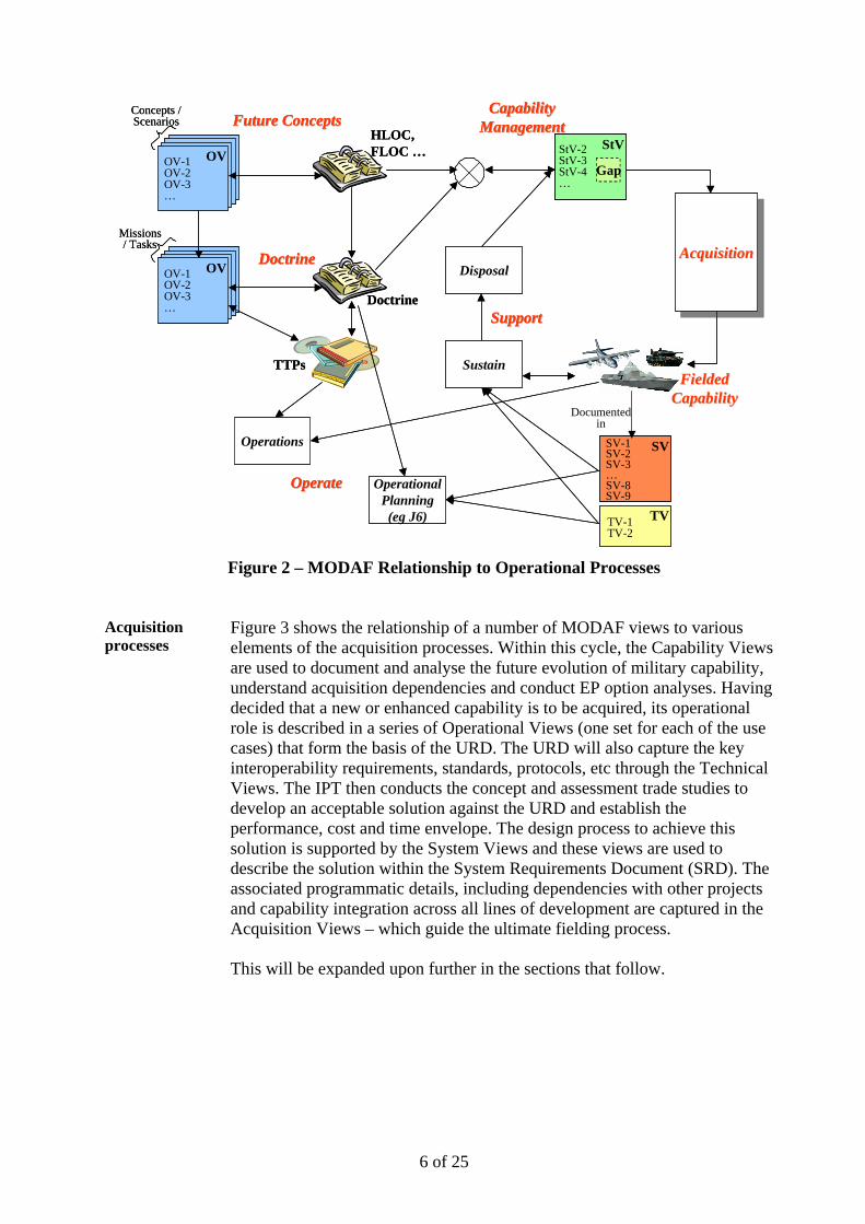
Figure 2 shows the relationship of a number of MODAF views to various elements of the operational processes. This includes the development of Operational Views to support the future concepts, doctrine and tactics, techniques and procedures. Through capability audit and / or comparison with future concepts capability gaps can be identified and documented in Strategic Views. These gaps will initiate future acquisition cycles, which ultimately lead to the fielding of new or enhanced military capability and its associated documentation (in System and Technical Views). This information regarding the fielded capability is used in supporting the capability. It also provides an input to the operational planning process along with operational information such as accepted doctrine. This will be expanded upon further in the sections that follow.
6 of 25
TVTV-1TV-2
TVTV-1TV-2
SVSV-1SV-2SV-3…SV-8SV-9
SVSV-1SV-2SV-3…SV-8SV-9
DoctrineDoctrineOVOV-1
OV-2OV-3… Doctrine
TTPs
Missions/ Tasks
DoctrineDoctrineOVOV-1
OV-2OV-3… Doctrine
TTPs
Missions/ Tasks
HLOC, FLOC …OV
Concepts / Scenarios
OV-1OV-2OV-3…
Future ConceptsFuture ConceptsHLOC, FLOC …OV
Concepts / Scenarios
OV-1OV-2OV-3…
Future ConceptsFuture Concepts
AcquisitionAcquisitionAcquisitionAcquisitionAcquisitionAcquisition
Documented in
CapabilityCapabilityManagementManagement
StVStV-2StV-3StV-4…
Gap
Disposal
CapabilityCapabilityManagementManagement
StVStV-2StV-3StV-4…
Gap
StVStV-2StV-3StV-4…
Gap
Disposal
Operational Planning (eg J6)
Operations
OperateOperate Operational Planning (eg J6)
Operations
OperateOperate
Sustain
SupportSupport
Sustain
SupportSupport
FieldedFieldedCapabilityCapability
Figure 2 – MODAF Relationship to Operational Processes
Acquisition processes
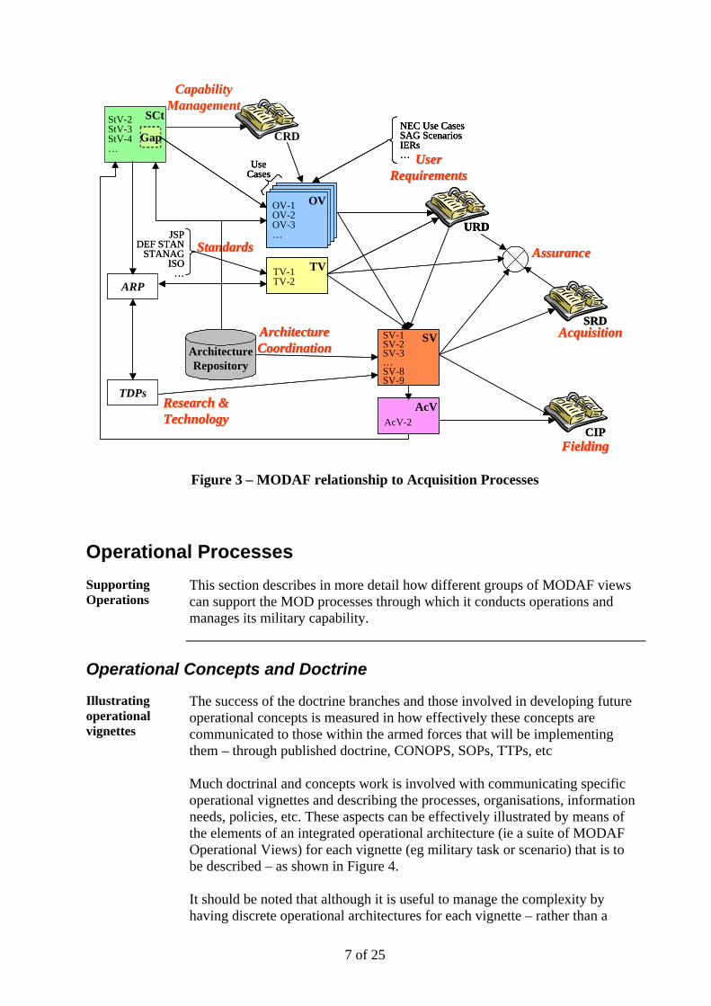
Figure 3 shows the relationship of a number of MODAF views to various elements of the acquisition processes. Within this cycle, the Capability Views are used to document and analyse the future evolution of military capability, understand acquisition dependencies and conduct EP option analyses. Having decided that a new or enhanced capability is to be acquired, its operational role is described in a series of Operational Views (one set for each of the use cases) that form the basis of the URD. The URD will also capture the key interoperability requirements, standards, protocols, etc through the Technical Views. The IPT then conducts the concept and assessment trade studies to develop an acceptable solution against the URD and establish the performance, cost and time envelope. The design process to achieve this solution is supported by the System Views and these views are used to describe the solution within the System Requirements Document (SRD). The associated programmatic details, including dependencies with other projects and capability integration across all lines of development are captured in the Acquisition Views – which guide the ultimate fielding process. This will be expanded upon further in the sections that follow.
7 of 25
CRD
SCtStV-2StV-3StV-4…
AssuranceAssuranceAssuranceAssuranceTVTV-1
TV-2
GapNEC Use CasesSAG ScenariosIERs…
OV
UseCases
OV-1OV-2OV-3…
URD
UserUserRequirementsRequirements
TVTV-1TV-2
TVTV-1TV-2
GapGapNEC Use CasesSAG ScenariosIERs…
NEC Use CasesSAG ScenariosIERs…
OV
UseCases
OV-1OV-2OV-3…
OV
UseCases
OV-1OV-2OV-3…
URDURD
UserUserRequirementsRequirements
ARP
TDPsResearch &Research &TechnologyTechnology
ARP
TDPsResearch &Research &TechnologyTechnology
CIPFieldingFielding
AcVAcV-2
CIPFieldingFielding
AcVAcV-2
SRDSVSV-1
SV-2SV-3…SV-8SV-9
AcquisitionAcquisitionSRD
SVSV-1SV-2SV-3…SV-8SV-9
AcquisitionAcquisition
CapabilityCapabilityManagementManagement
JSPDEF STAN
STANAGISO
…
StandardsStandardsJSP
DEF STANSTANAG
ISO…
StandardsStandards
ArchitectureRepository
ArchitectureArchitectureCoordinationCoordinationArchitecture
Repository
ArchitectureArchitectureCoordinationCoordination
Figure 3 – MODAF relationship to Acquisition Processes
Operational Processes
Supporting Operations
This section describes in more detail how different groups of MODAF views can support the MOD processes through which it conducts operations and manages its military capability.
Operational Concepts and Doctrine
Illustrating operational vignettes
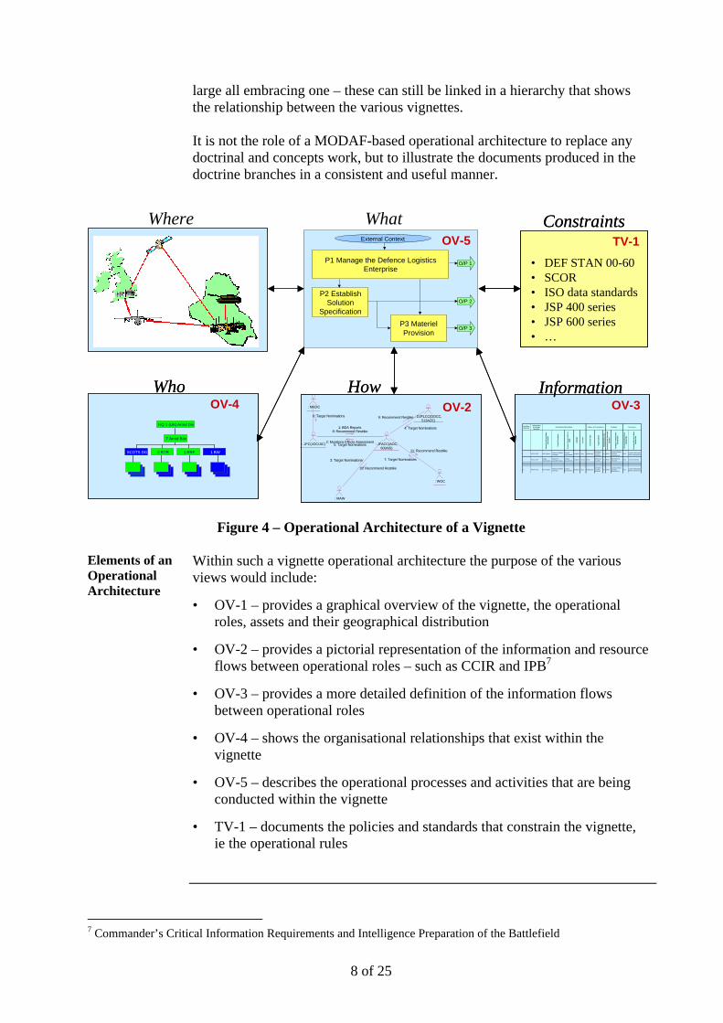
The success of the doctrine branches and those involved in developing future operational concepts is measured in how effectively these concepts are communicated to those within the armed forces that will be implementing them – through published doctrine, CONOPS, SOPs, TTPs, etc Much doctrinal and concepts work is involved with communicating specific operational vignettes and describing the processes, organisations, information needs, policies, etc. These aspects can be effectively illustrated by means of the elements of an integrated operational architecture (ie a suite of MODAF Operational Views) for each vignette (eg military task or scenario) that is to be described – as shown in Figure 4. It should be noted that although it is useful to manage the complexity by having discrete operational architectures for each vignette – rather than a
8 of 25
large all embracing one – these can still be linked in a hierarchy that shows the relationship between the various vignettes. It is not the role of a MODAF-based operational architecture to replace any doctrinal and concepts work, but to illustrate the documents produced in the doctrine branches in a consistent and useful manner.
Figure 4 – Operational Architecture of a Vignette Elements of an Operational Architecture
Within such a vignette operational architecture the purpose of the various views would include:
• OV-1 – provides a graphical overview of the vignette, the operational roles, assets and their geographical distribution
• OV-2 – provides a pictorial representation of the information and resource flows between operational roles – such as CCIR and IPB7
• OV-3 – provides a more detailed definition of the information flows between operational roles
• OV-4 – shows the organisational relationships that exist within the vignette
• OV-5 – describes the operational processes and activities that are being conducted within the vignette
• TV-1 – documents the policies and standards that constrain the vignette, ie the operational rules
7 Commander’s Critical Information Requirements and Intelligence Preparation of the Battlefield
P2 Establish Solution
Specification
P1 Manage the Defence Logistics Enterprise
External Context
O/P 1
O/P 2
O/P 3P3 Materiel Provision
OV-5
WhatOV-1
Where
Who
SCOTS DG 2 RTR 1 RRF 1 BW
7 Armd Bde
HQ 1 (UK) Armd Div
SCOTS DG 2 RTR 1 RRF 1 BW
7 Armd Bde
HQ 1 (UK) Armd Div
OV-4Who
SCOTS DG 2 RTR 1 RRF 1 BW
7 Armd Bde
HQ 1 (UK) Armd Div
SCOTS DG 2 RTR 1 RRF 1 BW
7 Armd Bde
HQ 1 (UK) Armd Div
OV-4Needline Identifier
Information Exchange Identifier
Info
rmat
ion
Ele
men
t Nam
e A
nd Id
entif
ier
Con
tent
Des
crip
tion
Mis
sion
/ S
cena
rio
UJT
L or
M
ETL
Lang
uage
Acc
urac
y
Tran
sact
ion
Type
Trig
gerin
g E
vent
Inte
rope
rabi
lity
Leve
l
Sen
ding
Op
Nod
e N
ame
And
Id
entif
ier
Sen
ding
Op
Act
ivity
Nam
e A
nd Id
entif
ier
Rec
eivi
ng O
p N
ode
Nam
e A
nd Id
entif
ier
Rec
eivi
ng O
p A
ctiv
ity N
ame
And
Iden
tifie
r
1 WOC-AOC BDA ReportReport on Battle Damage
Combat Assessment
English 1 Day collaborateAir Strike 072200, 0615am
2A WOCConduct Battle Damage Assessment
AOCConduct Munitions Effects Asessment
1 WOC-AOCTarget Nominations
Report on possible tragets
Combat Assessment
English 2 hours directAitTO XX, 072300
1B WOCRecommend Restrike
AOC External Activity
2…
11 MAW-AOC BDA ReportReport on Battle Damage
Combat Assessment
English 1 Day collaborateAir Strike 072200, 0615am
2A MAWConduct Battle Damage Assessment
AOCConduct Munitions Effects Asessment
Nature of TransactionInformation Description Producer Consumer
OV-3Information
Needline Identifier
Information Exchange Identifier
Info
rmat
ion
Ele
men
t Nam
e A
nd Id
entif
ier
Con
tent
Des
crip
tion
Mis
sion
/ S
cena
rio
UJT
L or
M
ETL
Lang
uage
Acc
urac
y
Tran
sact
ion
Type
Trig
gerin
g E
vent
Inte
rope
rabi
lity
Leve
l
Sen
ding
Op
Nod
e N
ame
And
Id
entif
ier
Sen
ding
Op
Act
ivity
Nam
e A
nd Id
entif
ier
Rec
eivi
ng O
p N
ode
Nam
e A
nd Id
entif
ier
Rec
eivi
ng O
p A
ctiv
ity N
ame
And
Iden
tifie
r
1 WOC-AOC BDA ReportReport on Battle Damage
Combat Assessment
English 1 Day collaborateAir Strike 072200, 0615am
2A WOCConduct Battle Damage Assessment
AOCConduct Munitions Effects Asessment
1 WOC-AOCTarget Nominations
Report on possible tragets
Combat Assessment
English 2 hours directAitTO XX, 072300
1B WOCRecommend Restrike
AOC External Activity
2…
11 MAW-AOC BDA ReportReport on Battle Damage
Combat Assessment
English 1 Day collaborateAir Strike 072200, 0615am
2A MAWConduct Battle Damage Assessment
AOCConduct Munitions Effects Asessment
Nature of TransactionInformation Description Producer Consumer
OV-3Information
OV-2 : NMJIC
: JFC(JOC/JIC) : JFACC(AOC, 609AIS)
: DJFLCC(DOCC, 513ACE)
: MAW
: WOC
6: Target Nominations
1: BDA Reports8: Recommend Restrike
2: Munitions Effects Assessment5: Target Nominations
4: Target Nominations
9: Recommend Restrike
3: Target Nominations
10: Recommend Restrike
7: Target Nominations
11: Recommend Restrike
HowOV-2 : NMJIC
: JFC(JOC/JIC) : JFACC(AOC, 609AIS)
: DJFLCC(DOCC, 513ACE)
: MAW
: WOC
6: Target Nominations
1: BDA Reports8: Recommend Restrike
2: Munitions Effects Assessment5: Target Nominations
4: Target Nominations
9: Recommend Restrike
3: Target Nominations
10: Recommend Restrike
7: Target Nominations
11: Recommend Restrike
How
TV-1
Constraints
• DEF STAN 00-60• SCOR• ISO data standards• JSP 400 series• JSP 600 series• …
TV-1
Constraints
• DEF STAN 00-60• SCOR• ISO data standards• JSP 400 series• JSP 600 series• …
9 of 25
Providing consistency
The use of a MODAF operational architecture provides consistency to the operational vignettes in a number of ways:
• All operational vignettes will be portrayed in a uniform manner (ie the same set of OVs)
• A linked operational architecture includes a number of cross-checks between the views that will ensure that there is consistency within the different views of the vignette
• Operational concepts and doctrine provide important inputs to the capability management process by defining the strategic capability vision (StV-1) and defining the capability functions that need to be fulfilled (StV-2)
Operational Planning
Understanding the military capability options
When the fielded military capability is adequately documented in System Views and Technical Views this will provide a rich source of information to those conducting operational planning, such as the selection of military capability options within J3 and planning communication networks within J6 and DCSA prior to an operation. How MODAF architectures may support these planning processes is explained below:
• From an analysis of the military strategic objectives the military tasks that are required will be developed in consultation with the published doctrine and supporting operational architectures (see above)
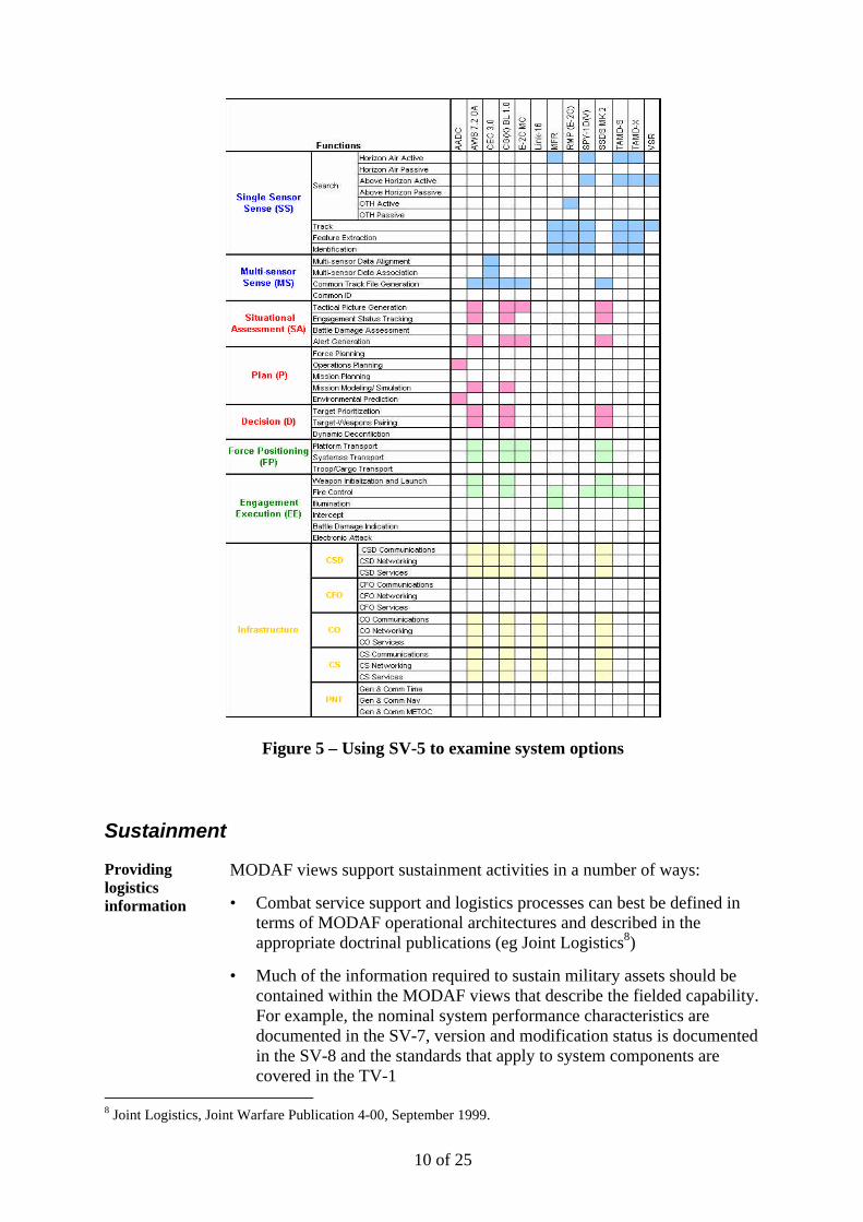
• Once the operational functions that will be needed are known, the systems that are available to support these can be identified through the use of the SV-5 views (see example in Figure 5 below, courtesy of US Navy)
• This analysis should provide a number of system options – the interoperability of which should be explored through the use appropriate System Views (eg SV-1 and SV-3) and Technical Views which describe the standards and protocols to which the systems comply
• The network configurations required to support these system options can be explored through the use of the SV-2 (network connectivity) and TV-1 (standards profile) views
• If required, executable models of the resulting system architecture options can be produced that assess their relative performance against key military effectiveness measures such as reach, tempo and collateral damage
10 of 25
Figure 5 – Using SV-5 to examine system options
Sustainment
Providing logistics information
MODAF views support sustainment activities in a number of ways:
• Combat service support and logistics processes can best be defined in terms of MODAF operational architectures and described in the appropriate doctrinal publications (eg Joint Logistics8)
• Much of the information required to sustain military assets should be contained within the MODAF views that describe the fielded capability. For example, the nominal system performance characteristics are documented in the SV-7, version and modification status is documented in the SV-8 and the standards that apply to system components are covered in the TV-1
8 Joint Logistics, Joint Warfare Publication 4-00, September 1999.
11 of 25
• The planning for part obsolescence or provision of redundancy in case of failures can be supported by an understanding of the specified system / component functionality (SV-4), interfaces (SV-1) and operational functions that it supports (SV-5)
• The retirement and disposal of military assets needs to be co-ordinated with their planned replacement – which is achieved through the feedback loop from the sustainment community to the capability management processes, through the Strategic Views (see below)
Capability Management
Supporting capability mapping and gap analysis
The Strategic Views9 within MODAF are in addition to the standard DODAF views and have been tailored to the needs of the MOD capability management processes that are conducted within the Equipment Capability Customer (ECC). Specifically the StVs provide a readily assimilated capability map, highlight the issues within a capability area and support all of the necessary capability analysis activities such as capability audit and options analysis.
Doctrinally-based
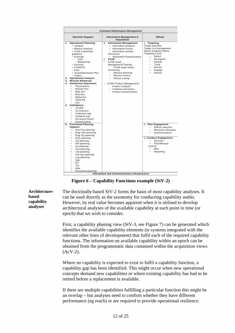
The StVs are firmly rooted in a doctrinal base. The starting point for capability analysis is an understanding of the MOD strategic capability vision – which is captured as StV-1. Examples of inputs into this would include the HLOC10 and NEC Concept11. This may differ significantly from current doctrine and the ability of the existing capability. The capability needs obtained from doctrine and strategic capability vision are decomposed into capability functions which are documented in the StV-2, an example of which is shown at Figure 6. These doctrinally based capability functions then form the basis for a variety of capability models and analyses.
9 Overview of Strategic Views, MODAF-M04-001, September 2004. 10 The UK Joint High Level Operational Concept, JDCC, October 2003. 11 NEC Outline Concept, DSTL, May 2003.
12 of 25
Command Battlespace Management
Decision Support Information Management &Acquisition
Effects
1. Operational Planning:• Initiation• Mission Analysis• CCIR & planningguidance• Estimate
- COA - Wargaming
• Decision• CONOPS• SoM• Assemble/review Plan• Orders
2. Operational Analysis3. Mission Rehearsal4. Situational Awareness:
• Physical Env• Mission Env• Blue Env• Red Env• White Env• APNLRS• CID
5. Intelligence:• CCIRM• Int Direction• Collection mgt• Collation mgt• All-source fusion• Dissemination
1. Targeting:Target selectionTarget List managementAttack Guidance MatrixTargeting Cycle:
• Detect• Recognise• Identify• Track• Decide• Engage• Assess
2. Plan Engagement:• Effects selection• Resource allocation• Synchronisation
6. Functional PlanningSupport:
• Arty Fire planning• Engr Obs planning• Engr Sp planning• EOD planning• AD planning• EW planning• Air planning• Avn planning• CIS planning• Info ops planning• Log planning• Sup• ES• Tpt• Med• Personnel planning
1. Information Management• Information Analysis• Information Fusion• Information Quality
Assurance• Information Dissemination
2. STAR• STAR Asset
Management/Tasking:− STAR asset status
monitoring− Mission planning− Mission control− Sensor cueing
• STAR Product Management:− Product analysis− Collation and fusion− Product Dissemination
3. Conduct Engagement:• Decision• Fires/Mission
Control• BDA• Reporting
Information and Communications Infrastructure
Figure 6 – Capability Functions example (StV-2) Architecture-based capability analyses
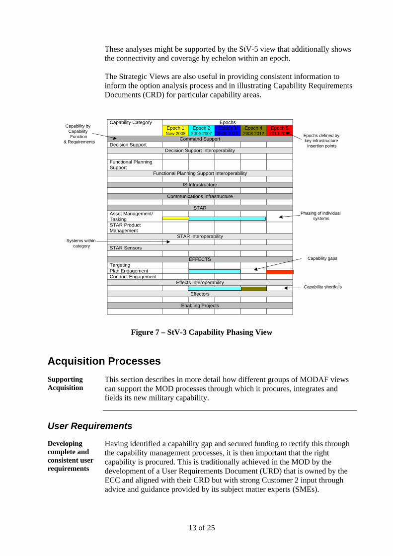
The doctrinally-based StV-2 forms the basis of most capability analyses. It can be used directly as the taxonomy for conducting capability audits. However, its real value becomes apparent when it is utilised to develop architectural analyses of the available capability at each point in time (or epoch) that we wish to consider. First, a capability phasing view (StV-3, see Figure 7) can be generated which identifies the available capability elements (ie systems integrated with the relevant other lines of development) that fulfil each of the required capability functions. The information on available capability within an epoch can be obtained from the programmatic data contained within the acquisition views (AcV-2). Where no capability is expected to exist to fulfil a capability function, a capability gap has been identified. This might occur when new operational concepts demand new capabilities or where existing capability has had to be retired before a replacement is available. If there are multiple capabilities fulfilling a particular function this might be an overlap – but analyses need to confirm whether they have different performance (eg reach) or are required to provide operational resilience.
13 of 25
These analyses might be supported by the StV-5 view that additionally shows the connectivity and coverage by echelon within an epoch. The Strategic Views are also useful in providing consistent information to inform the option analysis process and in illustrating Capability Requirements Documents (CRD) for particular capability areas.
Systems within category
Capability by Capability Function
& Requirements
Phasing of individual systems
Capability gaps
Capability shortfalls
EpochsCapability CategoryEpoch 1Now-2008
Epoch 22004-2007
Epoch 32006-2011
Epoch 42008-2012
Epoch 52010-2017
Command SupportDecision Support
Decision Support Interoperability
Functional PlanningSupport
Functional Planning Support Interoperability
IS Infrastructure
Communications Infrastructure
STARAsset Management/TaskingSTAR ProductManagement
STAR Interoperability
STAR Sensors
EFFECTSTargetingPlan EngagementConduct Engagement
Effects Interoperability
Effectors
Enabling Projects
Epochs defined by key infrastructure
insertion points
Figure 7 – StV-3 Capability Phasing View
Acquisition Processes
Supporting Acquisition
This section describes in more detail how different groups of MODAF views can support the MOD processes through which it procures, integrates and fields its new military capability.
User Requirements
Developing complete and consistent user requirements
Having identified a capability gap and secured funding to rectify this through the capability management processes, it is then important that the right capability is procured. This is traditionally achieved in the MOD by the development of a User Requirements Document (URD) that is owned by the ECC and aligned with their CRD but with strong Customer 2 input through advice and guidance provided by its subject matter experts (SMEs).
14 of 25
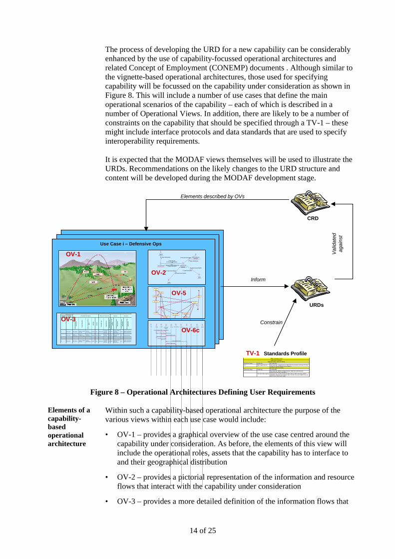
The process of developing the URD for a new capability can be considerably enhanced by the use of capability-focussed operational architectures and related Concept of Employment (CONEMP) documents . Although similar to the vignette-based operational architectures, those used for specifying capability will be focussed on the capability under consideration as shown in Figure 8. This will include a number of use cases that define the main operational scenarios of the capability – each of which is described in a number of Operational Views. In addition, there are likely to be a number of constraints on the capability that should be specified through a TV-1 – these might include interface protocols and data standards that are used to specify interoperability requirements. It is expected that the MODAF views themselves will be used to illustrate the URDs. Recommendations on the likely changes to the URD structure and content will be developed during the MODAF development stage.
Use Case i – Defensive Ops
CRD
URDs
Inform
Elements described by OVs
Val
idat
ed
agai
nst
OV-2
: NMJIC
: JFC(JOC/JIC) : JFACC(AOC, 609AIS)
: DJFLCC(DOCC, 513ACE)
: MAW
: WOC
6: Target Nominations
1: BDA Reports8: Recommend Restrike
2: Munitions Effects Assessment5: Target Nominations
4: Target Nominations
9: Recommend Restrike
3: Target Nominations
10: Recommend Restrike
7: Target Nominations
11: Recommend Restrike
Needline Identifier
Information Exchange Identifier
Info
rmat
ion
Ele
men
t Nam
e A
nd Id
entif
ier
Con
tent
Des
crip
tion
Mis
sion
/ S
cena
rio
UJT
L or
M
ETL
Lang
uage
Acc
urac
y
Tran
sact
ion
Type
Trig
gerin
g E
vent
Inte
rope
rabi
lity
Leve
l
Sen
ding
Op
Nod
e N
ame
And
Id
entif
ier
Sen
ding
Op
Act
ivity
Nam
e A
nd Id
entif
ier
Rec
eivi
ng O
p N
ode
Nam
e A
nd Id
entif
ier
Rec
eivi
ng O
p A
ctiv
ity N
ame
And
Iden
tifie
r
1 WOC-AOC BDA Report Report on Battle Damage
Combat Assessment English 1 Day collaborate
Air Strike 072200, 0615am
2A WOCConduct Battle Damage Assessment
AOC Conduct Munitions Effects Asessment
1 WOC-AOC Target Nominations
Report on possible tragets
Combat Assessment English 2 hours direct AitTO XX,
072300 1B WOC Recommend Restrike AOC External Activity
2…
11 MAW-AOC BDA Report Report on Battle Damage
Combat Assessment English 1 Day collaborate
Air Strike 072200, 0615am
2A MAWConduct Battle Damage Assessment
AOC Conduct Munitions Effects Asessment
Nature of TransactionInformation Description Producer Consumer
OV-3ConductSR
Send SR Data
Send Target Nominations
Produce/Send BDA Reoprts
Conduct Battle Damage Assessment
Assess Enemy Force Effectiveness
Conduct Munitions Effects Assessment
Send Collection Requirements
Obtain New Col lect ions
Start Activities
Receive BDA Reports
AnalysisRecommend Restr ikeMunit ions Ef fects AssessmentBatt le Damage Assessment
OV-5
ConductSR
Send SR Data
Send Target Nominations
Produce/Send BDA Reoprts
Conduct Battle Damage Assessment
Assess Enemy Force Effectiveness
Conduct Munitions Effects Assessment
Send Collection Requirements
Obtain New Col lect ions
Start Activities
Receive BDA Reports
AnalysisRecommend Restr ikeMunit ions Ef fects AssessmentBatt le Damage Assessment
OV-5
: DIA : MAW : WOC : JFACC(AOC, 609AIS)
: JFC(JOC/JIC) : DCCC : JFSOCC : DJFLCC(D...
: F2C2 : JFMCC : NMJIC
Imagery, MISREPs, WSV, Combat Reports
Imagery, MISREPs, WSV, Combat Reports
Target Materials Analysis
Target Materials Analysis
Target Materials Analysis
Collection Requirements
Collection Requirements
OV-6c : DIA : MAW : WOC : JFACC(AOC,
609AIS)
: JFC(JOC/JIC) : DCCC : JFSOCC : DJFLCC(D...
: F2C2 : JFMCC : NMJIC
Imagery, MISREPs, WSV, Combat Reports
Imagery, MISREPs, WSV, Combat Reports
Target Materials Analysis
Target Materials Analysis
Target Materials Analysis
Collection Requirements
Collection Requirements
OV-6c
OV-1
TV-1 Standards ProfileTRM’s Interfaces View
Application Software
MISSION AREA APPLICATIONS
SERVICE AREA SERVICE STANDARD
All Web Applications Interface 4D: (Application to Web Server) Common Gateway Interface (CGI) 1.1, NCSA Software Development
SUPPORT APPLICATIONS
SERVICE AREA SERVICE STANDARD
Interface 4L: HTML 4.0 Specif ication, W3C Recommendation (Hypertext Markup Language)
Personal Messaging Interface 4D: (E-Mail Client to E-Mail Server) IETF Standard 10/RFC -821/RFC -1869/RFC-1870 Simple Mail Transfer Protoco l (SMTP) Service Extensions, November 1995
Constrain
Figure 8 – Operational Architectures Defining User Requirements Elements of a capability-based operational architecture
Within such a capability-based operational architecture the purpose of the various views within each use case would include:
• OV-1 – provides a graphical overview of the use case centred around the capability under consideration. As before, the elements of this view will include the operational roles, assets that the capability has to interface to and their geographical distribution
• OV-2 – provides a pictorial representation of the information and resource flows that interact with the capability under consideration
• OV-3 – provides a more detailed definition of the information flows that

15 of 25
interact with the capability under consideration
• OV-5 – describe the operational processes and activities that are utilised within the use case under consideration
• OV-6 – describes the operational rules and logic that apply
• TV-1 – documents the policies and standards that constrain the operational capability – including the interface standards and data format required to achieve interoperability
System Design and Delivery
Demonstrating a coherent and compliant system design
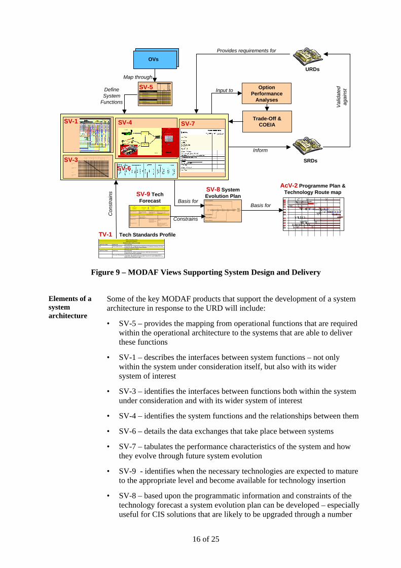
Based upon the URD specified by the ECC, the IPT and its industrial contractor(s) commence the system design process. A key element of this that is required prior to a successful Main Gate is the development of a sufficiently detailed and complete System Requirements Document (SRD). A good SRD should capture the intent of the system design, describe its interfaces and detail the system evolution plan. It should also be possible to validate that the design captured in the SRD satisfies the requirement of the URD. Functional and physical architectures of the system captured in MODAF provide a sound mechanism for documenting the system design and capturing the details necessary for a sound SRD. An overview of how a MODAF-based architecture can support the system design and delivery process is shown in Figure 8. This shows the pivotal role of the SV-5 in defining the mapping between the operational functions specified in the OVs through to system functions developed in the SVs. A suite of MODAF System Views provide a comprehensive and integrated definition of the system under consideration. The main System Views required to achieve this are likely to include the system functions (SV-4), system interfaces (SV-3), interconnection diagram (SV-1), data exchange format (SV-6) and system performance (SV-7). The whole system design must be constrained according to the standards and policy documented in the TV-1. It is expected that these MODAF views themselves will be used to illustrate the SRDs. Recommendations on the likely changes to the SRD structure and content will be developed during the MODAF development stage.
MODAF views assist programme planning
Figure 9 also shows the ability of the MODAF views to support not only the system design cycle, but also technology insertion planning, system evolution planning and acquisition planning. For example, the technology forecast (SV-9) will help define technology insertion points that drive the system evolution (SV-8) and hence the overall programme plan (AcV-2).
16 of 25
Operational Activities Assess
Col
lect
Exp
loit
Dec
ide
TC
T N
egat
ion
- P
air
Wea
pon/
Pltf
m/S
nsr
to
Tar
get
Strike
Rem
ove
from
Tar
get
List
Col
lect
Exp
loit
Dec
ide
TC
T N
egat
ion
- P
air
Wea
pon/
Pltf
m/S
nsr
to
Tar
get
SF# System Functions - 3.0 (Act) 2.2.
1
2.2.
3
2.2.
3.1
2.2.
3.4
2.3
2.4
2.4.
1
2.4.
2
2.4.
3
2.4.
4.4
2.4.
5.5
2.4.
6
3.1.
1
3.1.
5
5.1.
1.1
5.3
3.1 Engagement Execution3.1.1 Direct Attack/Evasive Maneuvers X X3.1.2 Determine Engageability X X3.1.2.1 Develop Intercept Prediction X X3.2 Target Development3.2.1 Employ Targeting Assets X X3.2.1.1 Task/Re-task Targeting Assets X X3.2.1.1.1 Transmit Tasking and Target Data to Targeting Assets X X X X3.2.2 Designate Target X X3.2.4.1 Determine Target Location X X X X X XHA# Human Activities - 3.0 (Act)
3.1 Assess ISR Cue3.1.1 Determine if cue qualifies as TCT X3.1.2 Determine time latency of cueing X X3.1.3 Compare IMINT cue characteristics against known IMINT data X3.3.4 Compare SIGINT cue characteristics against known SIGINT data X
URDs
SV-5
Map through
SV-1
Define System
Functions
SRDs
Inform
Val
idat
ed
agai
nst
SV-8 System Evolution PlanSV-9 Tech
Forecast
Option Performance
Analyses
Trade-Off & COEIA
Input to
,2& )2&
:DWFKNHHSHU
2FW 'HF
51&66
%/'&66,)/3'5
)DOFRQ,QFUHPHQW$
0DLQ*DWH,QF$,QLWLDO*DWH,QF%,QF$'0&WW/HW
)LHOG7ULDOV'HOLYHU7UDQFKH 'HOLYHU7UDQFKH 'HOLYHU7UDQFKH,QF$,6'
,QF$,6'0DLQ*DWH,QF%
'HOLYHU7UDQFKH
'HOLYHU7UDQFKH'HOLYHU7UDQFKH
)DOFRQ,QFUHPHQW%
'0&WW/HW
)DOFRQ,QFUHPHQW&
,QLWLDO*DWH,QF&
)LHOG7ULDOV,QF%'HOLYHU7UDQFKH'HOLYHU7UDQFKH'HOLYHU7UDQFKH'HOLYHU7UDQFKH'HOLYHU7UDQFKH'HOLYHU7UDQFKH
'HOLYHU57768SJUDGH
'HOLYHU7UDQFKH 'HOLYHU7UDQFKH
'HOLYHU7UDQFKH
7HFKQRORJ \UHIUHVKHV
&RUPRUDQW
0D\,6'
0D\)2&
2FW)2&
'HF,6'
0D\06$0
-DQ06$0
2FW 'HF0DU9HUVLRQ
'HF9HUVLRQ
0HUJHG&66-2&6"-2&6
&RPPRQ2SHUDWLRQDO&RPPDQG6XSSRUW6\VWHP"
6HS,QF%$VVHVV3KDVH&WW/HW
$6725
2S7ULDOVDF*6 2S7ULDOVDF*6 %$786WULDO,6'/LP&5
,2&)XOO&5&WWRULQWHJWULDOV
-&6/RJ
3KDVH,QF3KDVH,QF
,2&
)2&)2&
',,
0DLQ*DWH ,6' )2&
%2:0$1
&,3
5$)&&,6
,6' /LWWRUDO25'$025'
(&,32)7 ,&,3WR',/ )&,3WR',/)&%,6$,2&
6WDJH 6WDJH
"
)XOO)&%,6$
/DQG25'%RZPDQ,2& %RZPDQ,6'&DSDELOLW\25'&DSDELOLW\%GH2)7
,2& )2&
:DWFKNHHSHU
2FW 'HF
51&66
,2& )2&
:DWFKNHHSHU
2FW 'HF
51&66
%/'&66,)/3'5
)DOFRQ,QFUHPHQW$
0DLQ*DWH,QF$,QLWLDO*DWH,QF%,QF$'0&WW/HW
)LHOG7ULDOV'HOLYHU7UDQFKH 'HOLYHU7UDQFKH 'HOLYHU7UDQFKH,QF$,6'
,QF$,6'0DLQ*DWH,QF%
'HOLYHU7UDQFKH
'HOLYHU7UDQFKH'HOLYHU7UDQFKH
%/'&66,)/3'5
)DOFRQ,QFUHPHQW$
0DLQ*DWH,QF$,QLWLDO*DWH,QF%,QF$'0&WW/HW
)LHOG7ULDOV'HOLYHU7UDQFKH 'HOLYHU7UDQFKH 'HOLYHU7UDQFKH,QF$,6'
,QF$,6'0DLQ*DWH,QF%
'HOLYHU7UDQFKH
'HOLYHU7UDQFKH'HOLYHU7UDQFKH
)DOFRQ,QFUHPHQW%
'0&WW/HW
)DOFRQ,QFUHPHQW&
,QLWLDO*DWH,QF&
)LHOG7ULDOV,QF%'HOLYHU7UDQFKH'HOLYHU7UDQFKH'HOLYHU7UDQFKH'HOLYHU7UDQFKH'HOLYHU7UDQFKH'HOLYHU7UDQFKH
'HOLYHU57768SJUDGH
'HOLYHU7UDQFKH 'HOLYHU7UDQFKH
'HOLYHU7UDQFKH
)DOFRQ,QFUHPHQW%
'0&WW/HW
)DOFRQ,QFUHPHQW&
,QLWLDO*DWH,QF&
)LHOG7ULDOV,QF%'HOLYHU7UDQFKH'HOLYHU7UDQFKH'HOLYHU7UDQFKH'HOLYHU7UDQFKH'HOLYHU7UDQFKH'HOLYHU7UDQFKH
'HOLYHU57768SJUDGH
'HOLYHU7UDQFKH 'HOLYHU7UDQFKH
'HOLYHU7UDQFKH
7HFKQRORJ \UHIUHVKHV
&RUPRUDQW
0D\,6'
0D\)2&
2FW)2&
'HF,6'
0D\06$0
-DQ06$0
2FW 'HF0DU9HUVLRQ
'HF9HUVLRQ
0HUJHG&66-2&6"-2&6
&RPPRQ2SHUDWLRQDO&RPPDQG6XSSRUW6\VWHP"
6HS,QF%$VVHVV3KDVH&WW/HW
7HFKQRORJ \UHIUHVKHV
&RUPRUDQW
0D\,6'
0D\)2&
2FW)2&
'HF,6'
0D\06$0
-DQ06$0
2FW 'HF0DU9HUVLRQ
'HF9HUVLRQ
0HUJHG&66-2&6"-2&6
&RPPRQ2SHUDWLRQDO&RPPDQG6XSSRUW6\VWHP"
6HS,QF%$VVHVV3KDVH&WW/HW
$6725
2S7ULDOVDF*6 2S7ULDOVDF*6 %$786WULDO,6'/LP&5
,2&)XOO&5&WWRULQWHJWULDOV
-&6/RJ
3KDVH,QF3KDVH,QF
,2&
)2&
$6725
2S7ULDOVDF*6 2S7ULDOVDF*6 %$786WULDO,6'/LP&5
,2&)XOO&5&WWRULQWHJWULDOV
-&6/RJ
3KDVH,QF3KDVH,QF
,2&
)2&)2&
',,
0DLQ*DWH ,6' )2&
%2:0$1
)2&
',,
0DLQ*DWH ,6' )2&
%2:0$1
&,3
5$)&&,6
,6' /LWWRUDO25'$025'
(&,32)7 ,&,3WR',/ )&,3WR',/)&%,6$,2&
6WDJH 6WDJH
"
)XOO)&%,6$
/DQG25'%RZPDQ,2& %RZPDQ,6'&DSDELOLW\25'&DSDELOLW\
&,3
5$)&&,6
,6' /LWWRUDO25'$025'
(&,32)7 ,&,3WR',/ )&,3WR',/)&%,6$,2&
6WDJH 6WDJH
"
)XOO)&%,6$
/DQG25'%RZPDQ,2& %RZPDQ,6'&DSDELOLW\25'&DSDELOLW\%GH2)7
AcV-2 Programme Plan & Technology Route map
TV-1 Tech Standards Profile
Con
stra
ins
Basis for
Constrains
Basis for+ 1 yr + 3 yrs + 5 yrs + 7 yrs + 10 yrs
V 0.1 V 0.2 V 1.0 V 1.5 V 2.0
RobustAdaptive DistributedSystem
StovepipeLegacySystems
Block II Upgrades
Phase I, Version 2
Block I Upgrades
Phase I Integration
Phase II Integration
TECHNOLOGY FORECASTS TRM
TECHNOLOGY
CATEG ORY
SHORT TERM
(1 year)
MID TERM
(3 years)
LONG TERM
(5 years)
Application Software
Support Applications Microsoft Office 2000 available (for Windows 2000)
Microsoft Office 2000 stable enough for full scale implementation
Microsoft Office available for Linux
E-mail on wireless PDAs commonplace
Application Platform
Data Management Oracle 9i available
MySQL (Open Source DBMS) available
Operating System Next MS Windows desktop upgrade expected
Next Red Hat Linux major release expected
Next MS Windows server upgrade expected
Physical Environment Intel IA-64 becomes standard processor for desktops
Initial use of quantum computing technologies
SV-6
arm ig an
ALCON
OWMAN
ORMORANT
KYNET5
P IP CB ISA
BCB ISA
DBRIC
AKFAS T
S1( AP3 )
S 1( GP 3)
S1(QP2 4)
ACYS IS
NCS S
AFCC IS
CS
RRCC 2IS
I I S 1(AT acCS)
AH6 4
SL og
OOTHSAYER
STOR
ATCHKE EPER
OBRA
AMBA
RAP( L in kS ystem s)
AST
S GD
GO s
vi l ian
C o m m s S y s t e m s P t a r m i g a n Y Y ? Y Y Y Y Y ? ? ? ? Y ?F A L C O N Y Y Y Y Y ? ? ? Y Y Y ? ? Y ? ? ? ? ? ? ?B O W M A N Y Y Y Y Y Y Y Y Y Y Y Y Y Y Y Y ? Y Y Y Y ? Y Y Y Y YC O R M O R A N T Y Y Y Y Y ? Y Y Y Y Y ? ? ? Y Y ?S K Y N E T 5 ? Y Y Y ? ? Y Y Y Y Y ? ?
I n f r a s t r u c t u r e CIP Y Y Y Y Y Y Y Y Y Y Y Y Y Y ? Y ? Y Y Y Y ? ? Y Y YM I P Y Y Y Y Y Y Y ? ? ? ? ? ? ? ? ? ?
B I S A s F C B I S A Y Y Y Y Y Y Y Y ? ? Y Y YN B C B I S A Y Y Y Y Y Y Y ? ? ? ? ?A D B R I C Y Y Y Y Y Y Y ? ? ? ? ? ? ? ?M A K F A S T Y Y Y Y Y Y Y ? ? ? ?D S 1 ( A P 3 ) Y Y Y YD S 1 ( G P 3 ) Y Y Y YD S 1 ( Q P 2 4 ) Y Y Y YT A C Y S I S ? Y Y Y Y Y Y Y
C o m m a n d S u p p o r tS y s t e m s
R N C S S Y Y Y Y Y ? Y ? ? ? Y Y ? Y ?
R A F C C I S Y Y Y Y Y ? ? ? ? Y Y ? Y ? ? ?J O C S ? Y Y Y Y ? ? ? ? Y Y ? YA R R C C 2 I S ? ? Y Y Y Y ? ? ? ? ? ? ? ? ? ? ? ? Y ? ?D I I ? ? Y Y Y Y Y Y Y ?D S 1 ( A T a c C S ) Y Y ? Y Y Y YW A H 6 4J C S L o g ? ? ? ? ? ? ? ?
S e n s o r s S O O T H S A Y E R ? Y ? Y Y ? ? ? ? ?A S T O R ? Y Y ? Y Y ? ? ? ? ? ? ? ?W A T C H K E E P E R ? Y Y Y Y ? ? ? ? ? ? ? ?C O B R A ? ? Y Y ? ? ? ? ?M A M B A ? ? ? ? ? ? ? ?G R A P ( L i n k S y s t e m s ) ? ? ? ? ? ? ? ?
T r a i n i n g S y s t e m s C A S T Y YT E S Y Y
O t h e r s O G D Y Y YN G O s Y Y YCil i l ian Y Y Y
SV-3
SV-7
TRM’s Interfaces View
Application Software
MISSION AREA APPLICATIONS
SERVICE AREA SERVICE STANDARD
All Web Applications Interface 4D: (Application to Web Server) Common Gateway Interface (CGI) 1.1, NCSA Software Development
SUPPORT APPLICATIONS
S E RVICE AREA SERVICE STANDARD
Interface 4L: HTML 4.0 Specif ication, W3C Recommendation (Hypertext Markup Language)
Personal Messaging Interface 4D: (E-Mail Client to E-Mail Server) IETF Standard 10/RFC -821/RFC-1869/RFC-1870 Simple Mail Transfer Protocol (SMTP) Service Extensions, November 1995
OVs
Provides requirements for
SV-4
Figure 9 – MODAF Views Supporting System Design and Delivery
Elements of a system architecture
Some of the key MODAF products that support the development of a system architecture in response to the URD will include:
• SV-5 – provides the mapping from operational functions that are required within the operational architecture to the systems that are able to deliver these functions
• SV-1 – describes the interfaces between system functions – not only within the system under consideration itself, but also with its wider system of interest
• SV-3 – identifies the interfaces between functions both within the system under consideration and with its wider system of interest
• SV-4 – identifies the system functions and the relationships between them
• SV-6 – details the data exchanges that take place between systems
• SV-7 – tabulates the performance characteristics of the system and how they evolve through future system evolution
• SV-9 - identifies when the necessary technologies are expected to mature to the appropriate level and become available for technology insertion
• SV-8 – based upon the programmatic information and constraints of the technology forecast a system evolution plan can be developed – especially useful for CIS solutions that are likely to be upgraded through a number
17 of 25
of increments
• TV-1 – documents the policies and standards that constrain the system design– including the interface standards and data format required to achieve interoperability
• AcV-2 – documents the programme plan including dependencies (both inwards and outwards from the system under consideration) and key deliverables from the other lines of development
Capability Integration
Ensuring integration across all lines of development
An integrated architecture such as that offered by MODAF provides an enhanced degree of assurance that all of the necessary dependencies associated with fielding a particular capability have been considered. Some aspects of MODAF that help ensure this integration include:
• Basing the URD on integrated operational architectures that depict likely use cases for the capability including identification of the doctrinal constraints, organisational relationships, operational processes and interoperability requirements
• Explicit consideration of the appropriate policies, standards, protocols, etc through the TV-1 from early in the design cycle
• Use of an integrated programme plan showing not only dependencies with other systems but also across all lines of development
Taken together, these measures should ensure that there are fewer surprises during the acquisition cycle, hence less rework, better adherence to the PCT targets and ultimately the ability to deliver more capability for a certain EP budget.
Acquisition Support Activities
Integrating research and technology efforts
There are several key points within the MODAF architecture where important inputs from research and technology programmes can influence the acquisition cycle:
• Documenting how the doctrine, policy and standards that constrain the acquisition cycle are likely to evolve through time (TV-2). Such an approach would, for instance, have highlighted the importance of the emerging IPv6 and PKI standards and the need for the MOD to develop capability strategies that respond to these
• Understanding the technology forecast (SV-9) so that appropriate technology insertion points can be developed for acquisition programmes that ensure the required technologies have attained an appropriate Technology Readiness Level to minimise the risk to the acquisition programme
18 of 25
Architectural co-ordination ensures better coherence
At present there are few authoritative sources of information regarding operational or system architectures. As a consequence many teams have to commence their work with a metaphorical blank sheet of paper and often go about developing products which already exist, at least in part. An example of such nugatory work is the time and effort invested by every IPT early in the CADMID cycle to develop a clear understanding of its capability’s context and the systems with which it interfaces – much of which already exists from other IPT’s efforts. In other instances, relevant previous architectural products are known of, but due to interoperability issues between architectural tools cannot be re-used and have to be reconstructed or transcribed. In conjunction with MODAF the Integration Authority is developing a number of architectural services that will be of considerable benefit to MODAF users:
• A tool certification process to document which of the available architectural tools comply with MODAF
• A tool interoperability schema that will ensure that MODAF products can be exchanged between compliant tools
• An architectural repository that is used to store MODAF products for query and re-use by other teams
Enabling better governance and assurance
It is expected that MODAF products can play a useful role in informing governance and assurance processes that occur throughout the acquisition lifecycle (eg Initial and Main Gates, IOCA and release assurance). In addition to simply checking that an IPT has followed the appropriate process and produced the required architectural products, suitably trained scrutineers can assess the completeness of the resulting architectures and use them to assess the degree of risk remaining in areas such as interoperability.
Recommendations
Commencing MODAF architectures
It is recommended that the MOD COIs described within this paper start piloting the use of MODAF as described on activities which are being started from this time onwards. The MODAF project is encouraging pilot activities, reviewing lessons learned from early implementations and is able to offer support and guidance to some pilots. Although full MODAF documentation will not be available until the completion of the development stage, differing degrees of guidance are available through:
• DODAF handbooks document the existing Operational, System and Technical Views – although these are likely to change slightly for MODAF (eg the use of a MOD reference model and taxonomy) the DODAF views will provide a sound starting point and should be capable
19 of 25
of migration into MODAF tools in due course
• Outline versions of the Strategic Views and Acquisition Views are available for initial guidance4,5 for those who wish to start developing such views
• The MODAF project team should be able to answer queries and may be available to provide longer-term support for pilot projects
Produced by Dave Mawby, IA1CON7 (07887 540406) of the MODAF team using information from the following sources, with thanks: DEC(CCII), IA, US DOD Architecture Framework and Fariba Hozhbrafkan of Cornwell Associates.
20 of 25
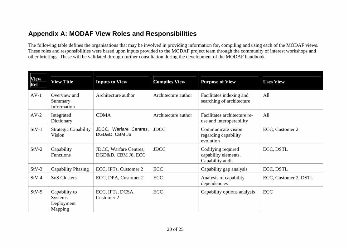
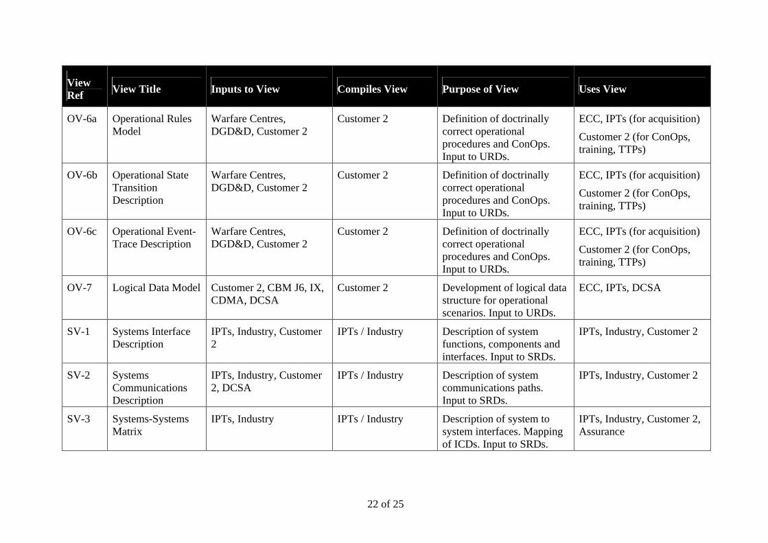
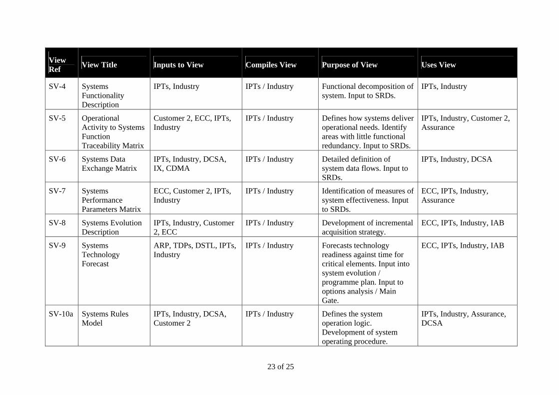
Appendix A: MODAF View Roles and Responsibilities
The following table defines the organisations that may be involved in providing information for, compiling and using each of the MODAF views. These roles and responsibilities were based upon inputs provided to the MODAF project team through the community of interest workshops and other briefings. These will be validated through further consultation during the development of the MODAF handbook.
View Ref
View Title Inputs to View Compiles View Purpose of View Uses View
AV-1 Overview and Summary Information
Architecture author Architecture author Facilitates indexing and searching of architecture
All
AV-2 Integrated Dictionary
CDMA Architecture author Facilitates architecture re-use and interoperability
All
StV-1 Strategic Capability Vision
JDCC, Warfare Centres, DGD&D, CBM J6
JDCC Communicate vision regarding capability evolution
ECC, Customer 2
StV-2 Capability Functions
JDCC, Warfare Centres, DGD&D, CBM J6, ECC
JDCC Codifying required capability elements. Capability audit
ECC, DSTL
StV-3 Capability Phasing ECC, IPTs, Customer 2 ECC Capability gap analysis ECC, DSTL
StV-4 SoS Clusters ECC, DPA, Customer 2 ECC Analysis of capability dependencies
ECC, Customer 2, DSTL
StV-5 Capability to Systems Deployment Mapping
ECC, IPTs, DCSA, Customer 2
ECC Capability options analysis ECC

21 of 25
View Ref
View Title Inputs to View Compiles View Purpose of View Uses View
OV-1 High-Level Operational Concept Graphic
Customer 2, ECC Customer 2 / ECC Depiction of operational scenarios. Definition of Use Cases within URDs.
ECC, IPTs (for acquisition)
Customer 2 (for training, TTPs)
OV-1b Concept of Operations
Customer 2 Customer 2 Description of Concept of Use associated with OV-1 operational scenario. Input to URDs.
ECC, IPTs (for acquisition)
Customer 2 (for training, TTPs)
OV-1c Operational Performance Parameters
Customer 2 Customer 2 Identification of measures of operational effectiveness for an operational scenario. Input to URDs.
ECC, IPTs, Assurance (for acquisition)
Customer 2 (for acceptance)
OV-2 Operational Node Connectivity Description
Customer 2, ECC Customer 2 / ECC Define roles and information flows for operational scenarios. Input to URDs.
ECC, IPTs (for acquisition)
Customer 2 (for IERs, training, TTPs)
OV-3 Operational Information Exchange Matrix
Customer 2, ECC, CBM J6, CDMA
Customer 2 / ECC Detailed definition of operational information flows. Input to URDs.
ECC, IPTs (for acquisition)
Customer 2 (for training, TTPs)
OV-4 Organizational Relationships Chart
Customer 2 Customer 2 Role relationships within operational scenarios.
Customer 2 (for IERs, training, TTPs)
OV-5 Operational Activity Model
Customer 2, ECC Customer 2 / ECC Detailed definition of operational processes. Input to URDs.
ECC, IPTs (for acquisition)
Customer 2 (for training, TTPs)
22 of 25
View Ref
View Title Inputs to View Compiles View Purpose of View Uses View
OV-6a Operational Rules Model
Warfare Centres, DGD&D, Customer 2
Customer 2 Definition of doctrinally correct operational procedures and ConOps. Input to URDs.
ECC, IPTs (for acquisition)
Customer 2 (for ConOps, training, TTPs)
OV-6b Operational State Transition Description
Warfare Centres, DGD&D, Customer 2
Customer 2 Definition of doctrinally correct operational procedures and ConOps. Input to URDs.
ECC, IPTs (for acquisition)
Customer 2 (for ConOps, training, TTPs)
OV-6c Operational Event-Trace Description
Warfare Centres, DGD&D, Customer 2
Customer 2 Definition of doctrinally correct operational procedures and ConOps. Input to URDs.
ECC, IPTs (for acquisition)
Customer 2 (for ConOps, training, TTPs)
OV-7 Logical Data Model Customer 2, CBM J6, IX, CDMA, DCSA
Customer 2 Development of logical data structure for operational scenarios. Input to URDs.
ECC, IPTs, DCSA
SV-1 Systems Interface Description
IPTs, Industry, Customer 2
IPTs / Industry Description of system functions, components and interfaces. Input to SRDs.
IPTs, Industry, Customer 2
SV-2 Systems Communications Description
IPTs, Industry, Customer 2, DCSA
IPTs / Industry Description of system communications paths. Input to SRDs.
IPTs, Industry, Customer 2
SV-3 Systems-Systems Matrix
IPTs, Industry IPTs / Industry Description of system to system interfaces. Mapping of ICDs. Input to SRDs.
IPTs, Industry, Customer 2, Assurance
23 of 25
View Ref
View Title Inputs to View Compiles View Purpose of View Uses View
SV-4 Systems Functionality Description
IPTs, Industry IPTs / Industry Functional decomposition of system. Input to SRDs.
IPTs, Industry
SV-5 Operational Activity to Systems Function Traceability Matrix
Customer 2, ECC, IPTs, Industry
IPTs / Industry Defines how systems deliver operational needs. Identify areas with little functional redundancy. Input to SRDs.
IPTs, Industry, Customer 2, Assurance
SV-6 Systems Data Exchange Matrix
IPTs, Industry, DCSA, IX, CDMA
IPTs / Industry Detailed definition of system data flows. Input to SRDs.
IPTs, Industry, DCSA
SV-7 Systems Performance Parameters Matrix
ECC, Customer 2, IPTs, Industry
IPTs / Industry Identification of measures of system effectiveness. Input to SRDs.
ECC, IPTs, Industry, Assurance
SV-8 Systems Evolution Description
IPTs, Industry, Customer 2, ECC
IPTs / Industry Development of incremental acquisition strategy.
ECC, IPTs, Industry, IAB
SV-9 Systems Technology Forecast
ARP, TDPs, DSTL, IPTs, Industry
IPTs / Industry Forecasts technology readiness against time for critical elements. Input into system evolution / programme plan. Input to options analysis / Main Gate.
ECC, IPTs, Industry, IAB
SV-10a Systems Rules Model
IPTs, Industry, DCSA, Customer 2
IPTs / Industry Defines the system operation logic. Development of system operating procedure.
IPTs, Industry, Assurance, DCSA
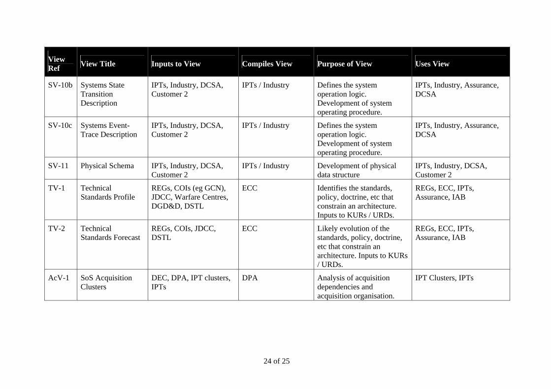
24 of 25
View Ref
View Title Inputs to View Compiles View Purpose of View Uses View
SV-10b Systems State Transition Description
IPTs, Industry, DCSA, Customer 2
IPTs / Industry Defines the system operation logic. Development of system operating procedure.
IPTs, Industry, Assurance, DCSA
SV-10c Systems Event-Trace Description
IPTs, Industry, DCSA, Customer 2
IPTs / Industry Defines the system operation logic. Development of system operating procedure.
IPTs, Industry, Assurance, DCSA
SV-11 Physical Schema IPTs, Industry, DCSA, Customer 2
IPTs / Industry Development of physical data structure
IPTs, Industry, DCSA, Customer 2
TV-1 Technical Standards Profile
REGs, COIs (eg GCN), JDCC, Warfare Centres, DGD&D, DSTL
ECC Identifies the standards, policy, doctrine, etc that constrain an architecture. Inputs to KURs / URDs.
REGs, ECC, IPTs, Assurance, IAB
TV-2 Technical Standards Forecast
REGs, COIs, JDCC, DSTL
ECC Likely evolution of the standards, policy, doctrine, etc that constrain an architecture. Inputs to KURs / URDs.
REGs, ECC, IPTs, Assurance, IAB
AcV-1 SoS Acquisition Clusters
DEC, DPA, IPT clusters, IPTs
DPA Analysis of acquisition dependencies and acquisition organisation.
IPT Clusters, IPTs
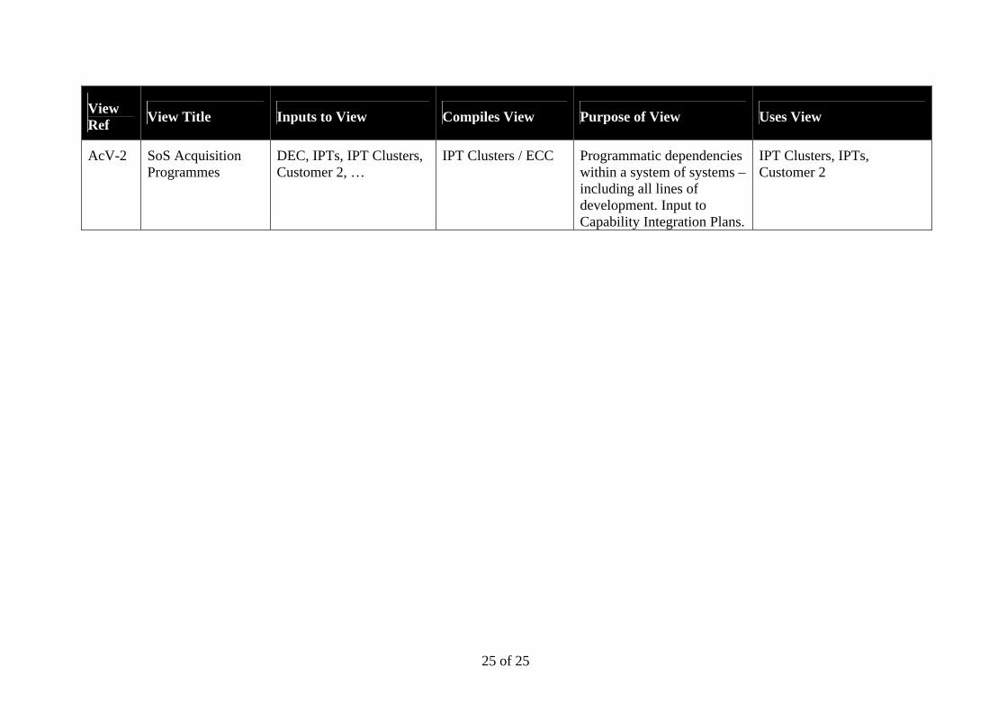
25 of 25
View Ref
View Title Inputs to View Compiles View Purpose of View Uses View
AcV-2 SoS Acquisition Programmes
DEC, IPTs, IPT Clusters, Customer 2, …
IPT Clusters / ECC Programmatic dependencies within a system of systems – including all lines of development. Input to Capability Integration Plans.
IPT Clusters, IPTs, Customer 2


