
— ABB meAsurement & AnAlytics | dAtA sheet
Model 266MRT, 266GRT, 266RRT and 266ART Differential, gauge and absolute pressure transmitters

2 266MRT, 266GRT, 266RRT and 266aRT differential gauge and absolute pressure transmit ters | ds/266Xrt-en rev. f
—Measurement made easyEngineered solutions for all applications
—Base accuracy•0.04 % of calibrated span
—Proven sensor technology together with state-of-the-art digital technology•large turn down ratio of up to 60:1
—Comprehensive selection of sensors•Optimized performance and stability
—Flexible configuration options•local configuration via keys on lcd indicator
—New TTG (Through-The-Glass) key technology•enables quick and easy local configuration without the need to open the
cover - even in environments with explosion protection
—IEC 61508 certification •For SIL2 (1oo1) and SIL3 (1oo2) applications
PED compliance to Sound Engineering Practice SEP

3266MRT, 266GRT, 266RRT and 266aRT differential gauge and absolute pressure transmit ters | ds/266Xrt-en rev. f
—
General descriptionthe diaphragm seal models described in this data sheet are combined with transmitters 266Xrt. One or two diaphragm seals can be connected to the transmitter via a capillary tube. the following models, which have different order codes, are available:
1 model 266mrt for differential pressure may be designed with either two diaphragm seals of the same type and size or with one diaphragm seal (on the high pressure (h) or low pressure (l) side) plus a standard process flange with threaded connection. in this case, the threaded connection (1/4 – 18 nPt or 1/2 – 14 nPt using adapter) is for the liquid or dry leg on the side opposite the diaphragm seal.
2 models 266Grt or 266Art / 266rrt for gauge pressure measurements with reference to atmospheric pressure or absolute pressure measurements with reference to vacuum are only equipped with one diaphragm seal. the table below lists the standard types of diaphragm seal that can be used together with transmitters 266Xrt.
For specifications and details of the diaphragm seals, please refer to the corresponding diaphragm seal data sheet ds/s26.differential pressure transmitters with two diaphragm seals:in all cases, the specifications below only apply to identical seal designs on both sides.
Diaphragm seal model diaphragm seal type seal diaphragm size (thickness) mnemonic symbol
S26WAS26WE
Waferdiaphragmseal(Asme and en standards)
1.5in./DN40 P1.5
2in./DN50 P2
3in./DN80 P3
1.5in./DN40(thin) F1.5
2in./DN50(thin) F2
3in./DN80(thin) F3
S26FAS26FES26RAS26RE
Flush diaphragm flanged seal(Asme and en standards;fixed and rotating flange)
2in./DN50 P2
3in./DN80 P3
4in./DN100 P3
2in./DN50(thin) F2
3in./DN80(thin) F3
4in./DN100(thin) F3
extended diaphragm flanged seal(Asme and en standards;
rotatingflangeS26RAandS26REonly)
2in./DN50 E2
3in./DN80 E3
4in./DN100 P3
S26RJ Flush diaphragm flanged seal(JISstandards;rotatingflangeonly)
A50 P2
A80 P3
A100 P3
S26RR Flush diaphragm flanged seal(ring joint in acc. with Asme standards; rotating flange)
1.5in. P1.5
2in. P2
3in. P3
S26CN Flanged diaphragm seal, "chemical tee" 3in. P3
S26TT Off-line diaphragm seal; threaded connection 21/2in. T2.5
S26MA,S26MEOff-line diaphragm seal; flange connection
(Asme and en standards) 21/2in. T2.5
S26SSdiaphragm seal with compression nut
triclampcherry Burrel
Aseptic diaphragm seal for sanitary applications
11/2in. K1.5
2in./F50 S2
3in./F80 S3
4in. S3
S26VN diaphragm seal for weld-on saddle flange or weld-in sleeve flange 21/2in. P1.5
S26UN threaded diaphragm seal for flange sleeve or welding spud 11/2in. Z1.5
S26BN Button diaphragm seal 1in. B1
S26PN Flanged diaphragm seal for urea service 11/2in. U1.5
21/2in. U2.5

4 266MRT, 266GRT, 266RRT and 266aRT differential gauge and absolute pressure transmit ters | ds/266Xrt-en rev. f
—
Functional specification
Measuring range limits and span limits
Sensor CodeMeasuring range upper limit (URL)
Measuring range lower limit (LRL) Minimum measuring span
266MRTDifferential pressure
266GRTGauge pressure
266RRTAbsolute pressure
266ARTAbsolute pressure
266MRT266GRT
266RRT266ART
c
6kPa -6kPa -6kPa 0.07kPaabs. 0.6kPa 1.2kPaabs(Δ)
60mbar -60mbar -60mbar 0.7mbarabs. 6mbar 12mbarabs(Δ)
24inH2O -24inH2O -24inH2O 0.5mmHg 2.41inH2O 9mmHg(Δ)
F40kPa -40kPa -40kPa 0.07kPaabs(§) 0.07kPaabs. 0.67kPa 2kPaabs.400mbar -400mbar -400mbar 0.7mbarabs(§) 0.7mbarabs. 6.7mbar 20mbarabs.160inH2O -160inH2O -160inH2O 0.5mmHg(§) 0.5mmHg 2.67inH2O 15mmHg
l250kPa -250kPa 0.07kPaabs(§) 0.07kPaabs(§) 0.07kPaabs(§) 4.17kPa 12.5kPaabs.2500mbar -2500mbar 0.7mbarabs(§) 0.7mbarabs(§) 0.7mbarabs(§) 41.67mbar 125mbarabs.1000inH2O -1000inH2O 0.5mmHg(§) 0.5mmHg(§) 0.5mmHg(§) 16.73inH2O 93.8mmHg
d
1000kPa 0.07kPaabs(§) 0.07kPaabs(§) 16.7kPa 50kPaabs(Δ)
10bar 0.7mbarabs(§) 0.7mbarabs(§) 167mbar 500mbarabs(Δ)
145psi 0.5mmHg(§) 0.5mmHg(§) 2.42psi 7.25psia(Δ)
n
2000kPa 0.07kPaabs(§) 33.3kPa 100kPaabs(#)
20bar -2000kPa-20bar-290psi
0.7mbarabs(§) 333mbar 1barabs(#)
290psi 0.5mmHg(§) 4.83psi 14.5psia(#)
u
3000kPa 0.07kPaabs(§) 0.07kPaabs(§) 50kPa 150kPaabs(Δ)
30bar 0.7mbarabs(§) 0.7mbarabs(§) 500mbar 1.5barabs(Δ)
450psi 0.5mmHg(§) 0.5mmHg(§) 7.25psi 21.7psia(Δ)
r
10000kPa 0.07kPaabs(§) 0.07kPaabs(§) 167kPa 500kPaabs(Δ)
100bar -10000kPa-100bar-1450psi
0.7mbarabs(§) 0.7mbarabs(§) 1.67bar 5barabs(Δ)
1450psi 0.5mmHg(§) 0.5mmHg(§) 24.17psi 72.6psia(Δ)
V
60000kPa 0.07kPaabs(§) 1000kPa
600bar 0.7mbarabs(§) 10bar
8700psi 0.5mmHg(§) 145psi
(§) Measuring range lower limit 0.135 kPa abs, 1.35 mbar abs, 1 mm Hg for fluorocarbon (Galden).(Δ) For 266ART only(#) For 266RRT only

5266MRT, 266GRT, 266RRT and 266aRT differential gauge and absolute pressure transmit ters | ds/266Xrt-en rev. f
Span limitsmaximum span = url(for differential pressure transmitter, can be adjusted up to ± url (td = 0.5) within the measuring range limits).
Importantto optimize measuring accuracy, it is recommended that you select the transmitter sensor code with the lowest turn down ratio.
Zero position suppression and elevationthe zero position and span can be set to any value within the measuring range limits listed in the table if:• set span ≥ minimum span
Dampingconfigurable time constant between 0 and 60 s.this is in addition to the sensor response time.
Warm-up timeready for operation as per specifications in less than 10 s with minimum damping.
Insulation resistance >100 mΩat500VDC(betweenterminalsandground).

6 266MRT, 266GRT, 266RRT and 266aRT differential gauge and absolute pressure transmit ters | ds/266Xrt-en rev. f
—Operating limitssee AlsO dAtA sheet ds/s26 FOr inFOrmAtiOn On Other POssiBle restrictiOns BAsed On diAPhrAGm seAl VERSIONS.
Pressure limitsOverpressure limits
Withoutdamagetothetransmitter
Models266MRTand266RRT
Filling fluid Overpressure limits
Sensors C to R Silicone oil
0.07kPaabs.,0.7mbarabs.,0.5mm hgand16MPa,160bar,2,320psi,or25MPa,250bar,3,625psi,or41MPa,410bar,5,945psidepending on code variant selected
Sensors C to RFluorocarbon
(Galden)
17.5kPaabs.,175mbarabs.,131mm hgand16MPa,160bar,2,320psi,or25MPa,250bar,3,625psi,or41MPa,410bar,5,945psidepending on code variant selected
Models266GRTand266ART
Filling fluid Overpressure limits
Sensor C, F -
0.07kPaabs.,0.7mbarabs.,0.5mm hgand1MPa,10bar,145psi
Sensor L Silicone oil
0.07kPaabs.,0.7mbarabs.,0.5mm hgand3MPa,30bar,435psi
Sensor D Silicone oil
0.07kPaabs.,0.7mbarabs.,0.5mm hgand6MPa,60bar,870psi
Sensor U Silicone oil
0.07kPaabs.,0.7mbarabs.,0.5mm hgand6MPa,60bar,870psi
Sensor R Silicone oil
0.07kPaabs.,0.7mbarabs.,0.5mm hgand30MPa,300bar,4350psi
Sensor V Silicone oil
0.07kPaabs.,0.7mbarabs.,0.5mm hgand90MPa,900bar,13050psi
Sensor LFluorocarbon
(Galden)
0.135kPaabs.,1.35mbarabs.,1mm hgand3MPa,30bar,435psi
Sensor DFluorocarbon
(Galden)
0.135kPaabs.,1.35mbarabs.,1mm hgand6MPa,60bar,870psi
Sensor UFluorocarbon
(Galden)
0.135kPaabs.,1.35mbarabs.,1mm hgand6MPa,60bar,870psi
Sensor RFluorocarbon
(Galden)
0.135kPaabs.,1.35mbarabs.,1mm hgand30MPa,300bar,4350psi
Sensor VFluorocarbon
(Galden)
0.135kPaabs.,1.35mbarabs.,1mm hgand90MPa,900bar,13050psi
Static pressure limitstransmitters for differential pressure, models 266mrt, can operate within the specifications with the following limit values.
Sensors Filling fluid Static pressure limits
Sensors C to R Silicone oil
3.5kPaabs.,35mbarabs.,0.5psiaand16MPa,160bar,2,320psi,or25MPa,250bar,3,625psi,or41MPa,410bar,5,945psidepending on code variant selected
Sensors C to RFluorocarbon
(Galden)
17.5kPaabs.,175mbarabs.,131mm hgand16MPa,160bar,2,320psi,or25MPa,250bar,3,625psi,or41MPa,410bar,5,945psidepending on code variant selected
The overpressure limits and upper static pressure limits can be lowered by means of the nominal pressure rating of the diaphragm seal flange; see diaphragm seal data sheet DS/S26.
Test pressurethe transmitters can withstand a pressure test with the following line pressure without leaking:
Model Test pressure
266MRT
1.5xnominalpressure(staticpressure limit) simultaneously on bothsides1
266RRT1xnominalpressure(staticpressurelimit)1
266GRT / 266ART Overpressure limits of sensor 1
1 Or double the value of the pressure sensor flange pressure stage, depending on which value is less.MeetshydrostatictestrequirementsofANSI/ISA–S82.03.

7266MRT, 266GRT, 266RRT and 266aRT differential gauge and absolute pressure transmit ters | ds/266Xrt-en rev. f
Temperature limits °C (°F)Environment
this is the operating temperature.
Models266MRT,266RRT Ambient temperature limitssilicone oil for sensors c to r -40 ... 85 °c (-40 ... 185 °F)
Fluorocarbon (Galden) for sensors c to r -40 ... 85 °c (-40 ... 185 °F)
Models266GRT,266ART Ambient temperature limitssilicone oil for sensor -40...85°C(-40...185°F)inert (Galden) for sensor -40...85°C(-40...185°F)Whiteoilforsensor -6...85°C(21...185°F)
Models266XRT Ambient temperature limitsintegrated lcd display -40...85°C(-40...185°F)
Below-20C(-4°F)andabove70°C(158°F),itmaynolongerbe possible to read the lcd display clearly.
ImportantFor applications in explosive environments, the temperature range specified on the certificate / approval applies dependent upon the degree of protection sought.
Process
Models266MRT(side without diaphragm seal)
Process temperature limits
silicone oil for sensors c to r -40...121°C(-40...250°F)1
Fluorocarbon (Galden) for sensors c to r -40...121°C(-40...250°F)2Vitongasket -20...121°C(-4...250°F)PtFe gasket -20...85°C(-4...185°F)
1 85 °C (185 °F) for applications under 10 kPa, 100 mbar abs., 1.45 psia up to 3.5 kPa abs., 35 mbar abs., 26 mm Hg2 85 °C (185 °F) for applications below atmospheric pressure up to 17.5 kPa abs., 175 mbar abs., 131 mm Hg
the table below contains the specifications for diaphragm seal filling fluids when used in transmitters with (a) diaphragm seal(s).
Filling fluid (application)
Process temperature and pressure limits
Tmax°C (°F)@ Pabs> than
Pminmbar abs(mm Hg)
Tmax°C (°F)@ Pmin
Tmin°C (°F)
SiliconeoilPMX20010cSt
250(480)@385mbar
0,7(0,5)
130(266)
-40(-40)
silicone oil Baysilone PD55cSt
250(480)@900mbar
0,7(0,5)
45(123)
-85(-121)
Fluorocarbon Galden G5(oxygen applications)
160(320)@1bar
2,1(1,52)
60(140)
-20(-4)
FluorocarbonHalocarbon4.2(oxygen applications)
180(356)@425mbar
4(3)
70(158)
-20(-4)
silicone polymer syltherm Xlt (cryogenic applications)
110(230)@118mbar
2,1(1,52)
20(68)
-100(-148)
SiliconeoilDC704(high-temperature applications)
375(707)@1bar
0,7(0,5)
220(328)
-10(14)
VegetableoilNeobeeM-20(foodandbeverage, sanitary applications) with FdA approval
200(390)@1bar
10(7,2)
20(68)
-18(0)
mineral oil esso Marcol122(foodandbeverage, sanitary applications) with FdA approval
250(480)@630mbar
0,7(0,5)
110(230)
-6(21)
Glycerinwater70%(food and beverage, sanitary applications) with FdA approval
93(200)@1bar
1000(760)
93(200)
-7(-20)

8 266MRT, 266GRT, 266RRT and 266aRT differential gauge and absolute pressure transmit ters | ds/266Xrt-en rev. f
—...Operating limits...Temperature limits °C (°F)
Flushing ring gasket material
Process limits
Pressure (max.) Temperature P x T
Garlock 6.9MPa,69bar,1,000psi
-73...204°C(-100...400°F)
250,000(°F x psi)
Graphite 2.5MPa,25bar,362psi
-100...380°C(-148...716°F)
PtFe 6MPa,60bar,870psi
-100...250°C(-148...482°F)
Storage
Models266XRT Storage temperature rangesilicone oil -50...85°C(-58...185°F)integral lcd display -40...85°C(-40...185°F)

9266MRT, 266GRT, 266RRT and 266aRT differential gauge and absolute pressure transmit ters | ds/266Xrt-en rev. f
—Limits for environmental effectsElectromagnetic compatibility (EMC)
meets requirements of en 61326 and namur ne-21Overvoltagestrength(withsurgeprotection):4kV(in acc. with iec 1000-4-5 en 61000-4-5).
Pressure Equipment Directive (PED)comply with 2014/68/ue to standard Ansi/isA 61010-1:2012 following sound engineering Practice (seP).
Humidityrelative humidity: up to 100 %.condensation, icing: Permissible.
Vibration resistanceAcceleration up to 2 g at frequencies of up to 1000 hz (according to iec 60068-2-6).Acceleration limited to 1 g for housing out of stainless steel.
Shock resistanceAcceleration: 50 gduration: 11 ms(according to iec 60068-2-27).
IP ratingInaccordancewithEN60529,JISC0920the transmitter is dust and sand proof and protected against immersion effects.• iP 67, iP 68 on request, nemA 4X• iP 65 (devices with harting han plug connector)• iP 66 (devices with barrel housing made from aluminum
or stainless steel housing)
Hazardous atmospheresWithorwithoutintegralLCDdisplay
Type of protection "Intrinsic safety":
ApprovalinaccordancewithATEXEuropa(codeE1)andIECEx(codeE8)II1GExiaIICT6/T5/T4andII1/2GExiaIICT6/T5/T4;IP67.II1DExiaD20T85°CandII1/2DExiaD21T85°C;IP67nePsi china (code ey)ExiaIICT4∼T6,DIPA20TA,T4~T6.
Type of protection "Flameproof (enclosure)”:
ApprovalinaccordancewithATEXEuropa(codeE2)andIECEx(codeE9)II1/2GExdIICT6andII1/2DExtDA21T85°C(–50°C≤ ta ≤+75°C);IP67.nePsi china (code eZ)ExdIICT6,DIPA21TA,T6.
Type of protection “nL”:
ATEXEuropa(codeE3)andIECEx(codeER)declaration of conformityII3GExnLIICT6/T5/T4andII3DExtDA22T85°C;IP67.nePsi china (code ey) declaration of conformityExnLIICT4∼T6,DIPA22TA,T6.
FMapprovalsforUSA(codeE6)andFMapprovalsforCanada(codeE4):
• Explosionproof(US):ClassI,Div.1,GroupsA,B,C,D• Explosionproof(Canada):ClassI,Div.1,GroupsB,C,D• Dustignitionproof:ClassII,Div.1,GroupsE,F,G• Suitablefor:ClassII,Div.2,GroupsF,G;ClassIII,Div.1,2• Nonincendive:ClassI,Div.2,GroupsA,B,C,D• Intrinsicallysafe:ClassI,II,III,Div.1,GroupsA,B,C,D,E,F,G
ClassI,Zone0AExiaIICT6/T4,Zone0(FMUS)
ClassI,Zone0ExiaIICT6/T4,Zone0(FMCanada)
ATEXcombined(codeEW=E1+E2+E3),(codeE7=E1+E2)
ATEXcombinedandFMapprovals(codeEN=EW+E4+E6)
Combined FM approvals for USA and Canada
• intrinsic safety (code eA)• Flameproof (enclosure) (code eB)• non–incendive (code ec)
IECcombined(codeEH=E8+E9),(codeEI=E8+E9+ER)
nePsi combined (code eP = ey + eZ), (code eQ = ey + eZ + es)
• eAc–ex (GOst) russia, Kazakhstan, Belarus, ), based on AteX• inmetro (Brazil), based on AteX
the permissible ambient temperature ranges (within the limits of 50 to 85 °c) are specified in the type examination certificates dependent upon the temperature class.

10 266MRT, 266GRT, 266RRT and 266aRT differential gauge and absolute pressure transmit ters | ds/266Xrt-en rev. f
—Specification – electrical data and options
HART® digital communication and 4 ... 20 mA outputPower supply
Thetransmitteroperatesfrom10.5...42VDCwithnoloadand is protected against reversed polarity (additional loadsenableoperationabove42VDC).during use in ex ia zones and in other intrinsically safe applications,thepowersupplymustnotexceed30VDC.
Minimum operating voltage
12.3VDC Devicewiththeoption“S2–overvoltageprotection”
10.8VDC Deviceswiththeoption“YE–NE21conformity”
RippleMax.20mVovera250Ω load as per hArt specifications.
Load limitationstotal loop resistance at 4 ... 20 mA and hArt:
r (kΩ)=Voltagesupply–Minimumoperatingvoltage(VDC) 22 mA
A minimum resistance of 250 Ω is required for hArt communication.
Surge protection (optional)Upto4kV• Voltage:1.2μs rise time / 50 μs delay time at half value• current: 8 μs rise time / 20 μs delay time at half value
Output signaltwo–wire output 4 – 20 mA, selectable by the operator: linear or square root output signal, characteristic curve with the exponents 3/2 or 5/2, square root for bidirectional flow, linearization table with 22 points (i.e. for level measurements in lateral, cylindric containers and spherical containers).the hArt communication provides the digital process variables which are superimposed on the 4 to 20 mA signal (protocol in accordance with Bell 202 FsK standard).
Output current limits (according to NAMUR standard)Overload condition• lower limit: 3.8 mA (configurable from 3.8 ... 4 mA)• upper limit: 20.5 mA (configurable from 20 ... 21 mA)
Alarm current• minimum alarm current: 3.6 mA (configurable from
3.6 ... 4 mA)• maximum alarm current: 21 mA (configurable from
20 ... 22 mA)default setting: high Alarm current
HART protocol
HARTrevision7(standard,asdefault)
HARTrevision5(optional,onrequest)
Output current limits (in accordance with NAMUR standard)Overload condition
• lower limit: 3.8 mA (configurable from 3.8 – 4 mA)• upper limit: 20.5 mA (configurable from 20 – 21 mA)
Alarm current
Adjustment range
minimum alarm current (low alarm current)
3.6mA(configurablefrom3.6–4mA)
maximum alarm current (high alarm current)
21mA(configurablefrom20–23mA)
maximum alarm current (high alarm current) for devices with “hArt sil –functionalsafety”
Limitedtomaximum22mA!(Fromelectronicversion7.1.15)
Standard setting: high alarm current
Process diagnostics (PILD)Plugged impulse line detection (Pild) generates a warning via hArt communication. the device can also be configured to drive the analog output signal to the "alarm current".

11266MRT, 266GRT, 266RRT and 266aRT differential gauge and absolute pressure transmit ters | ds/266Xrt-en rev. f
—
FOUNDATION FieldbusTM outputModel
link Active scheduler (lAs) capability implemented.manufacturer code: 000320 (hex)device type code: 0007 (hex)
Power supplyThetransmitteroperatesfrom9…32VDC,regardlessofpolarity, with or without surge protection.during use in eex ia zones, the power supply must not exceed24VDC(entitycertification)or17.5VDC(FISCOcertification) according to FF-816.
Current consumptionOperating (quiescent): 15 mAFault current limit value: 20 mA max.
Output signalPhysical layer in accordance with iec 11582 / en 611582; transmission using manchester ii modulation at 31.25 kbit/s.
Function blocks/execution period3 enhanced analog input blocks / 25 ms max. (each)1 extended Pid block / 40 ms max.1 standard arithmetic block / 25 ms1 standard input selector block / 25 ms1 standard control selector block / 25 ms1 standard signal characterization block / 25 ms1 standard integrator / totalizer block / 25 ms
Additional blocks1 enhanced resource block1 manufacturer-specific pressure with calibration transducer block1 manufacturer-specific advanced diagnostics transducer block1 manufacturer-specific local display transducer block
Number of link objects35
Number of VCRs 35
Output interfaceFOundAtiOn fieldbus digital communication protocol in accordance with standard h1; complies with specification V.1.7.FF registration in progress.
Transmitter interference modethe output signal is "frozen" at the last valid value in the event of significant transmitter interference, once this interference is detected by the self-diagnostics function (which also displays error states).in the event of electronics failures or short circuits, the transmitter consumption is electronically limited to a defined value (approx. 20 mA) in order to ensure network safety.
12 266MRT, 266GRT, 266RRT and 266aRT differential gauge and absolute pressure transmit ters | ds/266Xrt-en rev. f
—...Specification – electrical data and options
PROFIBUS PA outputModel
Pressure transmitter, compliant with Profile 3.0.1id number: 3450 (hex)
Power supplyThetransmitteroperatesfrom9…32VDC,regardlessofpolarity, with or without surge protection.Thepowersupplymustnotexceed17.5VDCwhenusedineex ia zones.intrinsically safe installation in accordance with FiscO model.
Current consumptionOperating (quiescent): 15 mAFault current limit value: 20 mA max.
Output signalPhysical layer in accordance with iec 1158-2 / en 61158-2; transmission using manchester ii modulation at 31.25 kbit/s
Output interfacePrOFiBus PA communication according to PrOFiBus dP 50170 Part 2 / din 19245 Parts 1-3.
Output cycle time25 ms
Data blocks1 "physical block"3 "analog input" blocks1 "pressure transducer block" with calibration1 "transducer block" for local display
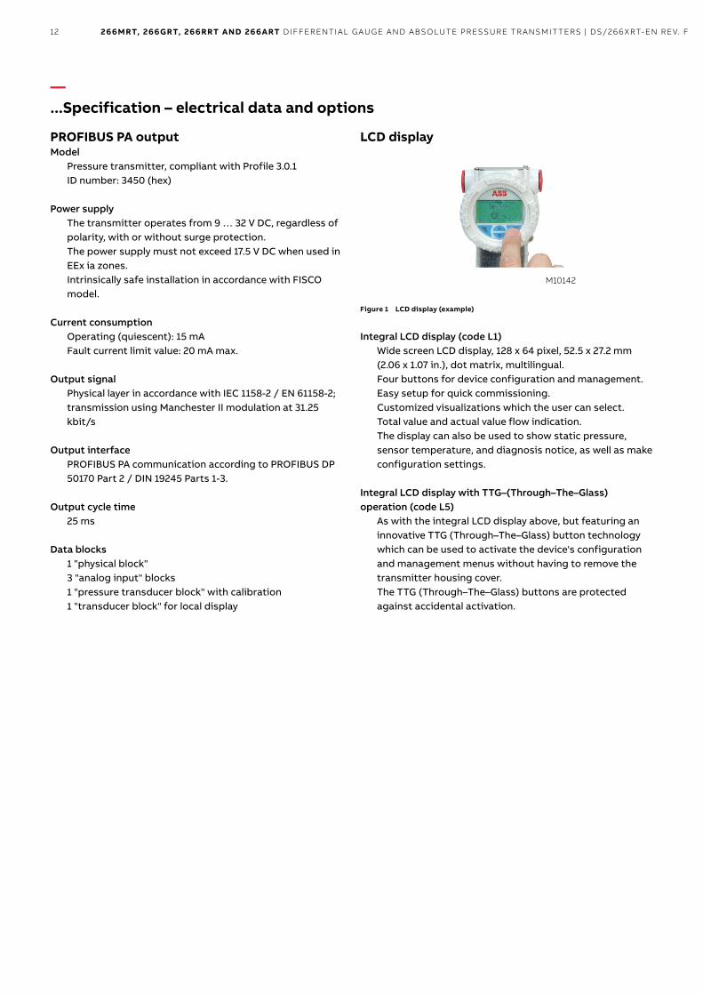
LCD display
Figure 1 LCD display (example)
Integral LCD display (code L1)WidescreenLCDdisplay,128x64pixel,52.5x27.2mm(2.06 x 1.07 in.), dot matrix, multilingual.Four buttons for device configuration and management.easy setup for quick commissioning.customized visualizations which the user can select.total value and actual value flow indication.the display can also be used to show static pressure, sensor temperature, and diagnosis notice, as well as make configuration settings.
Integral LCD display with TTG–(Through–The–Glass) operation (code L5)
As with the integral lcd display above, but featuring an innovative ttG (through–the–Glass) button technology which can be used to activate the device's configuration and management menus without having to remove the transmitter housing cover. the ttG (through–the–Glass) buttons are protected against accidental activation.
M10142

13266MRT, 266GRT, 266RRT and 266aRT differential gauge and absolute pressure transmit ters | ds/266Xrt-en rev. f
—Specification - measuring accuracy
measured with reference conditions acc. to iec 60770 environmentAmbient temperature 20 °c (68 °F), rel. humidity 65 %, atmospheric pressure 1,013 hPa (1,013 mbar), position of measuring cell (separation diaphragm areas) vertical, measuring span based on zero position, separation diaphragms made from stainless steel Aisi 316 l or hastelloy, silicone oil filling fluid, hArt digital trim values equal to 4 and 20 mA span end points, linear characteristic.unless otherwise stated, errors are specified as a % of the span value.some measuring accuracy levels relating to the upper measuring range limit (url) are affected by the current turn down (td); i.e., the ratio of the upper measuring range limit to the set span.FOr OPtimum meAsurinG AccurAcy, it is recOmmended thAt yOu select the trAnsmitter SENSORCODEWHICHWILLPROVIDETHELOWESTTDVALUE.
Measuring error% of calibrated span, consisting of terminal-based non-linearity, hysteresis, and non-repeatability.in the case of fieldbus devices, sPAn refers to the analog input function block output scale range.
Model Sensor For TD range Measuring error266MRTwith dF mnemonicP3,F3,E3,S3,F2
F to r From1:1to10:1 ±0.04%F to r From10:1to60:1 ±(0.04+0.005xTD-0.05)%c From1:1to5:1 ±0.04%
c From5:1to10:1 ±(0.008xTD)%266MRTwith dFmnemonicdifferentfrom above
F to r From1:1to10:1 ±0.065%F to r From10:1to60:1 ±(0.0065xTD)%c From1:1to5:1 ±0.065%
c From5:1to10:1 ±(0.013xTD)%
DF = Diaphragm seal
Model Sensor For TD range Measuring error266RRTwith dF mnemonicP3,F3,E3,S3,F2
F, l, n From1:1to10:1 ±0.04%
F, l, n From1:1to20:1 ±(0.04+0.005xTD-0.05)%
266RRTwith dFmnemonicdifferentfrom above
F, l, n From1:1to10:1 ±0.065%
F, l, n From1:1to20:1 ±(0.0065xTD)%
Model Sensor For TD range Measuring error266GRTwith dF mnemonicP3,F3,E3,S3,F2
FtoV From1:1to10:1 ±0.04%FtoV From10:1to60:1 ±(0.04+0.005xTD-0.05)%c From1:1to5:1 ±0.04%
c From5:1to10:1 ±(0.008xTD)%266GRTwith dFmnemonicdifferentfrom above
FtoV From1:1to10:1 ±0.065%FtoV From10:1to60:1 ±(0.0065xTD)%c From1:1to5:1 ±0.065%
c From5:1to10:1 ±(0.013xTD)%
Model Sensor For TD range Measuring error266ARTwith dF mnemonicP3,F3,E3,S3,F2
F to r From1:1to10:1 ±0.04%F to r From10:1to20:1 ±(0.04+0.005xTD-0.05)%
c From1:1to5:1 ±0.04%
266ARTwith dFmnemonicdifferentfrom above
F to r From1:1to10:1 ±0.065%F to r From10:1to20:1 ±(0.0065xTD)%
c From1:1to5:1 ±0.065%
Model Pabssensor(secondsensorfor266MRT)Measuringrange41MPa,410bar,5,945psi
266MRT c to r 80kPa,800mbar,321inH2O

14 266MRT, 266GRT, 266RRT and 266aRT differential gauge and absolute pressure transmit ters | ds/266Xrt-en rev. f
—...Specification – measuring accuracy
Ambient temperaturetransmitter effect per 20 K change within the limits of -40 to 85 °c(transmitter effect per 36 °F change within the limits of -40 to 185 °F):
Model Sensor For TD range266MRT c to r 10:1 ±(0.03%URL+0.045%span)266RRT F, l, n 10:1 ±(0.05%URL+0.08%span)266GRT c and F 10:1 ±(0.06%URL+0.09%span)266GRT LtoV 10:1 ±(0.03%URL+0.045%span)266ART c and F 5:1(C)10:1(F) ±(0.06%URL+0.09%span)266ART l to r 10:1 ±(0.03%URL+0.045%span)
Model 266MRT / Absolute pressure sensorFor the entire temperature range of 125 K, within the limits of –40 °c to 85 °c:• zero signal For sensors c to r: 40 kPa, 400 mbar, 160 in h2O (absolute pressure sensor 41mPa, 410 bar, 5,945 psi)• measuring span For sensors c to r: 0.3 mPa, 3 bar, 43.5 psi (absolute pressure sensor 41 mPa, 410 bar, 5,945 psi)
see dAtA sheet ds/s26 FOr AdditiOnAl temPerAture eFFects On the diAPhrAGm seAls:the total temperature effect can be defined as the combined influence of the factors referred to above on the transmitter plus the influence of the diaphragm seal, dependent upon the operating temperature.
Static pressuremodel 266mrt with diaphragm seal(s)(zero signal errors may be calibrated out at operating pressure)
Measuring range Sensors C, F, L, N Sensor R
Zero signal error
Upto100bar:0.05%URL
Upto100bar:0.1%URL
>100bar:0.05%URL/100bar
>100bar:0.1%URL/100bar
span error
Upto100bar:0.05%span
Upto100bar:0.1%span
>100bar:0.05%span/100bar
>100bar:0.1%span/100bar
Power supplyWithinthelimitvaluesforthevoltage/load,thetotalinfluence is less than 0.005 % of the upper measuring range limit per volt.
LoadWithintheload/voltagelimits,thetotalinfluenceisnegligible.
Electromagnetic fieldmeets all requirements of en 61326 and nAmur ne-21.
Common-mode interferenceNoinfluencefrom100Vrms@50Hz,or50VDC

15266MRT, 266GRT, 266RRT and 266aRT differential gauge and absolute pressure transmit ters | ds/266Xrt-en rev. f
—
Specification – physical(Please refer to the order information to check the availability of different versions of the relevant model)
MaterialsModel 266MRT only – Side without diaphragm sealProcess separation diaphragms 1
stainless steel (Aisi 316l - 1.4435)hastelloy c276;monel 400; tantalumA diaphragm seal with the required diaphragm material can be selected in this case too (as with the high pressure side).
Process flanges, adapters, screw plugs, and vent / drain valves 1
stainless steel Aisi 316l; hastelloy c276; monel 400
Screws and nutsscrews made from stainless steel Aisi 316, class A4-70 as per uni 7323 (isO 3506) in compliance with nAce mr0175 class ii.
Gaskets 1 Viton(FPM);Buna(NBR);EPDM;PTFE;graphite
Models 266MRT, 266RRT, 266GRT, 266ARTSeal diaphragm material (high pressure side) 1
stainless steel Aisi 316 l; hastelloy c-276;hastelloy c-2000; inconel 625; tantalum;stainless steel Aisi 316 l or hastelloy c-276 with non-stick coating;stainless steel Aisi 316 l with anti-corrosion coating;stainless steel Aisi 316 l, gold-plated;super duplex stainless steel (uns s32750 in acc. with Astm sA479);diaflex (Aisi with anti-abrasion treatment)
1 transmitter parts that come into contact with fluid
2 u-bolt material: stainless steel Aisi 400;
screw material: high-strength alloy steel or stainless steel Aisi 316
Diaphragm seal extension material 1 stainless steel Aisi 316 l (also for diaflex-coated and gold-plated diaphragm);hastelloy c-276; stainless steel Aisi 316 l or hastelloy c-276 with the same coating as the diaphragm.
Diaphragm seal filling fluidsilicone oil dc200; silicone oil dc704; fluorocarbon (Galden);Fluorocarbon halocarbon 4.2; silicone polymer syltherm Xlt;low-viscosity silicone oil Baysilone Pd5; glycerin water;vegetable oil neobee m-20; mineral oil esso marcol 122
Sensor filling fluidsilicone oil, fluorocarbon (Galden)
Sensor housingstainless steel (Aisi 316l)
Electronics housing and coverAluminum alloy (copper content ≤ 0.3 %) with baked epoxy finish (color: rAl 9002); stainless steel Aisi 316l.
O-ring coverBuna n (Perbunan)
Mounting bracket 2Galvanized c steel with chromium passivation; stainless steel Aisi 316.
Operating element for local zero point, measuring span, and write protection settings
non–intrusive design (removable) made of glass fiber reinforced polypropylene oxide.
Plates• transmitter name plate: stainless steel Aisi 316
fastened to the electronics housing.• certification plate and optional measuring point tag
plate / settings plate: Adhesive, fastened to the electronics housing or stainless steel Aisi 316l fastened to the electronics housing with rivets or screws.
• Optional tag plate with customer data: stainless steel Aisi 316l.
the metal plates are laser engraved, the adhesive signs thermo–printed.For stainless steel housings Aisi 316l, the order option i2 or i3 must be selected for plates made from stainless steel Aisi 316.

16 266MRT, 266GRT, 266RRT and 266aRT differential gauge and absolute pressure transmit ters | ds/266Xrt-en rev. f
—
...Specification – physical
Calibrationstandard:• 0 to measuring range upper limit, for ambient
temperature and atmospheric pressureOptional:• to specified measuring span
Optional extrasMounting bracket
For vertical and horizontal 60 mm (2 in.) pipes or wall mounting
LCD displaycan be rotated in 90° increments into 4 positions
Additional tag platescode i2: For measuring point tag (up to 30 characters) and calibration specifications (up to 30 characters: lower and upper value plus unit), attached to transmitter housing.code i1: For customer data (4 lines with 30 characters each), attached to transmitter housing with wire.
Overvoltage protection• code s2
Cleaning stage for oxygen application (O2)code P1
Certificates (inspection, implementation, characteristics, material certificate)
code cx and hx
Name plate and operating instruction languagecode tx and mx
Communication plug connectorcode ux
Valve manifold installationcode A1: Factory installation and pressure test of the ABB
m26 valve manifold.
Process connectionsOn standard process flange: 1/4-18 nPt on the process axisViaadapter:1/2-14NPTontheprocessaxisFastening screw threads: 7/16–20 unF with 41.3 mm center distanceProcess connection via diaphragm seal: see data sheet ds/s26
Electrical connectionstwo 1/2-14 nPt or m20 x 1.5 threaded bores for cable glands, directly on housing.special communication connector (on request)• hArt: straight or angled harting han 8d connector and
one mating plug.• FOundAtiOn fieldbus, PrOFiBus PA: m12 x 1 or 7/8 in.
plug
TerminalshArt version: three connections for signal / external display, for wire cross sections of up to 2.5 mm2(14AWG),and connection points for testing and communication purposesFieldbus versions: two signal connections (bus connection) for wire cross sections of up to 2.5 mm2 (14 AWG)
Groundinginternal and external ground terminals are provided for 6 mm2(10AWG)wirecrosssections.
Mounting positionthe transmitters can be installed in any position.the electronic housing can be rotated into any position. A stop is provided to prevent overturning.
Weight (without options or diaphragm seal)models 266mrt, 266rrt: Approx. 3.7 kg (8.2 lb)models 266Grt, 266Art: Approx. 2 kg (4.4 lb)Add 1.5 kg (3.3 lb) for stainless steel housings.Add 650 g (1.5 lb) for packaging.take into account additional weight of up to 50 kg (110 lb) for diaphragm seals.
Packagingcarton

17266MRT, 266GRT, 266RRT and 266aRT differential gauge and absolute pressure transmit ters | ds/266Xrt-en rev. f
—
Configuration
Transmitter with HART communication and 4 … 20 mAStandard configuration
transmitters are calibrated at the factory to the customer's specified measuring range. the calibrated range and measuring point number are provided on the name plate. if this data has not been specified, the transmitter will be delivered with the plate left blank and the following configuration:Physical unit kPa4 mA Zero20 mA measuring range upper limit (url)Output lineardamping 1 stransmitter interference mode high alarmsoftware tag (max. 8 characters) BlankOptionalLCDdisplay PVinkPa;outputinmA and in percent as bargraphAny or all of the configurable parameters listed above - including the lower and upper range values (with the same unit of measurement) - can easily be changed using a portable hArt handheld communicator or a Pc running the configuration software with the dtm for 266 models. specifications concerning the flange type and materials, O-ring and vent / drain valve materials, and additional device options are stored in the transmitter database.
Customer-specific configuration (option N6)the following information can be specified in addition to the standard configuration parameters:description 16 alphanumeric characterssupplementary information 32 alphanumeric charactersdate day, month, year
For the hArt protocol, the following physical units are available for pressure measurements:Pa, kPa, mPainh2O @ 4 °c, mmh2O @ 4 °c, psiinh2O @ 20 °c, fth2O @ 20 °c, mmh2O @ 20 °cinhg, mmhg, torrg/cm2, kg/cm2, atmmbar, barthese and others are available for PrOFiBus and FOundAtiOn fieldbus.
Transmitter with PROFIBUS PA communicationStandard configuration
transmitters are calibrated at the factory to the customer's specified measuring range. the calibrated range and measuring point number are provided on the name plate. if this data has not been specified, the transmitter will be delivered with the plate left blank and the following configuration:measuring profile PressurePhysical unit kPaOutput scale 0 % measuring range lower limit (lrl)Output scale 100 % measuring range upper limit (url)Output linearupper alarm limit measuring range upper limit (url)upper warning limit measuring range upper limit (url)lower warning limit measuring range lower limit (lrl)lower alarm limit measuring range lower limit (lrl)hysteresis limit value 0.5 % of output scalingPVfiltertime 0sAddress (set using local control buttons) 126measuring point tag 30 alphanumeric charactersOptionalLCDdisplay PVinkPa;outputinpercentas bargraph display
Any or all of the configurable parameters listed above - including the measuring range values (with the same unit of measurement) - can easily be changed using a Pc running the configuration software with the dtm for 266 models. specifications concerning the flange type and materials, O-ring and vent / drain valve materials, and additional device options are stored in the transmitter database.
Customer-specific configuration (option N6)the following information can be specified in addition to the standard configuration parameters:description 32 alphanumeric characterssupplementary information 32 alphanumeric charactersdate day, month, year
18 266MRT, 266GRT, 266RRT and 266aRT differential gauge and absolute pressure transmit ters | ds/266Xrt-en rev. f
—
...Configuration
Transmitter with FOUNDATION fieldbus communicationStandard configuration
transmitters are calibrated at the factory to the customer's specified measuring range. the calibrated range and measuring point number are provided on the name plate. if this data has not been specified, the transmitter will be delivered with the plate left blank and the analog input function block FB1 will be configured as follows:measuring profile PressurePhysical unit kPaOutput scale 0 % measuring range lower limit (lrl)Output scale 100 % measuring range upper limit (url)Output linearupper alarm limit measuring range upper limit (url)upper warning limit measuring range upper limit (url)lower warning limit measuring range lower limit (lrl)lower alarm limit measuring range lower limit (lrl)hysteresis limit value 0.5 % of output scalingPVfiltertime 0smeasuring point tag 30 alphanumeric charactersOptionalLCDdisplay PVinkPa;outputinpercentas bargraph displaythe analog input function blocks FB2 and FB3 are each configured for the sensor temperature measured in °c and the static pressure measured in mPa. Any or all of the configurable parameters listed above - including the measuring range values - can easily be changed using a FOundAtiOn fieldbus-compatible configuration tool. specifications concerning the flange type and materials, O-ring and vent / drain valve materials, and additional device options are stored in the transmitter database.
Customer-specific configuration (option n6)the following information can be specified in addition to the standard configuration parameters:description 32 alphanumeric characterssupplementary information 32 alphanumeric charactersdate day, month, year

19266MRT, 266GRT, 266RRT and 266aRT differential gauge and absolute pressure transmit ters | ds/266Xrt-en rev. f
—Mounting dimensions (not design data) - dimensions in mm (inch)Models 266MRT, 266RRT with barrel housing
Fig. 2: dimensions - Barrel housing
Importantin the case of model 266mrt with only one diaphragm seal, the threaded connection (1/4 – 18 nPt direct or 1/2 – 14 nPt via adapter) of the standard process flange, the gasket groove, and the gasket comply with iec 61518. the screw-on thread for attaching the adapter or other devices (e.g., manifold) to the process flange is 7/16-20 unF.
M10029-01
9
91 (3.58)
179
(7.0
2)
54 (2.13)
29 (1.14)18 (0.71)18 (0.71) 56 (2.21) 53 (2.09)
210
(8.2
8)
54 (2.13)
71(2.80)
settings
name plate
certification plate
Optional plate
code i2
Process connection
Vent/drainvalve
space for removing
the cover
terminal side
lcd housing cover
electronics side side

20 266MRT, 266GRT, 266RRT and 266aRT differential gauge and absolute pressure transmit ters | ds/266Xrt-en rev. f
—...Mounting dimensions ...(not design data) - dimensions in mm (inch)Models 266MRT, 266RRT with barrel housing and mounting bracket, for vertical or horizontal mounting on 60 mm (2 in.) pipe
Fig. 3: dimensions - Barrel housing with mounting bracket for vertical or horizontal mounting on 60 mm (2 in.) pipe

21266MRT, 266GRT, 266RRT and 266aRT differential gauge and absolute pressure transmit ters | ds/266Xrt-en rev. f
Models 266MRT, 266RRT with DIN housing and mounting bracket, for vertical or horizontal mounting on 60 mm (2 in.) pipe
Fig. 4: dimensions - din housing with mounting bracket for vertical or horizontal mounting on 60 mm (2 in.) pipe

22 266MRT, 266GRT, 266RRT and 266aRT differential gauge and absolute pressure transmit ters | ds/266Xrt-en rev. f
—...Mounting dimensions ...(not design data) - dimensions in mm (inch)Models 266MRT with barrel housing and flush mounting bracket, for vertical or horizontal mounting on 60 mm (2 in.) pipe
Fig. 5: dimensions - Barrel housing with flush mounting bracket for vertical or horizontal mounting on 60 mm (2 in.) pipe

23266MRT, 266GRT, 266RRT and 266aRT differential gauge and absolute pressure transmit ters | ds/266Xrt-en rev. f
Models 266GRT, 266ART with barrel housing and mounting bracket, for vertical or horizontal mounting on 60 mm (2 in.) pipe
Fig. 6: dimensions - Barrel housing with mounting bracket for vertical or horizontal mounting on 60 mm (2 in.) pipe
Models 266GRT, 266ART with DIN housing and mounting bracket, for vertical or horizontal mounting on 60 mm (2 in.) pipe
Fig. 7: dimensions - din housing with mounting bracket for vertical or horizontal mounting on 60 mm (2 in.) pipe

24 266MRT, 266GRT, 266RRT and 266aRT differential gauge and absolute pressure transmit ters | ds/266Xrt-en rev. f
—Electrical connectionsHART version
Fig. 8: electrical connections - hArt version
the hArt handheld terminal can be connected to any wiring termination point in the loop, provided there is a minimum resistance of 250 Ω between the handheld terminal and transmitter power supply. if this is less than 250 Ω, additional resistance needs to be incorporated in order to enable communication.
Fieldbus versions
7/8 inch
1 3
2 4
1
2
3
4
M12 x 1
M10007
Fig. 9: Plug connector - fieldbus versions
Pin assignment (plug)
Pin number FOUNDATION fieldbus PROFIBUS PA
1 DATA - DATA +
2 DATA + GROUND
3 SHIELD DATA -
4 GROUND SHIELD
delivery scope: Plug connectors supplied loose without mating plug (female connector)
Fig. 10: standard terminal strip
+
-+
+
- -
-
21
+Power source
remote indicator
handheld communicator
internal ground
termination point
line loadexternal ground
termination point
M10024-01
External ground terminal
Fieldbus line (independent
of the polarity)
Internal ground terminal

25266MRT, 266GRT, 266RRT and 266aRT differential gauge and absolute pressure transmit ters | ds/266Xrt-en rev. f
HART version
17.5 (0.69)78.5 (3.09)
Barrel-housing
141 (5.55)
DIN housing
29 (1.14)(*)
M10008-01
213
(8.3
9)
87 (3
.43)
187
(7.3
6)
138
(5.4
3)
Fig. 11: harting han connection – differential pressure transmitter (application example)
Barrel housing DIN housing
Fig. 12: harting han plug connector - gauge / absolute pressure transmitter (application example)
harting han 8d (8u)
socket insert for mating plug supplied
(view of sockets)

26 266MRT, 266GRT, 266RRT and 266aRT differential gauge and absolute pressure transmit ters | ds/266Xrt-en rev. f
—Ordering informationBasic ordering information model 266MRT Differential Pressure Transmitter with remote seal(s),maximum working pressure depending on seal / sensor limits
select one character or set of characters from each category and specify complete catalog number.refer to additional ordering information and specify one or more codes for each transmitter if additional options are required.
Basemodel-1stto6thcharacters 266MRT X X X X X X X
Differentialpressuretransmitterwithremoteseal(s),baseaccuracy0.04%
SensorSpanLimits–7thcharacter continued
on next page0.6and6kPa 6and60mbar 2.41and24in.H2O c
0.67and40kPa 6.7and400mbar 2.67and160in.H2O F
4.17and250kPa 41.7and2500mbar 16.7and1000in.H2O l
33.3and2000kPa 0.333and20bar 4.83and290psi n
167and10000kPa 1.67and100bar 24.2and1450psi r
MaximumWorkingPressure–8thcharacter
16MPa 160bar 2320psi c25MPa 250bar 3625psi Z41MPa 410bar 5945psi t
DiaphragmMaterial/FillFluid–9thcharacter
AISI316LSST(1.4435) silicone oil nAce s
Hastelloy®C-276 silicone oil nAce K
Monel400® silicone oil nAce m
AISI316Lssgoldplated silicone oil nAce V
tantalum silicone oil nAce t
AISI316LSST(1.4435) inert fluid – Galden (suitable for oxygen applications) nAce A
Hastelloy®C-276 inert fluid – Galden (suitable for oxygen applications) nAce F
Monel400®gold-plated inert fluid – Galden (suitable for oxygen applications) nAce c
AISI316Lssgoldplated inert fluid – Galden (suitable for oxygen applications) nAce y
tantalum inert fluid – Galden (suitable for oxygen applications) nAce d
diaphragm seal silicone oil (seal to be quoted separately) r
diaphragm seal inert fluid – Galden (seal to be quoted separately) 2
DiaphragmMaterial/FillFluid–9thcharacter
AISI316LSST(1.4404/1.4408) 1/4-18NPTfemaledirect (horizontal connection) nAce A
AISI316LSST(1.4404/1.4408) 1/2-14NPTfemalethroughadapter (horizontal connection) nAce B
AISI316LSST(1.4404/1.4408) 1/4-18NPTfemaledirect(DIN19213) (horizontal connection) nAce c
Hastelloy®C-276 1/4-18NPTfemaledirect (horizontal connection) nAce d
Hastelloy®C-276 1/2-14NPTfemalethroughadapter (horizontal connection) nAce e
Monel400® 1/4-18NPTfemaledirect (horizontal connection) nAce G
Monel400® 1/2-14NPTfemalethroughadapter (horizontal connection) nAce h
AISI316LSST(1.4404/1.4408) For two seals construction nAce r

27266MRT, 266GRT, 266RRT and 266aRT differential gauge and absolute pressure transmit ters | ds/266Xrt-en rev. f
X X X
BoltsMaterial/GasketsMaterial–11thcharacter
AISI316LSST(NACE-nonexposedtoH2S)/Viton(Suitableforoxygenapplications) 3
AISI316LSST(NACE-nonexposedtoH2S)/PTFE(Max.25MPa/250bar/3625psi) 4
AISI316LSST(NACE-nonexposedtoH2S)/EPDM 5
AISI316LSST(NACE-nonexposedtoH2S)/Perbunan 6
AISI316LSST(NACE-nonexposedtoH2S)/Graphite 7
AISI316LSST(NACE-nonexposedtoH2S)/Withoutgaskets(Fortwosealsconstruction) r
HousingMaterial/ElectricalConnection–12thcharacterAluminium alloy (Barrel type) 1/2-14NPT A
Aluminium alloy (Barrel type) M20x1.5 B
Aluminium alloy (Barrel type) harting han connector (General purpose only) (Note:1) e
Aluminium alloy (Barrel type) (General purpose only) (Note:1) G
AISI316LSST(Barreltype) s
AISI316LSST(Barreltype) t
Aluminium alloy (din type) J
Aluminium alloy (din type) (General purpose only) (Note:1) K
Aluminium alloy (din type) (General purpose only) (Note:1) W
AISI316LSST(Barreltype) (General purpose only) (Note:1) Z
Output–13thcharacter
HARTdigitalcommunicationand4…20mA 1
PrOFiBus PA 2
FOundAtiOn fieldbus 3
HARTdigitalcommunicationand4…20mA,SIL2andSIL3-certifiedinacc.withIEC61508 8

28 266MRT, 266GRT, 266RRT and 266aRT differential gauge and absolute pressure transmit ters | ds/266Xrt-en rev. f
—…Ordering informationADDITIONAL ORDERING INFORMATION for model 266MRT
Add one or more 2-digit code(s) after the basic ordering information to select all required options
XX XX
Vent and drain valve Material / Position
AISI316LSST(1.4404) On process axis nAce V1
AISI316LSST(1.4404) On flanges side top nAce V2
AISI316LSST(1.4404) On flanges side bottom nAce V3
Hastelloy®C-276 On process axis nAce V4
Hastelloy®C-276 On flanges side top nAce V5
Hastelloy®C-276 On flanges side bottom nAce V6
Monel400® On process axis nAce V7
Monel400® On flanges side top nAce V8
Monel400® On flanges side bottom nAce V9
Explosion Protection Certification
AteX intrinsic safety ex ia E1
AteX explosion Proof ex db E2
AteX intrinsic safety ex ic E3
FMapproval(Canada)(Onlyavailablewith1/2-14NPTorM20electricalconnections) E4
FMapproval(USA)(Onlyavailablewith1/2-14NPTorM20electricalconnections) E6
Fm approvals (usA and canada) intrinsic safety eA
Fm approvals (usA and canada) explosion Proof eB
Fm approvals (usA and canada) nonincendive ec
combined AteX, iecex and Fm approvals (usA and canada) en
combined AteX ex ia, ex db and ex ic EW
iecex intrinsic safety ex ia E8
iecex explosion Proof ex db E9
iecex intrinsic safety ex ic er
combined iec Approval ex ia and ex db eh
combined iec Approval ex ia, ex db and ex ic ei
nePsi intrinsic safety ex ia ey
nePsi explosion Proof ex d eZ
nePsi intrinsic safety ex ic es
combined nePsi ex ia and ex d eP
combined nePsi ex ia, ex d and ex ic eQ

29266MRT, 266GRT, 266RRT and 266aRT differential gauge and absolute pressure transmit ters | ds/266Xrt-en rev. f
XX XX XX XX XX XX
Other Explosion Protection Certifications
tr cu eAc ex ia russia (incl. GOst metrologic Approval) W1tr cu eAc ex d russia (incl. GOst metrologic Approval) W2tr cu eAc ex ia Kazakhstan (incl. GOst metrologic Approval) W3tr cu eAc ex d Kazakhstan (incl. GOst metrologic Approval) W4tr cu eAc ex ia Belarus (incl. GOst metrologic Approval) WF
tr cu eAc ex d Belarus (incl. GOst metrologic Approval) WG
Integral LCDWithintegralLCDdisplay L1
ttG (through the Glass) integral digital lcd display L5
Mounting Bracket Shape / MaterialFor pipe mounting / carbon steel (not suitable for Aisi housing) B1
Forpipemounting/AISI316SST(1.4401)(NotsuitableforAISIhousing) B2
Flattypebracket/AISI316SST(1.4401)(NotsuitableforAISIhousing) B5
Surge /Transient ProtectorWithintegralsurge/transientprotector S2
Operating Instruction LanguageGerman M1
italian M2
spanish M3
French M4
english M5
swedish M7
Polish M9
Portuguese mA
turkish mtLabel and Tag Language
German T1italian T2spanish T3Franch T4

30 266MRT, 266GRT, 266RRT and 266aRT differential gauge and absolute pressure transmit ters | ds/266Xrt-en rev. f
—…Ordering information...ADDITIONAL ORDERING INFORMATION for model 266MRT
Add one or more 2-digit code(s) after the basic ordering information to select all required options
XX XX XX XX
Additional Tag Plate
supplemental wired-on stainless steel plate I1
tag and certification stainless steel plates and laser printing of tag I2
tag, certification and supplemental wired-on stainless steel plates and laser printing of tag I3
Configuration
Standard–Pressure=inH2O/psiat68°F;Temperature=deg.F N2
Standard–Pressure=inH2O/psiat39.2°F;Temperature=deg.F N3
Standard–Pressure=inH2O/psiat20°C;Temperature=deg.C N4
Standard–Pressure=inH2O/psiat4°C;Temperature=deg.C N5
custom N6
ConfiguredforHARTrevision5 (Note:2) nh
Certificates
Inspectioncertificate3.1acc.EN10204ofcalibration C1
Inspectioncertificate3.1acc.EN10204ofheliumleakagetestofthesensormodule C4
Declarationofcompliancewiththeorder2.1acc.EN10204forinstrumentdesign C6
Printed record of configured data of transmitter cG
Pmi test on wetted parts ct
Approvals
GOst russia metrologic Approval Y1
GOst Kazakhstan metrologic Approval Y2
GOst ukraine metrologic Approval Y3
GOst Belarus metrologic Approval Y4
DetNorskeVeritasnavalapproval yA
ConformitytoNAMURNE021 ye

31266MRT, 266GRT, 266RRT and 266aRT differential gauge and absolute pressure transmit ters | ds/266Xrt-en rev. f
XX XX XX
Material Traceability
Inspectioncertificate3.1acc.EN10204ofpressure-bearingandprocesswettedpartswithanalysiscertificatesasmaterial
(Note:3) H3
Materialcertificate2.2acc.EN10204forthepressurebearingandprocesswettedparts H4
Connector
Fieldbus7/8in.(RecommendedforFOUNDATIONfieldbus,suppliedloosewithoutfemaleplug) U1
FieldbusM12x1(RecommendedforPROFIBUSPA,suppliedloosewithoutfemaleplug) U2
HartingHan8D(8U),straightentry U3
HartingHan8D(8U),angleentry U4
HartingHan7D U5
HartingHan8D(8U)-ForFour-Wireadd-onUnit U6
HartingHan7D-ForFour-Wireadd-onUnit U7
WithcableglandM20x1.5 U8
Seal Type High / Low Pressure Side
FororderinginformationpleaserefertosealdatasheetDS/S26
note 1: select connector with additional ordering code
note 2: not available with Output code 2, 3
note 3: minor parts with factory certificate acc. en 10204
Standard delivery scope (changes possible with additional ordering code)• Adapters supplied loose• Plugs for process axis (no vent / drain valves)• For standard applications (without explosion protection)• no display, no mounting bracket, no surge protection• multilanguage short-form operating instruction and english labeling• configuration with kPa and °c units• no test, inspection, or material certificates

32 266MRT, 266GRT, 266RRT and 266aRT differential gauge and absolute pressure transmit ters | ds/266Xrt-en rev. f
—…Ordering informationBasic ordering information for model 266RRT Absolute Pressure Transmitter with remote seal, overpressure depending on seal / sensor limits
select one character or set of characters from each category and specify complete catalog number.refer to additional ordering information and specify one or more codes for each transmitter if additional options are required.
Basemodel-1stto6thcharacters 266RRT X X X X X X
Absolutepressuretransmitterwithremoteseal,baseaccuracy0.04%
SensorSpanLimits–7thcharacter
2and40kPa 20and400mbar 8and160in.H2O 15and300mmHg F
12.5and250kPa 125and2500mbar 50and1000in.H2O 95and1875mmHg l
100and2000kPa 1and20bar 15and290psi n
MaximumWorkingPressure–8thcharacter
16MPa 160bar 2320psi c25MPa 250bar 3625psi Z41MPa 410bar 5945psi t
DiaphragmMaterial/FillFluid–9thcharacter
diaphragm seal silicone oil (seal to be quoted separately) r
diaphragm seal inert fluid – Galden (seal to be quoted separately) 2
ProcessConnectionMaterial/Type–10thcharacter
diaphragm seal (except button type, seal to be quoted separately) r
HousingMaterial/ElectricalConnection–11thcharacter
Aluminium alloy (Barrel type) 1/2-14NPT A
Aluminium alloy (Barrel type) M20x1.5 B
Aluminium alloy (Barrel type) harting han connector (General purpose only) (Note:1) e
Aluminium alloy (Barrel type) Fieldbus connector (General purpose only) (Note:1) G
AISI316LSST(Barreltype) 1/2-14NPT s
AISI316LSST(Barreltype) M20x1.5 t
Aluminium alloy (din type) M20x1.5 J
Aluminium alloy (din type) harting han connector (General purpose only) (Note:1) K
Aluminium alloy (din type) Fieldbus connector (General purpose only) (Note:1) W
AISI316LSST(Barreltype) Fieldbus connector (General purpose only) (Note:1) Z
Output–12thcharacter
HARTdigitalcommunicationand4…20mA(Optionsrequestedby“Additionalorderingcode”) 1
PROFIBUSPA(Optionsrequestedby“Additionalorderingcode”) 2
FOUNDATIONfieldbus(Optionsrequestedby“Additionalorderingcode”) 3
HARTdigitalcommunicationand4…20mA,SIL2andSIL3-certifiedtoIEC61508(Optionsrequestedby“Additionalorderingcode”) 8
33266MRT, 266GRT, 266RRT and 266aRT differential gauge and absolute pressure transmit ters | ds/266Xrt-en rev. f
—…Ordering informationAdditional ordering information for model 266RRT
Add one or more 2-digit code(s) after the basic ordering information to select all required options.
XX XX
Explosion Protection Certification
AteX intrinsic safety ex ia E1
AteX explosion Proof ex db E2
AteX intrinsic safety ex ic E3
FMapproval(Canada)(Onlyavailablewith1/2-14NPTorM20electricalconnections) E4
FMapproval(USA)(Onlyavailablewith1/2-14NPTorM20electricalconnections) E6
Fm approvals (usA and canada) intrinsic safety eA
Fm approvals (usA and canada) explosion Proof eB
Fm approvals (usA and canada) nonincendive ec
combined AteX, iecex and Fm approvals (usA and canada) en
combined AteX ex ia, ex db and ex ic EW
iecex intrinsic safety ex ia E8
iecex explosion Proof ex db E9
iecex intrinsic safety ex ic er
combined iec Approval ex ia and ex db eh
combined iec Approval ex ia, ex db and ex ic ei
nePsi intrinsic safety ex ia ey
nePsi explosion Proof ex d eZ
nePsi intrinsic safety ex ic es
combined nePsi ex ia and ex d eP
combined nePsi ex ia, ex d and ex ic eQ
Other Explosion Protection Certifications
tr cu eAc ex ia russia (incl. GOst metrologic Approval) W1
tr cu eAc ex d russia (incl. GOst metrologic Approval) W2
tr cu eAc ex ia Kazakhstan (incl. GOst metrologic Approval) W3
tr cu eAc ex d Kazakhstan (incl. GOst metrologic Approval) W4
tr cu eAc ex ia Belarus (incl. GOst metrologic Approval) WF
tr cu eAc ex d Belarus (incl. GOst metrologic Approval) WG

34 266MRT, 266GRT, 266RRT and 266aRT differential gauge and absolute pressure transmit ters | ds/266Xrt-en rev. f
—…Ordering information...Additional ordering information for model 266RRT
Add one or more 2-digit code(s) after the basic ordering information to select all required options.
XX XX XX XX XX XX
Integral LCD
WithintegralLCDdisplay L1
ttG (through the Glass) integral digital lcd display L5
Mounting Bracket Shape / MaterialFor pipe mounting / carbon steel (not suitable for Aisi housing) B1
Forpipemounting/AISI316SST(1.4401)(NotsuitableforAISIhousing) B2
Flattypebracket/AISI316SST(1.4401)(NotsuitableforAISIhousing) B5
surge /transient ProtectorWithintegralsurge/transientprotector S2
Operating Instruction LanguageGerman M1
italian M2
spanish M3
French M4
english M5
swedish M7
Polish M9
Portuguese mA
turkish mtLabel and Tag Language
German T1italian T2spanish T3French T4
Additional Tag PlateSupplementalwired-onstainlesssteelplate(4lines,32characterseach) I1laser printing of tag on stainless steel plate I2stainless steel tag, certification and wire-on plates I3

35266MRT, 266GRT, 266RRT and 266aRT differential gauge and absolute pressure transmit ters | ds/266Xrt-en rev. f
XX XX XX XX
Configuration
Standard–Pressure=inH2O/psiat68°F;Temperature=deg.F N2
Standard–Pressure=inH2O/psiat39.2°F;Temperature=deg.F N3
Standard–Pressure=inH2O/psiat20°C;Temperature=deg.C N4
Standard–Pressure=inH2O/psiat4°C;Temperature=deg.C N5
custom N6
ConfiguredforHARTrevision5 (Note:2) nh
Certificates
Inspectioncertificate3.1acc.EN10204ofcalibration C1
Inspectioncertificate3.1acc.EN10204ofheliumleakagetestofthesensormodule C4
Declarationofcompliancewiththeorder2.1acc.EN10204forinstrumentdesign C6
Printed record of configured data of transmitter cG
Pmi test on wetted parts ct
Approvals
GOst russia metrologic Approval Y1
GOst Kazakhstan metrologic Approval Y2
GOst ukraine metrologic Approval Y3
GOst Belarus metrologic Approval Y4
DetNorskeVeritasnavalapproval yA
ConformitytoNAMURNE021 ye
material traceability
Inspectioncertificate3.1acc.EN10204ofpressure-bearingandprocesswettedpartswithanalysiscertificatesasmaterial
verification (Note:3) H3
Materialcertificate2.2acc.EN10204forthepressurebearingandprocesswettedparts H4

36 266MRT, 266GRT, 266RRT and 266aRT differential gauge and absolute pressure transmit ters | ds/266Xrt-en rev. f
—…Ordering information...Additional ordering information for model 266RRT
Add one or more 2-digit code(s) after the basic ordering information to select all required options.
XX XX
Connector
Fieldbus7/8in.(RecommendedforFOUNDATIONfieldbus,suppliedloosewithoutfemaleplug) U1
FieldbusM12x1(RecommendedforPROFIBUSPA,suppliedloosewithoutfemaleplug) U2
HartingHan8D(8U),straightentry U3
HartingHan8D(8U),angleentry U4
HartingHan7D U5
HartingHan8D(8U)-ForFour-Wireadd-onUnit U6
HartingHan7D-ForFour-Wireadd-onUnit U7
WithcableglandM20x1.5 U8
seal type high Pressure side
FororderinginformationpleaserefertosealdatasheetDS/S26
note 1: select connector with additional ordering code
note 2: not available with Output code 2, 3
note 3: minor parts with factory certificate acc. en 10204
Standard delivery scope (changes possible with additional ordering code)• For standard applications (without explosion protection)• no display, no mounting bracket, no surge protection• multilanguage short-form operating instruction and english labeling• configuration with kPa and °c units• no test, inspection, or material certificates

37266MRT, 266GRT, 266RRT and 266aRT differential gauge and absolute pressure transmit ters | ds/266Xrt-en rev. f
—…Ordering informationMain ordering information for model 266GRT gauge pressure transmitter with remote diaphragm seal,overpressure limit dependent upon diaphragm seal / pressure sensor limits
select one or more characters from each category and enter the complete catalog number.enter one or more codes for additional order information if you are purchasing optional extras for each transmitter.
Basemodel-1stto6thcharacters 266GRT X X X X X
Gaugepressuretransmitterwithremoteseal,baseaccuracy0.04%
SensorSpanLimits–7thcharacter
0.6and6kPa 6and60mbar 2.41and24in.H2O /1MPa(10bar,145psi) c
0.67and40kPa 6.7and400mbar 2.67and160in.H2O /1MPa(10bar,145psi) F
4.17and250kPa 41.7and2500mbar 16.7and1000in.H2O /3MPa(30bar,435psi) l
16.7and1000kPa 0.167and10bar 2.42and145psi /6MPa(60bar,870psi) d
50and3000kPa 0.5and30bar 7.25and435psi /6MPa(60bar,870psi) u
167and10000kPa 1.67and100bar 24.2and1450psi /30MPa(300bar,4350psi) r
1000and60000kPa 10and600bar 145and8700psi /90MPa(900bar,13050psi) V
DiaphragmMaterial/FillFluid–8thcharacter
diaphragm seal mounted silicone oil (specify diaphragm seal separately) r
diaphragm seal mounted Fluorocarbon - Galden (specify diaphragm seal separately) 2
diaphragm seal mounted Whiteoil(specifydiaphragmsealseparately) n
ProcessConnectionMaterial/Type–9thcharacter
diaphragm seal (except in the case of button diaphragm seals, specify diaphragm seal separately) r
Button diaphragm seal (specify button diaphragm seal separately) G
direct mount diaphragm seal (one direct mount seal to be quoted) m
HousingMaterial/ElectricalConnection–10thcharacter
Aluminium alloy (Barrel type) 1/2-14NPT A
Aluminium alloy (Barrel type) M20x1.5 B
Aluminium alloy (Barrel type) harting han plug connector (for standard applications) (Note:1) e
Aluminium alloy (Barrel type) Fieldbus plug connector (for standard applications) (Note:1) G
stainless steel (Barrel type) 1/2-14NPT s
stainless steel (Barrel type) M20x1.5 t
Aluminium alloy (din type) M20x1.5 J
Aluminium alloy (din type) harting han plug connector (for standard applications) (Note:1) K
Aluminium alloy (din type) Fieldbus plug connector (for standard applications) (Note:1) W
stainless steel (Barrel type) Fieldbus plug connector (for standard applications) (Note:1) Z
Output–11thcharacter
HARTdigitalcommunicationand4…20mA(Optionsrequestedby“Additionalorderingcode”) 1
PROFIBUSPA(Optionsrequestedby“Additionalorderingcode”) 2
FOUNDATIONfieldbus(Optionsrequestedby“Additionalorderingcode”) 3
HARTdigitalcommunicationand4…20mA,SIL2andSIL3-certifiedtoIEC61508(Optionsrequestedby“Additionalorderingcode”) 8
38 266MRT, 266GRT, 266RRT and 266aRT differential gauge and absolute pressure transmit ters | ds/266Xrt-en rev. f
—…Ordering informationAdditional ordering information for model 266GRT
Add one or more 2-digit code(s) after the basic ordering information to select all required options.
XX XX
Explosion Protection Certification
AteX intrinsic safety ex ia E1
AteX explosion Proof ex db E2
AteX intrinsic safety ex ic E3
FMapproval(Canada)(Onlyavailablewith1/2-14NPTorM20electricalconnections) E4
FMapproval(USA)(Onlyavailablewith1/2-14NPTorM20electricalconnections) E6
Fm approvals (usA and canada) intrinsic safety eA
Fm approvals (usA and canada) explosion Proof eB
Fm approvals (usA and canada) nonincendive ec
combined AteX, iecex and Fm approvals (usA and canada) en
combined AteX ex ia, ex db and ex ic EW
iecex intrinsic safety ex ia E8
iecex explosion Proof ex db E9
iecex intrinsic safety ex ic er
combined iec Approval ex ia and ex db eh
combined iec Approval ex ia, ex db and ex ic ei
nePsi intrinsic safety ex ia ey
nePsi explosion Proof ex d eZ
nePsi intrinsic safety ex ic es
combined nePsi ex ia and ex d eP
combined nePsi ex ia, ex d and ex ic eQ
Other Explosion Protection Certifications
tr cu eAc ex ia russia (incl. GOst metrologic Approval) W1
tr cu eAc ex d russia (incl. GOst metrologic Approval) W2
tr cu eAc ex ia Kazakhstan (incl. GOst metrologic Approval) W3
tr cu eAc ex d Kazakhstan (incl. GOst metrologic Approval) W4
tr cu eAc ex ia Belarus (incl. GOst metrologic Approval) WF
tr cu eAc ex d Belarus (incl. GOst metrologic Approval) WG

39266MRT, 266GRT, 266RRT and 266aRT differential gauge and absolute pressure transmit ters | ds/266Xrt-en rev. f
XX XX XX XX XX XX
integral lcd
WithintegralLCDdisplay L1
ttG (through the Glass) integral digital lcd display L5
Mounting Bracket Shape / MaterialFor horizontal or vertical pipe and wall mounting / carbon steel B6
Forhorizontalorverticalpipeandwallmounting/AISI316(1.4401) B7
Overvoltage protectionWithovervoltageprotection(transientprotector) S2
Language of documentationGerman M1
italian M2
spanish M3
French M4
english M5
swedish M7
Polish M9
Portuguese mA
turkish mtLabel and Tag Language (material)
German T1italian T2spanish T3French T4
Additional Tag PlateTagplatemadefromstainlesssteel(4lineswith30characterseach) I1measuring point tag laser-printed onto stainless steel plate I2measuring point, certification and tag plate made from stainless steel I3

40 266MRT, 266GRT, 266RRT and 266aRT differential gauge and absolute pressure transmit ters | ds/266Xrt-en rev. f
—…Ordering information...Additional ordering information for model 266GRT
Add one or more 2-digit code(s) after the basic ordering information to select all required options.
XX XX XX XX
Configuration
Standard–Pressure=inH2O/psiat68°F;Temperature=deg.F N2
Standard–Pressure=inH2O/psiat39.2°F;Temperature=deg.F N3
Standard–Pressure=inH2O/psiat20°C;Temperature=deg.C N4
Standard–Pressure=inH2O/psiat4°C;Temperature=deg.C N5
custom N6
ConfiguredforHARTrevision5 (Note:2) nh
Certificates
Inspectioncertificate3.1acc.EN10204ofcalibration C1
Inspectioncertificate3.1acc.EN10204ofheliumleakagetestofthesensormodule C4
Declarationofcompliancewiththeorder2.1acc.EN10204forinstrumentdesign C6
Printed record of configured data of transmitter cG
Pmi test on wetted parts ct
Approvals
GOst russia metrologic Approval Y1
GOst Kazakhstan metrologic Approval Y2
GOst ukraine metrologic Approval Y3
GOst Belarus metrologic Approval Y4
DetNorskeVeritasnavalapproval yA
ConformitytoNAMURNE021 ye
material traceability
Inspectioncertificate3.1acc.EN10204ofpressure-bearingandprocesswettedpartswithanalysiscertificatesasmaterial
verification (Note:3) H3
Materialcertificate2.2acc.EN10204forthepressurebearingandprocesswettedparts H4

41266MRT, 266GRT, 266RRT and 266aRT differential gauge and absolute pressure transmit ters | ds/266Xrt-en rev. f
XX XX
Plug connector
Fieldbus7/8in.(RecommendedforFOUNDATIONfieldbus,suppliedloosewithoutfemaleplug) U1
FieldbusM12x1(RecommendedforPROFIBUSPA,suppliedloosewithoutfemaleplug) U2
HartingHan8D(8U),straightentry U3
HartingHan8D(8U),angleentry U4
HartingHan7D U5
HartingHan8D(8U)-ForFour-Wireadd-onUnit U6
HartingHan7D-ForFour-Wireadd-onUnit U7
WithcableglandM20x1.5 U8
Seal Type High / Low Pressure Side
FororderinginformationpleaserefertosealdatasheetDS/S26
note 1: select connector with additional ordering code
note 2: not available with Output code 2, 3
note 3: minor parts with factory certificate acc. en 10204
Standard delivery scope (changes possible with additional ordering code)• For standard applications (without explosion protection)• no display, no mounting bracket, no surge protection• multilanguage short-form operating instruction and english labeling• configuration with kPa and °c units• no test, inspection, or material certificates

42 266MRT, 266GRT, 266RRT and 266aRT differential gauge and absolute pressure transmit ters | ds/266Xrt-en rev. f
—…Ordering informationMain ordering information for model 266ART absolute pressure transmitter with remote diaphragm seal,overpressure limit dependent upon diaphragm seal / pressure sensor limits
select one or more characters from each category and enter the complete catalog number.enter one or more codes for additional order information if you are purchasing optional extras for each transmitter.
Basemodel-1stto6thcharacters 266ART X X X X X
Gaugepressuretransmitterwithremoteseal,baseaccuracy0.04%
SensorSpanLimits–7thcharacter
1.2and6kPa 12and60mbar 4.82and24in.H2O9and45mmHg /1MPa(10bar,145psi) c
2and40kPa 20and400mbar 15and300mmHg /1MPa(10bar,145psi) F
12.5and250kPa 125and2500mbar 93.8and1.875mmHg /3MPa(30bar,435psi) l
50and1000kPa 0.5and10bar 7.25and145psi /6MPa(60bar,870psi) d
150and3000kPa 1.5and30bar 21.7and435psi /6MPa(60bar,870psi) u
500and10000kPa 5and100bar 72.5and1450psi /30MPa(300bar,4350psi) r
DiaphragmMaterial/FillFluid–8thcharacter
diaphragm seal mounted silicone oil (specify diaphragm seal separately) r
diaphragm seal mounted Fluorocarbon - Galden (specify diaphragm seal separately) 2
diaphragm seal mounted Whiteoil(specifydiaphragmsealseparately) n
ProcessConnectionMaterial/Type–9thcharacter
diaphragm seal (except in the case of button diaphragm seals, specify diaphragm seal separately) r
Button diaphragm seal (specify button diaphragm seal separately) G
direct mount diaphragm seal (one direct mount seal to be quoted) m
HousingMaterial/ElectricalConnection–10thcharacter
Aluminium alloy (Barrel type) 1/2-14NPT A
Aluminium alloy (Barrel type) M20x1.5 B
Aluminium alloy (Barrel type) harting han plug connector (for standard applications) (Note:1) e
Aluminium alloy (Barrel type) Fieldbus plug connector (for standard applications) (Note:1) G
stainless steel (Barrel type) 1/2-14NPT s
stainless steel (Barrel type) M20x1.5 t
Aluminium alloy (din type) M20x1.5 J
Aluminium alloy (din type) harting han plug connector (for standard applications) (Note:1) K
Aluminium alloy (din type) Fieldbus plug connector (for standard applications) (Note:1) W
stainless steel (Barrel type) Fieldbus plug connector (for standard applications) (Note:1) Z
Output–11thcharacter
HARTdigitalcommunicationand4…20mA(Optionsrequestedby“Additionalorderingcode”) 1
PROFIBUSPA(Optionsrequestedby“Additionalorderingcode”) 2
FOUNDATIONfieldbus(Optionsrequestedby“Additionalorderingcode”) 3
HARTdigitalcommunicationand4…20mA,SIL2andSIL3-certifiedtoIEC61508(Optionsrequestedby“Additionalorderingcode”) 8

43266MRT, 266GRT, 266RRT and 266aRT differential gauge and absolute pressure transmit ters | ds/266Xrt-en rev. f
—…Ordering informationAdditional ordering information for model 266ART
Add one or more 2-digit code(s) after the basic ordering information to select all required options.
XX XX
Explosion Protection Certification
AteX intrinsic safety ex ia E1
AteX explosion Proof ex db E2
AteX intrinsic safety ex ic E3
FMapproval(Canada)(Onlyavailablewith1/2-14NPTorM20electricalconnections) E4
FMapproval(USA)(Onlyavailablewith1/2-14NPTorM20electricalconnections) E6
Fm approvals (usA and canada) intrinsic safety eA
Fm approvals (usA and canada) explosion Proof eB
Fm approvals (usA and canada) nonincendive ec
combined AteX, iecex and Fm approvals (usA and canada) en
combined AteX ex ia, ex db and ex ic EW
iecex intrinsic safety ex ia E8
iecex explosion Proof ex db E9
iecex intrinsic safety ex ic er
combined iec Approval ex ia and ex db eh
combined iec Approval ex ia, ex db and ex ic ei
nePsi intrinsic safety ex ia ey
nePsi explosion Proof ex d eZ
nePsi intrinsic safety ex ic es
combined nePsi ex ia and ex d eP
combined nePsi ex ia, ex d and ex ic eQ
Other Explosion Protection Certifications
tr cu eAc ex ia russia (incl. GOst metrologic Approval) W1
tr cu eAc ex d russia (incl. GOst metrologic Approval) W2
tr cu eAc ex ia Kazakhstan (incl. GOst metrologic Approval) W3
tr cu eAc ex d Kazakhstan (incl. GOst metrologic Approval) W4
tr cu eAc ex ia Belarus (incl. GOst metrologic Approval) WF
tr cu eAc ex d Belarus (incl. GOst metrologic Approval) WG

44 266MRT, 266GRT, 266RRT and 266aRT differential gauge and absolute pressure transmit ters | ds/266Xrt-en rev. f
—…Ordering information...Additional ordering information for model 266ART
Add one or more 2-digit code(s) after the basic ordering information to select all required options.
XX XX XX XX XX XX
Integral LCD
WithintegralLCDdisplay L1
ttG (through the Glass) integral digital lcd display L5
Mounting Bracket Shape / MaterialFor pipe mounting / carbon steel (not suitable for Aisi housing) B1
Forpipemounting/AISI316SST(1.4401)(NotsuitableforAISIhousing) B2
Flattypebracket/AISI316SST(1.4401)(NotsuitableforAISIhousing) B5
surge /transient ProtectorWithintegralsurge/transientprotector S2
Operating Instruction LanguageGerman M1
italian M2
spanish M3
French M4
english M5
swedish M7
Polish M9
Portuguese mA
turkish mtLabel and Tag Language
German T1italian T2spanish T3French T4
Additional Tag PlateSupplementalwired-onstainlesssteelplate(4lines,32characterseach) I1laser printing of tag on stainless steel plate I2stainless steel tag, certification and wire-on plates I3

45266MRT, 266GRT, 266RRT and 266aRT differential gauge and absolute pressure transmit ters | ds/266Xrt-en rev. f
XX XX XX XX
Configuration
Standard–Pressure=inH2O/psiat68°F;Temperature=deg.F N2
Standard–Pressure=inH2O/psiat39.2°F;Temperature=deg.F N3
Standard–Pressure=inH2O/psiat20°C;Temperature=deg.C N4
Standard–Pressure=inH2O/psiat4°C;Temperature=deg.C N5
custom N6
ConfiguredforHARTrevision5 (Note:2) nh
Certificates
Inspectioncertificate3.1acc.EN10204ofcalibration C1
Inspectioncertificate3.1acc.EN10204ofheliumleakagetestofthesensormodule C4
Declarationofcompliancewiththeorder2.1acc.EN10204forinstrumentdesign C6
Printed record of configured data of transmitter cG
Pmi test on wetted parts ct
Approvals
GOst russia metrologic Approval Y1
GOst Kazakhstan metrologic Approval Y2
GOst ukraine metrologic Approval Y3
GOst Belarus metrologic Approval Y4
DetNorskeVeritasnavalapproval yA
ConformitytoNAMURNE021 ye
material traceability
Inspectioncertificate3.1acc.EN10204ofpressure-bearingandprocesswettedpartswithanalysiscertificatesasmaterial
verification (Note:3) H3
Materialcertificate2.2acc.EN10204forthepressurebearingandprocesswettedparts H4

46 266MRT, 266GRT, 266RRT and 266aRT differential gauge and absolute pressure transmit ters | ds/266Xrt-en rev. f
—…Ordering information...Additional ordering information for model 266ART
Add one or more 2-digit code(s) after the basic ordering information to select all required options.
XX XX
Connector
Fieldbus7/8in.(RecommendedforFOUNDATIONfieldbus,suppliedloosewithoutfemaleplug) U1
FieldbusM12x1(RecommendedforPROFIBUSPA,suppliedloosewithoutfemaleplug) U2
HartingHan8D(8U),straightentry U3
HartingHan8D(8U),angleentry U4
HartingHan7D U5
HartingHan8D(8U)-ForFour-Wireadd-onUnit U6
HartingHan7D-ForFour-Wireadd-onUnit U7
WithcableglandM20x1.5 U8
seal type high Pressure side
FororderinginformationpleaserefertosealdatasheetDS/S26
note 1: select connector with additional ordering code
note 2: not available with Output code 2, 3
note 3: minor parts with factory certificate acc. en 10204
Standard delivery scope (changes possible with additional ordering code)• For standard applications (without explosion protection)• no display, no mounting bracket, no surge protection• multilanguage short-form operating instruction and english labeling• configuration with kPa and °c units• no test, inspection, or material certificates

47266MRT, 266GRT, 266RRT and 266aRT differential gauge and absolute pressure transmit ters | ds/266Xrt-en rev. f
IMPORTANT REMARK FOR ALL MODELS the selection of suitable wetted parts and filling fluid for compatibility with the process media is a customers responsibility, if not otherwise notified before manufacturing.
NACE compliance information1 the materials of constructions comply with metallurgical recommendations of nAce mr0175/isO 15156 for sour oil field
production environments. As specific environmental limits may apply to certain materials, please consult latest standard for further details. materials Aisi 316 / Aisi 316l, hastelloy c-276, monel 400 also conform to nAce mr0103 for sour refining environments.
2 nAce mr0175 addresses bolting requirements in two classes:• Exposed bolts: bolts directly exposed to the sour environment or buried, encapsulated or anyway not exposed to
atmosphere• Non exposed bolts: the bolting must not be directly exposed to sour environments, and must be directly exposed to the
atmosphere at all times.
266MRT,266RRTboltingidentifiedby“NACE”areincompliancetotherequirementsofNACEMR0175whenconsidered“nonexposedbolting”.
Trademarks ™ hastelloy c-276 is a cabot corporation trademark ™ hastelloy c-2000 is a haynes international trademark ™ monel is an international nickel co. trademark ™VitonisaDuPontdeNemourstrademark ™ dc200 is a dow corning corporation trademark ™ dc704 is a dow corning corporation trademark ™ Galden is a montefluos trademark ™ halocarbon is a halocarbon Products co. trademark ™ neobee m 20 is a stepan company trademark ™ esso marcol 122 is an esso italiana trademark ™ syltherm is a dow chemical company trademark

DS
/2
66
XR
T-E
N R
Ev
. F
11.
2018
—ABB Ltd. Measurement & AnalyticsHoward Road St. Neots Cambridgeshire PE19 8EU UK Tel: +44 (0)1480 475321 Fax: +44 (0)1480 217948
ABB Inc. Measurement & Analytics125 E. County Line Road Warminster PA 18974 USA Tel: +1 215 674 6000 Fax: +1 215 674 7183
abb.com/measurement
ABB S.p.A. Measurement & AnalyticsVia Luigi Vaccani 4 22016 Tremezzina Loc. Ossuccio (CO) Italy Tel: +39 0344 58111
ABB Automation Products GmbH Measurement & AnalyticsSchillerstr. 72 32425 Minden Germany Tel: +49 551 905 534 Fax: +49 551 905 555
We reserve the right to make technical changes or modify the contents of this document without prior notice. With regard to purchase orders, the agreed particulars shall prevail. ABB does not accept any responsibility whatsoever for potential errors or possible lack of information in this document.
We reserve all rights in this document and in the subject matter and illustrations contained therein. Any reproduction, disclosure to third parties or utilization of its contents – in whole or in parts – is forbidden without prior written consent of ABB.
© Copyright 2018 ABBAll rights reserved 3KXP200013R1001


