MPLS Traffic Engineering
Feature OverviewMultiprotocol Label Switching (MPLS) traffic engineering software enables an MPLS backbone to replicate and expand upon the traffic engineering capabilities of Layer 2 ATM and Frame Relay networks.
Traffic engineering is essential for service provider and Internet service provider (ISP) backbones. Such backbones must support a high use of transmission capacity, and the networks must be very resilient, so that they can withstand link or node failures.
MPLS traffic engineering provides an integrated approach to traffic engineering. With MPLS, traffic engineering capabilities are integrated into Layer 3, which optimizes the routing of IP traffic, given the constraints imposed by backbone capacity and topology.
MPLS traffic engineering:
• Enhances standard IGPs, such as IS-IS or OSPF, to automatically map packets onto the appropriate traffic flows.
• Transports traffic flows across a network using MPLS forwarding.
• Determines the routes for traffic flows across a network based on the resources the traffic flow requires and the resources available in the network.
• Employs "constraint-based routing," in which the path for a traffic flow is the shortest path that meets the resource requirements (constraints) of the traffic flow. In MPLS traffic engineering, the traffic flow has bandwidth requirements, media requirements, a priority versus other flows, and so on.
• Recovers to link or node failures that change the topology of the backbone by adapting to a new set of constraints.
Why Use MPLS Traffic Engineering?WAN connections are an expensive item in an ISP budget. Traffic engineering enables ISPs to route network traffic to offer the best service to their users in terms of throughput and delay. By making the service provider more efficient, traffic engineering reduces the cost of the network.
Currently, some ISPs base their services on an overlay model. In the overlay model, transmission facilities are managed by Layer 2 switching. The routers see only a fully meshed virtual topology, making most destinations appear one hop away. If you use the explicit Layer 2 transit layer, you can precisely control the ways in which traffic uses available bandwidth. However, the overlay model
MPLS Traffic Engineering 1
How MPLS Traffic Engineering Works
has a number of disadvantages. MPLS traffic engineering provides a way to achieve the same traffic engineering benefits of the overlay model without needing to run a separate network, and without needing a non-scalable, full mesh of router interconnects.
Existing Cisco IOS software releases (for example, Cisco IOS Release 11.1) contains a set of features that enable elementary traffic engineering capabilities. Specifically, you can create static routes and control dynamic routes through the manipulation of link state metrics. This functionality is useful in some tactical situations, but is insufficient for all the traffic engineering needs of ISPs.
MPLS traffic engineering has the following features:
• Packet transport using MPLS forwarding crossing a multihop label-switched path (LSP).
• Routing and signalling capability of LSPs across a backbone topology that can:
— Understand the backbone topology and available resources
— Account for link bandwidth and for the size of the traffic flow when determining routes for LSPs across the backbone.
— Has a dynamic adaptation mechanism that enables the backbone to be resilient to failures, even if several primary paths are precalculated off-line.
• Enhancements to the IGP (IS-IS or OSPF) SPF calculations to automatically calculate what traffic should be sent over what LSPs.
How MPLS Traffic Engineering WorksMPLS is an integration of Layer 2 and Layer 3 technologies. By making traditional Layer 2 features available to Layer 3, MPLS enables traffic engineering. Thus, you can offer in a one-tier network what now can be achieved only by overlaying a Layer 3 network on a Layer 2 network.
MPLS traffic engineering automatically establishes and maintains LSPs across the backbone, using RSVP. The path used by a given LSP at any point in time is determined based on the LSP resource requirements and network resources, such as bandwidth.
Available resources are flooded via extensions to a link-state based Interior Gateway Protocol (IGP).
Paths for LSPs are calculated at the LSP head based on a fit between required and available resources (constraint-based routing). The IGP automatically routes the traffic onto these LSPs. Typically, a packet crossing the MPLS traffic engineering backbone travels on a single LSP that connects the ingress point to the egress point.
MPLS traffic engineering is built on the following IOS mechanisms:
• IOS tunnel interfaces
From a Layer 2 standpoint, an LSP tunnel interface represents the head of an LSP. It is configured with a set of resource requirements, such as bandwidth and media requirements, and priority.
From a Layer 3 standpoint, an LSP tunnel interface is the head-end of a unidirectional virtual link to the tunnel destination.
• An MPLS traffic engineering path calculation module
This mechanism operates at the LSP head. It determines a path to use for an LSP using a link-state database containing flooded topology and resource information.
• RSVP with traffic engineering extensions
It operates at each LSP hop and is used to signal and maintain LSPs based on the calculated path.
• An MPLS traffic engineering link management module
2 Cisco IOS Release 12.0(8)S
Mapping Traffic into Tunnels
This module operates at each LSP hop, does link call admission on the RSVP signalling messages and bookkeeping of topology and resource information to be flooded.
• A link-state IGP (IS-IS or OSPF—each with traffic engineering extensions)
These IGPs are used to globally flood topology and resource information from the link management module.
• Enhancements to the SPF calculation used by the link-state IGP (IS-IS or OSPF)
they automatically route traffic onto the appropriate LSP tunnel based on tunnel destination. Static routes may also be used to direct traffic onto LSP tunnels.
• Label switching forwarding
This forwarding mechanism provides routers with a Layer 2-like ability to direct traffic across multiple hops of the LSP as established by RSVP signalling.
One approach to engineer a backbone is to define a mesh of tunnels from every ingress device to every egress device. The MPLS traffic engineering path calculation and signalling modules determine the path taken by the LSPs for these tunnels, subject to resource availability and the dynamic state of the network. The IGP, operating at an ingress device, determines which traffic should go to which egress device, and steers that traffic into the tunnel from ingress to egress.
Sometimes, a flow from an ingress device to egress device is so large that it cannot fit over a single link, so it cannot be carried by a single tunnel. In this case multiple tunnels between a given ingress and egress can be configured, and the flow is load shared among them.
For more information about MPLS (also referred to as Tag Switching), see the following Cisco documentation:
• Cisco IOS Release 12.0 Switching Services Configuration Guide, “Tag Switching” chapter.
• Cisco IOS Release 12.0 Switching Services Command Reference, “Tag Switching Commands” chapter.
Mapping Traffic into TunnelsThis section describes how conventional hop-by-hop link-state routing protocols interact with MPLS traffic engineering capabilities. In particular, this section describes how the shortest path first (SPF) algorithm, sometimes called a Dijkstra algorithm, has been enhanced so that a link-state IGP can automatically forward traffic over tunnels that are set up by MPLS traffic engineering.
Link-state protocols, like integrated IS-IS or OSPF, use an SPF algorithm to compute a shortest path tree to all nodes in the network. Routing tables are derived from this shortest path tree. The routing tables contain ordered sets of destination and first-hop information. If a router does normal hop-by-hop routing, the first hop is a physical interface attached to the router.
New traffic engineering algorithms calculate explicit routes to one or more nodes in the network. These explicit routes are viewed as logical interfaces by the originating router. In the context of this document, these explicit routes are represented by LSPs and referred to as traffic engineering tunnels (TE tunnels).
The following sections describe how link-state IGPs can make use of these shortcuts, and how they can install routes in the routing table that point to these TE tunnels. These tunnels use explicit routes, and the path taken by a TE tunnel is controlled by the router that is the head-end of the tunnel. In the absence of errors, TE tunnels are guaranteed not to loop, but routers must agree on how to use the TE tunnels. Otherwise traffic might loop through two or more tunnels.
MPLS Traffic Engineering 3

How MPLS Traffic Engineering Works
Enhancement to the SPF ComputationDuring each step of the SPF computation, a router discovers the path to one node in the network. If that node is directly connected to the calculating router, the first-hop information is derived from the adjacency database. If a node is not directly connected to the calculating router, the node inherits the first-hop information from the parent(s) of that node. Each node has one or more parents and each node is the parent of zero or more downstream nodes.
For traffic engineering purposes, each router maintains a list of all TE tunnels that originate at this router. For each of those TE tunnels, the router at the tail-end is known.
During the SPF computation, the TENT (tentative) list stores paths that are only possibly the best paths and the PATH list stores paths that are definitely the best paths. When it is determined that a path is the best possible path, the node is moved from TENT to PATH. PATH is thus the set of nodes for which the best path from the computing router has been found. Each PATH entry consists of ID, path cost, and forwarding direction.
The router must determine the first-hop information. There are three possible ways to do this:
1 Examine the list of tail-end routers directly reachable by way of a TE tunnel. If there is a TE tunnel to this node, use the TE tunnel as the first hop.
2 If there is no TE tunnel, and the node is directly connected, use the first-hop information from the adjacency database.
3 If the node is not directly connected, and is not directly reachable by way of a TE tunnel, the first-hop information is copied from the parent node(s) to the new node.
As a result of this computation, traffic to nodes that are the tail end of TE tunnels flows over the TE tunnels. Traffic to nodes that are downstream of the tail-end nodes also flows over the TE tunnels. If there is more than one TE tunnel to different intermediate nodes on the path to destination node X, traffic flows over the TE tunnel whose tail-end node is closest to node X.
Special Cases and ExceptionsThe SPF algorithm finds equal-cost parallel paths to destinations. The enhancement previously described does not change this. Traffic can be forwarded over one or more native IP paths, over one or more TE tunnels, or over a combination of native IP paths and TE tunnels.
A special situation occurs in the following topology:
Assume that all links have the same cost and that a TE tunnel is set up from Router A to Router D. When the SPF calculation puts Router C on the TENT list, it realizes that Router C is not directly connected. It uses the first-hop information from the parent, which is Router B. When the SPF
Router A Router B Router C
Router D Router E
2668
2
4 Cisco IOS Release 12.0(8)S

Mapping Traffic into Tunnels
calculation on Router A puts Router D on the TENT list, it realizes that Router D is the tail end of a TE tunnel. Thus Router A installs a route to Router D by way of the TE tunnel, and not by way of Router B.
When Router A puts Router E on the TENT list, it realizes that Router E is not directly connected, and that Router E is not the tail end of a TE tunnel. Therefore Router A copies the first-hop information from the parents (Router C and Router D) to the first-hop information of Router E.
Traffic to Router E now load balances over the native IP path by way of Router A to Router B to Router C, and the TE tunnel Router A to Router D.
If parallel native IP paths and paths over TE tunnels are available, these implementations allow you to force traffic to flow over TE tunnels only or only over native IP paths.
Additional Enhancements to SPF Computation Using Configured Tunnel MetricsWhen an IGP route is installed into a router information base (RIB) by means of TE tunnels as next hops, the distance or metric of the route must be calculated. Normally, you could make the metric the same as the IGP metric over native IP paths as if the TE tunnels did not exist. For example, Router A can reach Router C with the shortest distance of 20. X is a route advertised in IGP by Router C. Route X is installed in Router A's RIB with the metric of 20. When a TE tunnel from Router A to Router C comes up, by default the route is installed with a metric of 20, but the next-hop information for X is changed.
Although the same metric scheme can work well in other situations, for some applications it is useful to change the TE tunnel metric. For instance, when there are equal cost paths through TE tunnel and native IP links. You can adjust TE tunnel metrics to force the traffic to prefer the TE tunnel, to prefer the native IP paths, or to load share among them.
Again, suppose that multiple TE tunnels go to the same or different destinations. TE tunnel metrics can force the traffic to prefer some TE tunnels over others, regardless of IGP distances to those destinations.
Setting metrics on TE tunnels does not affect the basic SPF algorithm. It affects only two questions in only two areas: (1) whether the TE tunnel is installed as one of the next hops to the destination routers, and (2) what the metric value is of the routes being installed into the RIB. You can modify the metrics for determining the first-hop information:
• If the metric of the TE tunnel to the tail-end routers is higher than the metric for the other TE tunnels or native hop-by-hop IGP paths, this tunnel is not installed as the next hop.
• If the metric of the TE tunnel is equal to the metric of either other TE tunnels or native hop-by-hop IGP paths, this tunnel is added to the existing next hops.
• If the metric of the TE tunnel is lower than the metric of other TE tunnels or native hop-by-hop IGP paths, this tunnel replaces them as the only next hop.
In each of the above cases, routes associated with those tail-end routers and their downstream routers are assigned metrics related to those tunnels.
This mechanism is loop free because the traffic through the TE tunnels is basically source routed. The end result of TE tunnel metric adjustment is the control of traffic loadsharing. If there is only one way to reach the destination through a single TE tunnel, then no matter what metric is assigned, the traffic has only one way to go.
You can represent the TE tunnel metric in two different ways: (1) as an absolute (or fixed) metric or (2) as a relative (or floating) metric.
MPLS Traffic Engineering 5
How MPLS Traffic Engineering Works
If you use an absolute metric, the routes assigned with the metric are fixed. This metric is used not only for the routes sourced on the TE tunnel tail-end router, but also for each route downstream of this tail-end router that uses this TE tunnel as one of its next hops.
For example, if you have TE tunnels to two core routers in a remote point of presence (POP), and one of them has an absolute metric of 1, all traffic going to that POP traverses this low-metric TE tunnel.
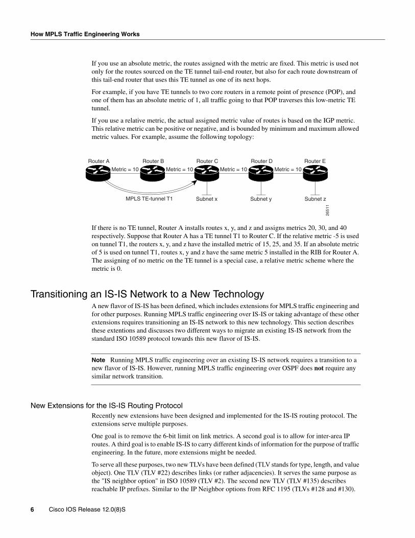
If you use a relative metric, the actual assigned metric value of routes is based on the IGP metric. This relative metric can be positive or negative, and is bounded by minimum and maximum allowed metric values. For example, assume the following topology:
If there is no TE tunnel, Router A installs routes x, y, and z and assigns metrics 20, 30, and 40 respectively. Suppose that Router A has a TE tunnel T1 to Router C. If the relative metric -5 is used on tunnel T1, the routers x, y, and z have the installed metric of 15, 25, and 35. If an absolute metric of 5 is used on tunnel T1, routes x, y and z have the same metric 5 installed in the RIB for Router A. The assigning of no metric on the TE tunnel is a special case, a relative metric scheme where the metric is 0.
Transitioning an IS-IS Network to a New TechnologyA new flavor of IS-IS has been defined, which includes extensions for MPLS traffic engineering and for other purposes. Running MPLS traffic engineering over IS-IS or taking advantage of these other extensions requires transitioning an IS-IS network to this new technology. This section describes these extentions and discusses two different ways to migrate an existing IS-IS network from the standard ISO 10589 protocol towards this new flavor of IS-IS.
Note Running MPLS traffic engineering over an existing IS-IS network requires a transition to a new flavor of IS-IS. However, running MPLS traffic engineering over OSPF does not require any similar network transition.
New Extensions for the IS-IS Routing ProtocolRecently new extensions have been designed and implemented for the IS-IS routing protocol. The extensions serve multiple purposes.
One goal is to remove the 6-bit limit on link metrics. A second goal is to allow for inter-area IP routes. A third goal is to enable IS-IS to carry different kinds of information for the purpose of traffic engineering. In the future, more extensions might be needed.
To serve all these purposes, two new TLVs have been defined (TLV stands for type, length, and value object). One TLV (TLV #22) describes links (or rather adjacencies). It serves the same purpose as the "IS neighbor option" in ISO 10589 (TLV #2). The second new TLV (TLV #135) describes reachable IP prefixes. Similar to the IP Neighbor options from RFC 1195 (TLVs #128 and #130).
Metric = 10 Metric = 10
Subnet xMPLS TE-tunnel T1
Metric = 10 Metric = 10
Router A Router B Router C Router D Router E
Subnet y Subnet z
2651
1
6 Cisco IOS Release 12.0(8)S
Transitioning an IS-IS Network to a New Technology
Both new TLVs have a fixed length part, followed by optional sub-TLVs. The metric space in these new TLVs has been enhanced from 6 bits to 24 or 32 bits. The sub-TLVs allow you to add new properties to links and prefixes. Traffic engineering is the first technology to make use of this ability to describe new properties of a link.
For the purpose of briefness, these two new TLVs, #22 and #135, are referred to as "new-style TLVs." TLVs #2, #128 and #130 are referred to as "old-style TLVs."
The Problem in TheoryLink-state routing protocols compute loop-free routes. This can be guaranteed because all routers calculate their routing tables based on the same information from the link-state database (LSPDB). The problem arises when some routers look at old-style TLVs and some routers look at new-style TLVs. In that case, the information on which they base their SPF calculation can be different. This different view of the world can cause routing loops among routers. Network administrators have to take great care to make sure that routers see the same view of the world.
The Problem in PracticeThe easiest way to migrate from old-style TLVs towards new-style TLVs would be to introduce a "flag day." A flag day means you reconfigure all routers during a short period of time, during which service is interrupted. Assuming the implementation of a flag day is not an acceptable solution, a network administrator needs to find a viable solution for modern existing networks
Therefore, it becomes necessary to find a way to smoothly migrate a network from using IS-IS with old-style TLVs to IS-IS with new-style TLVs.
Another problem that arises and requires a solution is the need for new traffic engineering software to be tested in existing networks. Network administrators want the ability to test this software on a limited number of routers. They can not upgrade all their routers before they start testing—not in their production networks and not in their test networks.
The new extensions allow for a network administrator to use old-style TLVs in one area, and new-style in another area. However, this is not a solution for administrators that need or want to run their network in one single area.
Network administrators need a way to run an IS-IS network where some routers are advertising and using the new-style TLVs, and, at the same time, other routers are only capable of advertising and using old-style TLVs.
First SolutionOne solution when you are migrating from old-style TLVs towards new-style TLVs is to advertise the same information twice—once in old-style TLVs and once in new-style TLVs. This ensures that all routers have the opportunity to understand what is advertised.
However, with this approach the two obvious drawbacks are
1 The size of the LSPs—During transition the LSPs grow roughly twice in size. This might be a problem in networks where the LSPDB is large. An LSPDB can be large because there are many routers and thus LSPs. Or the LSPs are large because of many neighbors or IP prefixes per router. A router that advertises a lot of information causes the LSPs to be fragmented.
MPLS Traffic Engineering 7

How MPLS Traffic Engineering Works
A large network in transition is pushing the limits regarding LSP flooding and SPF scaling. During transition you can expect some extra network instability. During this time, you especially do not want to test how far you can push an implementation. There is also the possibility that the traffic engineering extensions might cause LSPs to be reflooded more often. For a large network, this solution could produce unpredictable results.
2 The problem of ambiguity—If you choose this solution, you may get an ambiguous answer to a question such as this:
What should a router do if it encounters different information in the old-style TLVs and new-style TLVs?
This problem can be largely solved in an easy way by using:
• all information in old-style and new-style TLVs in an LSP.
• the adjacency with the lowest link metric if an adjacency is advertised more than once.
The main benefit is that network administrators can use new-style TLVs before all routers in the network are capable of understanding them.
Transition Steps During the First SolutionHere are some steps you can follow when transitioning from using IS-IS with old-style TLVs to new-style TLVs.
1 Advertise and use only old-style TLVs if all routers run old software.
2 Upgrade some routers to newer software.
3 Configure some routers with new software to advertise both old-style and new-style TLVs. They accept both styles of TLVs. Configure other routers (with old software) to remain advertising and using only old-style TLVs.
4 Test traffic engineering in parts of their network; however, wider metrics cannot be used yet.
5 If the whole network needs to migrate, upgrade and configure all remaining routers to advertise and accept both styles of TLVs.
6 Configure all routers to only advertise and accept new-style TLVs.
7 Configure metrics larger than 63.
Second SolutionRouters advertise only one style of TLVs at the same time, but are able to understand both types of TLVs during migration.
One benefit is that LSPs stay roughly the same size during migration. Another benefit is that there is no ambiguity between the same information advertised twice inside one LSP.
The drawback is that all routers must understand the new-style TLVs before any router can start advertising new-style TLVs. So this transition scheme is useful when transitioning the whole network (or a whole area) to use wider metrics. It does not help the second problem, where network administrators want to use the new-style TLVs for traffic engineering, while some routers are still only capable of understanding old-style TLVs.
Transition Steps During the Second Solution1 Advertise and use only old-style TLVs if all routers run old software.
2 Upgrade all routers to newer software.
3 Configure all routers one-by-one to advertise old-style TLVs, but to accept both styles of TLVs.
8 Cisco IOS Release 12.0(8)S
Benefits
4 Configure all routers one-by-one to advertise new-style TLVs, but to accept both styles of TLVs.
5 Configure all routers one-by-one to only advertise and to accept new-style TLVs.
6 Configure metrics larger than 63.
Configuration CommandsCisco IOS has a new "router isis" command line interface (CLI) subcommand called metric-style. Once you are in the router IS-IS subcommand mode, you have the option to choose the following:
• Metric-style narrow—enables the router to advertise and accept only old-style TLVs
• Metric-style wide—enables the router to advertise and accept only new-style TLVs
• Metric-style transition—enables the router to advertise and accept both styles
• Metric-style narrow transition—enables the router to advertise old-style TLVs and accept both styles
• Metric-style wide transition—enables the router to advertise new-style TLVs and accept both styles
There are two transition schemes that you can employ using the metric-style commands. They are
1 Narrow to transition to wide
2 Narrow to narrow transition to wide transition to wide
For more information on metric-style command syntax, see the Command Reference section found in this document.
Implementation in IOSIOS implements both transition schemes. Network administrators can choose the scheme that suits them best. For test networks, the first solution is ideal (see section on “First Solution”). For real transition, both schemes can be used. The first scheme requires less steps and thus less configuration. Only the largest of largest networks that do not want to risk doubling their LSPDB during transition need to use the second solution (see section on “Second Solution”).
BenefitsMPLS traffic engineering offers benefits in two main areas:
1. Higher return on network backbone infrastructure investment. Specifically, the best route between a pair of POPs is determined taking into account the constraints of the backbone network and the total traffic load on the backbone.
2. Reduction in operating costs. Costs are reduced because a number of important processes are auto-mated, including set up, configuration, mapping, and selection of Multiprotocol Label Switching traffic engineered tunnels (MPLS TE) across a Cisco 12000 series backbone.
RestrictionsThe following restrictions apply to MPLS traffic engineering:
MPLS traffic engineering currently supports only a single IS-IS level or OSPF area.
MPLS Traffic Engineering 9
Related Features and Technologies
Only the IS-IS implementation, not the OSPF implementation, of the enhanced SPF calculation presently supports configured tunnel metrics.
Currently, MPLS traffic engineering does not support ATM MPLS-controlled subinterfaces.
The MPLS traffic engineering feature does not support routing and signaling of LSPs over unnumbered IP links. For that reason, you should not configure the feature over those links.
Related Features and TechnologiesThe MPLS traffic engineering feature is related to the IS-IS, OSPF, RSVP, and MPLS features (formerly referred to as Tag Switching), which are documented in the Cisco Product Documentation (see the sections on Related Documents and How MPLS Traffic Engineering Works).
Related Documents• Cisco IOS Release 12.0 Network Protocols Configuration Guide, Part 1, “Configuring Integrated
IS-IS” chapter.
• Cisco IOS Release 12.0 Network Protocols Command Reference, Part 1, “Integrated IS-IS Commands” chapter.
• Cisco IOS Release 12.0 Network Protocols Configuration Guide, Part 1, “Configuring OSPF” chapter.
• Cisco IOS Release 12.0 Network Protocols Command Reference, Part 1, “ OSPF Commands” chapter.
• Cisco IOS Release 11.3 Network Protocols Configuration Guide, Part 1, “Configuring RSVP” chapter.
• Cisco IOS Release 11.3 Network Protocols Command Reference, Part 1, “RSVP Commands” chapter.
• Cisco IOS Release 12.0 Switching Services Configuration Guide, “Tag Switching” chapter.
• Cisco IOS Release 12.0 Switching Services Command Reference, “Tag Switching Commands” chapter.
Supported Platforms• Cisco 7200 Series
• Cisco 7500 Series
• Cisco 12000 Series
PrerequisitesYour network must support the following Cisco IOS features before enabling MPLS traffic engineering:
• Multiprotocol Label Switching
• IP Cisco Express Forwarding (CEF)
• Intermediate System-to-Intermediate System (IS-IS) or Open Shortest Path First (OSPF)
10 Cisco IOS Release 12.0(8)S

Related Documents
Supported MIBs and RFCsMIBsThere are no MIBs supported by this feature.
RFCs• RFC 2205, Resource ReSerVation Protocol (RSVP)
• RFC 1142, IS-IS
• RFC 1195, Use of OSI IS-IS for Routing in TCP/IP and Dual Environments
• RFC 2328, OSPF version 2
• RFC 2370, The OSPF Opaque LSA Option
MPLS Traffic Engineering 11

Configuration Tasks
Configuration TasksPerform the following tasks before enabling MPLS traffic engineering:
• Turn on MPLS tunnels
• Turn on Cisco Express Forwarding (CEF)
• Turn on IS-IS or OSPF
Perform the following tasks to configure MPLS traffic engineering:
• Configuring a Device to Support Tunnels
• Configuring an Interface to Support RSVP-based Tunnel Signalling and IGP Flooding
• Configuring IS-IS for MPLS Traffic Engineering
• Configuring OSPF for MPLS Traffic Engineering
• Configuring IS-IS for MPLS Traffic Engineering
Configuring a Device to Support TunnelsTo configure a device to support tunnels, perform these steps in configuration mode.
Configuring an Interface to Support RSVP-based Tunnel Signalling and IGP Flooding
To configure an interface to support RSVP-based tunnel signalling and IGP flooding, perform these steps in the interface configuration mode.
Note You need to enable the tunnel feature on interfaces you want to support MPLS traffic engineering.
Step Command Purpose
1 Router(config)# ip cef Enable standard CEF operation.
For information about CEF configuration and command syntax, see the Cisco IOS Switching Solutions Configuration Guide and Command Reference.
2 Router(config)# mpls traffic-eng tunnels Enables the MPLS traffic engineering tunnel feature on a device.
Step Command Purpose
1 Router(config-if)# mpls traffic-eng tunnels Enable the MPLS traffic engineering tunnel feature on an interface.
2 Router(config-if)# ip rsvp bandwidth bandwidth Enable RSVP for IP on an interface and specify amount of bandwidth to be reserved.
For a description of IP RSVP command syntax, see the Cisco IOS Quality of Service Command Reference.
12 Cisco IOS Release 12.0(8)S
Configuring IS-IS for MPLS Traffic Engineering
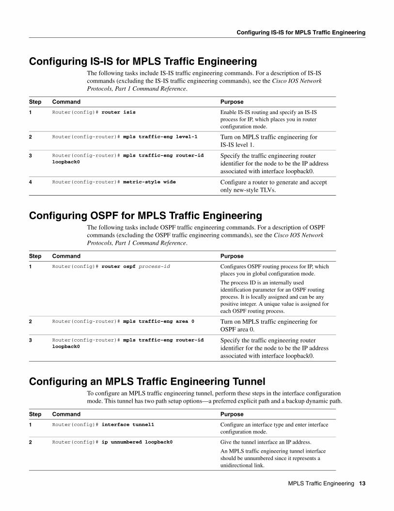
Configuring IS-IS for MPLS Traffic EngineeringThe following tasks include IS-IS traffic engineering commands. For a description of IS-IS commands (excluding the IS-IS traffic engineering commands), see the Cisco IOS Network Protocols, Part 1 Command Reference.
Configuring OSPF for MPLS Traffic EngineeringThe following tasks include OSPF traffic engineering commands. For a description of OSPF commands (excluding the OSPF traffic engineering commands), see the Cisco IOS Network Protocols, Part 1 Command Reference.
Configuring an MPLS Traffic Engineering TunnelTo configure an MPLS traffic engineering tunnel, perform these steps in the interface configuration mode. This tunnel has two path setup options—a preferred explicit path and a backup dynamic path.
Step Command Purpose
1 Router(config)# router isis Enable IS-IS routing and specify an IS-IS process for IP, which places you in router configuration mode.
2 Router(config-router)# mpls traffic-eng level-1 Turn on MPLS traffic engineering for IS-IS level 1.
3 Router(config-router)# mpls traffic-eng router-id loopback0
Specify the traffic engineering router identifier for the node to be the IP address associated with interface loopback0.
4 Router(config-router)# metric-style wide Configure a router to generate and accept only new-style TLVs.
Step Command Purpose
1 Router(config)# router ospf process-id Configures OSPF routing process for IP, which places you in global configuration mode.
The process ID is an internally used identification parameter for an OSPF routing process. It is locally assigned and can be any positive integer. A unique value is assigned for each OSPF routing process.
2 Router(config-router)# mpls traffic-eng area 0 Turn on MPLS traffic engineering for OSPF area 0.
3 Router(config-router)# mpls traffic-eng router-id loopback0
Specify the traffic engineering router identifier for the node to be the IP address associated with interface loopback0.
Step Command Purpose
1 Router(config)# interface tunnel1 Configure an interface type and enter interface configuration mode.
2 Router(config)# ip unnumbered loopback0 Give the tunnel interface an IP address.
An MPLS traffic engineering tunnel interface should be unnumbered since it represents a unidirectional link.
MPLS Traffic Engineering 13
Configuring an MPLS Traffic Engineering Tunnel to be Used by an IGP
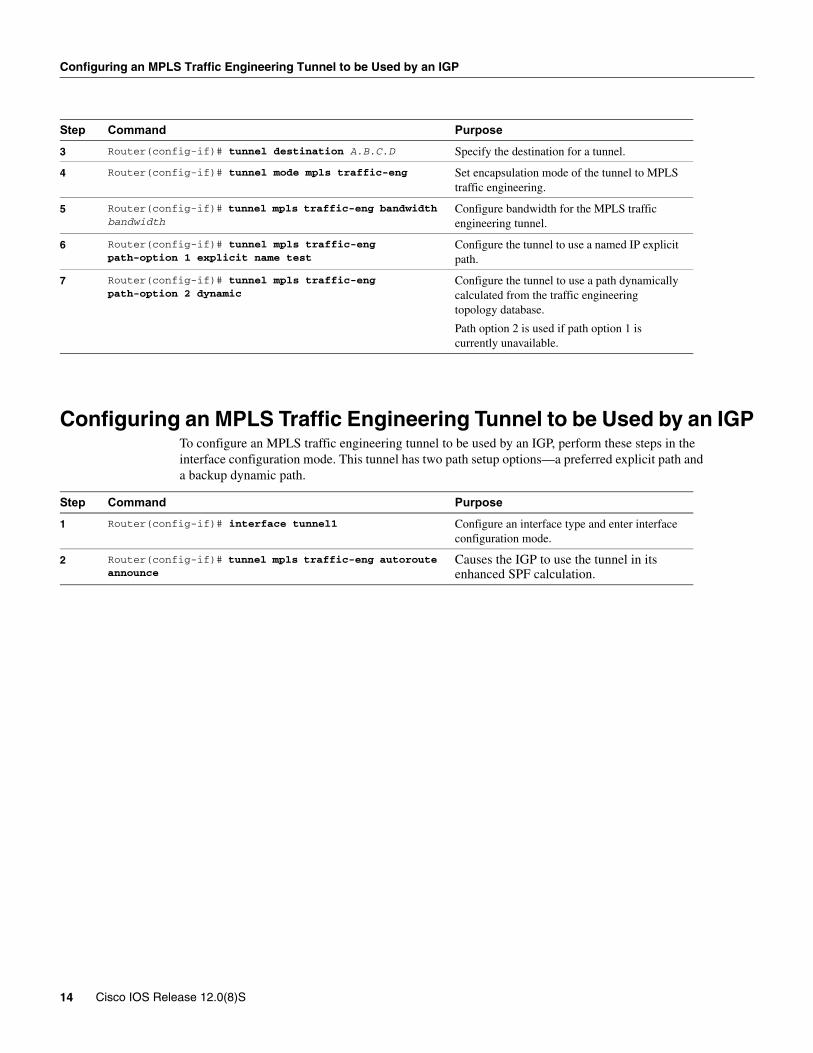
Configuring an MPLS Traffic Engineering Tunnel to be Used by an IGPTo configure an MPLS traffic engineering tunnel to be used by an IGP, perform these steps in the interface configuration mode. This tunnel has two path setup options—a preferred explicit path and a backup dynamic path.
3 Router(config-if)# tunnel destination A.B.C.D Specify the destination for a tunnel.
4 Router(config-if)# tunnel mode mpls traffic-eng Set encapsulation mode of the tunnel to MPLS traffic engineering.
5 Router(config-if)# tunnel mpls traffic-eng bandwidth bandwidth
Configure bandwidth for the MPLS traffic engineering tunnel.
6 Router(config-if)# tunnel mpls traffic-eng path-option 1 explicit name test
Configure the tunnel to use a named IP explicit path.
7 Router(config-if)# tunnel mpls traffic-eng path-option 2 dynamic
Configure the tunnel to use a path dynamically calculated from the traffic engineering topology database.
Path option 2 is used if path option 1 is currently unavailable.
Step Command Purpose
1 Router(config-if)# interface tunnel1 Configure an interface type and enter interface configuration mode.
2 Router(config-if)# tunnel mpls traffic-eng autoroute announce
Causes the IGP to use the tunnel in its enhanced SPF calculation.
Step Command Purpose
14 Cisco IOS Release 12.0(8)S
Configuring MPLS Traffic Engineering—IS-IS
Configuration ExamplesThis section provides the following configuration examples:
• Configuring IS-IS for MPLS Traffic Engineering
• Configuring OSPF for MPLS Traffic Engineering
• Configuring an MPLS Traffic Engineering Tunnel
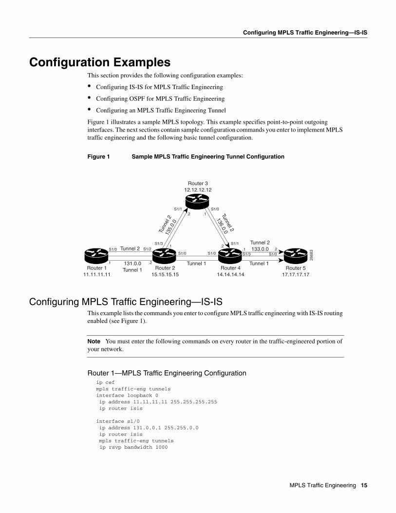
Figure 1 illustrates a sample MPLS topology. This example specifies point-to-point outgoing interfaces. The next sections contain sample configuration commands you enter to implement MPLS traffic engineering and the following basic tunnel configuration.
Figure 1 Sample MPLS Traffic Engineering Tunnel Configuration
Configuring MPLS Traffic Engineering—IS-ISThis example lists the commands you enter to configure MPLS traffic engineering with IS-IS routing enabled (see Figure 1).
Note You must enter the following commands on every router in the traffic-engineered portion of your network.
Router 1—MPLS Traffic Engineering Configurationip cefmpls traffic-eng tunnelsinterface loopback 0ip address 11.11.11.11 255.255.255.255ip router isis
interface s1/0ip address 131.0.0.1 255.255.0.0ip router isismpls traffic-eng tunnels
ip rsvp bandwidth 1000
131.0.0Tunnel 1Router 1
11.11.11.11Router 2
15.15.15.15Router 4
14.14.14.14
Router 312.12.12.12
Router 517.17.17.17
2668
3
Tunn
el 2
135.
0.0
Tunnel 2
136.0.0
Tunnel 1 Tunnel 1.1 .2
S1/0 S1/2
S1/1
S1/3
S1/0
S1/1
.2 .1
.1 .2
S1/0 S1/0.1 .2
Tunnel 2133.0.0
S1/3 S1/0Tunnel 2
MPLS Traffic Engineering 15
Configuration Examples
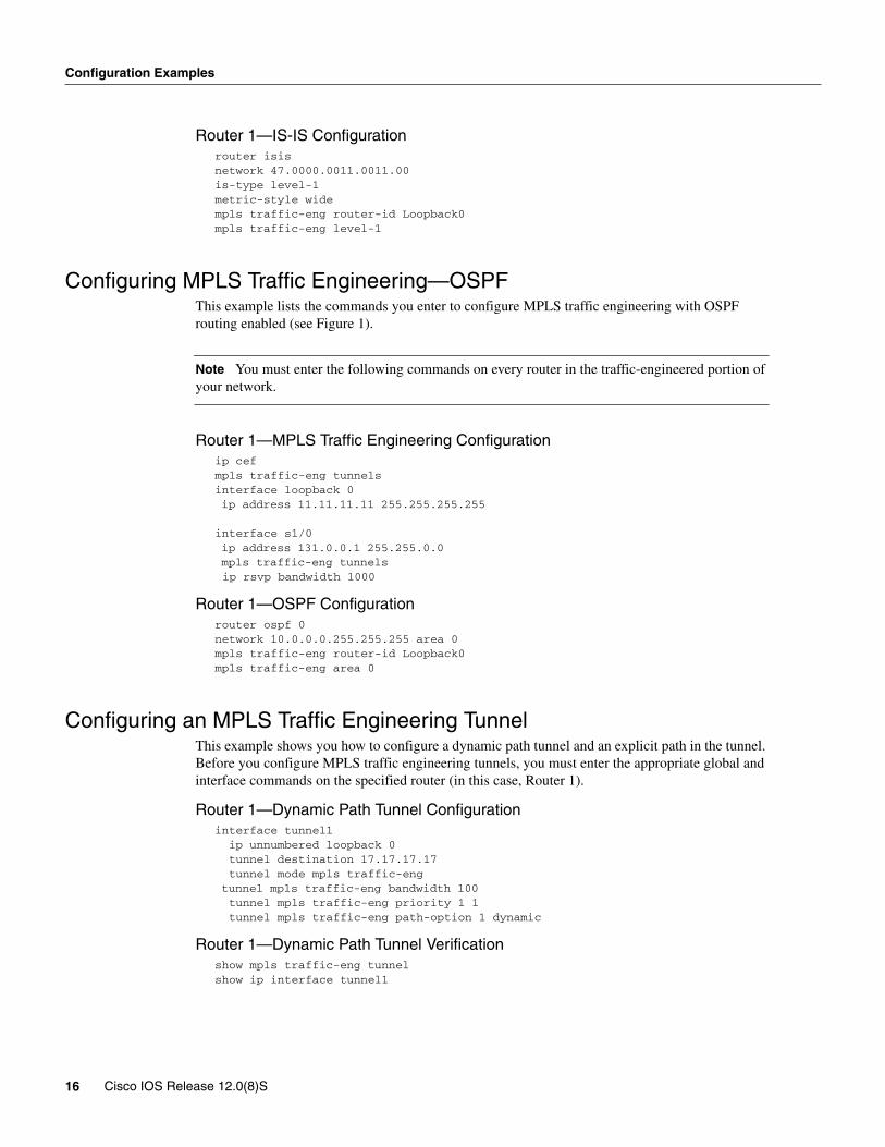
Router 1—IS-IS Configurationrouter isisnetwork 47.0000.0011.0011.00is-type level-1metric-style widempls traffic-eng router-id Loopback0mpls traffic-eng level-1
Configuring MPLS Traffic Engineering—OSPFThis example lists the commands you enter to configure MPLS traffic engineering with OSPF routing enabled (see Figure 1).
Note You must enter the following commands on every router in the traffic-engineered portion of your network.
Router 1—MPLS Traffic Engineering Configurationip cefmpls traffic-eng tunnelsinterface loopback 0ip address 11.11.11.11 255.255.255.255
interface s1/0ip address 131.0.0.1 255.255.0.0mpls traffic-eng tunnels
ip rsvp bandwidth 1000
Router 1—OSPF Configurationrouter ospf 0network 10.0.0.0.255.255.255 area 0mpls traffic-eng router-id Loopback0mpls traffic-eng area 0
Configuring an MPLS Traffic Engineering TunnelThis example shows you how to configure a dynamic path tunnel and an explicit path in the tunnel. Before you configure MPLS traffic engineering tunnels, you must enter the appropriate global and interface commands on the specified router (in this case, Router 1).
Router 1—Dynamic Path Tunnel Configurationinterface tunnel1 ip unnumbered loopback 0 tunnel destination 17.17.17.17 tunnel mode mpls traffic-engtunnel mpls traffic-eng bandwidth 100 tunnel mpls traffic-eng priority 1 1 tunnel mpls traffic-eng path-option 1 dynamic
Router 1—Dynamic Path Tunnel Verificationshow mpls traffic-eng tunnel show ip interface tunnel1
16 Cisco IOS Release 12.0(8)S

Configuring Enhanced SPF Routing over a Tunnel
Router 1—Explicit Path Configurationip explicit-path identifier 1 next-address 131.0.0.1 next-address 135.0.0.1 next-address 136.0.0.1 next-address 133.0.0.1
Router 1—Explicit Path Tunnel ConfigurationThe next section creates a tunnel that uses an explicit path.
interface tunnel2 ip unnumbered loopback 0 tunnel destination 17.17.17.17 tunnel mode mpls traffic-engtunnel mpls traffic-eng bandwidth 100 tunnel mpls traffic-eng priority 1 1 tunnel mpls traffic-eng path-option 1 explicit identifier 1
Router 1—Explicit Path Tunnel VerifcationThis section includes the commands that verify that the tunnel is up.
show mpls traffic-eng tunnel show ip interface tunnel2
Configuring Enhanced SPF Routing over a TunnelThis section includes the commands that cause the tunnel to be considered by the IGP’s enhanced SPF calculation which installs routes over the tunnel for appropriate network prefixes.
Router 1—IGP Enhanced SPF Consideration Configurationinterface tunnel1tunnel mpls traffic-eng autoroute announce
Router 1—Route and Traffic VerificationThis section includes the commands that verify that the tunnel is up and that the traffic is routed through the tunnel.
show traffic-eng tunnel tunnel1 briefshow ip route 17.17.17.17show mpls traffic-eng autorouteping 17.17.17.17show interface tunnel1 accountingshow interface s1/0 accounting
MPLS Traffic Engineering 17

Command Reference
Command ReferenceThis section documents new or modified commands. All other commands used with this feature are documented in the Cisco IOS Release 12.0 command references.
• append-after
• index
• ip explicit-path
• list
• metric-style narrow
• metric-style transition
• metric-style wide
• mpls traffic-eng
• mpls traffic-eng area
• mpls traffic-eng administrative-weight
• mpls traffic-eng attribute-flags
• mpls traffic-eng flooding thresholds
• mpls traffic-eng link timers bandwidth-hold
• mpls traffic-eng link timers bandwidth-hold
• mpls traffic-eng link timers periodic-flooding
• mpls traffic-eng reoptimize timers frequency
• mpls traffic-eng router-id
• mpls traffic-eng tunnels (configuration)
• mpls traffic-eng tunnels (interface)
• mpls traffic-eng tunnels (configuration)
• show ip explicit-paths
• show ip ospf database opaque-area
• show ip rsvp host
• show isis database verbose
• show isis mpls traffic-eng adjacency-log
• show isis mpls traffic-eng advertisements
• show isis mpls traffic-eng tunnel
• show mpls traffic-eng autoroute
• show mpls traffic-eng link-management admission-control
• show mpls traffic-eng link-management advertisements
• show mpls traffic-eng link-management bandwidth-allocation
• show mpls traffic-eng link-management igp-neighbors
• show mpls traffic-eng link-management interfaces
18 Cisco IOS Release 12.0(8)S
Configuring Enhanced SPF Routing over a Tunnel
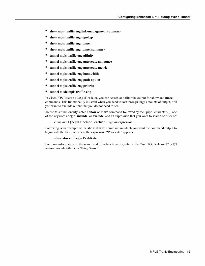
• show mpls traffic-eng link-management summary
• show mpls traffic-eng topology
• show mpls traffic-eng tunnel
• show mpls traffic-eng tunnel summary
• tunnel mpls traffic-eng affinity
• tunnel mpls traffic-eng autoroute announce
• tunnel mpls traffic-eng autoroute metric
• tunnel mpls traffic-eng bandwidth
• tunnel mpls traffic-eng path-option
• tunnel mpls traffic-eng priority
• tunnel mode mpls traffic-eng
In Cisco IOS Release 12.0(1)T or later, you can search and filter the output for show and more commands. This functionality is useful when you need to sort through large amounts of output, or if you want to exclude output that you do not need to see.
To use this functionality, enter a show or more command followed by the “pipe” character (|), one of the keywords begin, include, or exclude, and an expression that you want to search or filter on:
command | {begin | include | exclude} regular-expression
Following is an example of the show atm vc command in which you want the command output to begin with the first line where the expression “PeakRate” appears:
show atm vc | begin PeakRate
For more information on the search and filter functionality, refer to the Cisco IOS Release 12.0(1)T feature module titled CLI String Search.
MPLS Traffic Engineering 19
append-after
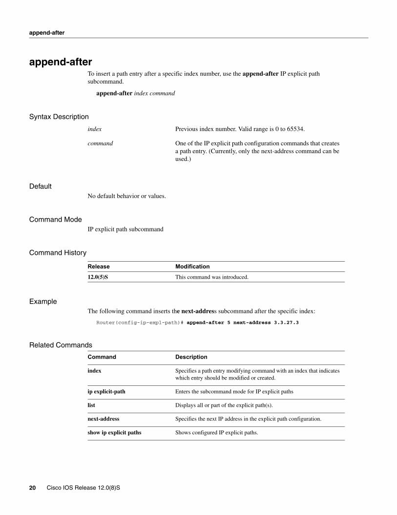
append-afterTo insert a path entry after a specific index number, use the append-after IP explicit path subcommand.
append-after index command
Syntax Description
DefaultNo default behavior or values.
Command ModeIP explicit path subcommand
Command History
ExampleThe following command inserts the next-address subcommand after the specific index:
Router(config-ip-expl-path)# append-after 5 next-address 3.3.27.3
Related Commands
index Previous index number. Valid range is 0 to 65534.
command One of the IP explicit path configuration commands that creates a path entry. (Currently, only the next-address command can be used.)
Release Modification
12.0(5)S This command was introduced.
Command Description
index Specifies a path entry modifying command with an index that indicates which entry should be modified or created.
ip explicit-path Enters the subcommand mode for IP explicit paths
list Displays all or part of the explicit path(s).
next-address Specifies the next IP address in the explicit path configuration.
show ip explicit paths Shows configured IP explicit paths.
20 Cisco IOS Release 12.0(8)S

index
indexTo insert or modify a path entry at a specific index, use the index IP explicit path subcommand.
index index command
Syntax Description
DefaultNo default behavior or values.
Command ModeIP explicit path subcommand
Command History
ExampleThe following command specifies where the next-address command should be inserted in the list:
Router(cfg-ip-expl-path)#index 6 next-address 3.3.29.3Explicit Path identifier 6: 6: next-address 3.3.29.3
Related Commands
index Specifies entry index number. Valid range is 0 to 65534.
command One of the IP explicit path configuration commands that creates or modifies a path entry. (Currently, only the next-address command can be used.)
Release Modification
12.0(5)S This command was introduced.
Command Description
append-after Similar to the index subcommand, except that the new path entry is inserted after the specified index number. Renumbering of commands may be performed as a result.
ip explicit-path Enters the subcommand mode for IP explicit paths
list Displays all or part of the explicit path(s).
next-address Specifies the next IP address in the explicit path.
show ip explicit paths Shows configured IP explicit paths.
MPLS Traffic Engineering 21

ip explicit-path
ip explicit-pathTo enter the subcommand mode for IP explicit paths to create or modify the named path, use the ip explicit-path command. An IP explicit path is a list of IP addresses, each representing a node or link in the explicit path.
ip explicit-path {name WORD | identifier number} [{enable | disable}]
Syntax Description
DefaultEnabled
Command ModeConfiguration
Command History
ExampleThe following command enters the explicit path subcommand mode for IP explicit paths and creates a path with the number 500.
Router(config)# ip explicit-path identifier 500Router(config-ip-expl-path)
name Word Specifies explicit path by name.
identifier number Specifies explicit path by number. You can specify a number from 1 to 65535.
enable Sets the state of the path to be enabled.
disable Prevents the path from being used for routing while it is being configured.
Release Modification
12.0(5)S This command was introduced.
22 Cisco IOS Release 12.0(8)S

ip explicit-path
Related Commands
Command Description
append-after Similar to the index subcommand, except that the new path entry is inserted after the specified index number. Renumbering of commands may be performed as a result.
index Specifies a path entry modifying command with an index that indicates which entry should be modified or created.
list Displays all or part of the explicit path(s).
next-address Specifies the next IP address in the explicit path.
show ip explicit paths Shows configured IP explicit paths.
MPLS Traffic Engineering 23
list
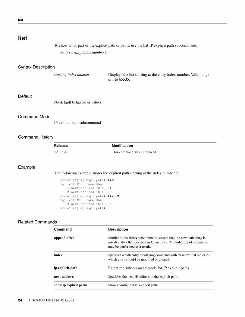
listTo show all or part of the explicit path or paths, use the list IP explicit path subcommand.
list [{starting index number}]
Syntax Description
DefaultNo default behavior or values.
Command ModeIP explicit path subcommand
Command History
ExampleThe following example shows the explicit path starting at the index number 2.
Router(cfg-ip-expl-path# listExplicit Path name Joe: 1:next-address 10.0.0.1 2:next-address 10.0.0.2Router(cfg-ip-expl-path# list 2Explicit Path name Joe: 2:next-address 10.0.0.2Router(cfg-ip-expl-path#
Related Commands
starting index number Displays the list starting at the entry index number. Valid range is 1 to 65535.
Release Modification
12.0(5)S This command was introduced.
Command Description
append-after Similar to the index subcommand, except that the new path entry is inserted after the specified index number. Renumbering of commands may be performed as a result.
index Specifies a path entry modifying command with an index that indicates which entry should be modified or created.
ip explicit-path Enters the subcommand mode for IP explicit paths
next-address Specifies the next IP address in the explicit path.
show ip explicit paths Shows configured IP explicit paths.
24 Cisco IOS Release 12.0(8)S

metric-style narrow
metric-style narrowTo configure a router running IS-IS to generate and accept old-style TLVs (TLV stands for type, length, and value object), use the metric-style narrow command.
metric-style narrow [transition] [{level-1 | level-2 | level-1-2}]
Syntax Description
DefaultIS-IS traffic engineering extensions include new-style TLVs with wider metric fields than old-style TLVs. By default, the MPLS traffic engineering image generates old-style TLVs only. To do MPLS traffic engineering, a router needs to generate new-style TLVs.
Command ModeRouter configuration
Command History
ExampleThe following command instructs the router to generate and accept old-style TLVs on router level 1.
Router(config)# metric-style narrow level-1
Related Commands
transition (Optional) Instructs the router to use both old and new style TLVs.
level-1 Enables this command on routing level 1.
level-2 Enables this command on routing level 2.
level-1-2 Enables this command on routing levels 1 and 2.
Release Modification
12.0(5)S This command was introduced.
Command Description
metric-style wide Configures a router to generate and accept only new-style TLVs.
metric-style transition Configures a router to generate both old-style and new-style TLVs.
MPLS Traffic Engineering 25
metric-style transition
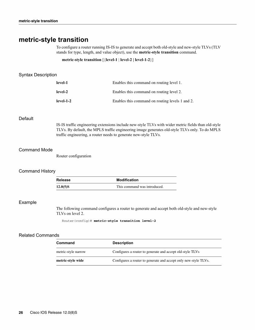
metric-style transitionTo configure a router running IS-IS to generate and accept both old-style and new-style TLVs (TLV stands for type, length, and value object), use the metric-style transition command.
metric-style transition [{level-1 | level-2 | level-1-2}]
Syntax Description
DefaultIS-IS traffic engineering extensions include new-style TLVs with wider metric fields than old-style TLVs. By default, the MPLS traffic engineering image generates old-style TLVs only. To do MPLS traffic engineering, a router needs to generate new-style TLVs.
Command ModeRouter configuration
Command History
ExampleThe following command configures a router to generate and accept both old-style and new-style TLVs on level 2.
Router(config)# metric-style transition level-2
Related Commands
level-1 Enables this command on routing level 1.
level-2 Enables this command on routing level 2.
level-1-2 Enables this command on routing levels 1 and 2.
Release Modification
12.0(5)S This command was introduced.
Command Description
metric-style narrow Configures a router to generate and accept old-style TLVs
metric-style wide Configures a router to generate and accept only new-style TLVs.
26 Cisco IOS Release 12.0(8)S
metric-style wide
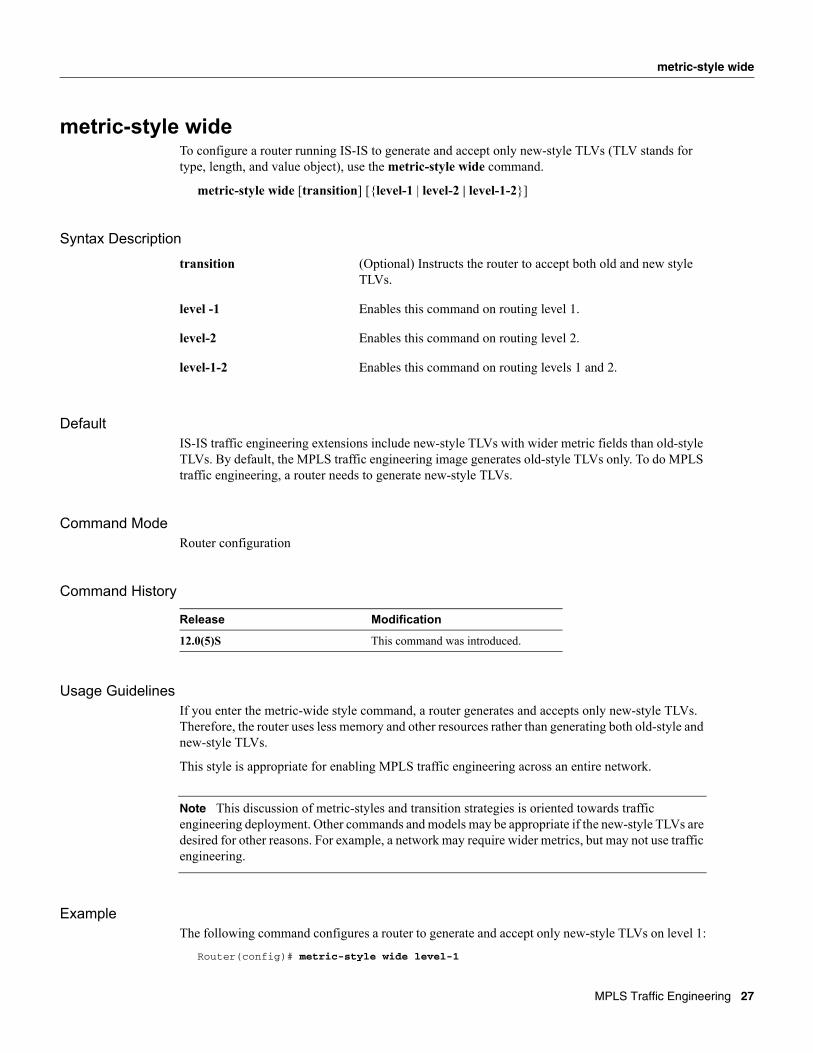
metric-style wideTo configure a router running IS-IS to generate and accept only new-style TLVs (TLV stands for type, length, and value object), use the metric-style wide command.
metric-style wide [transition] [{level-1 | level-2 | level-1-2}]
Syntax Description
DefaultIS-IS traffic engineering extensions include new-style TLVs with wider metric fields than old-style TLVs. By default, the MPLS traffic engineering image generates old-style TLVs only. To do MPLS traffic engineering, a router needs to generate new-style TLVs.
Command ModeRouter configuration
Command History
Usage GuidelinesIf you enter the metric-wide style command, a router generates and accepts only new-style TLVs. Therefore, the router uses less memory and other resources rather than generating both old-style and new-style TLVs.
This style is appropriate for enabling MPLS traffic engineering across an entire network.
Note This discussion of metric-styles and transition strategies is oriented towards traffic engineering deployment. Other commands and models may be appropriate if the new-style TLVs are desired for other reasons. For example, a network may require wider metrics, but may not use traffic engineering.
ExampleThe following command configures a router to generate and accept only new-style TLVs on level 1:
Router(config)# metric-style wide level-1
transition (Optional) Instructs the router to accept both old and new style TLVs.
level -1 Enables this command on routing level 1.
level-2 Enables this command on routing level 2.
level-1-2 Enables this command on routing levels 1 and 2.
Release Modification
12.0(5)S This command was introduced.
MPLS Traffic Engineering 27

metric-style wide
Related CommandsCommand Description
metric-style narrow Configures a router to generate and accept old-style TLVs
metric-style transition Configures a router to generate and accept both old-style and new-style TLVs
28 Cisco IOS Release 12.0(8)S

mpls traffic-eng
mpls traffic-eng To configure a router running IS-IS to flood MPLS traffic engineering link information into the indicated IS-IS level, use the mpls traffic-eng command.
mpls traffic-eng isis-level {level-1 | level-2}
Syntax Description
DefaultFlooding is disabled.
Command Mode Router configuration
Command History
Usage GuidelinesThis command appears as part of the routing protocol tree, and causes link resource information (for instance, bandwidth available) for appropriately configured links to be flooded in the IS-IS link state database.
ExampleThe following command turns on MPLS traffic engineering for IS-IS Level 1.
Router(router-config)# mpls traffic-eng isis-level level 1
Related Commands
level-1 Flood MPLS traffic engineering link information into IS-IS level 1.
level-2 Flood MPLS traffic engineering link information into IS-IS level 2.
Release Modification
12.0(5)S This command was introduced.
Command Description
mpls traffic-eng router-id Specifies the traffic engineering router identifier for the node to be the IP address associated with the given interface.
MPLS Traffic Engineering 29
mpls traffic-eng area
mpls traffic-eng areaTo configure a router running OSPF MPLS to flood traffic engineering for the indicated OSPF area, use the mpls traffic-eng area command.
mpls traffic-eng area 1-n
Syntax Description
DefaultNo default behavior or values
Command Mode Router configuration
Command History
Usage GuidelinesThis command is included in the routing protocol configuration tree, and is supported for both OSPF and IS-IS. The command only affects the operation of MPLS traffic engineering if MPLS traffic engineering is enabled for that routing protocol instance.
Currently, only a single level may be enabled for traffic engineering.
1-n The OSPF area on which MPLS traffic engineering is enabled.
Release Modification
12.0(5)S This command was introduced.
30 Cisco IOS Release 12.0(8)S

mpls traffic-eng administrative-weight
mpls traffic-eng administrative-weightTo override the Internet Gateway Protocol’s (IGP) administrative weight (cost) of the link, use the mpls traffic-eng administrative-weight command. To disable this feature, use the no form of this command.
mpls traffic-eng administrative-weight weightno mpls traffic-eng administrative-weight weight
Syntax Description
DefaultMatches IGP cost
Command Mode Interface configuration
Command History
ExampleThe following example overrides the IGP’s cost of the link and sets the cost to 20.
Router(config_if)# mpls traffic-eng administrative-weight 20
Related Commands
weight Cost of the link.
Release Modification
12.0(5)S This command was introduced.
Command Description
mpls traffic-eng attribute-flags Sets the user-specified attribute-flags for an interface.
MPLS Traffic Engineering 31

mpls traffic-eng attribute-flags
mpls traffic-eng attribute-flags To set the user-specified attribute-flags for the interface, use the mpls traffic-eng attribute-flags command. The interface is flooded globally so that it can be used as a tunnel head-end path selection criterion. To disable this feature, use the no form of this command.
mpls traffic-eng attribute-flags attributes no mpls traffic-eng attribute flags
Syntax Description
DefaultDefault is 0x0.
Command Mode Interface configuration
Command History
Usage GuidelinesThe purpose of this command is to assign attributes to a link in order to cause tunnels with matching attributes (as represented by their affinity bits) to prefer this link over others which do not match.
ExampleThe following example sets the attribute flags:
Router(config-if)# mpls traffic-eng attribute-flags 0x0101
Related Commands
attributes Link attributes to be compared with a tunnel’s affinity bits during path selection.
Range is 0x0 to 0xFFFFFFFF, representing 32 attributes (bits) where the value of an attribute is either 0 or 1.
Release Modification
12.0(5)S This command was introduced.
Command Description
tunnel mpls traffic-eng affinity Configures affinity (the properties the tunnel requires in its links) for an MPLS traffic engineering tunnel.
mpls traffic-eng administrative weight Overrides the Interior Gateway Protocol’s (IGP) administrative weight of the link.
32 Cisco IOS Release 12.0(8)S

mpls traffic-eng flooding thresholds
mpls traffic-eng flooding thresholdsTo set a link’s reserved bandwidth thresholds, use the mpls traffic-eng flooding thresholds commands. If a bandwidth threshold is crossed, the link’s bandwidth information is immediately flooded throughout the network. To return to the default settings, use the no form of this command.
mpls traffic-eng flooding thresholds {down | up} percent [percent...]no mpls traffic-eng flooding thresholds {down | up} percent [percent...]
Syntax Description
DefaultThe default for down is
100, 99, 98, 97, 96, 95, 90, 85, 80, 75, 60, 45, 30, 15.
The default for up is
15, 30, 45, 60, 75, 80, 85, 90, 95, 97, 98, 99, 100.
Command ModeInterface configuration
Command History
Usage GuidelinesWhen a threshold is crossed, MPLS traffic engineering link management advertises updated link information. Similarly, if no thresholds are crossed, changes may be flooded periodically unless periodic flooding has been disabled.
ExampleThe following example sets the link’s reserved bandwidth for decreased resource availability (down) and for increased resource availability (up) thresholds.
Router(config-if)# mpls traffic-eng flooding thresholds down 100 75 25Router(config-if)# mpls traffic-eng flooding thresholds up 25 50 100
down Sets the thresholds for decreased resource availability. The range is 0 to 99 percent.
up Sets the thresholds for increased resource availability. The range is 1 to 100 percent.
percent [percent] Specifies the bandwidth threshold level.
Release Modification
12.0(5)S This command was introduced.
MPLS Traffic Engineering 33

mpls traffic-eng flooding thresholds
Related Commands
Command Description
mpls traffic-eng link-timers periodic-flooding Sets the length of the interval used for periodic flooding.
show mpls traffic-eng link-management advertisements Shows local link information currently being flooded by MPLS traffic engineering link management into the global traffic engineering topology.
show mpls traffic-eng link-management bandwidth-allocation Shows current local link information.
34 Cisco IOS Release 12.0(8)S
mpls traffic-eng link timers bandwidth-hold
mpls traffic-eng link timers bandwidth-holdTo set the length of time that bandwidth is "held" for a RSVP PATH (Set Up) message while waiting for the corresponding RSVP RESV message to come back, use the mpls traffic-eng link timers bandwidth-hold command.
mpls traffic-eng link timers bandwidth-hold hold-time
Syntax Description
Default15 seconds
Command Mode Configuration
Command History
ExampleThe following example sets the length of time that bandwidth is held to 10 seconds.
Router(config)# mpls traffic-eng link-management timers bandwidth-hold 10
Related Command
hold-time Sets the length of time that bandwidth can be held. The range is from 1 to 300 seconds.
Release Modification
12.0(5)S This command was introduced.
Command Description
show mpls traffic-eng link-management bandwidth-allocation
Shows current local link information.
MPLS Traffic Engineering 35
mpls traffic-eng link timers periodic-flooding
mpls traffic-eng link timers periodic-floodingTo set the length of the interval used for periodic flooding, use the mpls traffic-eng link timers periodic-flooding command.
mpls traffic-eng link timers periodic-flooding interval
Syntax Description
Default3 minutes
Command Mode Configuration
Command History
Usage GuidelinesUse this command to set the length of the interval used for periodic flooding to advertise link state information changes that do not trigger immediate action (for example, a change to the amount of bandwidth allocated that does not cross a threshold).
ExampleThe following example sets the interval length for periodic flooding to advertise flooding changes to 120 seconds.
Router(config)# mpls traffic-eng timers periodic-flooding 120
Related Commands
interval Length of interval used for periodic flooding (in seconds). The range is 0-3600. If you set this value to 0, you turn off periodic flooding. If you set this value anywhere in the range from 1 to 29, it is treated at 30.
Release Modification
12.0(5)S This command was introduced.
Command Description
mpls traffic-eng flooding thresholds Sets a link’s reserved bandwidth threshold.
36 Cisco IOS Release 12.0(8)S

mpls traffic-eng reoptimize timers frequency
mpls traffic-eng reoptimize timers frequencyTo control the frequency at which tunnels with established LSPs are checked for better LSPs, use the mpls traffic-eng reoptimize timers frequency command.
mpls traffic-eng reoptimize timers frequency seconds
Syntax Description
Default3600 seconds (1 hour) with a range of 0 to 604800 seconds (1 week).
Command Mode Configuration
Command History
Usage GuidelinesA device with traffic engineering tunnels periodically examines tunnels with established LSPs to see if better LSPs are available. If a better LSP seems to be available, the device attempts to signal the better LSP and, if successful, replaces the old and inferior LSP with the new and better LSP.
ExampleThe following example sets the reoptimization frequency to one day.
Router(config)# mpls traffic-eng reoptimize timers frequency 86400
Related Commands
seconds Sets the frequency of reoptimization, in seconds. A value of 0 disables reoptimization.
Release Modification
12.0(5)S This command was introduced.
Command Description
mpls traffic-eng reoptimize (exec) Does a reoptimization check now.
tunnel mpls traffic-eng lockdown Does not do a reoptimization check on this tunnel.
MPLS Traffic Engineering 37
mpls traffic-eng router-id
mpls traffic-eng router-idTo specify the traffic engineering router identifier for the node to be the IP address associated with the given interface, use the mpls traffic-eng router-id command.
mpls traffic-eng router-id interface
Syntax Description
DefaultNo default behavior or values.
Command Mode Router configuration
Command History
Usage GuidelinesThis router identifier acts as a stable IP address for the traffic engineering configuration. This stable IP address is flooded to all nodes. For all traffic engineering tunnels originating at other nodes and ending at this node, the tunnel destination must be set to the destination node's traffic engineering router identifier, since that is the address the traffic engineering topology database at the tunnel head uses for its path calculation.
Related Commands
interface
Release Modification
12.0(5)S This command was introduced.
Command Description
mpls traffic-eng Turn on flooding of MPLS traffic-engineering link information into the indicated IGP level/area.
38 Cisco IOS Release 12.0(8)S

mpls traffic-eng tunnels (configuration)
mpls traffic-eng tunnels (configuration)To enable MPLS traffic engineering tunneling signalling on a device, use the mpls traffic-eng tunnels command.
mpls traffic-eng tunnelsno mpls traffic-eng tunnels
Syntax DescriptionThis command has no arguments or keywords.
DefaultThe feature is disabled.
Command Mode Configuration
Command History
Usage GuidelinesEnables the MPLS traffic-engineering feature on a device. To use the feature, MPLS traffic engineering must also be enabled on the desired interfaces.
ExampleThe following command turns on the MPLS traffic engineering feature for a device:
Router(config)# mpls traffic-eng tunnels
Related Commands
Release Modification
12.0(5)S This command was introduced.
Command Description
mpls traffic-eng tunnels (interface) Enables MPLS traffic engineering tunnel signalling on an interface.
MPLS Traffic Engineering 39
mpls traffic-eng tunnels (interface)
mpls traffic-eng tunnels (interface)To enable MPLS traffic engineering tunnel signalling on an interface, assuming it is enabled for the device, use the mpls traffic-eng tunnels command.
mpls traffic-eng tunnelsno mpls traffic-eng tunnels
Syntax DescriptionThis command has no arguments or keywords.
DefaultThe feature is disabled on all interfaces.
Command Mode Interface configuration
Command History
Usage GuidelinesEnables the MPLS traffic-engineering feature on the interface. To use the feature, MPLS traffic engineering must also be enabled on the device. An enabled interface has its resource information flooded into the appropriate IGP link state database, and accepts traffic engineering tunnel signalling requests.
ExampleThe following commands turns on MPLS traffic engineering on interface Ethernet0/0.
Router# configure terminalRouter(config)# interface Ethernet0/0Router(config-if)# mpls traffic-eng tunnels
Related Commands
Release Modification
12.0(5)S This command was introduced.
Command Description
mpls traffic-eng tunnels (configuration) Enables MPLS traffic engineering tunneling signalling on a device.
40 Cisco IOS Release 12.0(8)S
next-address
next-addressTo specify the next IP address in the explicit path, use the next-address IP explicit path subcommand.
next-address A.B.C.D
Syntax Description
DefaultNo default behavior or values.
Command ModeIP explicit path subcommand
Command History
ExampleThe following commands assign the number 60 to the IP explicit path, set the state of the path to be enabled, and specify 3.3.27.3 as the next IP address in the list of IP addresses.
Router# configure terminal
Enter configuration commands, one per line. End with CNTL/Z.Router(config)# mpls traffic-eng tunnelsRouter(config)# ip explicit-path identifier 60 enableRouter(cfg-ip-expl-path)# next-address 3.3.27.3Explicit Path identifier 60: 1: next-address 3.3.27.3
A.B.C.D Specifies the IP address in the explicit path.
Release Modification
12.0(5)S This command was introduced.
MPLS Traffic Engineering 41

next-address
Related Commands
Command Description
append-after Similar to the index subcommand, except that the new path entry is inserted after the specified index number. Renumbering of commands may be performed as a result.
index Specifies a path entry modifying command with an index that indicates which entry should be modified or created.
ip explicit-path Enters the subcommand mode for IP explicit paths.
list Displays all or part of the explicit path(s).
show ip explicit paths Shows configured IP explicit paths.
42 Cisco IOS Release 12.0(8)S

show ip explicit-paths
show ip explicit-pathsTo enter the subcommand mode for IP explicit paths to create or modify the named path, use the show explicit-paths EXEC command. An IP explicit path is a list of IP addresses, each representing a node or link in the explicit path.
show ip explicit-paths [{name Word | identifier number}] [detail]
Syntax Description
DefaultNo default behavior or values.
Command Mode EXEC
Command History
ExampleThe following example shows output from the show ip explicit-paths command:
Router# show ip explicit-paths
PATH 200 (strict source route, path complete, generation 6) 1: next-address 3.3.28.3 2: next-address 3.3.27.3
Table 1 lists the fields displayed in this example.
Table 1 Show IP Explicit-Paths Field Descriptions
name Word Specifies explicit path by name.
identifier number Specifies explicit path by number.
detail (Optional) Display information in long form.
Release Modification
12.0(5)S This command was introduced.
Field Description
PATH Path name or number, followed by path status.
1: next-address The first IP address in the path.
2. next-address The second IP address in the path.
MPLS Traffic Engineering 43

show ip explicit-paths
Related Commands
Command Description
append-after Similar to the index subcommand, except that the new path entry is inserted after the specified index number. Renumbering of commands may be performed as a result.
index Specifies a path entry modifying command with an index that indicates which entry should be modified or created.
ip explicit-paths Enters the subcommand mode for IP explicit paths.
list Displays all or part of the explicit path(s).
next-address Specifies a next-address subcommand with an index that specifies where the command should be inserted in the list.
44 Cisco IOS Release 12.0(8)S
show ip ospf database opaque-area
show ip ospf database opaque-areaTo display lists of information related to traffic engineering opaque LSAs, also known as Type-10 Opaque Link Area Link States, use the show ip ospf database opaque-area command.
show ip ospf database opaque-area
Syntax DescriptionThis command has no arguments or keywords.
DefaultNo default behavior or values.
Command Mode EXEC
Command History
Usage GuidelinesWhen you display the show ip ospf database opaque-area command output, the information includes a “Link State ID” that reads 168.x.x.0 where 168 is the opaque LSA type and x.x. is the low 16 bits of the OSPF router identifier.
Release Modification
12.0(6)T This command was introduced.
MPLS Traffic Engineering 45
show ip ospf database opaque-area
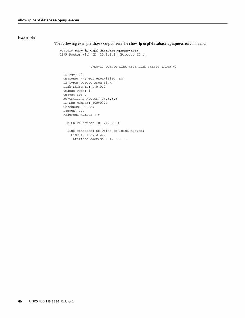
ExampleThe following example shows output from the show ip ospf database opaque-area command:
Router# show ip ospf database opaque-areaOSPF Router with ID (25.3.3.3) (Process ID 1) Type-10 Opaque Link Area Link States (Area 0) LS age: 12 Options: (No TOS-capability, DC) LS Type: Opaque Area Link Link State ID: 1.0.0.0 Opaque Type: 1 Opaque ID: 0 Advertising Router: 24.8.8.8 LS Seq Number: 80000004 Checksum: 0xD423 Length: 132 Fragment number : 0 MPLS TE router ID: 24.8.8.8 Link connected to Point-to-Point network Link ID : 26.2.2.2 Interface Address : 198.1.1.1
46 Cisco IOS Release 12.0(8)S
show ip rsvp host
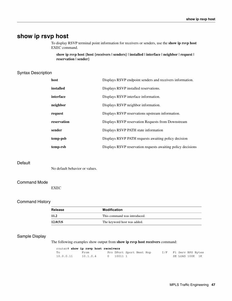
show ip rsvp hostTo display RSVP terminal point information for receivers or senders, use the show ip rsvp host EXEC command.
show ip rsvp host {host {receivers | senders} | installed | interface | neighbor | request | reservation | sender}
Syntax Description
DefaultNo default behavior or values.
Command Mode EXEC
Command History
Sample DisplayThe following examples show output from show ip rsvp host receivers command:
router# show ip rsvp host receiversTo From Pro DPort Sport Next Hop I/F Fi Serv BPS Bytes10.0.0.11 10.1.0.4 0 10011 1 SE LOAD 100K 1K
host Displays RSVP endpoint senders and receivers information.
installed Displays RSVP installed reservations.
interface Displays RSVP interface information.
neighbor Displays RSVP neighbor information.
request Displays RSVP reservations upstream information.
reservation Displays RSVP reservation Requests from Downstream
sender Displays RSVP PATH state information
temp-psb Displays RSVP PATH requests awaiting policy decision
temp-rsb Displays RSVP reservation requests awaiting policy decisions
Release Modification
11.2 This command was introduced.
12.0(5)S The keyword host was added.
MPLS Traffic Engineering 47
show ip rsvp host
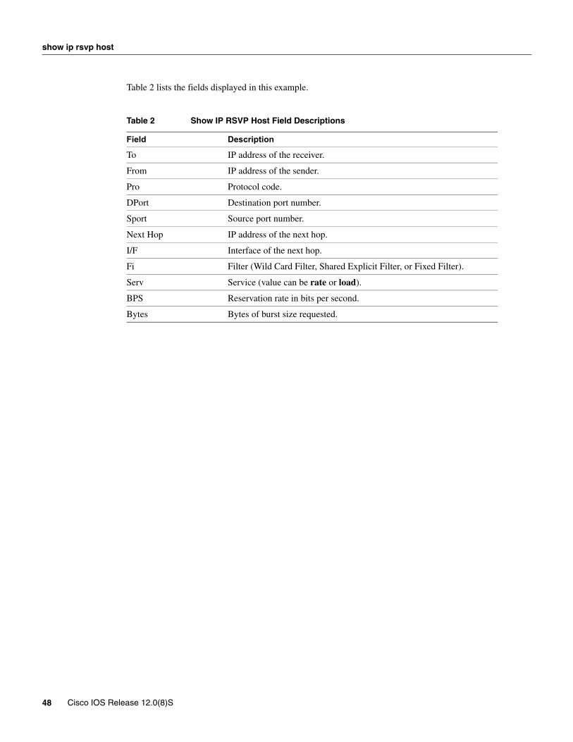
Table 2 lists the fields displayed in this example.
Table 2 Show IP RSVP Host Field Descriptions
Field Description
To IP address of the receiver.
From IP address of the sender.
Pro Protocol code.
DPort Destination port number.
Sport Source port number.
Next Hop IP address of the next hop.
I/F Interface of the next hop.
Fi Filter (Wild Card Filter, Shared Explicit Filter, or Fixed Filter).
Serv Service (value can be rate or load).
BPS Reservation rate in bits per second.
Bytes Bytes of burst size requested.
48 Cisco IOS Release 12.0(8)S

show isis database verbose
show isis database verboseTo display more information about the database, use the show isis database verbose EXEC command.
show isis database verbose
Syntax DescriptionThis command has no arguments or keywords.
DefaultNo default behavior or values.
Command Mode EXEC
Command History
Sample DisplayThe following example shows output from the show isis database verbose command:
Router# show isis database verbose
IS-IS Level-1 Link State DatabaseLSPID LSP Seq Num LSP Checksum LSP Holdtime ATT/P/OLdtp-5.00-00 * 0x000000E6 0xC9BB 1042 0/0/0 Area Address:49.0001 NLPID: 0xCC Hostname:dtp-5 Router ID: 5.5.5.5 IP Address: 172.21.39.5 Metric:10 IP 172.21.39.0/24dtp-5.00-01 * 0x000000E7 0xAB36 1065 0/0/0 Metric:10 IS-Extended dtp-5.01 Affinity:0x00000000 Interface IP Address:172.21.39.5 Physical BW:10000000 bits/sec Reservable BW:1166000 bits/sec BW Unreserved[0]: 1166000 bits/sec, BW Unreserved[1]: 1166000 bits/sec BW Unreserved[2]: 1166000 bits/sec, BW Unreserved[3]: 1166000 bits/sec BW Unreserved[4]: 1166000 bits/sec, BW Unreserved[5]: 1166000 bits/sec BW Unreserved[6]: 1166000 bits/sec, BW Unreserved[7]: 1153000 bits/sec Metric:0 ES dtp-5
Release Modification
12.0(5)S This command was introduced.
MPLS Traffic Engineering 49
show isis database verbose
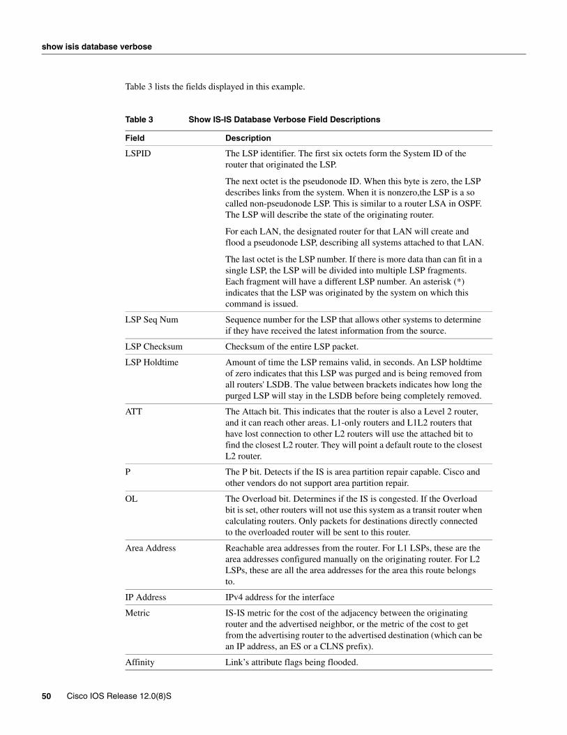
Table 3 lists the fields displayed in this example.
Table 3 Show IS-IS Database Verbose Field Descriptions
Field Description
LSPID The LSP identifier. The first six octets form the System ID of the router that originated the LSP.
The next octet is the pseudonode ID. When this byte is zero, the LSP describes links from the system. When it is nonzero,the LSP is a so called non-pseudonode LSP. This is similar to a router LSA in OSPF. The LSP will describe the state of the originating router.
For each LAN, the designated router for that LAN will create and flood a pseudonode LSP, describing all systems attached to that LAN.
The last octet is the LSP number. If there is more data than can fit in a single LSP, the LSP will be divided into multiple LSP fragments. Each fragment will have a different LSP number. An asterisk (*) indicates that the LSP was originated by the system on which this command is issued.
LSP Seq Num Sequence number for the LSP that allows other systems to determine if they have received the latest information from the source.
LSP Checksum Checksum of the entire LSP packet.
LSP Holdtime Amount of time the LSP remains valid, in seconds. An LSP holdtime of zero indicates that this LSP was purged and is being removed from all routers' LSDB. The value between brackets indicates how long the purged LSP will stay in the LSDB before being completely removed.
ATT The Attach bit. This indicates that the router is also a Level 2 router, and it can reach other areas. L1-only routers and L1L2 routers that have lost connection to other L2 routers will use the attached bit to find the closest L2 router. They will point a default route to the closest L2 router.
P The P bit. Detects if the IS is area partition repair capable. Cisco and other vendors do not support area partition repair.
OL The Overload bit. Determines if the IS is congested. If the Overload bit is set, other routers will not use this system as a transit router when calculating routers. Only packets for destinations directly connected to the overloaded router will be sent to this router.
Area Address Reachable area addresses from the router. For L1 LSPs, these are the area addresses configured manually on the originating router. For L2 LSPs, these are all the area addresses for the area this route belongs to.
IP Address IPv4 address for the interface
Metric IS-IS metric for the cost of the adjacency between the originating router and the advertised neighbor, or the metric of the cost to get from the advertising router to the advertised destination (which can be an IP address, an ES or a CLNS prefix).
Affinity Link’s attribute flags being flooded.
50 Cisco IOS Release 12.0(8)S

show isis database verbose
Physical BW Link’s bandwidth capacity (in bits per second).
Reservable BW Amount of reservable bandwidth on this link.
BW Unreserved Amount of bandwidth that is available for reservation.
MPLS Traffic Engineering 51

show isis mpls traffic-eng adjacency-log
show isis mpls traffic-eng adjacency-logTo display a log of 20 entries of MPLS traffic engineering IS-IS adjacency changes, use the show isis mpls traffic-eng adjacency-log EXEC command.
show isis mpls traffic-eng adjacency-log
Syntax DescriptionThis command has no arguments or keywords.
DefaultNo default behavior or values.
Command Mode EXEC
Command History
Sample DisplayThe following is sample output from the show isis mpls traffic-eng adjacency-log command:
Router# show isis mpls traffic-eng adjacency-log
IS-IS RRR logWhen Neighbor ID IP Address Interface Status Level04:52:52 0000.0024.0004.02 0.0.0.0 Et0/2 Up level-104:52:50 0000.0026.0001.00 170.1.1.2 PO1/0/0 Up level-104:52:37 0000.0024.0004.02 0.0.0.0 Et0/2 Up level-1
Table 4 lists the fields displayed in this example.
Table 4 Show IS-IS MPLS Traffic-Eng Adjacency-Log Field Descriptions
Release Modification
12.0(5)S This command was introduced.
Field Description
When The amount of time since the entry of the log has been recorded.
Neighbor ID Identification value of the neighbor.
IP Address Neighbor’s IPv4 address.
Interface Interface from which a neighbor is learned.
Status Up (active) or Down (disconnected)
Level Indication of routing level.
52 Cisco IOS Release 12.0(8)S
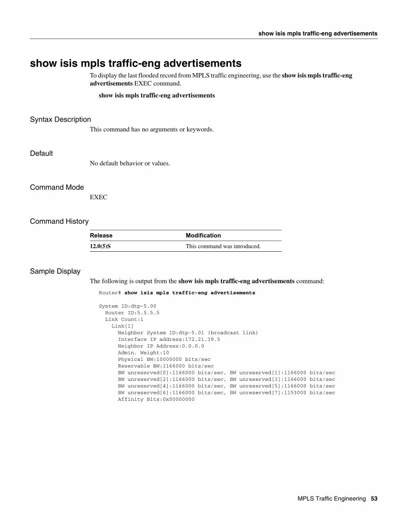
show isis mpls traffic-eng advertisements
show isis mpls traffic-eng advertisementsTo display the last flooded record from MPLS traffic engineering, use the show isis mpls traffic-eng advertisements EXEC command.
show isis mpls traffic-eng advertisements
Syntax DescriptionThis command has no arguments or keywords.
DefaultNo default behavior or values.
Command Mode EXEC
Command History
Sample DisplayThe following is output from the show isis mpls traffic-eng advertisements command:
Router# show isis mpls traffic-eng advertisements
System ID:dtp-5.00 Router ID:5.5.5.5 Link Count:1 Link[1] Neighbor System ID:dtp-5.01 (broadcast link) Interface IP address:172.21.39.5 Neighbor IP Address:0.0.0.0 Admin. Weight:10 Physical BW:10000000 bits/sec Reservable BW:1166000 bits/sec BW unreserved[0]:1166000 bits/sec, BW unreserved[1]:1166000 bits/sec BW unreserved[2]:1166000 bits/sec, BW unreserved[3]:1166000 bits/sec BW unreserved[4]:1166000 bits/sec, BW unreserved[5]:1166000 bits/sec BW unreserved[6]:1166000 bits/sec, BW unreserved[7]:1153000 bits/sec Affinity Bits:0x00000000
Release Modification
12.0(5)S This command was introduced.
MPLS Traffic Engineering 53

show isis mpls traffic-eng advertisements
Table 5 lists the fields displayed in this example.
Table 5 Show IS-IS MPLS Traffic-Eng Advertisements Field Descriptions
Field Description
System ID Identification value for the local system in the area.
Router ID MPLS traffic engineering router ID.
Link Count Number of links advertised by MPLS traffic engineering.
Neighbor System ID Identification value for the remote system in an area.
Interface IP address IPv4 address of the interface.
Neighbor IP Address IPv4 address of the neighbor.
Admin. Weight Administrative weight associated with this link.
Physical BW Link’s bandwidth capacity (in bits per second).
Reservable BW Amount of reservable bandwidth on this link.
BW unreserved Amount of bandwidth that is available for reservation.
Affinity Bits Link’s attribute flags being flooded.
54 Cisco IOS Release 12.0(8)S

show isis mpls traffic-eng tunnel
show isis mpls traffic-eng tunnelTo display information about tunnels considered in IS-IS next hop calculation, use the show isis mpls traffic-eng tunnel EXEC command.
show isis mpls traffic-eng tunnel
Syntax DescriptionThis command has no arguments or keywords.
DefaultNo default behavior or values.
Command Mode EXEC
Command History
Sample DisplayThe following example shows output from this command:
Router# show isis mpls traffic-eng tunnel
Station Id Tunnel Name Bandwidth Nexthop Metric Modekangpa-router1.00 Tunnel1022 3333 2.2.2.2 -3 Relative Tunnel1021 10000 2.2.2.2 11 Absolutetomklong-route.00 Tunnel1031 10000 3.3.3.3 -1 Relative Tunnel1032 10000 3.3.3.3
Release Modification
12.0(5)S This command was introduced.
MPLS Traffic Engineering 55

show isis mpls traffic-eng tunnel
Table 6 lists the fields displayed in this example.
Table 6 Show ISIS MPLS Traffic-Eng Tunnel Field Descriptions
Field Description
Station Id The name or system ID of the MPLS traffic engineering tail-end router.
Tunnel Name The name of the MPLS traffic engineering tunnel interface.
Bandwidth The MPLS traffic engineering tunnel bandwidth specified.
Nexthop The MPLS traffic engineering tunnel destination IP address.
Metric The MPLS traffic engineering tunnel metric.
Mode The MPLS traffic engineering tunnel metric mode. It can be relative or absolute.
56 Cisco IOS Release 12.0(8)S

show mpls traffic-eng autoroute
show mpls traffic-eng autoroute To show tunnels that are announced to IGP, including interface, destination, and bandwidth, use the show mpls traffic-eng autoroute privileged EXEC command.
show mpls traffic-eng autoroute
Syntax DescriptionThis command has no arguments or keywords.
DefaultNo default behavior or values.
Command Mode Privileged EXEC
Command History
Usage GuidelinesThe IGP's enhanced SPF calculation has been modified to understand TE tunnels. This command shows which tunnels are currently being used by the IGP in its enhanced SPF calculation (tunnels that are up and have autoroute configured)
ExampleThe following example shows output from the show mpls traffic-eng autoroute command:
Note that the list of tunnels is organized by destination. All tunnels to a destination will carry a share of the traffic tunneled to that destination.
Router# show mpls traffic-eng autoroute
MPLS TE autorouting enabled destination 0002.0002.0002.00 has 2 tunnels Tunnel1021 (traffic share 10000, nexthop 2.2.2.2, absolute metric 11) Tunnel1022 (traffic share 3333, nexthop 2.2.2.2, relative metric -3) destination 0003.0003.0003.00 has 2 tunnels Tunnel1032 (traffic share 10000, nexthop 3.3.3.3) Tunnel1031 (traffic share 10000, nexthop 3.3.3.3, relative metric -1)
Table 7 lists the fields displayed in this example.
Table 7 Show MPLS Traffic-Eng Autoroute Field Descriptions
Release Modification
12.0(5)S This command was introduced.
Field Description
MPLS TE autorouting enabled IGP automatically routes traffic into tunnels.
MPLS Traffic Engineering 57

show mpls traffic-eng autoroute
destination MPLS traffic engineering tail-end router system ID.
traffic share A factor based on bandwidth, indicating how much traffic this tunnel should carry relative to other tunnels to the same destination. If two tunnels go to a single destination, one with a traffic share of 200 and the other with a traffic share of 100, the first tunnel carries two thirds of the traffic.
nexthop The MPLS traffic engineering tunnel tail-end IP address.
absolute metric The MPLS traffic engineering tunnel metric with mode absolute.
relative metric The MPLS traffic engineering tunnel metric with mode relative.
58 Cisco IOS Release 12.0(8)S
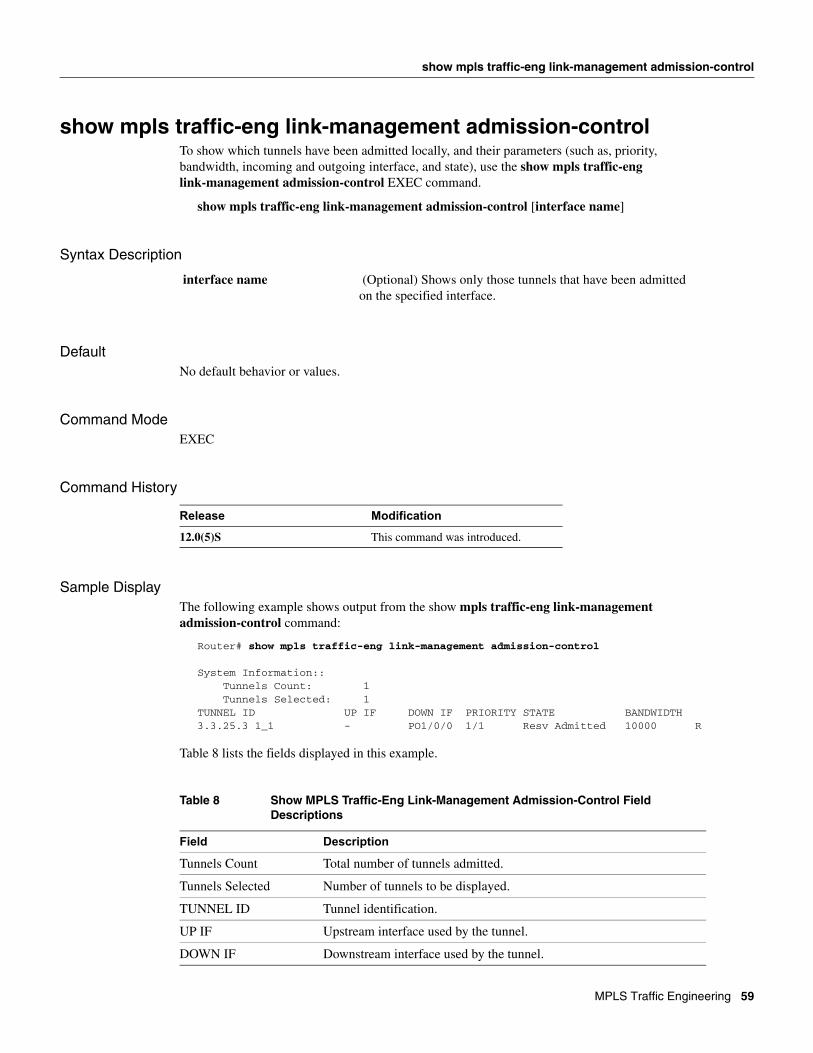
show mpls traffic-eng link-management admission-control
show mpls traffic-eng link-management admission-controlTo show which tunnels have been admitted locally, and their parameters (such as, priority, bandwidth, incoming and outgoing interface, and state), use the show mpls traffic-eng link-management admission-control EXEC command.
show mpls traffic-eng link-management admission-control [interface name]
Syntax Description
DefaultNo default behavior or values.
Command Mode EXEC
Command History
Sample DisplayThe following example shows output from the show mpls traffic-eng link-management admission-control command:
Router# show mpls traffic-eng link-management admission-control
System Information:: Tunnels Count: 1 Tunnels Selected: 1TUNNEL ID UP IF DOWN IF PRIORITY STATE BANDWIDTH 3.3.25.3 1_1 - PO1/0/0 1/1 Resv Admitted 10000 R
Table 8 lists the fields displayed in this example.
Table 8 Show MPLS Traffic-Eng Link-Management Admission-Control Field Descriptions
interface name (Optional) Shows only those tunnels that have been admitted on the specified interface.
Release Modification
12.0(5)S This command was introduced.
Field Description
Tunnels Count Total number of tunnels admitted.
Tunnels Selected Number of tunnels to be displayed.
TUNNEL ID Tunnel identification.
UP IF Upstream interface used by the tunnel.
DOWN IF Downstream interface used by the tunnel.
MPLS Traffic Engineering 59

show mpls traffic-eng link-management admission-control
Related Commands
PRIORITY Tunnel’s setup priority followed by the hold priority.
STATE Tunnel’s admission status.
BANDWIDTH Bandwidth is bits per second. If an “R” appears after the bandwidth number, it means the bandwidth has been reserved. If an “H” appears after the bandwidth number, it means the bandwidth has been temporarily held for a path message.
Command Description
show mpls traffic-eng link-management advertisements
Shows local link information currently being flooded by MPLS traffic engineering link management into the global traffic engineering topology.
show mpls traffic-eng link-management bandwidth-allocation
Shows current local link information.
show mpls traffic-eng link-management igp-neighbors Shows IGP neighbors.
show mpls traffic-eng link-management interfaces Shows per-interface resource and configuration information.
show mpls traffic-eng link-management summary Shows summary of link management information.
60 Cisco IOS Release 12.0(8)S

show mpls traffic-eng link-management advertisements
show mpls traffic-eng link-management advertisementsTo show local link information currently being flooded by MPLS traffic engineering link management into the global traffic engineering topology, use the show mpls traffic-eng link-management advertisements EXEC command.
show mpls traffic-eng link-management advertisements
Syntax DescriptionThis command has no arguments or keywords.
DefaultNo default behavior or values.
Command Mode EXEC
Command History
Sample DisplayThe following example shows output from the show mpls traffic-eng link-management advertisements command:
Router# show mpls traffic-eng link-management advertisements
Flooding Status: readyConfigured Areas: 1IGP Area[1] ID:: isis level-1 System Information:: Flooding Protocol: ISIS Header Information:: IGP System ID: 0001.0000.0001.00 MPLS TE Router ID: 10.106.0.6 Flooded Links: 1 Link ID:: 0 Link IP Address: 10.32.0.6 IGP Neighbor: ID 0001.0000.0002.00, IP 10.32.0.10 Admin. Weight: 10 Physical BW: 155520000 bits/sec Reservable BW: 5000000 bits/sec Output Bandwidth:: BW Unreserved[0]: 5000000 bits/sec BW Unreserved[1]: 1000000 bits/sec BW Unreserved[2]: 1000000 bits/sec BW Unreserved[3]: 1000000 bits/sec BW Unreserved[4]: 1000000 bits/sec BW Unreserved[5]: 1000000 bits/sec BW Unreserved[6]: 1000000 bits/sec BW Unreserved[7]: 1000000 bits/sec Affinity Bits 0x00000000
Release Modification
12.0(5)S This command was introduced.
MPLS Traffic Engineering 61

show mpls traffic-eng link-management advertisements
Table 9 lists the fields displayed in this example.
Table 9 Show MPLS Traffic-Eng Link-Management Advertisements Field Descriptions
Related Commands
Field Description
Flooding Status Enable status of the link management flooding system.
Configured Areas Number of the IGP areas configured.
IGP Area [1] ID Name of the first IGP area.
Flooding Protocol IGP being used to flood information for this area.
IGP System ID Identification used by IGP flooding this area to identify this node.
MPLS TE Router ID MPLS traffic engineering router ID.
Flooded Links Number of links flooded for this area.
Link ID Index of the link being described.
Link IP Address Local IP address of this link.
IGP Neighbor IGP neighbor on this link.
Admin. Weight Administrative weight associated with this link.
Physical BW Link’s bandwidth capacity (in bits per second).
Reservable BW Amount of reservable bandwidth on this link.
BW unreserved Amount of bandwidth that is available for reservation.
Affinity Bits Link’s attribute flags being flooded.
Command Description
show mpls traffic-eng link-management advertisements
Shows local link information currently being flooded by MPLS traffic engineering link management into the global traffic engineering topology.
show mpls traffic-eng link-management bandwidth-allocation
Shows current local link information.
show mpls traffic-eng link-management igp-neighbors
Shows IGP neighbors.
show mpls traffic-eng link-management interfaces Shows per-interface resource and configuration information.
show mpls traffic-eng link-management summary Shows summary of link management information.
62 Cisco IOS Release 12.0(8)S

show mpls traffic-eng link-management bandwidth-allocation
show mpls traffic-eng link-management bandwidth-allocationTo show current local link information, use the show mpls traffic-eng link-management bandwidth-allocation EXEC command.
show mpls traffic-eng link-management bandwidth-allocation [interface name]
Syntax Description
DefaultNo default behavior or values.
Command Mode EXEC
Command History
Usage GuidelinesAdvertised information may differ from current information depending on how flooding has been configured.
Sample DisplayThe following example shows output from this command:
Router# show mpls traffic-eng link-management bandwidth-allocation atm0/0.1
System Information:: Links Count: 3 Bandwidth Hold Time: max. 15 secondsLink ID:: AT0/0.1 (10.32.0.6) Link Status: Physical Bandwidth: 155520000 bits/sec MPLS TE Bandwidth: 5000000 bits/sec (reserved:0% in, 80% out) BW Descriptors: 1 MPLS TE Link State: MPLS TE on, RSVP on, admin-up, flooded Inbound Admission: allow-all Outbound Admission: allow-if-room Admin. Weight: 10 (IGP) IGP Neighbor Count: 1 Up Thresholds: 15 30 45 60 75 80 85 90 95 96 97 98 99 100 (default) Down Thresholds: 100 99 98 97 96 95 90 85 80 75 60 45 30 15 (default) Outbound Bandwidth Information (bits/second): KEEP PRIORITY BW HELD BW TOTAL HELD BW LOCKED BW TOTAL LOCKED 0 0 0 0 0 1 0 0 4000000 4000000
interface name (Optional) Shows only those tunnels that have been admitted on the specified interface.
Release Modification
12.0(5)S This command was introduced.
MPLS Traffic Engineering 63

show mpls traffic-eng link-management bandwidth-allocation
2 0 0 0 4000000 3 0 0 0 4000000 4 0 0 0 4000000 5 0 0 0 4000000 6 0 0 0 4000000 7 0 0 0 4000000
Table 10 lists the fields displayed in this example.
Table 10 Show MPLS Traffic-Eng Link-Management Bandwidth-Allocation Field Descriptions
Related Commands
Field Description
Links Count Number of links configured for MPLS traffic engineering.
Bandwidth Holdtime
Link ID Interface name and IP address of the link being described.
Physical Bandwidth Link’s bandwidth capacity (in bits per second).
MPLS TE Bandwidth Amount of reservable bandwidth on this link.
BW Descriptors Number of bandwidth allocations on this link.
MPLS TE Link State Status of the link’s MPLS traffic engineering-related functions.
Inbound Admission Link’s admission policy for incoming tunnels.
Outbound Admission Link’s admission policy for outgoing tunnels.
Admin. Weight Administrative weight associated with this link.
Up Thresholds Link’s bandwidth thresholds for allocations.
Down Thresholds Link’s bandwidth thresholds for deallocations.
IGP Neighbor List of the IGP neighbors directly reachable over this link.
KEEP PRIORITY Priority levels for the link’s bandwidth allocations.
BW HELD Amount of bandwidth (in bits per seconds) temporarily held at this priority for path messages.
BW TOTAL HELD Bandwidth held at this priority and those above it.
BW LOCKED Amount of bandwidth reserved at this priority.
BW TOTAL LOCKED Bandwidth reserved at this priority and those above.
Command Description
show mpls traffic-eng link-management advertisements
Shows local link information currently being flooded by MPLS traffic engineering link management into the global traffic engineering topology.
show mpls traffic-eng link-management bandwidth-allocation
Shows current local link information.
show mpls traffic-eng link-management igp-neighbors Shows IGP neighbors.
64 Cisco IOS Release 12.0(8)S

show mpls traffic-eng link-management bandwidth-allocation
show mpls traffic-eng link-management interfaces Shows per-interface resource and configuration information.
show mpls traffic-eng link-management summary Shows summary of link management information.
MPLS Traffic Engineering 65
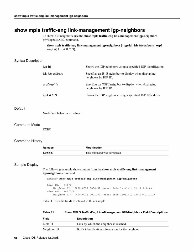
show mpls traffic-eng link-management igp-neighbors
show mpls traffic-eng link-management igp-neighborsTo show IGP neighbors, use the show mpls traffic-eng link-management igp-neighbors privileged EXEC command.
show mpls traffic-eng link-management igp-neighbors [{igp-id {isis isis-address | ospf ospf-id} | ip A.B.C.D}]
Syntax Description
DefaultNo default behavior or values.
Command Mode EXEC
Command History
Sample DisplayThe following example shows output from the show mpls traffic-eng link-management igp-neighbors command
Router# show mpls traffic-eng line-management igp-neighbors
Link ID:: Et0/2 Neighbor ID: 0000.0024.0004.02 (area: isis level-1, IP: 0.0.0.0)Link ID:: PO1/0/0 Neighbor ID: 0000.0026.0001.00 (area: isis level-1, IP: 170.1.1.2)
Table 11 lists the fields displayed in this example.
Table 11 Show MPLS Traffic-Eng Link-Management IGP-Neighbors Field Descriptions
igp-id Shows the IGP neighbors using a specified IGP identification.
isis isis-address Specifies an IS-IS neighbor to display when displaying neighbors by IGP ID.
ospf ospf-id Specifies an OSPF neighbor to display when displaying neighbors by IGP ID.
ip A.B.C.D. Shows the IGP neighbors using a specified IGP IP address.
Release Modification
12.0(5)S This command was introduced.
Field Description
Link ID Link by which the neighbor is reached.
Neighbor ID IGP’s identification information for the neighbor.
66 Cisco IOS Release 12.0(8)S

show mpls traffic-eng link-management igp-neighbors
Related Commands
Command Description
show mpls traffic-eng link-management advertisements Shows local link information currently being flooded by MPLS traffic engineering link management into the global traffic engineering topology.
show mpls traffic-eng link-management bandwidth-allocation Shows current local link information.
show mpls traffic-eng link-management igp-neighbors Shows IGP neighbors.
show mpls traffic-eng link-management interfaces Shows per-interface resource and configuration information.
show mpls traffic-eng link-management summary Shows summary of link management information.
MPLS Traffic Engineering 67

show mpls traffic-eng link-management interfaces
show mpls traffic-eng link-management interfacesTo show per-interface resource and configuration information, use the show mpls traffic-eng link-management interfaces EXEC command.
show mpls traffic-eng link-management interfaces [interface]
Syntax Description
DefaultNo default behavior or values.
Command Mode EXEC
Command History
Sample DisplayRouter# show mpls traffic-eng link-management interfacesSystem Information::Links Count: 3Link ID:: Et1/1/1 (10.1.0.6) Link Status: Physical Bandwidth: 10000000 bits/sec MPLS TE Bandwidth: 5000000 bits/sec (reserved:0% in, 0% out) MPLS TE Link State: MPLS TE on, RSVP on Inbound Admission: reject-huge Outbound Admission: allow-if-room Admin. Weight: 10 (IGP) IGP Neighbor Count: 2 IGP Neighbor: ID 0000.0000.0000.02, IP 0.0.0.0 (Up) IGP Neighbor: ID 0001.0000.0001.02, IP 0.0.0.0 (Down) Flooding Status for each configured area [1]: IGP Area[1 isis level-1: not flooded (Reason:Interface has been administratively disabled)Link ID:: AT0/0.1 (10.32.0.6) Link Status: Physical Bandwidth: 155520000 bits/sec MPLS TE Bandwidth: 5000000 bits/sec (reserved:0% in, 80% out) MPLS TE Link State: MPLS TE on, RSVP on, admin-up, flooded Inbound Admission: allow-all Outbound Admission: allow-if-room Admin. Weight: 10 (IGP) IGP Neighbor Count: 1 IGP Neighbor: ID 0001.0000.0002.00, IP 10.32.0.10 (Up) Flooding Status for each configured area [1]: IGP Area[1 isis level-1: flooded
interface (Optional) Specifies the name of a single interface for which information is to be displayed.
Release Modification
12.0(5)S This command was introduced.
68 Cisco IOS Release 12.0(8)S
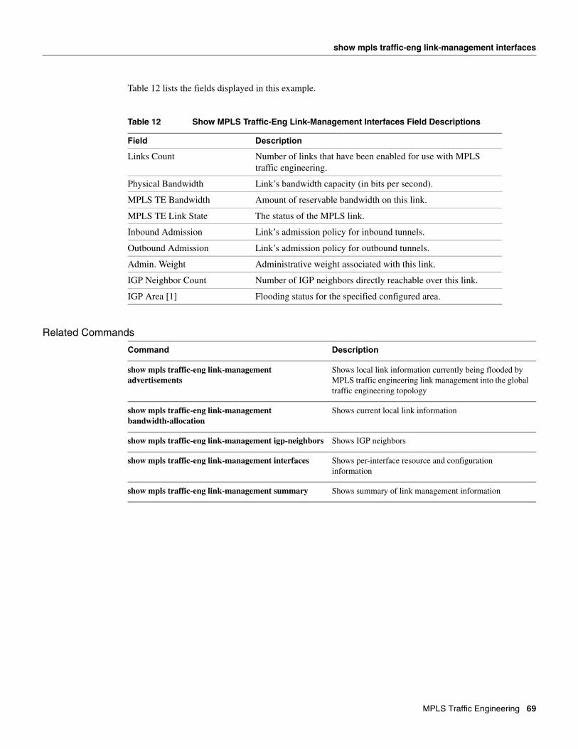
show mpls traffic-eng link-management interfaces
Table 12 lists the fields displayed in this example.
Table 12 Show MPLS Traffic-Eng Link-Management Interfaces Field Descriptions
Related Commands
Field Description
Links Count Number of links that have been enabled for use with MPLS traffic engineering.
Physical Bandwidth Link’s bandwidth capacity (in bits per second).
MPLS TE Bandwidth Amount of reservable bandwidth on this link.
MPLS TE Link State The status of the MPLS link.
Inbound Admission Link’s admission policy for inbound tunnels.
Outbound Admission Link’s admission policy for outbound tunnels.
Admin. Weight Administrative weight associated with this link.
IGP Neighbor Count Number of IGP neighbors directly reachable over this link.
IGP Area [1] Flooding status for the specified configured area.
Command Description
show mpls traffic-eng link-management advertisements
Shows local link information currently being flooded by MPLS traffic engineering link management into the global traffic engineering topology
show mpls traffic-eng link-management bandwidth-allocation
Shows current local link information
show mpls traffic-eng link-management igp-neighbors Shows IGP neighbors
show mpls traffic-eng link-management interfaces Shows per-interface resource and configuration information
show mpls traffic-eng link-management summary Shows summary of link management information
MPLS Traffic Engineering 69
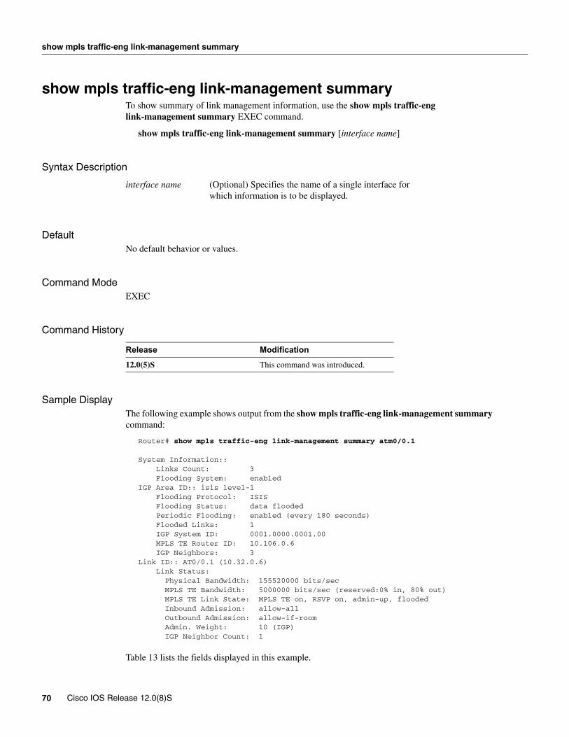
show mpls traffic-eng link-management summary
show mpls traffic-eng link-management summaryTo show summary of link management information, use the show mpls traffic-eng link-management summary EXEC command.
show mpls traffic-eng link-management summary [interface name]
Syntax Description
DefaultNo default behavior or values.
Command Mode EXEC
Command History
Sample DisplayThe following example shows output from the show mpls traffic-eng link-management summary command:
Router# show mpls traffic-eng link-management summary atm0/0.1
System Information:: Links Count: 3 Flooding System: enabledIGP Area ID:: isis level-1 Flooding Protocol: ISIS Flooding Status: data flooded Periodic Flooding: enabled (every 180 seconds) Flooded Links: 1 IGP System ID: 0001.0000.0001.00 MPLS TE Router ID: 10.106.0.6 IGP Neighbors: 3Link ID:: AT0/0.1 (10.32.0.6) Link Status: Physical Bandwidth: 155520000 bits/sec MPLS TE Bandwidth: 5000000 bits/sec (reserved:0% in, 80% out) MPLS TE Link State: MPLS TE on, RSVP on, admin-up, flooded Inbound Admission: allow-all Outbound Admission: allow-if-room Admin. Weight: 10 (IGP) IGP Neighbor Count: 1
Table 13 lists the fields displayed in this example.
interface name (Optional) Specifies the name of a single interface for which information is to be displayed.
Release Modification
12.0(5)S This command was introduced.
70 Cisco IOS Release 12.0(8)S
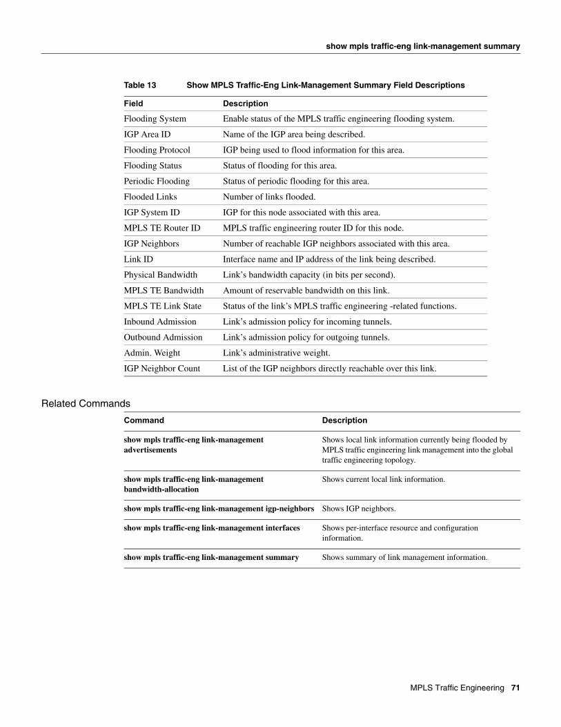
show mpls traffic-eng link-management summary
Table 13 Show MPLS Traffic-Eng Link-Management Summary Field Descriptions
Related Commands
Field Description
Flooding System Enable status of the MPLS traffic engineering flooding system.
IGP Area ID Name of the IGP area being described.
Flooding Protocol IGP being used to flood information for this area.
Flooding Status Status of flooding for this area.
Periodic Flooding Status of periodic flooding for this area.
Flooded Links Number of links flooded.
IGP System ID IGP for this node associated with this area.
MPLS TE Router ID MPLS traffic engineering router ID for this node.
IGP Neighbors Number of reachable IGP neighbors associated with this area.
Link ID Interface name and IP address of the link being described.
Physical Bandwidth Link’s bandwidth capacity (in bits per second).
MPLS TE Bandwidth Amount of reservable bandwidth on this link.
MPLS TE Link State Status of the link’s MPLS traffic engineering -related functions.
Inbound Admission Link’s admission policy for incoming tunnels.
Outbound Admission Link’s admission policy for outgoing tunnels.
Admin. Weight Link’s administrative weight.
IGP Neighbor Count List of the IGP neighbors directly reachable over this link.
Command Description
show mpls traffic-eng link-management advertisements
Shows local link information currently being flooded by MPLS traffic engineering link management into the global traffic engineering topology.
show mpls traffic-eng link-management bandwidth-allocation
Shows current local link information.
show mpls traffic-eng link-management igp-neighbors Shows IGP neighbors.
show mpls traffic-eng link-management interfaces Shows per-interface resource and configuration information.
show mpls traffic-eng link-management summary Shows summary of link management information.
MPLS Traffic Engineering 71

show mpls traffic-eng topology
show mpls traffic-eng topology To show the MPLS traffic engineering global topology as currently known at this node, use the show mpls traffic-eng topology privileged EXEC command.
show mpls traffic-eng topology [{A.B.C.D | igp-id {isis nsapaddr | ospf A.B.C.D}] [brief]
Syntax Description
DefaultNo default behavior or values.
Command Mode EXEC
Command History
Sample DisplayThe following example shows output from the show mpls traffic-eng topology command:
Router# show mpls traffic-eng topology
My_System_id: 0000.0025.0003.00 IGP Id: 0000.0024.0004.00, MPLS TE Id:24.4.4.4 Router Node link[0 ]:Intf Address: 150.1.1.4 Nbr IGP Id: 0000.0024.0004.02, admin_weight:10, affinity_bits:0x0 max_link_bw:10000 max_link_reservable: 10000 allocated reservable allocated reservable --------- ---------- --------- ---------- bw[0]: 0 10000 bw[1]: 0 10000 bw[2]: 0 10000 bw[3]: 0 10000 bw[4]: 0 10000 bw[5]: 0 10000 bw[6]: 0 10000 bw[7]: 0 10000
A.B.C.D Specifies the node by the IP address (router identifier to interface address).
igp-id Specifies the node by IGP router identifier.
isis nsapaddr Specifies the node by router identification (nsapaddr) if using IS-IS.
ospf A.B.C.D Specifies the node by router identifier if using OSPF.
brief (Optional) The brief form of the output gives a less detailed version of the topology.
Release Modification
12.0(5)S This command was introduced.
72 Cisco IOS Release 12.0(8)S
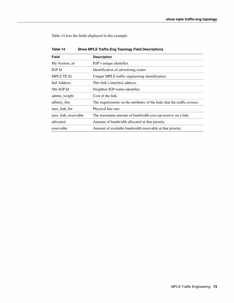
show mpls traffic-eng topology
Table 14 lists the fields displayed in this example.
Table 14 Show MPLS Traffic-Eng Topology Field Descriptions
Field Description
My-System_id IGP’s unique identifier.
IGP Id Identification of advertising router.
MPLS TE Id Unique MPLS traffic engineering identification.
Intf Address This link’s interface address.
Nbr IGP Id Neighbor IGP router identifier.
admin_weight Cost of the link.
affinity_bits The requirements on the attributes of the links that the traffic crosses.
max_link_bw Physical line rate.
max_link_reservable The maximum amount of bandwidth you can reserve on a link.
allocated Amount of bandwidth allocated at that priority.
reservable Amount of available bandwidth reservable at that priority.
MPLS Traffic Engineering 73
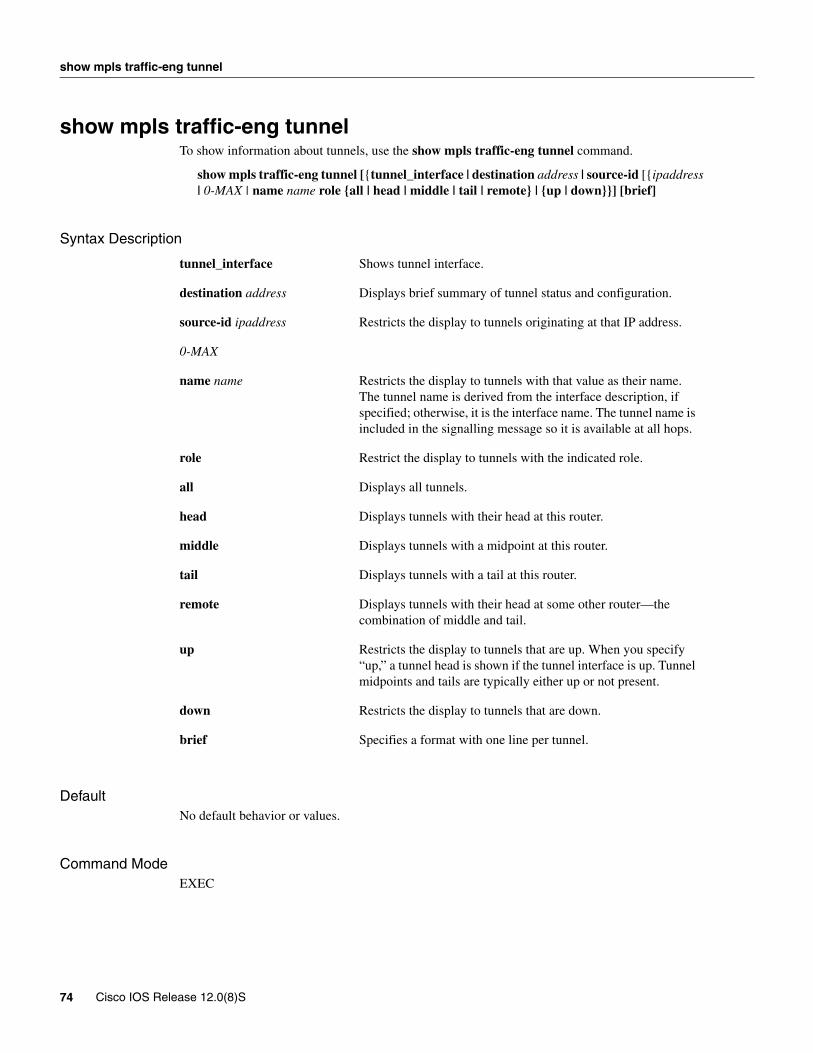
show mpls traffic-eng tunnel
show mpls traffic-eng tunnelTo show information about tunnels, use the show mpls traffic-eng tunnel command.
show mpls traffic-eng tunnel [{tunnel_interface | destination address | source-id [{ipaddress | 0-MAX | name name role {all | head | middle | tail | remote} | {up | down}}] [brief]
Syntax Description
DefaultNo default behavior or values.
Command ModeEXEC
tunnel_interface Shows tunnel interface.
destination address Displays brief summary of tunnel status and configuration.
source-id ipaddress Restricts the display to tunnels originating at that IP address.
0-MAX
name name Restricts the display to tunnels with that value as their name. The tunnel name is derived from the interface description, if specified; otherwise, it is the interface name. The tunnel name is included in the signalling message so it is available at all hops.
role Restrict the display to tunnels with the indicated role.
all Displays all tunnels.
head Displays tunnels with their head at this router.
middle Displays tunnels with a midpoint at this router.
tail Displays tunnels with a tail at this router.
remote Displays tunnels with their head at some other router—the combination of middle and tail.
up Restricts the display to tunnels that are up. When you specify “up,” a tunnel head is shown if the tunnel interface is up. Tunnel midpoints and tails are typically either up or not present.
down Restricts the display to tunnels that are down.
brief Specifies a format with one line per tunnel.
74 Cisco IOS Release 12.0(8)S
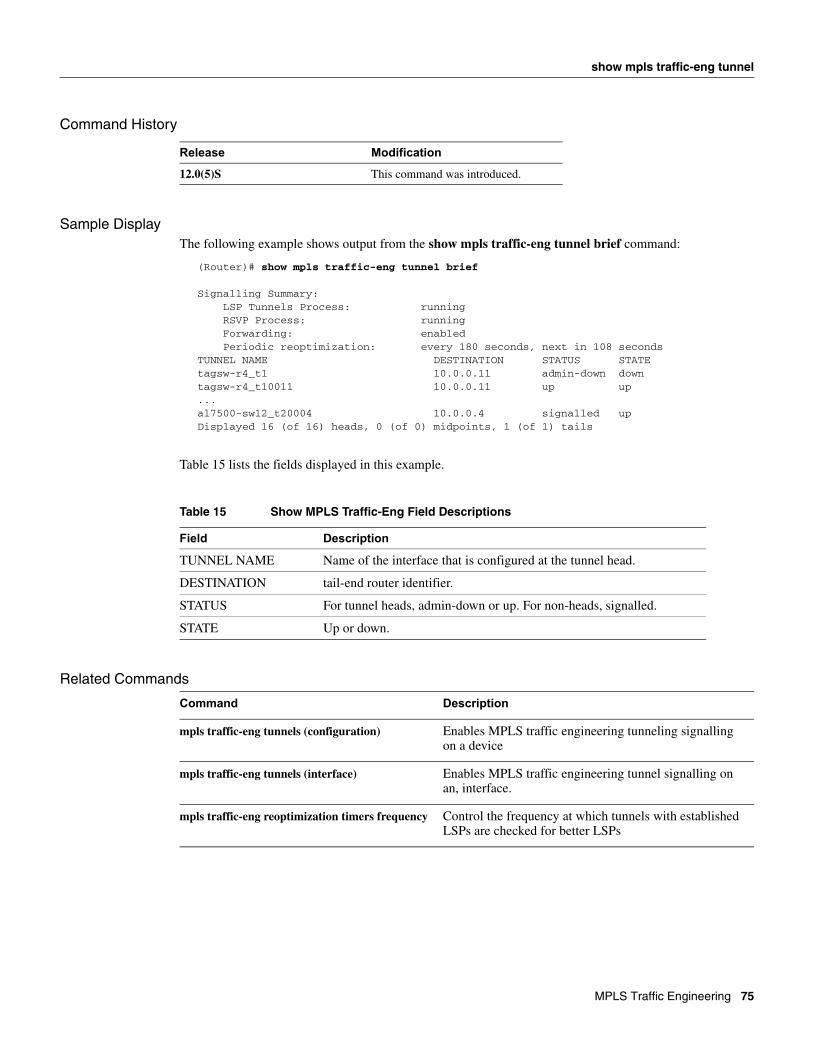
show mpls traffic-eng tunnel
Command History
Sample DisplayThe following example shows output from the show mpls traffic-eng tunnel brief command:
(Router)# show mpls traffic-eng tunnel brief
Signalling Summary: LSP Tunnels Process: running RSVP Process: running Forwarding: enabled Periodic reoptimization: every 180 seconds, next in 108 secondsTUNNEL NAME DESTINATION STATUS STATEtagsw-r4_t1 10.0.0.11 admin-down downtagsw-r4_t10011 10.0.0.11 up up...al7500-sw12_t20004 10.0.0.4 signalled upDisplayed 16 (of 16) heads, 0 (of 0) midpoints, 1 (of 1) tails
Table 15 lists the fields displayed in this example.
Table 15 Show MPLS Traffic-Eng Field Descriptions
Related Commands
Release Modification
12.0(5)S This command was introduced.
Field Description
TUNNEL NAME Name of the interface that is configured at the tunnel head.
DESTINATION tail-end router identifier.
STATUS For tunnel heads, admin-down or up. For non-heads, signalled.
STATE Up or down.
Command Description
mpls traffic-eng tunnels (configuration) Enables MPLS traffic engineering tunneling signalling on a device
mpls traffic-eng tunnels (interface) Enables MPLS traffic engineering tunnel signalling on an, interface.
mpls traffic-eng reoptimization timers frequency Control the frequency at which tunnels with established LSPs are checked for better LSPs
MPLS Traffic Engineering 75
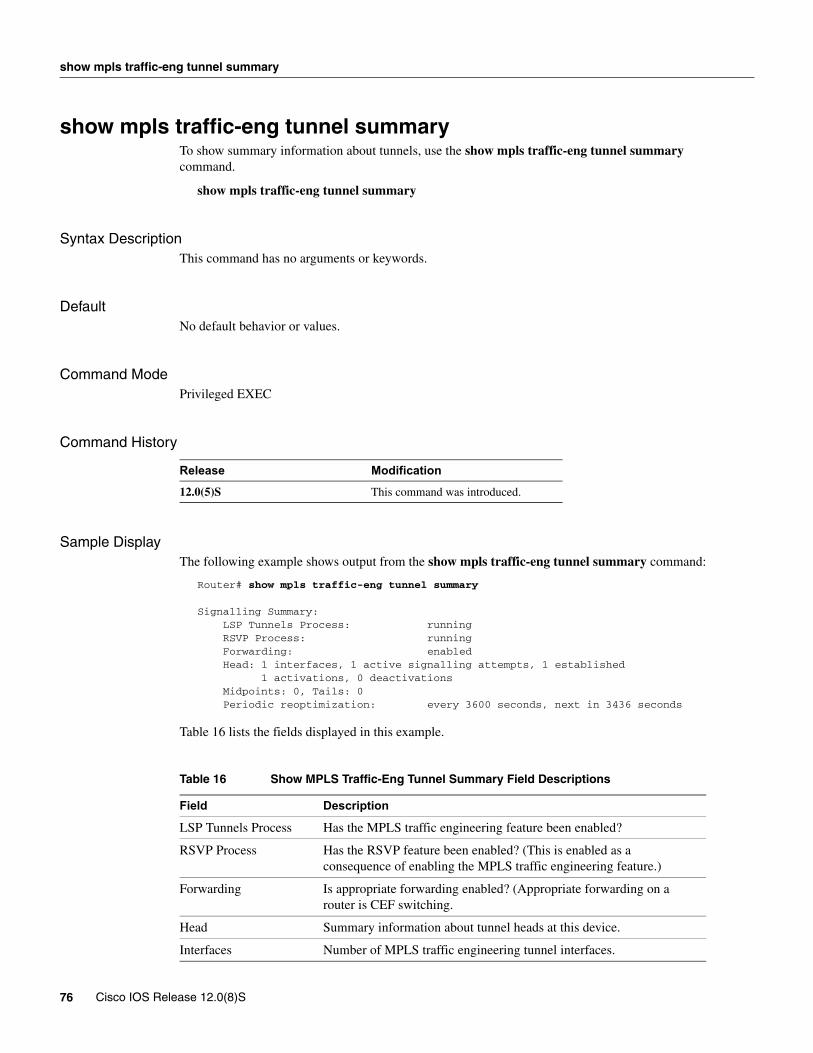
show mpls traffic-eng tunnel summary
show mpls traffic-eng tunnel summaryTo show summary information about tunnels, use the show mpls traffic-eng tunnel summary command.
show mpls traffic-eng tunnel summary
Syntax DescriptionThis command has no arguments or keywords.
DefaultNo default behavior or values.
Command Mode Privileged EXEC
Command History
Sample DisplayThe following example shows output from the show mpls traffic-eng tunnel summary command:
Router# show mpls traffic-eng tunnel summary
Signalling Summary: LSP Tunnels Process: running RSVP Process: running Forwarding: enabled Head: 1 interfaces, 1 active signalling attempts, 1 established 1 activations, 0 deactivations Midpoints: 0, Tails: 0 Periodic reoptimization: every 3600 seconds, next in 3436 seconds
Table 16 lists the fields displayed in this example.
Table 16 Show MPLS Traffic-Eng Tunnel Summary Field Descriptions
Release Modification
12.0(5)S This command was introduced.
Field Description
LSP Tunnels Process Has the MPLS traffic engineering feature been enabled?
RSVP Process Has the RSVP feature been enabled? (This is enabled as a consequence of enabling the MPLS traffic engineering feature.)
Forwarding Is appropriate forwarding enabled? (Appropriate forwarding on a router is CEF switching.
Head Summary information about tunnel heads at this device.
Interfaces Number of MPLS traffic engineering tunnel interfaces.
76 Cisco IOS Release 12.0(8)S
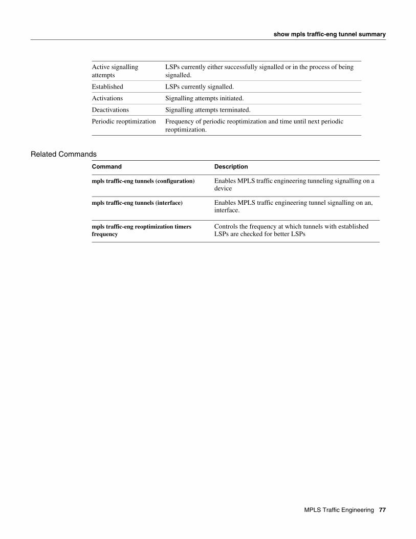
show mpls traffic-eng tunnel summary
Related Commands
Active signalling attempts
LSPs currently either successfully signalled or in the process of being signalled.
Established LSPs currently signalled.
Activations Signalling attempts initiated.
Deactivations Signalling attempts terminated.
Periodic reoptimization Frequency of periodic reoptimization and time until next periodic reoptimization.
Command Description
mpls traffic-eng tunnels (configuration) Enables MPLS traffic engineering tunneling signalling on a device
mpls traffic-eng tunnels (interface) Enables MPLS traffic engineering tunnel signalling on an, interface.
mpls traffic-eng reoptimization timers frequency
Controls the frequency at which tunnels with established LSPs are checked for better LSPs
MPLS Traffic Engineering 77
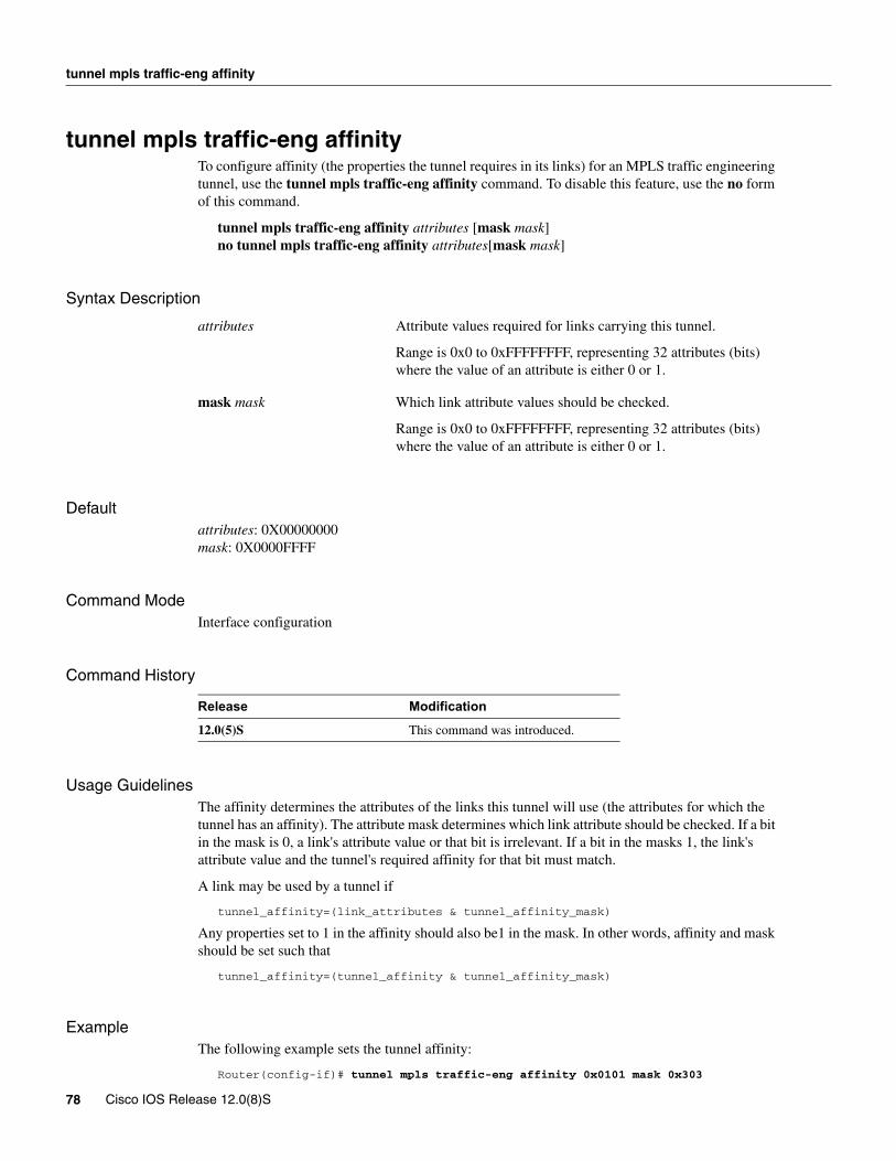
tunnel mpls traffic-eng affinity
tunnel mpls traffic-eng affinityTo configure affinity (the properties the tunnel requires in its links) for an MPLS traffic engineering tunnel, use the tunnel mpls traffic-eng affinity command. To disable this feature, use the no form of this command.
tunnel mpls traffic-eng affinity attributes [mask mask]no tunnel mpls traffic-eng affinity attributes[mask mask]
Syntax Description
Defaultattributes: 0X00000000mask: 0X0000FFFF
Command Mode Interface configuration
Command History
Usage GuidelinesThe affinity determines the attributes of the links this tunnel will use (the attributes for which the tunnel has an affinity). The attribute mask determines which link attribute should be checked. If a bit in the mask is 0, a link's attribute value or that bit is irrelevant. If a bit in the masks 1, the link's attribute value and the tunnel's required affinity for that bit must match.
A link may be used by a tunnel if
tunnel_affinity=(link_attributes & tunnel_affinity_mask)
Any properties set to 1 in the affinity should also be1 in the mask. In other words, affinity and mask should be set such that
tunnel_affinity=(tunnel_affinity & tunnel_affinity_mask)
ExampleThe following example sets the tunnel affinity:
Router(config-if)# tunnel mpls traffic-eng affinity 0x0101 mask 0x303
attributes Attribute values required for links carrying this tunnel.
Range is 0x0 to 0xFFFFFFFF, representing 32 attributes (bits) where the value of an attribute is either 0 or 1.
mask mask Which link attribute values should be checked.
Range is 0x0 to 0xFFFFFFFF, representing 32 attributes (bits) where the value of an attribute is either 0 or 1.
Release Modification
12.0(5)S This command was introduced.
78 Cisco IOS Release 12.0(8)S

tunnel mpls traffic-eng affinity
Related Commands
Command Description
mpls traffic-eng attribute-flags Sets the attributes for the interface.
tunnel mode mpls traffic-eng Sets the mode of a tunnel to MPLS for traffic engineering.
MPLS Traffic Engineering 79
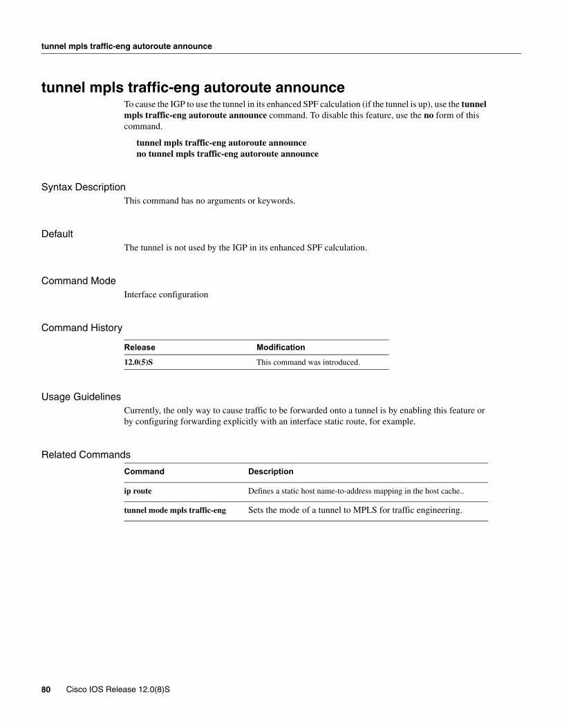
tunnel mpls traffic-eng autoroute announce
tunnel mpls traffic-eng autoroute announceTo cause the IGP to use the tunnel in its enhanced SPF calculation (if the tunnel is up), use the tunnel mpls traffic-eng autoroute announce command. To disable this feature, use the no form of this command.
tunnel mpls traffic-eng autoroute announceno tunnel mpls traffic-eng autoroute announce
Syntax DescriptionThis command has no arguments or keywords.
DefaultThe tunnel is not used by the IGP in its enhanced SPF calculation.
Command Mode Interface configuration
Command History
Usage GuidelinesCurrently, the only way to cause traffic to be forwarded onto a tunnel is by enabling this feature or by configuring forwarding explicitly with an interface static route, for example.
Related Commands
Release Modification
12.0(5)S This command was introduced.
Command Description
ip route Defines a static host name-to-address mapping in the host cache..
tunnel mode mpls traffic-eng Sets the mode of a tunnel to MPLS for traffic engineering.
80 Cisco IOS Release 12.0(8)S
tunnel mpls traffic-eng autoroute metric
tunnel mpls traffic-eng autoroute metricTo specify the MPLS traffic-engineering tunnel metric used by IGP enhanced SPF calculation, use the tunnel mpls traffic-eng autoroute metric command. To disable this feature, use the no form of this command.
tunnel mpls traffic-eng autoroute metric {absolute|relative} valueno tunnel mpls traffic-eng autoroute metric
Syntax Description
DefaultThe default is metric relative 0.
Command Mode Interface configuration
Command History
Usage Guidelines
Example
Related Commands
metric The MPLS traffic engineering tunnel metric
absolute The MPLS traffic-engineering tunnel metric mode absolute: a positive metric value can be supplied
relative The MPLS traffic-engineering tunnel metric mode relative: a positive, negative or zero value can be supplied
Release Modification
12.0(5)S This command was introduced.
Command Description
show mpls traffic-eng autoroute Shows tunnels announced to IGP, including interface, destination, and bandwidth.
tunnel mpls traffic-eng autoroute Instructs the IGP to use the tunnel in its enhanced SPF calculation (if the tunnel is up).
MPLS Traffic Engineering 81

tunnel mpls traffic-eng bandwidth
tunnel mpls traffic-eng bandwidthTo configure bandwidth required for an MPLS traffic engineering tunnel, use the tunnel mpls traffic-eng bandwidth command. To disable this feature, use the no form of this command.
tunnel mpls traffic-eng bandwidth bandwidth no tunnel mpls traffic-eng bandwidth bandwidth
Syntax Description
DefaultDefault bandwidth required is 0.
Command ModeConfiguration interface
Command History
Usage Guidelines
Related Commands
bandwidth The bandwidth required for an MPLS traffic engineering tunnel. Bandwidth is specified in kilobits per seconds.
Release Modification
12.0(5)S This command was introduced.
Command Description
show mpls traffic-eng tunnel Displays tunnel information.
82 Cisco IOS Release 12.0(8)S
tunnel mpls traffic-eng path-option
tunnel mpls traffic-eng path-optionTo configure a path option for an MPLS traffic engineering tunnel, use the tunnel mpls traffic-eng path-option command. To disable this feature, use the no form of this command.
tunnel mpls traffic-eng path-option identifier path-number name path-nameno tunnel mpls traffic-eng path-option identifier path-number name path-name
Syntax Description
DefaultNo default behavior or values.
Command Mode Interface configuration
Command History
Usage GuidelinesMultiple path setup options may be configured for a single tunnel. For example, you can configure several explicit paths and a dynamic option for one tunnel. Path setup prefers options with lower numbers to options with higher numbers, so option 1 is the most preferred option.
Related Commands
identifier path-number Uses the IP explicit path with the indicated path number.
name path-name Uses the IP explicit path with the indicated path name.
Release Modification
12.0(5)S This command was introduced.
Command Description
ip explicit-path Enter the subcommand mode for IP explicit paths to create or modify the named path.
show ip explicit-paths Shows configured IP explict paths.
tunnel mode mpls traffic-eng priority Configures setup and reservation priority for a tunnel.
MPLS Traffic Engineering 83
tunnel mpls traffic-eng priority
tunnel mpls traffic-eng priorityTo configure setup and reservation priority for an MPLS traffic engineering tunnel, use the tunnel mpls traffic-eng priority command. To disable this feature, use the no form of this command.
tunnel mpls traffic-eng priority setup-priority [hold-priority] no tunnel traffic-eng priority setup-priority [hold-priority]
Syntax Description
Defaultsetup-priority: 7hold-priority: setup priority
Command Mode Interface configuration
Command History
Usage GuidelinesThe priority mechanism allows a hard-to-fit LSP to preempt easy-to-fit LSPs so that the easy-to fit LSPs can be re-established once the hard-to-fit LSP has been placed.
Typically, setup and hold priorities are equal. However, a separate hold priority allows a subset on tunnels to not preempt on setup, but to not be preempted once established.
Setup priority may not be better than (numerically smaller than) hold priority.
setup-priority The priority used when signalling an LSP for this tunnel to figure out what existing tunnels are eligible to be preempted. The range is 0 to 7, where a lower numeric value indicates a higher priority. Therefore, an LSP with a setup priority of 0 can preempt any LSP with a non-0 priority.
hold-priority The priority associated with an LSP for this tunnel once established to figure out if it should be preempted by other LSPs that are being signalled. The range is 0 to 7, where a lower numeric value indicates a higher priority.
Release Modification
12.0(5)S This command was introduced.
84 Cisco IOS Release 12.0(8)S

tunnel mpls traffic-eng priority
Related Commands
Command Description
tunnel mode mpls traffic-eng Sets the mode of a tunnel to MPLS for traffic engineering.
MPLS Traffic Engineering 85

tunnel mode mpls traffic-eng
tunnel mode mpls traffic-engTo set the mode of a tunnel to MPLS for traffic engineering, use the tunnel mode mpls traffic-eng command. To disable this feature, use the no form of this command.
tunnel mode mpls traffic-eng [gre-ip]no tunnel mode mpls traffic-eng [gre-ip]
Syntax Description
DefaultNo default behavior or values.
Command Mode Interface configuration
Command History
Usage GuidelinesThis command specifies that the tunnel interface is for an MPLS traffic engineering tunnel, and enables the various tunnel MPLS configuration options.
Related Commands
gre-ip (Optional)
Release Modification
12.0(5)S This command was introduced.
Command Description
tunnel mpls traffic-eng affinity Configures tunnel affinity (the properties the tunnel requires in its links).
tunnel mpls traffic-eng autoroute announce Instructs the IGP to use the tunnel in its enhanced SPF calculation (if the tunnel is up).
tunnel mpls traffic-eng bandwidth Configures bandwidth required for an MPLS traffic engineering tunnel.
tunnel mpls traffic-eng path-option Configures a path option.
tunnel mpls traffic-eng priority Configures setup and reservation priority for a tunnel.
86 Cisco IOS Release 12.0(8)S

tunnel mode mpls traffic-eng
Glossaryaffinity bits—an MPLS traffic engineering tunnel's requirements on the attributes of the links it will cross. The tunnel's affinity bits and affinity mask must match up with the attributes of the various links carrying the tunnel.
call admission precedence—an MPLS traffic engineering tunnel with a higher priority will, if necessary, preempt an MPLS traffic engineering tunnel with a lower priority. An expected use is that tunnels that are harder to route will have a higher priority, and can preempt tunnels that are easier to route, on the assumption that those lower priority tunnels can find another path.
constraint-based routing—Procedures and protocols used to determine a route across a backbone taking into account resource requirements and resource availability, instead of simply using the shortest path.
flow—A traffic load entering the backbone at one point—point of presence (POP)—and leaving it from another, that must be traffic engineered across the backbone. The traffic load will be carried across one or more LSP tunnels running from the entry POP to the exit POP.
head-end—The upstream, transmit end of a tunnel.
IGP—Interior Gateway Protocol. Internet protocol used to exchange routing information within an autonomous system. Examples of common IGPs include IGRP, OSPF, and RIP.
IS-IS—Intermediate System-to-Intermediate System. OSI link-state hierarchal routing protocol whereby Intermediate System (IS) routers exchange routing information based on a single metric to determine network topology.
label-switched path (LSP) tunnel—A configured connection between two routers, using label switching to carry the packets. label-switched path (LSP)—A sequence of hops (R0...Rn) in which a packet travels from R0 to Rn through label switching mechanisms. A -switched path can be chosen dynamically, based on normal routing mechanisms, or through configuration.
Label Switching Router (LSR)—A Layer 3 router that forwards packets based on the value of a label encapsulated in the packets.
LCAC—Link-level (per hop) call admission control.
LSA—Link-state advertisement. Flooded packet used by OSPF that contains information about neighbors and path costs. In IS-IS, LSAs are used by the receiving routers to maintain their routing tables.
Multiprotocol Label Switching traffic engineering—MPLS traffic engineering. A constraint-based routing algorithm for routing TSP tunnels.
OSPF—Open shortest path first (OSPF). A link state routing protocol used for routing IP.
RSVP—Resource Reservation Protocol. Protocol for reserving network resources to provide Quality of Service guarantees to application flows.
tail-end—The downstream, receive end of a tunnel.
traffic engineering—The techniques and processes used to cause routed traffic to travel through the network on a path other than the one that would have been chosen if standard routing methods had been used.
MPLS Traffic Engineering 87

Glossary
88 Cisco IOS Release 12.0(8)S


