
MRQ SeriesSize oflinear
motion parts
32
40
Output ofrotary motion parts
(at 0.5 MPa)
1.02 N·m
1.91 N·m
Rotatingangle
80 to 100°170 to 190° 80 to 100°170 to 190°
Linear motion stroke (mm)
A rectilinear rotation unit that compactly integratesa slim cylinder and a rotary actuator.
Application Example
Connecting ports are provided “IN” two positions as standard specifications.
MRQ Series
Rotary Cylinder
Size: 32, 40
343
The timing of the rectilinear and rota-tional movements can be set as desired.Rotational movements are possible at the forward end, the back end, or during a rectilinear movement.
Effective output(At 0.5 MPa)Size 32 = 1 N·mSize 40 = 1.9 N·m
Rotating angle: 80 to 100°170 to 190°
Backlash: Within 2°
Smooth rotary movementRoller bearings are used in the rotating portion.
Equipped with an auto switch(Mountable on both sides)Magnet included as standard.
Reed auto switch: D-A7/A8Solid state auto switch: D-F7/J7( )
An air cushion is also available.
Angle adjustableThe rotation angle can be adjusted 5° at each end, or 10° at both ends.
Releasinga workpiece
Changing direction
5 10 15 20 25 30 40 50 75 100
A connecting port can be selected from two positions that are available on the rotation unit. Connecting
portM5 x 0.8
Connectingport
CRB2
CRB1
MSU
CRJ
CRA1
CRQ2
MSQ
MSZCRQ2XMSQX
MRQ
D-
MRQ

Moment of Inertia and Rotation Time
Size
3240
Allowable kinetic energy(J)
0.023
0.028
Adjustable rotation time range thatensures stable operation (s/90°)
0.2 to 1
0.2 to 1
00.1 0.2 0.3 0.4 0.5 0.6 0.7 0.8 0.9 1.0
0.001
0.0020.0025
0.003
0.004
0.005
0.00632
Sel
ectin
g ra
nge
40 S
elec
ting
rang
e
Rotation time (s/90°)
Mom
ent o
f ine
rtia
(kg
·m2 )
How to Calculate the Load Energy
Allowable Kinetic Energy
E = · · 2, =
= 0.2 x = 0.004 kg·m22
0.22
If the product is used in a state in which its kinetic energy exceeds the allowable value, it could cause damage inside the product, which could cause the product to go out of the order. The bounce phenomenon may also occur at the rotating ends; thus, make sure that the kinetic energy does not exceed the allowable value during design and operation.(A chart that depicts the moments of inertia and the rotation time is provided to facilitate the selection process.)
1. Setting of rotation timeSet the rotation time within the adjustable rotation time range that ensures stable operation, based on the table on the right.Setting the speed higher than the upper limit could cause the actuator to stick or slip.
Formula of moment of inertia is subject to load shape. Refer to the moment of inertia formula on pages 24 to 29.
2. Calculating of the moment of inertia
3. Selecting of a modelSelect models by applying the moment of inertia and rotation time which have been found to the charts below.
<How to read the graph>• Moment of inertia········0.0025 kg·m2 • Rotation time········0.7 s/90°, size 40 will be selected.
<Calculation example>Load shape: Column with a radius of 0.2 m and a weight of 0.2 kg Rotation time: 0.9 s/90°
In the chart that depicts the moment of inertia and the rotation time, find the intersecting point of the lines that extend from the locations corresponding to 0.004 kg·m2 on the vertical axis (moment of inertia) and to 0.9 s/90° on the horizontal axis (rotation time). Select size 40 because the intersecting point is found within the selection range for size 40.
E : Kinetic energy············(J)
I : Moment of inertia·······(kg·m2)
∗ : Angular velocity·········(rad/s)
: Rotation angle···········(rad)
180° = 3.14 rad
t : Rotation time·············(s)
∗ The that is obtained here is the terminal angular velocity of an isometric acceleration movement.
Technical Data 1: How to Set Rotation Time
12
2 t
344

(Formula) Thrust (N) = Piston area (mm2) x Operating pressure (MPa)
4. Linear motion parts theoretical output (N)
Size
32
40
Operating pressure (MPa)
0.15
121
101
183
162
0.2
161
135
251
216
0.3
241
202
377
324
0.4
322
270
502
433
0.5
402
337
628
541
0.6
482
405
754
649
0.7
563
472
879
757
Output from the Linear Motion Part
While not operated While operated
Because resistance that counters the cylinder output vary with conditions such as the cylinder size, pressure, and speed, it is necessary to select an air cylinder of a greater capacity. For this purpose, the load ratio is used; make sure that the load ratio values listed below are obtained when selecting an air cylinder.1) Using the cylinder for stationary operation: load ratio = 0.7 (Fig. 1)2) Using the cylinder for dynamic operation: load ratio = 0.5 (Fig. 2)3) Using a guide type for horizontal operation: load ratio = 1 (Fig. 3)
F1 = Cylinder force generated on the extending side (N)F2 = Cylinder force generated on the retracting side (N) = Load rateA1 = Piston area on the extending side (mm2)A2 = Piston area on the retracting side (mm2)D = Tube bore size (mm)d = Piston rod diameter (mm)P = Operating pressure (MPa)
As shown in the diagram below, the retracting side pressure surface area of the double acting single rod cylinder is reduced by the area that corresponds to the piston rod’s cross sectional area.
Note)
Load rate In the process of selecting an appropriate cylinder, remember that there are sources of resistance other than the load that apply in the output direction. Even at a standstill as shown in the diagram below, the resistance that is incurred by the seals or bearings in the cylinder must be subtracted. Furthermore, during operation, the reactive force that is created by the exhaust pressure also acts as resistance.
Note) For dynamic operation, the load ratio may be set even lower if it is particularly necessary to operate the cylinder at high speeds. Setting it lower provides a greater margin in the cylinder output, thus enabling the cylinder to accelerate more quickly.
Fig. 1 η = 0.7 or more
Fig. 3 η = 1 or more
Fig. 2 η = 0.5 or less
Technical Data 2: Theoretical Output
FormulaF1 = x A1 x P ··············································································· (1)
F2 = x A2 x P ··············································································· (2)
A1 = — D2 ······················································································ (3)
4
A2 = — (D2 – d2) ············································································ (4)
4
Rod diameter(mm)
12.2
14.2
Piston area (mm2)
804
675
1256
1081
Operatingdirection
OUT
IN
OUT
IN
345
CRB2
CRB1
MSU
CRJ
CRA1
CRQ2
MSQ
MSZCRQ2XMSQX
MRQ
D-
MRQ

0.2
0.3
0.40.50.60.710
15
20
2530
4050
100
150
200250300
400
500
1000
1500
1
1.5
2
2.53
45
10
15
202530
40
50
100
150
40
40
32
32
Ope
ratin
g pr
essu
re [M
Pa]
Cyl
inde
r ou
tput
F[N
]
Load
wei
ght [
kg]
0.70.50.40.30.2
1
Load rate (η)
Tube bore size [mm]
0.2
0.3
0.40.50.60.710
15
20
2530
4050
100
150
200250300
400
500
1000
1500
1
1.5
2
2.53
45
10
15
202530
40
50
100
150
40
40
32
32
Ope
ratin
g pr
essu
re [M
Pa]
Cyl
inde
r ou
tput
F[N
]
Load
wei
ght [
kg]
0.70.50.40.30.2
1
Load rate (η)
Tube bore size [mm]
(N·m)
Size
3240
Operating pressure (MPa)
0.15
0.34
0.64
0.3
0.45
0.85
0.3
0.68
1.27
0.4
0.90
1.70
0.5
1.13
2.12
0.6
1.36
2.54
0.7
1.58
2.97
Allowable Side Load on the Piston End (N·m)
Size
3240
Stroke of linear part
5
14
23
10
14
23
15
13
22
20
13
21
25
13
21
30
12
20
40
12
19
50
11
18
75
10
16
100
9
15
Size
3240
Regardless of the stroke
2.1 [N · m]
3.8 [N · m]
0
0.5
1.5
2.5
1
2
3
0.1 0.2 0.3 0.4 0.5 0.6 0.7
Operating pressure (MPa)
Effe
ctiv
e to
rque
(N
·m)
Graph of Effective Output
MRQS40
MRQS32
Allowable Moment on the Piston Rod End
Graph (1) Cylinder Output on the Extending Side (Double acting)
Graph (2) Cylinder Output on the Retracting Side (Double acting)
Decide on the direction in which the cylinder output will be used (the extension or the retraction side).(See graph (1) for the extension side, and graph (2) for the retraction side.)Find the point at which the load ratio (diagonal line) and the operating pressure (horizontal line) intersect. Then, extend a vertical line from that point. (Determine the load ratio η in accordance with the load ratio η that has been determined on page 345.Extend a horizontal line from the necessary cylinder output (left diagram), and find the point at which it intersects with the vertical line of 2. The diagonal line above that intersecting point represents the inner diameter of the tube that can be used.
How to read the graph
An excessive amount of lateral load or moment applied to the piston rod could cause a malfunction or internal damage. The allowable load range varies by conditions such as the installed orientation of the cylinder body or whether an arm lever is attached to the tip of the piston rod. Find the allowable value from the diagram shown below and operate the rotary cylinder within that value.
To operate the rotary cylinder with the cylinder body installed horizontally, make sure that the total load that is applied to the tip of the piston rod will be within the value indicated in the table below. If the center of gravity of the total load is not in the center of the shaft, provide a balance weight as illustrated below so that moment in the rotational direction would not be applied to the tip of the piston rod.
To operate the rotary cylinder with the cylinder body installed vertically, the total load that is applied to the tip of the piston rod must be within the thrust of the rectilinear portion in which the load ratio is taken into consideration.
If the center of gravity of the total load is not in the center of the shaft, it is necessary to calculate the moment. Make sure that the moment is within the value shown in the table below.
(Refer to page 345 for further information on load rate.)
Affecting moment to the piston rod endMoment = W x L [N·m]
Side load Balance weight
Moment load
6. The allowable lateral load and the moment at the tip of the piston rod
Technical Data 3:Theoretical Output/Side Load/Allowable Moment
1) Using the cylinder body installed horizontally:
2) Using the cylinder body installed vertically:
1.
2.
3.
5. Rotary motion theoretical output
346
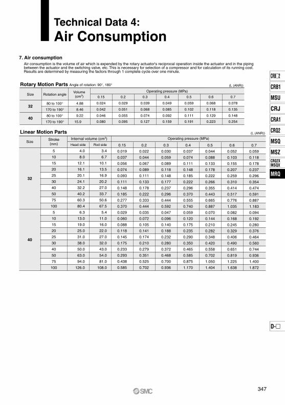
Rotary Motion Parts Angle of rotation: 90°, 180° (L (ANR))
(L (ANR))
Operating pressure (MPa)
0.15
0.024
0.042
0.046
0.080
0.2
0.029
0.051
0.055
0.095
0.3
0.039
0.068
0.074
0.127
0.4
0.049
0.085
0.092
0.159
0.5
0.059
0.102
0.111
0.191
0.6
0.068
0.118
0.129
0.223
0.7
0.078
0.135
0.148
0.254
Linear Motion Parts
5
10
15
20
25
30
40
50
75
100
5
10
15
20
25
30
40
50
75
100
4.0
8.0
12.1
16.1
20.1
24.1
32.2
40.2
60.3
80.4
6.3
13.0
19.0
25.0
31.0
38.0
50.0
63.0
94.0
126.0
3.4
6.7
10.1
13.5
16.9
20.2
27.0
33.7
50.6
67.5
5.4
11.0
16.0
22.0
27.0
32.0
43.0
54.0
81.0
108.0
0.15
0.019
0.037
0.056
0.074
0.093
0.111
0.148
0.185
0.277
0.370
0.029
0.060
0.088
0.118
0.145
0.175
0.233
0.293
0.438
0.585
0.2
0.022
0.044
0.067
0.089
0.111
0.133
0.178
0.222
0.333
0.444
0.035
0.072
0.105
0.141
0.174
0.210
0.279
0.351
0.525
0.702
0.3
0.030
0.059
0.089
0.118
0.148
0.177
0.237
0.296
0.444
0.592
0.047
0.096
0.140
0.188
0.232
0.280
0.372
0.468
0.700
0.936
0.4
0.037
0.074
0.111
0.148
0.185
0.222
0.296
0.370
0.555
0.740
0.059
0.120
0.175
0.235
0.290
0.350
0.465
0.585
0.875
1.170
0.5
0.044
0.088
0.133
0.178
0.222
0.266
0.355
0.443
0.665
0.887
0.070
0.144
0.210
0.282
0.348
0.420
0.558
0.702
1.050
1.404
0.6
0.052
0.103
0.155
0.207
0.259
0.310
0.414
0.517
0.776
1.035
0.082
0.168
0.245
0.329
0.406
0.490
0.651
0.819
1.225
1.638
0.7
0.059
0.118
0.178
0.237
0.296
0.354
0.474
0.591
0.887
1.183
0.094
0.192
0.280
0.376
0.464
0.560
0.744
0.936
1.400
1.872
Operating pressure (MPa)
Air consumption is the volume of air which is expended by the rotary actuator's reciprocal operation inside the actuator and in the piping between the actuator and the switching valve, etc. This is necessary for selection of a compressor and for calculation of its running cost.Results are determined by measuring the factors through 1 complete cycle over one minute.
Technical Data 4: Air Consumption
7. Air consumption
Size
32
40
Rotation angle
80 to 100°
170 to 190°
80 to 100°
170 to 190°
Volume(cm3)
4.88
8.46
9.22
15.9
Size
32
40
Stroke(mm)
Internal volume (cm3)
Head side Rod side
347
CRB2
CRB1
MSU
CRJ
CRA1
CRQ2
MSQ
MSZCRQ2XMSQX
MRQ
D-
MRQ

Model: MRQBS32-50CA-A73 Operating pressure: 0.5MPa
Calculate the amount of air requirement for A, B, C and D respectively.A = 0.06 x 40.2 x {(0.5 + 0.1)/0.1}/0.5 = 28.9L/minB = 0.06 x 4.88 x {(0.5 + 0.1)/0.1}/0.5 = 3.5L/minC = B = 3.5L/minD = 0.06 x 33.7 x {(0.5 + 0.1)/0.1}/0.5 = 24.3L/minSince operation is simultaneous at C and D, total the respective amounts of airrequirement.C + D = 3.5 + 24.3 = 27.8L/minOperating time (S)
Rotary motionparts
Linear motionparts
0 1 2
A D
B C
The required air volume, which is the amount of air that is required for operating the rotary cylinder at the prescribed speed, is necessary for selecting the F.R.L. equipment or the pipe size.The amount of air requirement of rotary actuator = 0.06 x V x (P/0.1)/t L /min(ANR)V : Inner volume = cm3
P : Absolute pressure = {Operating pressure (MPa) + 0.1}t : Operating time = s
8. Required air volume
Calculate the required air volume separately for the linear motion part and the rotary motion part. The required air volume for operating the linear motion and rotary motion parts simultaneously is the total of the individually obtained values.Calculation example: Obtain the required air volumes to be used from the operation chart shown below.
Technical Data 5: Required Air Volume
348

Number ofauto switches
Made to Order orport type
012
0
—
SO2O
1
OSSS2S
2
O2S2Nil
Auto switchNil Without auto switch (built-in magnet)
NilX
AB
Rotation angle
3240
Size/Standard stroke (mm)
∗ Refer to pages 360 and 361 for middle and long strokes other than standard stroke.
32MRQ B S 50 C A J79W
Mounting typeF: Flange on the rod sideB: Basic type
5, 10, 15, 20, 25, 30, 40, 50, 75, 100
80 to 100°170 to 190°
CN
Air cushionWith air cushion on the linear motion partsWithout air cushion on the linear motion parts
StandardMade to Order
Special functionTypeWiring
(Output)Electrical
entry
Load voltage
DC AC
–
–
200 V
100 V
100 V or less
–
–
5 V, 12 V
12 V
5 V, 12 V
12 V
5 V, 12 V
5 V
–
12 V
–
24 V
–
–
24 V
3-wire (NPN)
3-wire (PNP)
2-wire
3-wire (NPN)
3-wire (PNP)
2-wire
4-wire (NPN)
3-wire (NPN equivalent)
2-wire
–
Diagnostic indicator (2-color)
Water resistant (2-color)
Diagnosis output (2-color)
–
Diagnostic indicator (2-color)
Grommet
Connector
Grommet
Grommet
Connector
Grommet
Auto switch model Pre-wiredconnector
Perpendicular
0.5(Nil)
3 (L)
5 (Z)
None(N)
–
–
–
–
–
–
–
–
–
–
–
–
–
–
–
–
–
–
–
–
–
–
IC circuit
–
IC circuit
–
IC circuit
IC circuit
–
IC circuit
–
IC circuit
–
Relay,
PLC
–
Relay,
PLC
–
–
–
–
In-line
Lead wire length (m) *Applicable
load
Applicable Auto Switches (Common for the linear and the rotary motion parts)/Refer to pages 797 to 850 for further information on auto switches.
F7NV
F7PV
F7BV
J79C
F7NWV–
F7BWV
F7BAV∗∗
–
–
A72
A73
A80
A73C
A80C
A79W
F79
F7P
J79–
F79W
F7PW
J79W
F7BA∗∗
F79F
A76H
A72H
A73H
A80H
–
–
–
NilXF∗XN∗
Rc 1/8G 1/8
NPT 1/8
RotationLinearmotion
Indi
cato
r lig
ht
∗ Lead wire length symbols: ∗ Solid state auto switches marked with “” are manufactured upon receipt of order.
∗ Refer to pages 837 and 838 for detailed solid state auto switches with pre-wired connectors.
∗∗ Although it is possible to mount water resistant type auto switches, note that the rotary actuator itself is not of water resistant construction.
• Since other auto switches are available other than those listed above, refer to page 358 for details on other applicable auto switches. ∗ Auto switch is shipped together (not assembled).
0.5 m 3 m 5 m None··········
········· ········· ·········
NilLZN
(Example) A73C(Example) A73CL(Example) A73CZ(Example) A73CN
Ree
d a
uto
sw
itch
So
lid s
tate
au
to s
wit
ch
Yes
Yes
Yes
Yes
No
No
Rotary Cylinder
MRQ SeriesSize: 32, 40
How to Order
∗ For the applicable autoswitch model, refer to the table below.
∗ The combination with Made to Order is not available.
Refer to page 351 for theMade to Order details.
350
Fluid
Max. operating pressure (MPa)
Min. operating pressure (MPa)
Ambient and fluid temperature
Mounting
Air (Non-lube)
0.7 MPa
0.15 MPa
0 to 60°C (No freezing)
Basic type, Rod side flange type
Linear motion parts
Rotary motion parts
Piston speed
Cushion
Port size
Output torque (At 0.5 MPa)
Rotation time adjustment range
Cushion
Allowable kinetic energy
Port size
Backlash
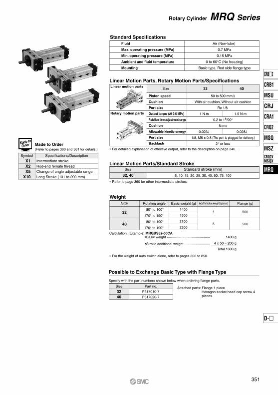
Size 32 40
50 to 500 mm/s
With air cushion, Without air cushion
Rc 1/8
1 N·m 1.9 N·m
0.2 to 1s/90°
None
0.023J 0.028J
1/8, M5 x 0.8 (The port is plugged for delivery.)
2° or less
Standard Specifications
Linear Motion Parts, Rotary Motion Parts/Specifications
Size
32, 40
Standard stroke (mm)
5, 10, 15, 20, 25, 30, 40, 50, 75, 100
Linear Motion Parts/Standard Stroke
Size
3240
Part no.
P317010-7
P317020-7
WeightSize
32
40
Rotating angle
80° to 100°
170° to 190°
80° to 100°
170° to 190°
Basic weight (g)
1400
1500
2100
2300
Add'l stroke weight (g/mm)
4
5
Flange (g)
500
500
Calculation: (Example) MRQBS32-50CA
Possible to Exchange Basic Type with Flange Type
Specify with the part numbers shown below when ordering flange parts.
Symbol Specifications/DescriptionIntermediate strokeRod-end female threadChange of angle adjustable rangeLong Stroke (101 to 200 mm)
X1X2X5
X10
Made to Order (Refer to pages 360 and 361 for details.)
Rotary Cylinder MRQ Series
∗ For detailed explanation of effective output, refer to the description on page 346.
∗ Refer to page 360 for other intermediate strokes.
•Basic weight ············································ 1400 g
•Stroke additional weight ··························
Attached parts: Flange 1 piece Hexagon socket head cap screw 4
pieces
Total 1600 g
∗ For the weight of auto switch alone, refer to pages 806 to 850.
4 x 50 = 200 g
351
CRB2
CRB1
MSU
CRJ
CRA1
CRQ2
MSQ
MSZCRQ2XMSQX
MRQ
D-
MRQ

Manufacturers of Friction Fittings/ModelSize
3240
Miki Pully Co.,Ltd. (Position lock)
PSL-K-12
PSL-K-14
ISEL Co., Ltd. (Mechanical lock)
MA-12-26
MA-14-28
∗ Please consult with manufacturers concerning further information on specifications.
Size
3240
Adjusting angle per 1 rotation of angle adjusting screw
5.7°4.8°
PrecautionsBe sure to read this before handling the products.Refer to back page 50 for Safety Instructions and pages 4 to 14 for Rotary Actuator and Auto Switch Precautions.
Caution
When pressure is applied from the arrow-marked side, the rod rotates clockwise.
B port
A port
Clockwise rotation
Friction fittings
F: Angle adjustment range ±5°
F: An
gle ad
justm
ent ra
nge ±
5°
E: An
gle ad
justm
ent ra
nge ±
5°
E: An
gle ad
justm
ent ra
nge ±
5°
Angle adjustment screw
Minimum adjustment angle 170 °Maximum adjust
ment an
gle 10
0°
Minimum adjustment
angle
80°
Maximum adjustment angle 190°
Gap
Pinion gear(Hexagonal hole)
Piston rod(Hexagonal width across flats)
The angle adjustment bolt is adjusted to a random position within the adjustable rotating range when shipped. Readjust the angle as needed before using.
Allowable Lateral Load to the Piston Rod EndUsing friction fittings makes it easier to mount the load to the piston rod end.
Note) • Can be adjusted ±5° at the rotating ends.• When the cylinder is pressurized from port B, range E can be adjusted by regulating
angle adjustment screw C.When the cylinder is pressurized from port A, range F can be adjusted by regulating angle adjustment screw D.
The rotary motion part has a structure that does not generate backlash. However, the pinion gear has a hexagonal hole, and a slight clearance exists between the hexagonal hole of the rotary motion part and the hexagonal flats of the piston rod of the linear part.This clearance generates a backlash in the rotational direction of the piston rod.
MRQ Series
Backlash
Rotating Direction Rotation Angle Adjustable Range/Rotating Angle
352

Component PartsNo.q
w
e
r
t
y
u
i
o
!0
!1
!2
!3
!4
!5
!6
!7
!8
!9
@0
@1
@2
@3
@4
@5
@6
@7
@8
@9
#0
#1
#2
#3
#4
#5
#6
#7
#8
#9
Description MaterialAluminum alloyAluminum alloyAluminum alloy
NBRAluminum alloyStainless steel
Chrome molybdenum steelResin
–Aluminum alloyAluminum alloyAluminum alloyAluminum alloyAluminum alloyAluminum alloyStainless steel
Sintered metallicAluminum alloy
NBRAluminum alloyAluminum alloy
Rolled steelAluminum alloy
NBRSteel wire
ResinChrome molybdenum steel
Magnetic materialRolled steel
ResinBrassNBRNBRNBRNBRNBRNBRNBRNBR
NoteAnodizedAnodized
Chromated
Anodized
AnodizedAnodizedAnodizedAnodized
Platinum silverChromated
Platinum silver
AnodizedAnodized
Electroless nickel platedChromated
Electroless nickel plated
BodyCoverPlateSealEnd coverPistonPinion gearWearingMagnetBearing colorSteady brace coverTubeHead coverRod coverPistonPiston rodNon-rotating guideFlangeTube gasketRod packing guideColorCushion ring O-ring retainerO-ringCushion valve assemblyWearingHexagon socket head cap screwPlastic magnetSwitch mounting nutSwitch spacerPlugRod packingPiston sealPiston sealCushion sealO-ringO-ringO-ringO-ring
Description
Component PartsNo.$0
$1
$2
$3
$4
$5
$6
$7
$8
$9
%0
%1
%2
%3
%4
%5
%6
%7
%8
MaterialStainless steelStainless steelStainless steelStainless steel
Steel wireSteel wireSteel wire
Stainless steelSteel wireSteel wireSteel wireSteel wireSteel wireSteel wire
Bearing steelBearing steelBearing steelBearing steelBearing steel
NoteHexagon socket head cap screwHexagon socket head cap screwHexagon socket head cap screwHexagon socket head cap screwRound head Phillips screwRound head Phillips screwHexagon socket head set screwCompact hexagon nutHexagon small nutSeal washerSteel ballR-shape retaining ringR-shape retaining ringR-shape retaining ringBearingBearingShell type needle roller bearingThrust needle roller bearingBearing ring
DescriptionNo.r
i
!9
@6
#2
#3
#4
#6
#8
#9
$9
Quantity14211144412
SealWearingTube gasketWearingRod packingPiston sealPiston sealO-ringO-ringO-ringSeal washer
DescriptionSize
Replacement Parts
Spare parts assembly part no.
Parts included in thespare parts
32P31701-1
40P31702-1
A grease pack (10 g) is included. When you need an additional grease pack, order using the following part number.Replacement part/Grease pack part no. : GR-S-010 (10g)∗ Individual part cannot be shipped.
∗ Part unnecessary for models without a cushion.
Rotary Cylinder MRQ Series
Construction
353
CRB2
CRB1
MSU
CRJ
CRA1
CRQ2
MSQ
MSZCRQ2XMSQX
MRQ
D-
MRQ
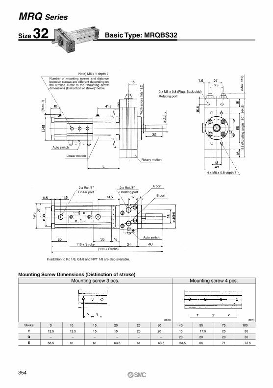
Stroke
Y
Q
E
5
12.5
–
58.5
10
12.5
–
61
15
15
–
61
20
15
–
63.5
25
20
–
61
30
20
–
63.5
40
15
20
63.5
50
17.5
20
66
75
25
20
71
100
30
30
73.5
Mounting screw 3 pcs. Mounting screw 4 pcs.
(mm) (mm)
Mounting Screw Dimensions (Distinction of stroke)
Size 32 Basic Type: MRQBS32
In addition to Rc 1/8, G1/8 and NPT 1/8 are also available.
MRQ Series
Note) M6 x 1 depth 7
Number of mounting screws and distance between screws are different depending on the strokes. Refer to the “Mounting screw dimensions (Distinction of stroke)” below.
Wid
th a
cros
s fla
ts 1
2.2
Rotary motion
Auto switch
Linear motion
2 x M5 x 0.8 (Plug, Back side)Rotating port
Rotating port
113
(Rot
atin
g an
gle
180°
: 144
.5)
4 x M5 x 0.8 depth 7
Linear port2 x Rc1/8∗ 2 x Rc1/8∗ A port
B port
116 + Stroke(198 + Stroke)
Auto switch(M
ax. ≅
12)
(Max
. 7)
354

Stroke
Y
Q
E
5
12.5
–
58.5
10
12.5
–
61
15
15
–
61
20
15
–
63.5
25
20
–
61
30
20
–
63.5
40
15
20
63.5
50
17.5
20
66
75
25
20
71
100
30
30
73.5
Mounting screw 3 pcs. Mounting screw 4 pcs.
(mm) (mm)
Mounting Screw Dimensions (Distinction of stroke)
Flange Type: MRQFS32
In addition to Rc 1/8, G1/8 and NPT 1/8 are also available.
Rotary Cylinder MRQ Series
4 x 6.6 through
A port
B port
Wid
th a
cros
s fla
ts 1
2.2
Auto switch
Auto switch
Linear motion
113
(Rot
atin
g an
gle
180°
: 144
.5)
116 + Stroke
(198 + Stroke)
Note) M6 x 1 depth 7
Number of mounting screws and distance between screws are different depending on the strokes. Refer to the “Mounting screw dimensions (Distinction of stroke)” below.
Rotary motion
2 x M5 x 0.8 (Plug, Back side)Rotating port
Rotating portLinear port
(Max
. ≅12
)
(Max
. 7)
2 x Rc1/8∗ 2 x Rc1/8∗
355
CRB2
CRB1
MSU
CRJ
CRA1
CRQ2
MSQ
MSZCRQ2XMSQX
MRQ
D-
MRQ

Stroke
Y
Q
E
5
12.5
–
68
10
15
–
68
15
15
–
70.5
20
20
–
68
25
20
–
70.5
30
15
20
68
40
17.5
20
70.5
50
17.5
20
75.5
75
25
20
80.5
100
30
30
83
Mounting screw 3 pcs. Mounting screw 4 pcs.
(mm) (mm)
Mounting Screw Dimensions (Distinction of stroke)
In addition to Rc 1/8, G1/8 and NPT 1/8 are also available.
Size 40 Basic Type: MRQBS40
MRQ Series
Note) M6 x 1 depth 7
Number of mounting screws and distance between screws are different depending on the strokes. Refer to the “Mounting screw dimensions (Distinction of stroke)” below.
Wid
th a
cros
s fla
ts 1
4.2
Auto switch
Auto switch
Linear motion
Rotary motion
132
(Rot
atin
g an
gle
180°
: 170
)
4 x M6 x 1 depth 7
A port
B port
128.5 + Stroke
216.5 + Stroke(M
ax. ≅
11.5
)
2 x M5 x 0.8 (Plug, Back side)Rotating port
Rotating portLinear port
(Max
. 7)
2 x Rc1/8∗ 2 x Rc1/8∗
356

Stroke
Y
Q
E
5
12.5
–
68
10
15
–
68
15
15
–
70.5
15
15
–
70.5
25
20
–
70.5
30
15
20
68
40
17.5
20
70.5
50
17.5
20
75.5
75
25
20
80.5
100
30
30
83
Mounting screw 3 pcs. Mounting screw 4 pcs.
(mm) (mm)
Mounting Screw Dimensions (Distinction of stroke)
In addition to Rc 1/8, G1/8 and NPT 1/8 are also available.
Flange Type: MRQFS40
Note) M6 x 1 depth 7
Number of mounting screws and distance between screws are different depending on the strokes. Refer to the “Mounting screw dimensions (Distinction of stroke)” below.
Auto switch
Linear motion
Rotary motion
2 x M5 x 0.8 (Plug, Back side)Rotating port
4 x 6.6 through
132
(Rot
atin
g an
gle
180°
: 170
)
A port
B port
128.5 + Stroke
216.5 + Stroke
Auto switch
Wid
th a
cros
s fla
ts 1
4.2
(Max
. ≅11
.5)
Rotary Cylinder MRQ Series
Rotating portLinear port
(Max
. 7)
2 x Rc1/8∗ 2 x Rc1/8∗
357
CRB2
CRB1
MSU
CRJ
CRA1
CRQ2
MSQ
MSZCRQ2XMSQX
MRQ
D-
MRQ

The values in (parentheses) are of D-A72, A7 H, A80H
Linearmotion parts
Rotarymotion parts
Linear motion parts Size
324032403240
6
1
9 11.5
D-F79F
8 7
1
9 11.5
Rotary motion parts RotatingangleSize
32403240
32
40
28 27 4 3
25 32.532 41.5
D-F79F
40 32 7 4
29 36.536 45.5
D-F7, F7V, J79, J79C, F7W, F7 WV, J79W, F7BA, F7BAV
D-F7, F7V, J79, J79C, F7W, F7WV, J79W, F7BA, F7BAV
BQ-2
Linear motion parts
In addition to the applicable auto switches indicated in How to Order, the following auto switches can be also mounted.Refer to page 826 concerning further information on specifications of the auto switch single body.
Solid stateAuto switch type Part no.
D-F7NTElectrical entry (Fetching direction)
Grommet (In-line) With timerFeature
Auto switch mounting rail
Auto switch mounting spacer
Auto switch mounting screw
Auto switch
Slide the auto switch mounting spacer and place it on the auto switch mounting position of the body. (At this time, verify that the auto switch mounting nut that is inserted in the auto switch mounting rail is placed simultaneously in the auto switch mounting position.)Engage the tongue portion of the auto switch mounting arm into the groove portion of the auto switch mounting spacer.Lightly screw the auto switch mounting screw into the auto switch mounting nut, via the hole in the auto switch mounting arm.After verifying the detection position, tighten the mounting screw to secure the auto switch in place. (The tightening torque of the M3 screw is approximately 0.5 N·m.)The detection position can be changed under the conditions described in step e.
The value of the individual auto switch’s movement range Lm converted into the shaft's rotation angle
The value of the auto switch’s hysteresis as represented by an angle
Auto switch mounting bracket part no.
∗ Common for MRQ32 and 40
1.
2.
3.
4.
5.
MRQ Series
With Auto Switch
D-A7/A8
12 11
2
8.5(9)11(11.5)
Operating range(mm)
Hysteresis(mm)
Proper mounting position A (mm)
80 to 100°170 to 190°
80 to 100°170 to 190°
D-A7/A8
55 46 10 7
24.5 (25)32 (32.5)31.5 (32)41 (41.5)
Operating range(Degree)
Hysteresis angle(Degree)
Proper mounting position B
(mm)
Operating range within proper mounting position (Lm/2)
Operating range of auto switch single body (Lm)
Most sensitive position
Nut for fixing
Operatingangle
Hysteresis angle
:
:
Note) Since the above values are only provided as a guideline, they are not guaranteed. In the actual setting, adjust them after confirming the auto switch performance.
Applicable Auto Switch
Refer to pages 806 to 850 concerning further information on specifications of the auto switch single body.
Operating Range/Hysteresis/Proper Mounting Positions of Auto Switch
Mounting and Moving Method of Auto Switch
358

Solid state switch
D-A7/A80
D-F7/F7F/F7BAL/F7NT/J79
D-F7V
D-J79C D-F7W/J79W
(In parentheses) are the dimensions of “A72”.
D-A79W
D-A7H D-A73C/A80C
CautionBe sure to read pages 800 to 804 before handling the products when using auto switches.
Reed switch
Rotary Cylinder With Auto Switch MRQ Series
Auto Switch Mounting Dimensions
359
CRB2
CRB1
MSU
CRJ
CRA1
CRQ2
MSQ
MSZCRQ2XMSQX
MRQ
D-
MRQ

Size
32
40
Stroke 1 to 4 6 to 911 to 1416 to 1921 to 2426 to 2931 to 3941 to 4951 to 6566 to 7476 to 9091 to 99 1 to 4 6 to 911 to 1416 to 1921 to 2426 to 2931 to 3941 to 4951 to 6566 to 7476 to 9091 to 99
Y
12.5
15
20
15 17.5
25
30
12.5
15
20
15
17.5
25
30
Q
20
20
30
30
58.5 – ( 5 – Stroke)/2 61 – ( 10 – Stroke)/2 61 – ( 15 – Stroke)/2 63.5 – ( 20 – Stroke)/2 61 – ( 25 – Stroke)/2 63.5 – ( 30 – Stroke)/2 63.5 – ( 40 – Stroke)/2 66 – ( 50 – Stroke)/2 66 – ( 65 – Stroke)/2 71 – ( 75 – Stroke)/2 68.5 – ( 90 – Stroke)/2 73.5 – ( 100 – Stroke)/2 68 – ( 5 – Stroke)/2 68 – ( 10 – Stroke)/2 70.5 – ( 15 – Stroke)/2 68 – ( 20 – Stroke)/2 70.5 – ( 25 – Stroke)/2 68 – ( 30 – Stroke)/2 70.5 – ( 40 – Stroke)/2 75.5 – ( 50 – Stroke)/2 75.5 – ( 65 – Stroke)/2 80.5 – ( 75 – Stroke)/2 78 – ( 90 – Stroke)/2 83 – ( 100 – Stroke)/2
E Mounting screw
3
4
3
4
(mm)
Size3240
S116
128.5
ZZ198
216.5
Size
3240
Part no.
P317010-13
∗ One set of the actuator requires two sets of the hexagon socket head cap screws.
Size3240
LMax. 32 Max. 31.5
(mm)
Mounting Screw Dimensions (Distinction of stroke)
Intermediate StrokeSymbol
-X11 Rod End Female ThreadSymbol
-X22
Non-standard Angle Adjustment RangeSymbol
-X53
Please contact SMC for detailed dimensions, specifications and lead times.
MRQ Series
Made to Order Specifications
M6 x 1 depth 7Number of mounting screws and distance between screws are different depending on the strokes. Refer to the “Mounting screw dimensions (Distriction of stroke)” below.
For intermediate strokes other than standard strokes, the full length is shortened by cutting the linear motion side according to the stroke.
MRQ Mounting Stroke Cushion Auto switchRotatingangleS X X132
40
Intermediate strokeOperating stroke
S + Stroke
ZZ + Stroke
M6 x 1 effective depth 12
Mounting screw 3 pcs. Mounting screw 4 pcs.
Angle adjustment screw
MRQ Stroke Cushion Auto switchS X X23240
Rod end female thread
Mounting Rotatingangle
MRQ Mounting Stroke Cushion Auto switchRotatingangleS X X532
40
Angle adjustment range
∗
∗ For rotating angle, fill in either A (90° type) or B (180° type). The standard angle adjustment range of ±5° (one side) is changed to in this type.+ 5°
–95°
Possible to Change the Specifications from the Basic Type to “-X5”
Attached parts: Hexagon socket head cap screw 1 pc.Hexagon nut with flange 1 pc.Seal washer 1 pc.
Specify the part number for hexagon socket head cap screw for angle adjustment referring to the list below.
360

Long Stroke (101 to 200 mm)Symbol
-X104
Stroke
105
110
115
120
125
130
140
150
175
200
F(N)
9
8
7
5
F(N)
15
14
13
12
11
Size 32 Size 40
Acceptable Side Loading to the Tip of Piston Rod F
0
1
2
n
–
S0
20
n0
0S
SS
2S
nS
02
S2
Nil
n2
0 1 2Number of Auto Switches Mounted
4 x M6 x 1 depth 7
Formula for “E” dimensions
Size 32(Stroke – 100)/2 + 73.5
Size 40(Stroke – 100)/2 + 83
MRQ Mounting Stroke Cushion Auto switchRotatingangleS X X1032
40
Long strokeOperating stroke
Set at the closer factors to those indicated in the table for the acceptable side loading of strokes not indicated in the table.
∗ Refer to the table of number of the auto switches mounted below.
Rotation angleLinear motion
Combinations of made-to-order products No. 1 to 4 are available. Please contact SMC for further information.
Made to Order Specifications MRQ Series
361
CRB2
CRB1
MSU
CRJ
CRA1
CRQ2
MSQ
MSZCRQ2XMSQX
MRQ
D-
MRQ


