8/28/2012
1
Greg Wohl Ph.D., P.Eng.
Department of Mechanical Engineering
McMaster School of Biomedical Engineering
Musculoskeletal
Biomechanics
Suggested Reading [including McMaster Health Sciences Library call numbers]
• Einhorn TA, O’Keefe RJ, Buckwalter JA, eds. Orthopaedic Basic Science:
Foundations of Clinical Practice, 3rd Edtion. AAOS. 2007 [WE 102 .O77 2007]
• Buckwalter JA, Einhorn TA, Simon SR, eds. Orthopaedic Basic Science: Biology
and Biomechanics of the Musculoskeletal System, 2nd Edtion. AAOS. 2000.
[WE 102 .O77 2000]
• Bartel DL, Davy DT, Keaveny TM. Orthopaedic Biomechanics: Mechanics and
Design in Musculoskeletal Systems. Pearson Prentice Hall Bioengineering. 2006.
[WE 102 .B283O 2006]
• Nordin M, Frankel VH, eds. Basic Biomechanics of the Musculoskeletal System.
Lippincott Williams & Wilkins. 2001. [WE 103 .B311 2001]
• Mow VC, Huiskes R, eds. Basic Orthopaedic Biomechanics & Mechano-biology,
3rd Edition. Lippincott Williams & Wilkins. 2005. [WE 103 .B3125 2005]
Musculoskeletal Biomechanics
I. Joint Mechanics
II. Material Properties and Behaviours• stress, strain, elastic modulus
• wear and fatigue
• directional properties (anisotropy)
• viscoelasticity
III. Examples of Bone Adaptation in Aging and Repair• Aging – bone geometry and structural properties
• Repair – the effect of implant modulus on bone adaptation
I. Joint Mechanics
• Mechanical “advantage” (levers, moments)
• Joint structures and dynamics
• Determination of joint loading
• Example of novel measurement techniques
Mechanical AdvantageLevers — Moments (Torque)
F F
2F
M1
M1 = F • L
M2
M2 = F • L
L L
M1 = 2F • L M2 = F • L
M1 = 2F • L/2 M2 = F • L
L/2
=
≠
=
3.3 cm
30 cm
Diarthrodial Joint MomentsMuscle – Joint Loads
a
b
Mw
Mw = Fw • 30 cm
Mm
Mm = Fm • 3.3 cm
Mw = MmEquilibrium:
b ≈ 9 • aGeometry:
Fw
Fm
FJ
Loads: Fm ≈ 9 • Fw
FJ = 8 • Fw
Load
Equilibrium:Fm = Fw + FJ
8/28/2012
2
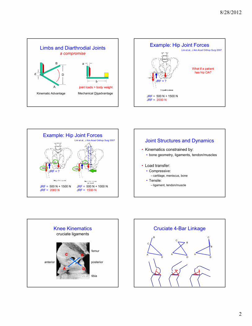
Limbs and Diarthrodial Jointsa compromise
A
B
d D
Kinematic Advantage
a
b
Mechanical Disadvantage
joint loads > body weight
Example: Hip Joint ForcesLim et al., J Am Acad Orthop Surg 2007
JRF = 500 N + 1500 N
JRF = 2000 N
What if a patient
has hip OA?
JRF = ?
Example: Hip Joint ForcesLim et al., J Am Acad Orthop Surg 2007
JRF = 500 N + 1500 N
JRF = 2000 N
JRF = ?
JRF = 500 N + 1000 N
JRF = 1500 N
Joint Structures and Dynamics
• Kinematics constrained by:
• bone geometry, ligaments, tendon/muscles
• Load transfer:
• Compressive:
– cartilage, meniscus, bone
• Tensile:
– ligament, tendon/muscle
Knee Kinematics cruciate ligaments
CC
DD
BB
AA
femur
tibia
anterior posterior
Cruciate 4-Bar Linkage
DA
C
B
A
D
BC
A
D
C
B
8/28/2012
3
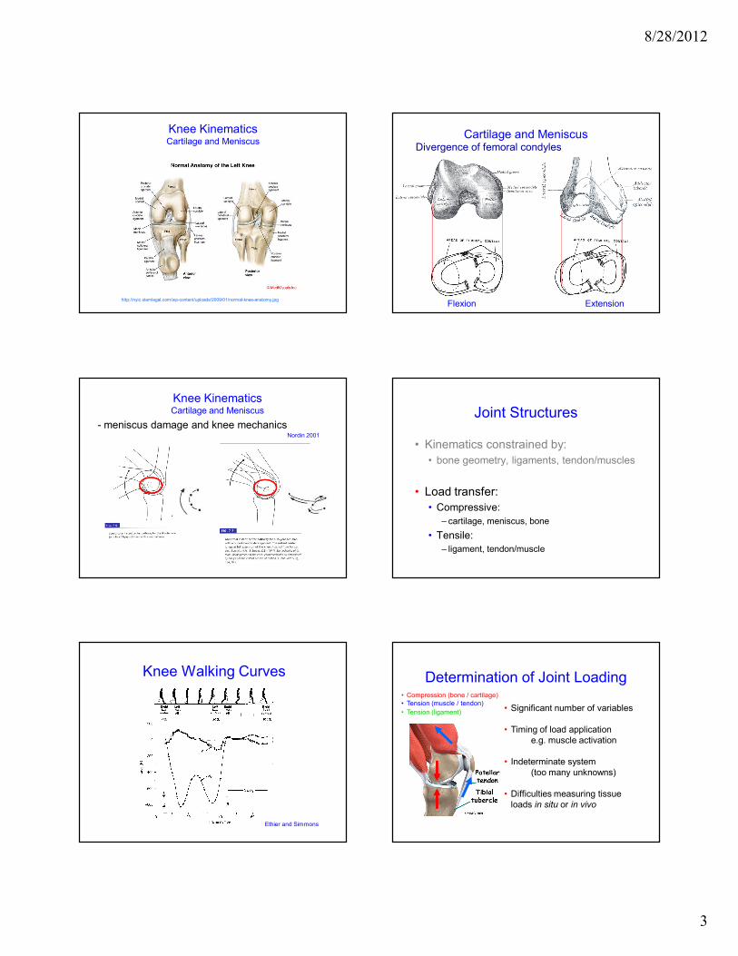
http://nyic.stemlegal.com/wp-content/uploads/2009/01/normal-knee-anatomy.jpg
Knee Kinematics Cartilage and Meniscus
ExtensionFlexion
Divergence of femoral condyles
Cartilage and Meniscus
Nordin 2001
- meniscus damage and knee mechanics
Knee Kinematics Cartilage and Meniscus Joint Structures
• Kinematics constrained by:
• bone geometry, ligaments, tendon/muscles
• Load transfer:
• Compressive:
– cartilage, meniscus, bone
• Tensile:
– ligament, tendon/muscle
Knee Walking Curves
Ethier and Simmons
Determination of Joint Loading
• Significant number of variables
• Timing of load application
e.g. muscle activation
• Indeterminate system
(too many unknowns)
• Difficulties measuring tissue
loads in situ or in vivo
• Compression (bone / cartilage)
• Tension (muscle / tendon)
• Tension (ligament)
8/28/2012
4
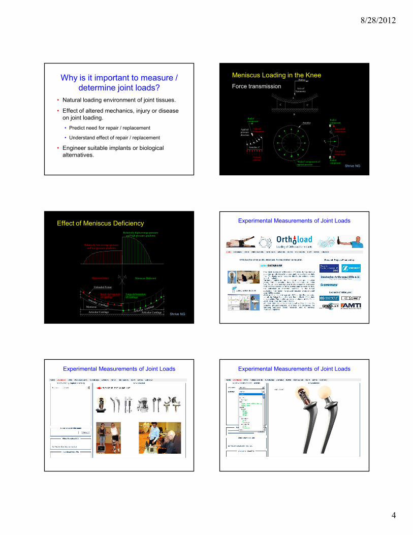
Why is it important to measure /
determine joint loads?
• Natural loading environment of joint tissues.
• Effect of altered mechanics, injury or disease
on joint loading.
• Predict need for repair / replacement
• Understand effect of repair / replacement
• Engineer suitable implants or biological
alternatives.
Radius
Axis of
Symmetry
A
CC
B
Annulus
"Radial" components of
applied pressure
Fr
Fc Tangential
component
Radial
component
Tangentialcomponent
Radial
component
cF
Annulus, C
Verticalcomponent
Radial
component
Applied pressure
direction
Vertical
reaction
Force transmission
Shrive NG
Meniscus Loading in the Knee
Meniscus
ArticularCartilage
Articular Cartilage
Unloaded Femur
Meniscus Intact Meniscus Deficient
Small deformation
of cartilage
Articular CartilageArticular Car
tilage
Large deformation
of cartilage
Relatively high average pressure
and high pressure gradients
Relatively low average pressure
and low pressure gradients
Effect of Meniscus Deficiency
Shrive NG
Experimental Measurements of Joint Loads
Experimental Measurements of Joint Loads Experimental Measurements of Joint Loads

8/28/2012
5
Experimental Measurements of Joint Loads
Musculoskeletal Biomechanics
I. Joint Mechanics
II. Material Properties and Behaviours• stress, strain, elastic modulus
• wear and fatigue
• directional properties (anisotropy)
• viscoelasticity
III. Examples of Bone Adaptation in Aging and Repair• Aging – bone geometry and structural properties
• Repair – the effect of implant modulus on bone adaptation
II. Material Properties & Behaviour
1. Material properties (e.g., stress, strain)
2. Wear and Fatigue
3. Directional properties (anisotropy)
4. ViscoelasticityENERGY
Mechanical Tests: Tensile Test — Bone
LO
AD
[N
]
DEFORMATION [mm]
AA
BB CCDD
D1D1
ULTIMATE
FAILURE
POINT
ELASTIC
REGION
(stiffness)
PLASTIC REGION
YIELD
POINT
1) Material Properties
and energy (toughness)
LO
AD
[N
]
DEFORMATION [mm]
ceramic
aluminum
Brittle: PMMA
ceramic
bone
Ductile: aluminum
stainless steel
cobalt-chromium
bone
Ductile vs. Brittle Properties
Intermediate:
titanium
Structural (Architectural) Effects
LO
AD
[N
]
DEFORMATION [mm]
2) Material Properties
Load and Deformation are Structural Properties
- they depend on both geometric and material properties
8/28/2012
6
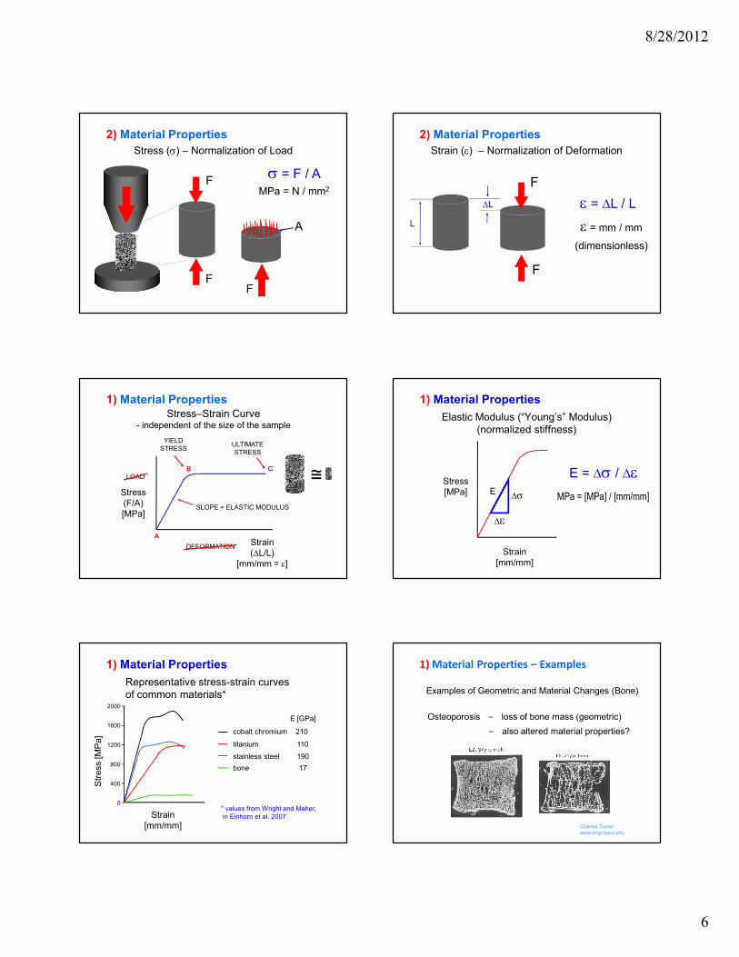
Stress (σ) – Normalization of Load
F
F
σ = F / A
MPa = N / mm2
F
A
2) Material Properties
Strain (ε) – Normalization of Deformation
F
F
L
∆L ε = ∆L / L
ε = mm / mm
(dimensionless)
2) Material Properties
Stress–Strain Curve- independent of the size of the sample
LOAD
DEFORMATION
AA
BB CC
ULTIMATE
STRESS
YIELD
STRESS
Stress
(F/A)
[MPa]
Strain
(∆L/L)
[mm/mm = ε]
SLOPE = ELASTIC MODULUS
≅
1) Material Properties
Elastic Modulus (“Young’s” Modulus)
(normalized stiffness)
Stress
[MPa]
Strain
[mm/mm]
∆ε
∆σE
E = ∆σ / ∆ε
MPa = [MPa] / [mm/mm]
1) Material Properties
Representative stress-strain curves
of common materials*
1) Material Properties
Str
ess [M
Pa]
Strain
[mm/mm]
cobalt chromium 210
titanium 110
stainless steel 190
bone 17
E [GPa]
2000
1600
0
1200
800
400
* values from Wright and Maher,
in Einhorn et al. 2007
1) Material Properties – Examples
Examples of Geometric and Material Changes (Bone)
Osteoporosis ⎯ loss of bone mass (geometric)
⎯ also altered material properties?
Charles Turner
www.engr.iupui.edu
8/28/2012
7
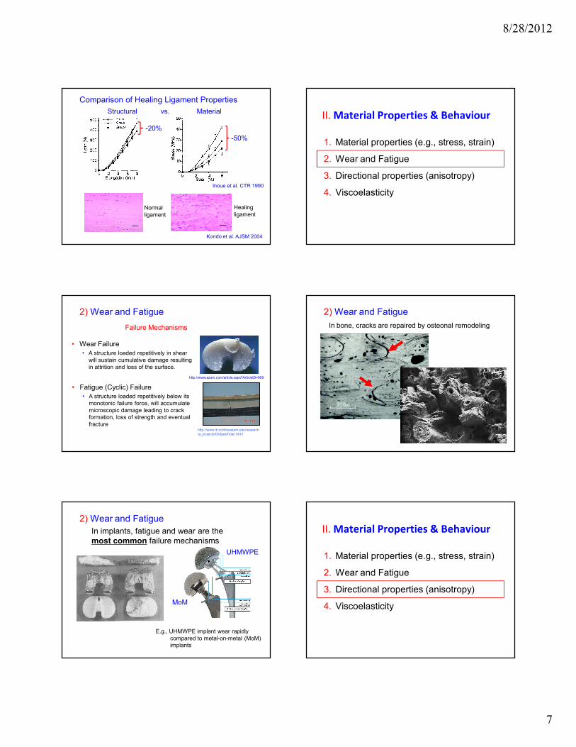
Kondo et al. AJSM 2004
Normal
ligament
Healing
ligament
Comparison of Healing Ligament Properties
Inoue et al. CTR 1990
-20%
-50%
Structural vs. Material II. Material Properties & Behaviour
1. Material properties (e.g., stress, strain)
2. Wear and Fatigue
3. Directional properties (anisotropy)
4. Viscoelasticity
• Wear Failure
• A structure loaded repetitively in shear
will sustain cumulative damage resulting
in attrition and loss of the surface.
http://www.iti.northwestern.edu/research
/a_projects/bridges/hoan.html
2) Wear and Fatigue
Failure Mechanisms
http://www.azom.com/article.aspx?ArticleID=909
• Fatigue (Cyclic) Failure
• A structure loaded repetitively below its
monotonic failure force, will accumulate
microscopic damage leading to crack
formation, loss of strength and eventual
fracture
2) Wear and Fatigue
In bone, cracks are repaired by osteonal remodeling
2) Wear and Fatigue
In implants, fatigue and wear are the
most common failure mechanisms
E.g., UHMWPE implant wear rapidly
compared to metal-on-metal (MoM)
implants
UHMWPE
MoM
II. Material Properties & Behaviour
1. Material properties (e.g., stress, strain)
2. Wear and Fatigue
3. Directional properties (anisotropy)
4. Viscoelasticity
8/28/2012
8
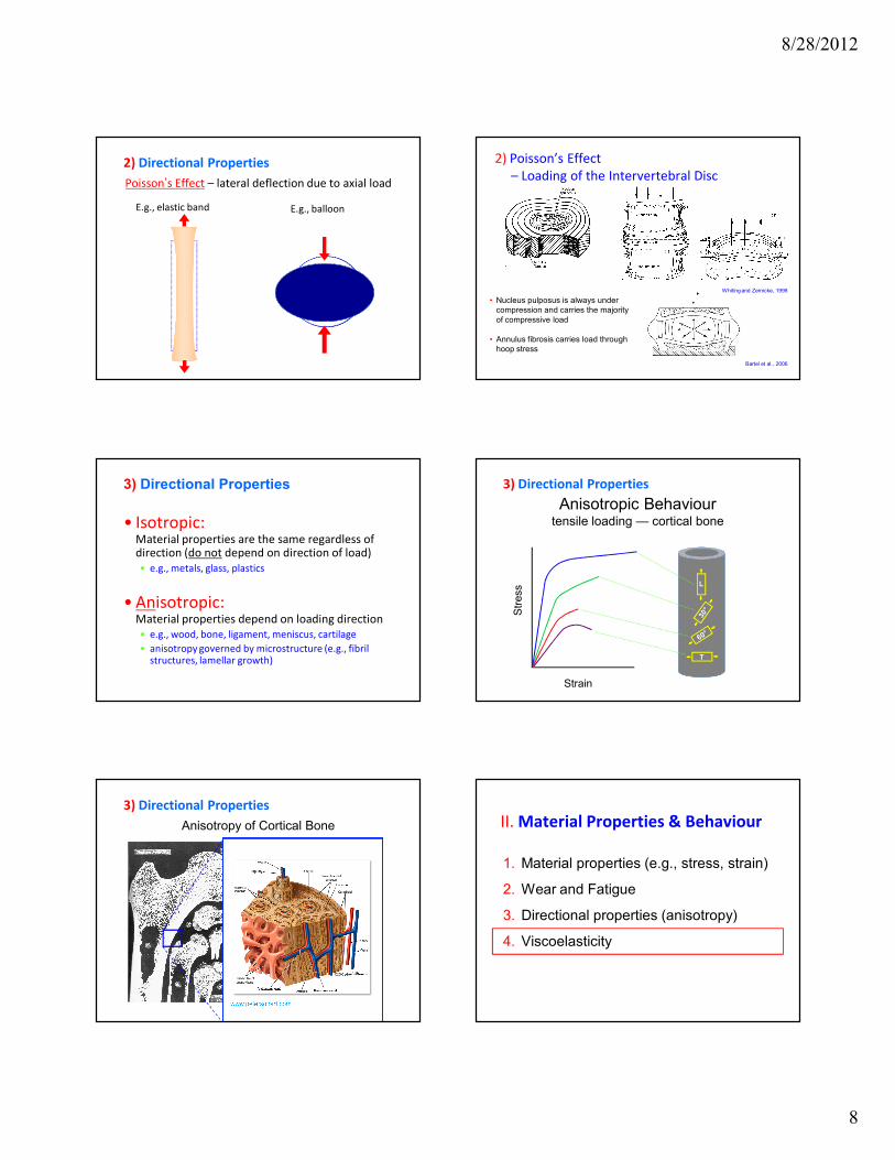
Poisson’s Effect – lateral deflection due to axial load
2) Directional Properties
E.g., elastic band E.g., balloon
2) Poisson’s Effect
– Loading of the Intervertebral Disc
• Nucleus pulposus is always under
compression and carries the majority
of compressive load
• Annulus fibrosis carries load through
hoop stress
Whiting and Zernicke, 1998
Bartel et al., 2006
3) Directional Properties
• Isotropic:Material properties are the same regardless of direction (do not depend on direction of load)
• e.g., metals, glass, plastics
• Anisotropic:Material properties depend on loading direction
• e.g., wood, bone, ligament, meniscus, cartilage
• anisotropy governed by microstructure (e.g., fibril structures, lamellar growth)
Anisotropic Behaviourtensile loading — cortical bone
Str
ess
Strain
L
T
3) Directional Properties
Anisotropy of Cortical Bone
3) Directional Properties
II. Material Properties & Behaviour
1. Material properties (e.g., stress, strain)
2. Wear and Fatigue
3. Directional properties (anisotropy)
4. Viscoelasticity
8/28/2012
9
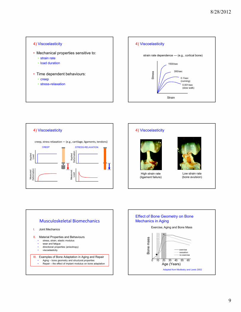
• Mechanical properties sensitive to:
• strain rate
• load duration
• Time dependent behaviours:
• creep
• stress-relaxation
4) Viscoelasticity
Str
ess
Strain
1500/sec
300/sec
0.1/sec
(running)
0.001/sec
(slow walk)
strain rate dependence — (e.g., cortical bone)
4) Viscoelasticity
creep, stress relaxation — (e.g., cartilage, ligaments, tendons)
Me
asu
red
De
form
atio
nA
pp
lied
Lo
ad
CREEP
Me
asu
red
Lo
ad
Ap
plie
d
De
form
atio
n
STRESS-RELAXATION
4) Viscoelasticity
High strain rate
(ligament failure)
Low strain rate
(bone avulsion)
Strain-Rate Dependence – Bone
4) Viscoelasticity
Musculoskeletal Biomechanics
I. Joint Mechanics
II. Material Properties and Behaviours• stress, strain, elastic modulus
• wear and fatigue
• directional properties (anisotropy)
• viscoelasticity
III. Examples of Bone Adaptation in Aging and Repair• Aging – bone geometry and structural properties
• Repair – the effect of implant modulus on bone adaptation
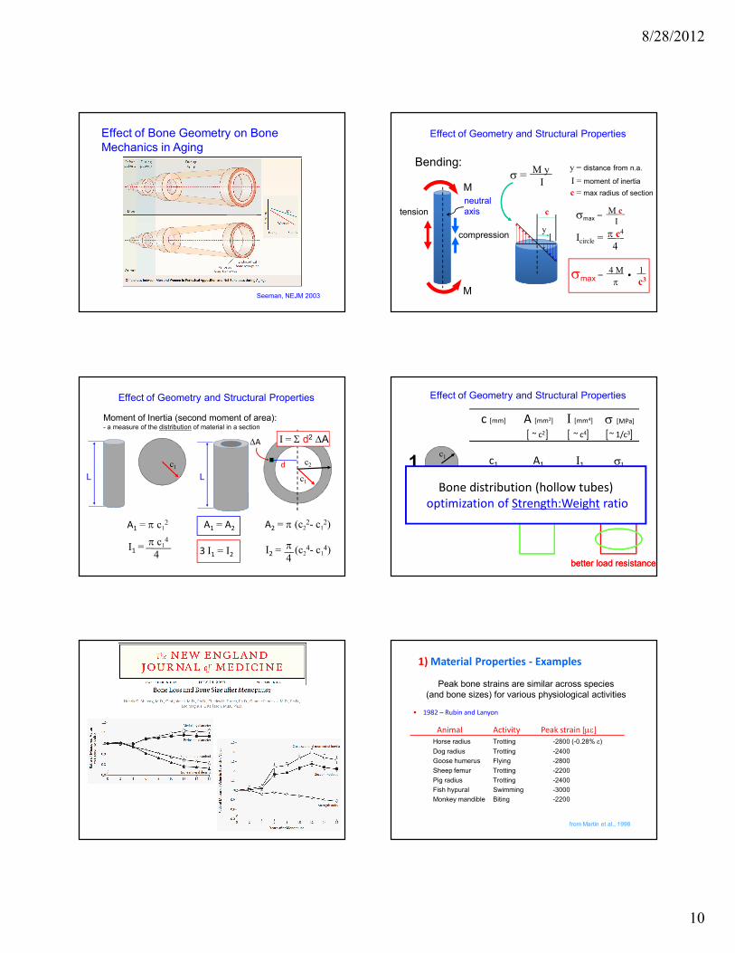
Effect of Bone Geometry on Bone
Mechanics in Aging
Age (Years)
Bon
e m
ass
0 10 20
exercise
cessation
no exercise
30 40 50 60
����
x
Adapted from Modlesky and Lewis 2002
Exercise, Aging and Bone Mass
8/28/2012
10
Effect of Bone Geometry on Bone
Mechanics in Aging
Seeman, NEJM 2003
Effect of Geometry and Structural Properties
Bending:
tension
compression
M
M
neutral
axis c
c = max radius of section
I = moment of inertia
Icircle =π c4
4
σmax = �4 M 1
π c3
σmax =M c
I
y = distance from n.a.
y
σ =M y
I
c1
c2
Moment of Inertia (second moment of area):- a measure of the distribution of material in a section
c1
L L
A1 = π c12 A2 = π (c2
2- c12)
d
I1 =π c1
4
4 I2 = (c24- c1
4)π
4 3 I1 = I2
A1 = A2
∆A I = Σ d2 ∆A
Effect of Geometry and Structural Properties
c2
c [mm] A [mm2] I [mm4] σ [MPa]
~ c2 ~ c4 ~ 1/c3
c1 A1 I1 σ1
c1
2
A1
2
I1
42.8 σ1
c1
2
A1
2
3 I1
41.3 σ1
1
2
3c2
c1
c1
c1 ,
same amount of material same amount of material
better load resistancebetter load resistance
Bone distribution (hollow tubes)
optimization of Strength:Weight ratio
Effect of Geometry and Structural Properties
1) Material Properties - Examples
• 1982 – Rubin and Lanyon
Animal Activity Peak strain [µε]
Horse radius Trotting -2800 (-0.28% ε) Dog radius Trotting -2400 Goose humerus Flying -2800 Sheep femur Trotting -2200 Pig radius Trotting -2400 Fish hypural Swimming -3000 Monkey mandible Biting -2200
Peak bone strains are similar across species
(and bone sizes) for various physiological activities
from Martin et al., 1998
8/28/2012
11
Stress
[MPa]
Strain [mm/mm]
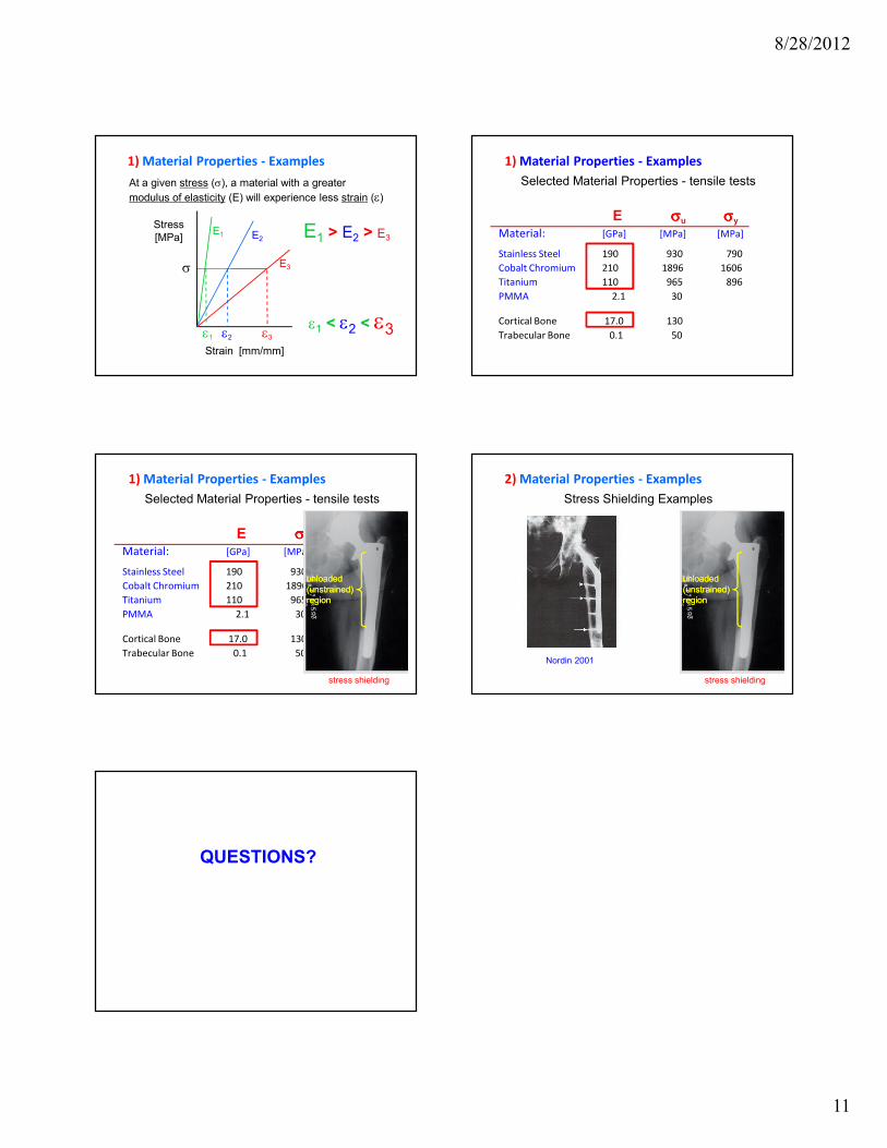
1) Material Properties - Examples
At a given stress (σ), a material with a greater
modulus of elasticity (E) will experience less strain (ε)
E1 E2
E3
E1 > E2 > E3
ε1
σ
ε2 ε3
ε1 < ε2 < ε3
Selected Material Properties - tensile tests
E σσσσu σσσσy
Material: [GPa] [MPa] [MPa]
Stainless Steel 190 930 790
Cobalt Chromium 210 1896 1606
Titanium 110 965 896
PMMA 2.1 30
Cortical Bone 17.0 130
Trabecular Bone 0.1 50
1) Material Properties - Examples
Selected Material Properties - tensile tests
E σσσσu σσσσy
Material: [GPa] [MPa] [MPa]
Stainless Steel 190 930 790
Cobalt Chromium 210 1896 1606
Titanium 110 965 896
PMMA 2.1 30
Cortical Bone 17.0 130
Trabecular Bone 0.1 50
1) Material Properties - Examples
stress shielding
unloaded
(unstrained)
region
unloaded
(unstrained)
region
Stress Shielding Examples
2) Material Properties - Examples
stress shielding
unloaded
(unstrained)
region
unloaded
(unstrained)
region
Nordin 2001
QUESTIONS?


![[OS 203] Basic Biomechanics of Musculoskeletal System.pdf](https://cdn.vdocument.in/doc/165x107/577cd6b11a28ab9e789cfe39/os-203-basic-biomechanics-of-musculoskeletal-systempdf.jpg)

