
Natural and Metamaterial Low-profile Antennas
with Emphasis on Realization of Wideband Characteristics
- Antenna Height from l/4 to l/100 -
H. NAKANO
Hosei University
Tokyo
Japan
1
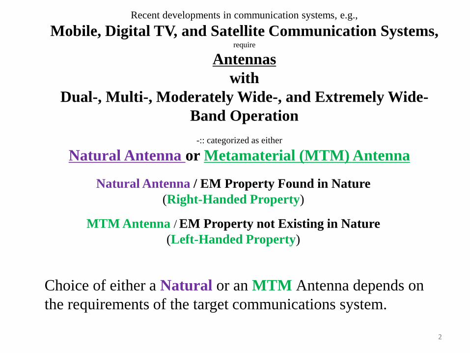
Recent developments in communication systems, e.g.,
Mobile, Digital TV, and Satellite Communication Systems, require
Antennas
with
Dual-, Multi-, Moderately Wide-, and Extremely Wide-
Band Operation
-:: categorized as either
Natural Antenna or Metamaterial (MTM) Antenna
Natural Antenna / EM Property Found in Nature
(Right-Handed Property)
MTM Antenna / EM Property not Existing in Nature
(Left-Handed Property)
Choice of either a Natural or an MTM Antenna depends on
the requirements of the target communications system.
2

TALK PRESENTATION
recent progress in some
Natural and MTM Antennas.
Low-Profile Structure
realizing
Moderately wideband characteristics
Wideband characteristics
Extremely wideband characteristics
Key Words ::
Low Profile Structure
Wideband Characteristics
3

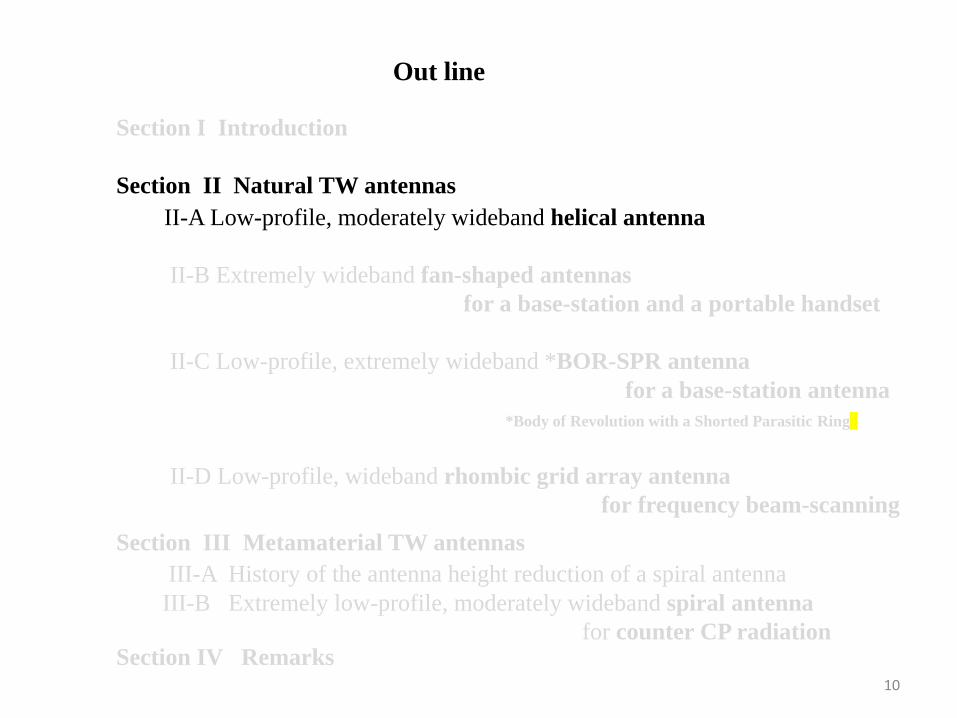
Section I Introduction
Section II Natural TW antennas
Out line
Section III Metamaterial TW antennas
Section IV Remarks
II-A Low-profile, moderately wideband helical antenna
II-B Extremely wideband fan-shaped antennas
for a base-station and a portable handset
II-C Low-profile, extremely wideband *BOR-SPR antenna
for a base-station antenna
*Body of Revolution with a Shorted Parasitic Ring
II-D Low-profile, wideband rhombic grid array antenna
for frequency beam-scanning
III-A History of the antenna height reduction of a spiral antenna
III-B Extremely low-profile, moderately wideband spiral antenna for counter CP radiation
4

Section I Introduction
Section II Natural TW antennas
Out line
Section III Metamaterial TW antennas
Section IV Remarks
II-A Low-profile, moderately wideband helical antenna
II-B Extremely wideband fan-shaped antennas
for a base-station and a portable handset
II-C Low-profile, extremely wideband *BOR-SPR antenna
for a base-station antenna
*Body of Revolution with a Shorted Parasitic Ring
II-D Low-profile, wideband rhombic grid array antenna
for frequency beam-scanning
III-A History of the antenna height reduction of a spiral antenna
III-B Extremely low-profile, moderately wideband spiral antenna for counter CP radiation
5

Practical Antenna Arms / / a Finite Length,
Current : composed of *
an out-going current & an in-coming current
The in-coming current
changes the situation at the antenna input.
~ changes the antenna input impedance in response to
the antenna shape & operating frequency.
in-coming current
out-going current
antenna input
(Current Distribution along Antenna Arms)*
6
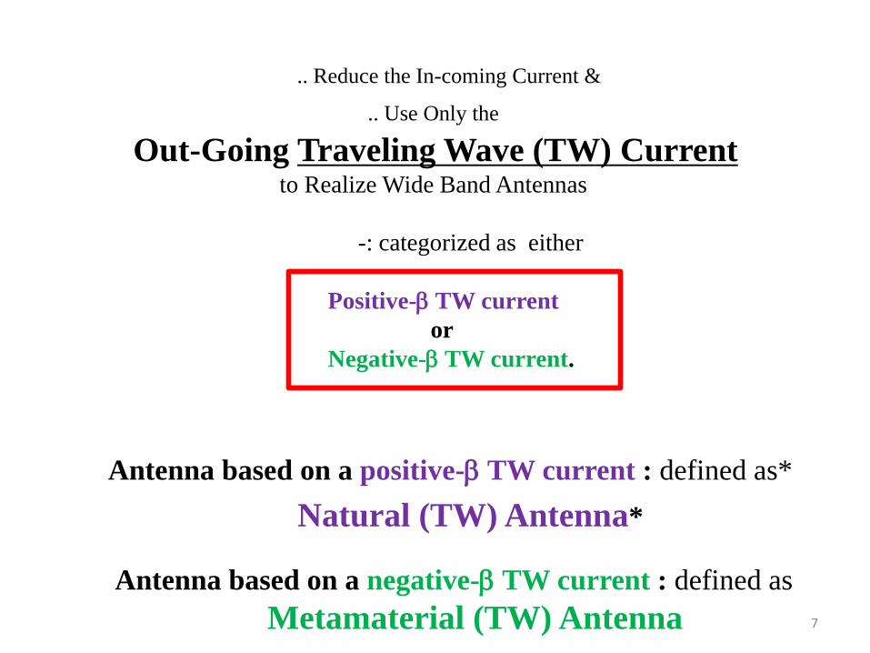
.. Reduce the In-coming Current &
.. Use Only the
Out-Going Traveling Wave (TW) Current to Realize Wide Band Antennas
-: categorized as either
Positive-b TW current
or
Negative-b TW current.
Antenna based on a positive-b TW current : defined as*
Antenna based on a negative-b TW current : defined as
Metamaterial (TW) Antenna
Natural (TW) Antenna*
7
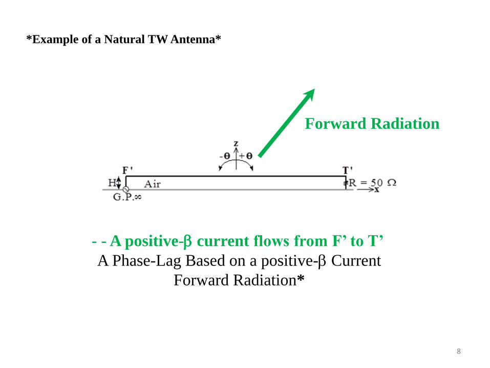
- - A positive-b current flows from F’ to T’
A Phase-Lag Based on a positive-b Current
Forward Radiation*
Forward Radiation
*Example of a Natural TW Antenna*
8

x
z
- - Capacitances and Inductances ::
inserted into a microstrip line*
*Example of a MTM TW Antenna
G.P.( )8
CL CL
LL
E
E
z
x0 -10 -20 [dB]
z
x0 -10 -20 [dB]
z
x0 -10 -20 [dB]
2.5 GHz 2.8 GHz 3.0 GHz
Backward Radiation
A negative-b current flows from the left to the right.
A Phase-Progress Based on a Negative-b Current
Backward Radiation
9
Section I Introduction
Section II Natural TW antennas
Out line
Section III Metamaterial TW antennas
Section IV Remarks
II-A Low-profile, moderately wideband helical antenna
II-B Extremely wideband fan-shaped antennas
for a base-station and a portable handset
II-C Low-profile, extremely wideband *BOR-SPR antenna
for a base-station antenna
*Body of Revolution with a Shorted Parasitic Ring
II-D Low-profile, wideband rhombic grid array antenna
for frequency beam-scanning
III-A History of the antenna height reduction of a spiral antenna
III-B Extremely low-profile, moderately wideband spiral antenna for counter CP radiation
10

FINDING
Current /
two distinct regions
C-current region* &
S-current region*
Helical Antenna
Feed Axial Mode
GP
11

Axial Mode Axial Mode
.. Remove the S-current region* &
.. use only the C-current region
for CP radiation
-/ a decaying TW current
along the helical arm of
~ two turns* *
2 turns
~ an antenna height of
0.19 wavelength
above the GP
Feed Axial Mode
GP
12
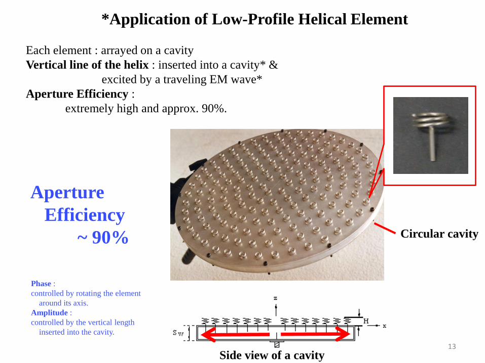
*Application of Low-Profile Helical Element
Each element : arrayed on a cavity
Vertical line of the helix : inserted into a cavity* &
excited by a traveling EM wave*
Aperture Efficiency :
extremely high and approx. 90%.
Side view of a cavity
Aperture
Efficiency
~ 90% Circular cavity
Phase :
controlled by rotating the element
around its axis.
Amplitude :
controlled by the vertical length
inserted into the cavity.
13

ARRAY /: used as
Indoor Broadcasting Satellite Receiving Antenna
Designed by Nakano Lab
Produced by Yagi Antenna Co.
Designed by Nakano Lab
Produced by TDK Co.
Dia. = 27.8 cm
G = 29.5 dBi,
/ Dia. = 33 cm
G = 31.7 dBi,
Aperture efficiency of h = 88%
Array applications
14
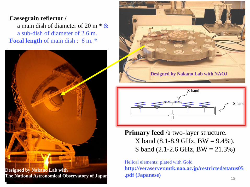
Primary feed /a two-layer structure.
X band (8.1-8.9 GHz, BW = 9.4%).
S band (2.1-2.6 GHz, BW = 21.3%)
Helical elements: plated with Gold
http://veraserver.mtk.nao.ac.jp/restricted/status05
.pdf (Japanese)
Cassegrain reflector /
a main dish of diameter of 20 m * &
a sub-dish of diameter of 2.6 m.
Focal length of main dish : 6 m. *
hu
X band
S band
Designed by Nakano Lab with
The National Astronomical Observatory of Japan
Designed by Nakano Lab with NAOJ
15
= 0oplane
0 -10 -20 (dB)90
o
x
60o 60
o
30o 30
o
0o
90o y
E
theoretical{z z
E
60o 60
o
30o 30
o
0o
= 90oplane
0 -10 -20 (dB)
f=12.45GHz
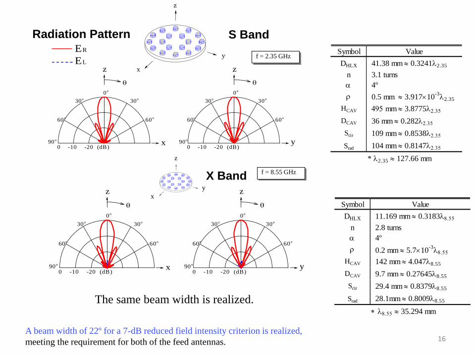
Radiation pattern
E sence and E sence
f = 2.35 GHz ER
EL
z
y
xx
z
y Symbol Value
DHLX 41.38 mm 0.3241l2.35
n 3.1 turns
a 4º
r 0.5 mm 3.91710-3
l2.35
HCAV 495 mm 3.8775l2.35
DCAV 36 mm 0.282l2.35
Scir 109 mm 0.8538l2.35
Srad 104 mm 0.8147l2.35
* l2.35 127.66 mm
A beam width of 22º for a 7-dB reduced field intensity criterion is realized,
meeting the requirement for both of the feed antennas.
S Band
= 0oplane
0 -10 -20 (dB)90
o
x
60o 60
o
30o 30
o
0o
90o y
E
theoretical{z z
E
60o 60
o
30o 30
o
0o
= 90oplane
0 -10 -20 (dB)
f=12.45GHz
Radiation pattern
E sence and E sence
f = 8.55 GHz
z
y
x
z
y
x
Symbol Value
DHLX 11.169 mm 0.3183l8.55
n 2.8 turns
a 4º
r 0.2 mm 5.710-3
l8.55
HCAV 142 mm 4.047l8.55
DCAV 9.7 mm 0.27645l8.55
Scir 29.4 mm 0.8379l8.55
Srad 28.1mm 0.8009l8.55
* l8.55 35.294 mm
X Band
The same beam width is realized.
Radiation Pattern
16

*Helical antenna array for a “BepiColombo”
Presented by
JAXA and
NEC-TOSHIBA Space System
17

Section I Introduction
Section II Natural TW antennas
Out line
Section III Metamaterial TW antennas
Section IV Remarks
II-A Low-profile, moderately wideband helical antenna
II-B Extremely wideband fan-shaped antennas
for a base-station and a portable handset
II-C Low-profile, extremely wideband *BOR-SPR antenna
for a base-station antenna
*Body of Revolution with a Shorted Parasitic Ring
II-D Low-profile, wideband rhombic grid array antenna
for frequency beam-scanning
III-A History of the antenna height reduction of a spiral antenna
III-B Extremely low-profile, moderately wideband spiral antenna for counter CP radiation
18

II. Natural Wideband antennas
II - B. CROSS-FAN and CROSS-FAN-S
8
8 8
8GP
- / Only an Out-going Current
IF: Conical Arm: Infinitely Long &
Ground Plane : of Infinite Extent
Input impedance : Frequency-Independent*
*Conducting Conical Antenna
Practical Structure
//The Conical Arm Cannot Be Infinitely Long!
19
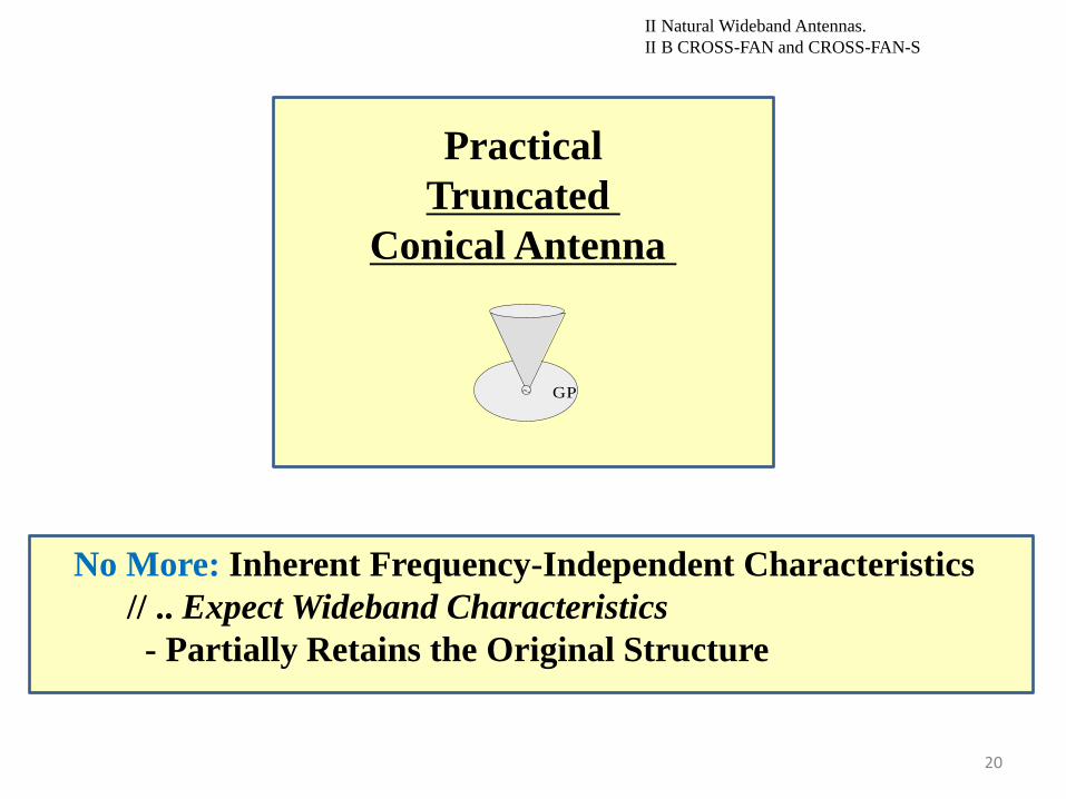
II Natural Wideband Antennas.
II B CROSS-FAN and CROSS-FAN-S
Practical
Truncated
Conical Antenna
GP
No More: Inherent Frequency-Independent Characteristics
// .. Expect Wideband Characteristics
- Partially Retains the Original Structure
20

~
x
y
z
.. FABRICATION
Low-Profile Antenna
- - A Pair of Fan-Shaped Plates
Intersect at Right Angles*
GP
Truncated
Conical Antenna*
Modification from a Truncated Conical to
A CROSS-FAN Antenna
II Natural Wideband Antennas.
II B CROSS-FAN and CROSS-FAN-S
21

Note: VSWR : less than two at frequencies above 2.1 GHz*.
Antenna Height : 0.3 Wavelength at 2.1 GHz.
Radiation : Omnidirectional around the antenna axis (z-axis).
frequency [GHz]
1 2 3 4 5 6 7 8 9 10 11
1
2
3
4
5
6
7
VS
WR
Figure 4
CROSS-FANCROSS-FAN
x
z
P(xP, 0, z
P)
Q(0, 0, zQ)
y
II Natural Wideband Antennas.
II B CROSS-FAN and CROSS-FAN-S
*Frequency Response of the VSWR of the Cross-Fan Antenna
Antenna Height : 0.3 Wavelength at 2.1 GHz
22
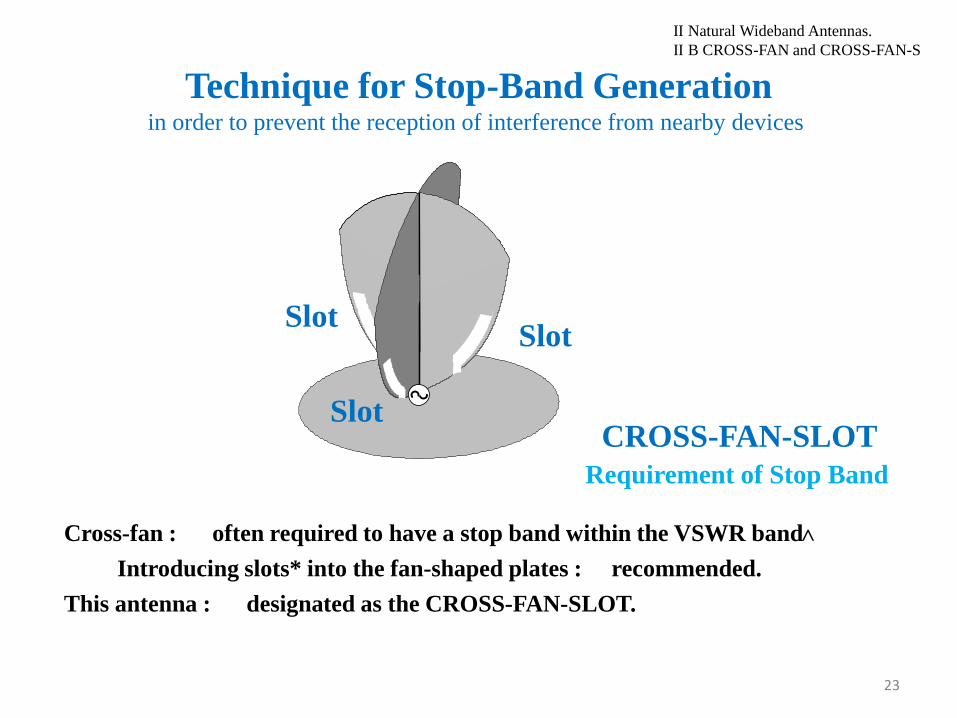
Cross-fan : often required to have a stop band within the VSWR band
Introducing slots* into the fan-shaped plates : recommended.
This antenna : designated as the CROSS-FAN-SLOT.
II Natural Wideband Antennas.
II B CROSS-FAN and CROSS-FAN-S
Technique for Stop-Band Generation in order to prevent the reception of interference from nearby devices
CROSS-FAN-SLOT
Slot Slot
Slot
Requirement of Stop Band
>
23

Slot Length Lslot : ~ one-quarter wavelength at fstop.
II Natural Wideband Antennas.
II B CROSS-FAN and CROSS-FAN-S *VSWR of the CROSS-FAN-SLOT
As Slot Length Lslot
Stop-Band Center Freq. fstop*
1 2 3 4 5 6 7 8 9 10 11
1
3
5
7
9
VS
WR
freque nc y [GHz ]
fs top
A Stop Band : * around 5.2 GHz
24

y
x
Ly
S
Q
ground plate
o
S
Lx
(a)Fan-shaped plate antenna CROSS-FAN /: Used as
a Base Station Antenna
.. MODIIFICATION CROSS-FAN for a Portable Handset
~
x
y
z
Base Station Antenna >>> Portable Handset Antenna
- REQUIREMENT Card-type Structure
.. REDUCTION Two fan-shaped plates to one plate ** &
.. MAKE Antenna Height Small - : Fan-shaped plate antenna
25

Ly
Lx
y
x
Ly
S
Q
ground plate
o
S
Lx
(a)
2ar
ro
Q
P1(x1,y1)
P2
P3
P0
S = 2r
r
FD
y
x
(b)
y
ground plate
2t
r z
(c)
* Detail of fan-shaped plate Antenna
Radiation Element & Ground plane lie in the same plane.
Radiation Element : sandwiched by dielectric substrates of r*.
Bandwidth : optimized by the inner angle 2a. *
Side Length S : ~1 cm. *
Ground Plane / a side length of 3 cm
r ~1 cm 3 cm
Radiation Element
GP
Side View
GP
26

*Frequency response of the VSWR
2a = 120 degrees.
(r, 2t, S) = (20, 1 mm, 10.87 mm),
(Lx, Ly) = (30 mm, 30 mm),
r = 5.44 mm
Note: VSWR < 2 above 2.75 GHz.
Antenna Height : 0.09l at 2.75 GHz.
Ground Plane / a side length of 3 cm
2ar
ro
Q
P1(x1,y1)
P2
P3
P0
S = 2r
r
FD
y
x
(b)
~1 cm
2 3 4 5 6 7 8 9 10 111
3
5
7
9
10
r = 20
2a = 120o
theo.
theo.
exp.{r = 1
VS
WR
frequency [GHz]
2a
( no dielectric layers
for the FASH)
27

- : Installed in a handset device. *
- : Sandwiched by dielectric substrates
Substrate /
an area of ~1 cm x 1 cm.
The substrate has an area of 1 cm by 1 cm.
The antennas installed inside a handset device.
Installation of a Fan-Shaped Antenna *
28
Designed by Nakano Lab.
Produced by Mitsumi Co.

Section I Introduction
Section II Natural TW antennas
Out line
Section III Metamaterial TW antennas
Section IV Remarks
II-A Low-profile, moderately wideband helical antenna
II-B Extremely wideband fan-shaped antennas
for a base-station and a portable handset
II-C Low-profile, extremely wideband *BOR-SPR antenna
for a base-station antenna
*Body of Revolution with a Shorted Parasitic Ring
II-D Low-profile, wideband rhombic grid array antenna
for frequency beam-scanning
III-A History of the antenna height reduction of a spiral antenna
III-B Extremely low-profile, moderately wideband spiral antenna for counter CP radiation
29
~
x
y
z
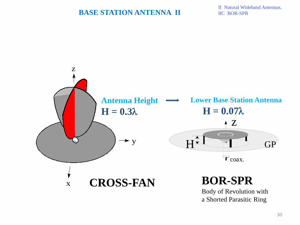
Antenna Height
H = 0.3l
CROSS-FAN
z
H c o a x .
GP
BOR-SPR Body of Revolution with
a Shorted Parasitic Ring
Lower Base Station Antenna
H = 0.07l
BASE STATION ANTENNA II II Natural Wideband Antennas.
IIC BOR-SPR
30

*BOR-SPR Antenna : composed of
a conducting body of revolution (feed section) *
& a parasitic conducting ring* :
shorted to the ground plane through conducting pins *.
Antenna Height : extremely small*: 0.07 wavelength.
II Natural Wideband Antennas.
II C BOR-SPR BOR-SPR Base-station Antenna
BOR
parasitic ring
conducting pin
H = 0.07l
z
H
c o a x .
GP
31
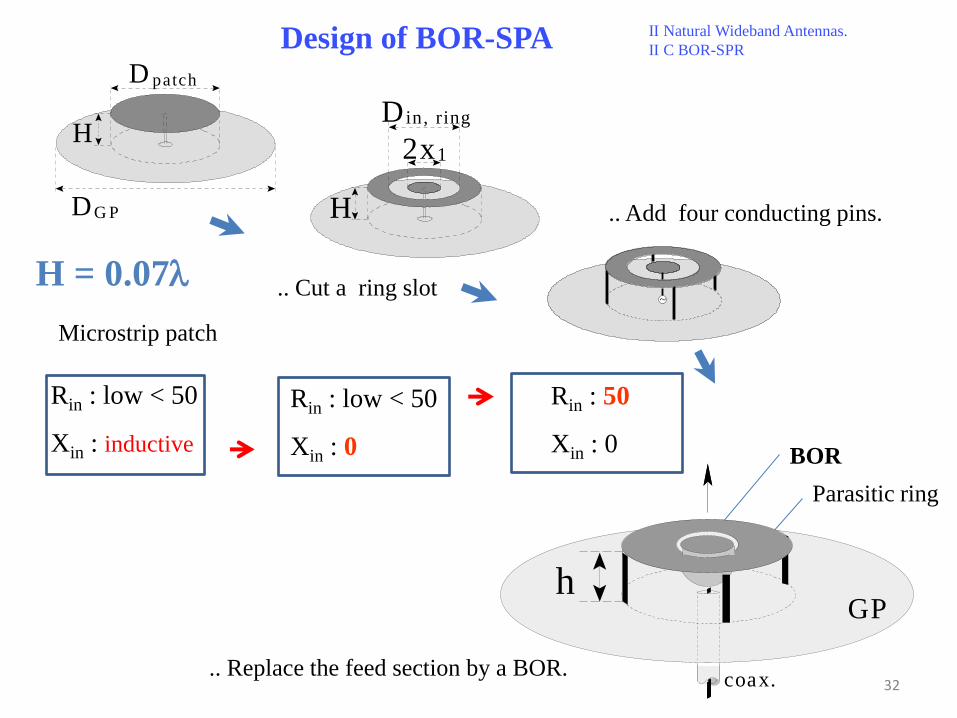
Design of BOR-SPA II Natural Wideband Antennas.
II C BOR-SPR
BOR
Parasitic ring
H
.. Replace the feed section by a BOR.
h
c o a x .
G P
.. Cut a ring slot
H
2 x 1
D i n , r i n g
Rin : low < 50
Xin : 0
H = 0.07l
Microstrip patch
H
D p a t c h
D G P
Rin : low < 50
Xin : inductive
~
.. Add four conducting pins.
Rin : 50
Xin : 0
32

First Step : to analyze the input impedance for a low-profile patch
Fig. 1(1/2)
H
Dpatch
DGP
Rin < 50 ohms
Xin : inductive
Note:
There is a frequency region where
the input reactance Xin is highly inductive.
2 . 5 3 . 0 3 . 5 4 . 0 4 . 5 5 . 0 - 1 0 0
0
1 0 0
2 0 0
3 0 0
4 0 0
f r e q u e n c y [ G H z ]
R i n
H = 1 0 m m
D p a t c h = 4 0 m m
D G P = 1 3 6 . 7 m m
X i n
Z i n
[ W
] GP dia. ~ 14 cm
Patch dia. ~ 4 cm
Antenna height H = 1 cm *
Design Process
33
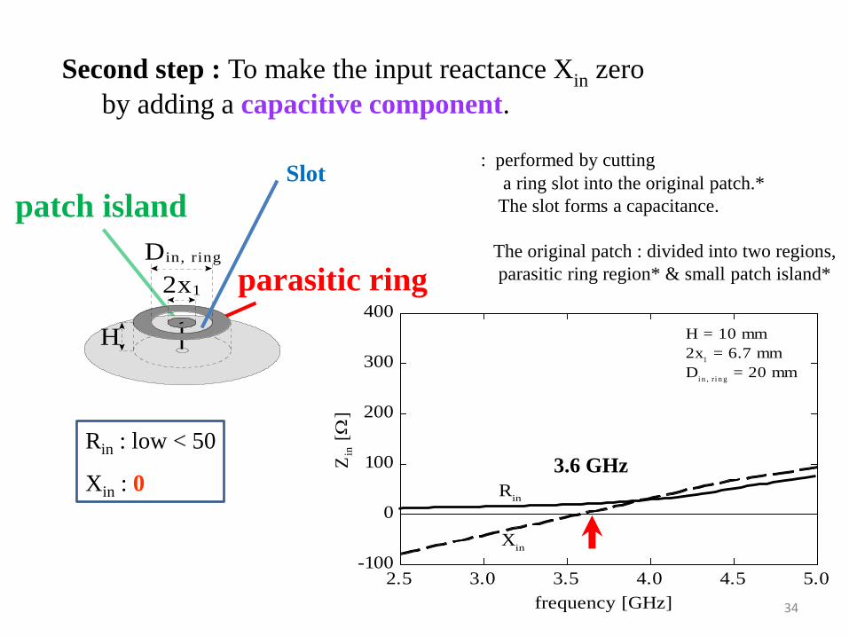
Second step : To make the input reactance Xin zero
by adding a capacitive component.
: performed by cutting
a ring slot into the original patch.*
The slot forms a capacitance.
The original patch : divided into two regions,
parasitic ring region* & small patch island*
Rin : low < 50
Xin : 0
patch island
parasitic ring
H
2x1
Din, ring
Slot
2.5 3.0 3.5 4.0 4.5 5.0-100
0
100
200
300
400
frequency [GHz]
Rin
H = 10 mm
2x1 = 6.7 mm
Di n , r i n g
= 20 mm
Xin
Zin [
W]
3.6 GHz
34

Third Step :To increase the input resistance Rin.
: achieved by increasing the antenna volume.
: performed by adding conducting pins & short them to the ground plane*.
2 4 6 8 1 0 1 2 1 4 1 6 1
2
3
4
5
6
7
f r e q u e n c y [ G H z ]
V S
W R
Rin : increased to 50 ohms
Xin : 0
~
conducting pin
30%
II Natural Wideband Antennas.
IIC BOR-SPR
35

Final Step : To further increase the frequency BW.
Antenna: excited by a central feed pin *
Central feed pin : replaced by a conducting body of revolution.*
Generating line of the BOR : defined by an exponential function.
H
Dpatch
DGP
H
2x1
Din, ring
~
Parasitic ring conducting pin H = 0.07l z
H
c o a x .
G P
BOR
30% BW
Excited by a Central Feed Pin
II Natural Wideband Antennas.
IIC BOR-SPR
36

* Frequency response of the VSWR for the BOR-SPR.
An extremely-wide frequency-band of
147% *
Note: The radiation :
omnidirectional around the z-axis.
1 3 5 7 9 11 13 151
2
3
4
5
6
7
frequency [GHz]
{
VS
WR
theo.exp.
Np i n
= 4
2x1 = 6.7 mm
H = 10 mm
z
H
c o a x .
GP
H = 0.07l
rpatch = 0.13l
147% BW
BOR-SPR
Body of Revolution with
Shorted Parasitic Ring 37

BOR-CROSS is installed on the ceiling of a building.
*Installation example
of BOR-CROSS*
Designed by Nakano Lab.
Produced by Yagi Antenna Co.
II Natural Wideband Antennas.
IIC BOR-SPR
38

Section I Introduction
Section II Natural TW antennas
Out line
Section III Metamaterial TW antennas
Section IV Remarks
II-A Low-profile, moderately wideband helical antenna
II-B Extremely wideband fan-shaped antennas
for a base-station and a portable handset
II-C Low-profile, extremely wideband *BOR-SPR antenna
for a base-station antenna
*Body of Revolution with a Shorted Parasitic Ring
II-D Low-profile, wideband rhombic grid array antenna
for frequency beam-scanning
III-A History of the antenna height reduction of a spiral antenna
III-B Extremely low-profile, moderately wideband spiral antenna for counter CP radiation
39

*Conventional Grid Array Antenna (GAA)
II Natural antennas
IID Rhombic grid array antenna
x
y
Ly
LxAir
G.P.
H
F T
z
GAA : excited from its edge*
- creates a tilted beam* *Beam direction*
/ a frequency-scanning function.
5 6 7 8 9-30
-15
0
15
30
45
60
Be
am
dir
ec
tio
n
(d
eg
)
Frequency (GHz)
*Beam Direction
as a function of frequency.
Feed Point F
Antenna height H = 2.5 mm
= 0.05l6
= 0.05l6
40

The gain should be constant
across the wide frequency band to be used for beam scanning.
Ga
in (
dB
i)
Frequency (GHz)
5 6 7 8 90
5
10
15
20
25
30
x
y
Ly
LxAir
G.P.
H
F T
z
?? Gain of the conventional GAA ??
?Desirable Gain Behavior?
41
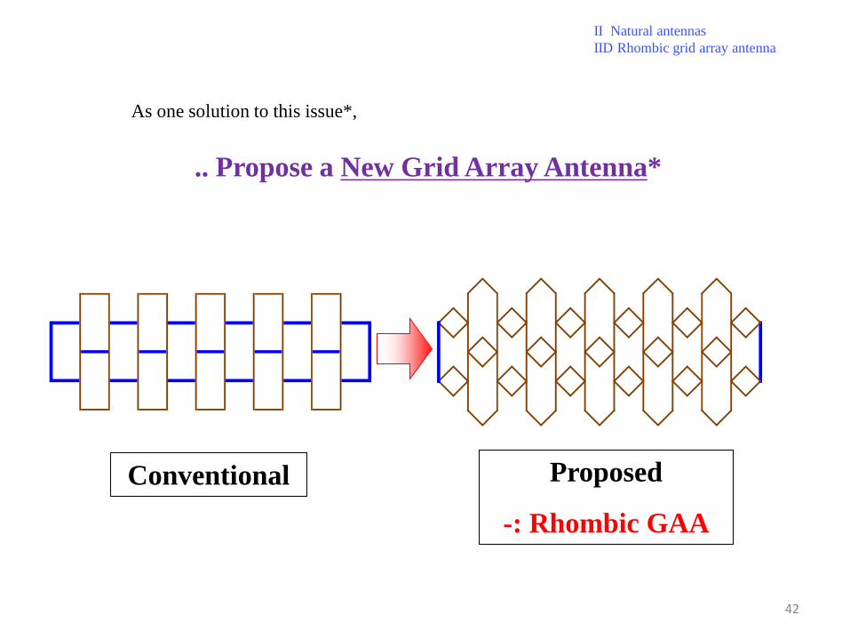
As one solution to this issue*,
.. Propose a New Grid Array Antenna*
Conventional Proposed
-: Rhombic GAA
II Natural antennas
IID Rhombic grid array antenna
42
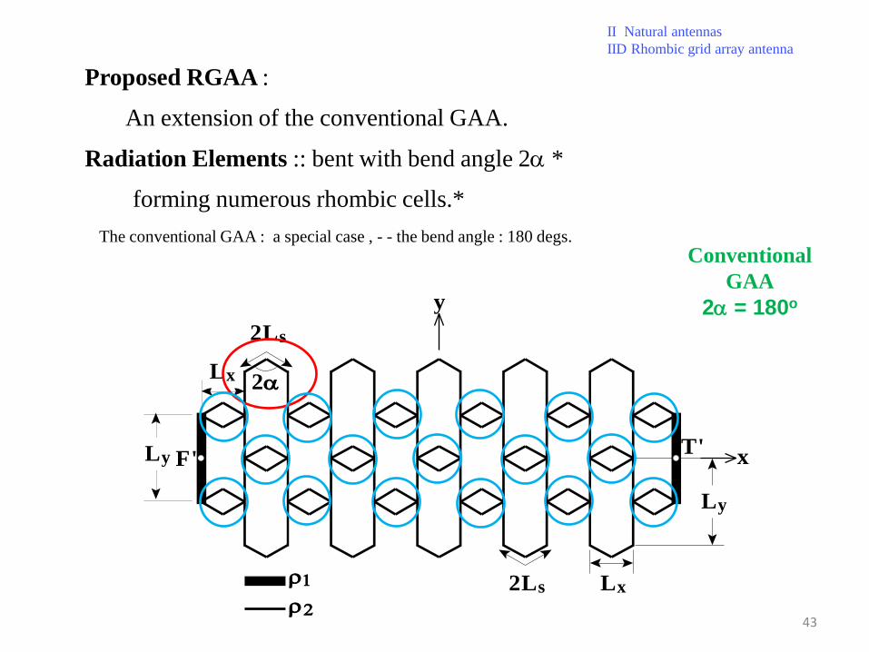
Proposed RGAA :
An extension of the conventional GAA.
Radiation Elements :: bent with bend angle 2a *
forming numerous rhombic cells.*
The conventional GAA : a special case , - - the bend angle : 180 degs.
II Natural antennas
IID Rhombic grid array antenna
x
y
Lx
Lx
Ly
Ly
2Ls
2Ls
2a
F'T'
r
r2
Conventional
GAA
2a = 180o
43

Note: -/ a constant gain across a wide frequency-band. *
the gain for the conventional GAA using a red dotted line*
: clear that the gain for beam scanning is improved.
*Gain for a RGAA -- bend angle of 2a = 120o.*
II Natural antennas
IID Rhombic grid array antenna
2a = 120o
Ga
in (
dB
i)
Frequency (GHz)
3-dB reduced gain
bandwidth
5 6 7 8 910
15
20
25
2a = 180o
Ga
in (
dB
i)
Frequency (GHz)
5 6 7 8 910
15
20
25x
y
Lx
Lx
Ly
Ly
2Ls
2Ls
2a
F'T'
r
r2
Constant Gain
across a wide frequency band
44
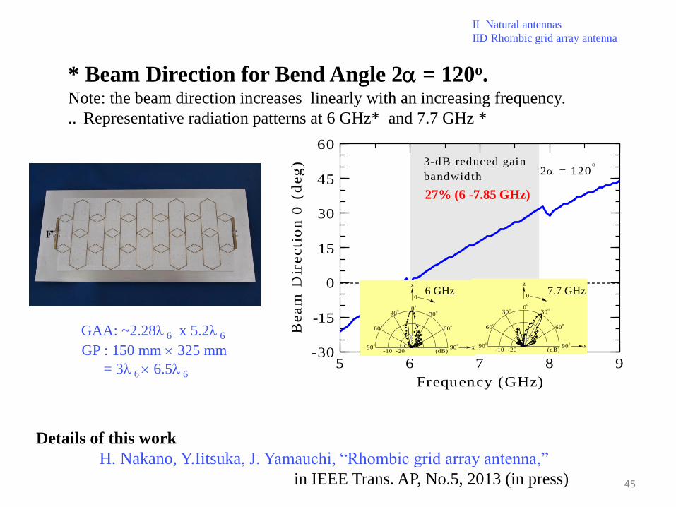
* Beam Direction for Bend Angle 2a = 120o. Note: the beam direction increases linearly with an increasing frequency.
.. Representative radiation patterns at 6 GHz* and 7.7 GHz *
2a = 120o
Be
am
Dir
ec
tio
n
(d
eg
)
Frequency (GHz)
3-dB reduced gain
bandwidth
5 6 7 8 9-30
-15
0
15
30
45
60
II Natural antennas
IID Rhombic grid array antenna
Details of this work
H. Nakano, Y.Iitsuka, J. Yamauchi, “Rhombic grid array antenna,”
in IEEE Trans. AP, No.5, 2013 (in press)
27% (6 -7.85 GHz)
0o
30o
60o
90o
90o
60o
30o
-10 -20 (dB)x
z
7.7 GHz
0o
30o
60o
90o
90o
60o
30o
-10 -20 (dB)x
z
6 GHz
45
F’
GAA: ~2.28l 6 x 5.2l 6
GP : 150 mm 325 mm
= 3l 6 6.5l 6

Section I Introduction
Section II Natural TW antennas
Out line
Section III Metamaterial TW antennas
Section IV Remarks
II-A Low-profile, moderately wideband helical antenna
II-B Extremely wideband fan-shaped antennas
for a base-station and a portable handset
II-C Low-profile, extremely wideband *BOR-SPR antenna
for a base-station antenna
*Body of Revolution with a Shorted Parasitic Ring
II-D Low-profile, wideband rhombic grid array antenna
for frequency beam-scanning
III-A History of the antenna height reduction of a spiral antenna
III-B Extremely low-profile, moderately wideband spiral antenna for counter CP radiation
46

~
Unidirectional CP wave
Bidirectional
Circularly polarized (CP) wave
Conducting plate
Frontward
Backward
~
Frontward
Spiral Antenna III MTM Antennas
IIIA History
47

x y
z
~
z
y
x
, t t F 1 F 2
r s
~ ~
h
z
y
L
F D
r s
~:: Two Techniques to overcome ::~
1st technique_ to place an absorbing ring-shaped strip*
Absorbing Ring-Shaped Strip behind the outermost arm area
Side view
Perspective view
Exploded view
First Technique
48
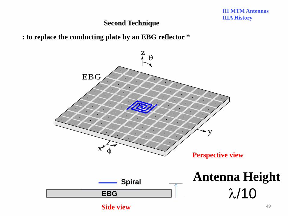
: to replace the conducting plate by an EBG reflector *
l/10
Antenna Height
Second Technique
EBG
z
y
x
EBG
Spiral
EBG
Side view
Perspective view
III MTM Antennas
IIIA History
49

Zin becomes constant when the conducting plate is replaced by an EBG reflector.
PEC SPA R i n
X i n
Frequency GHz
Z i n
[ W
]
5 . 4 6 . 0 6 . 6 7 . 2 7 . 8 - 4 0 0
- 2 0 0
0
2 0 0
4 0 0
6 0 0
PEC spiral (h = 0.1l6)
.. / Effect of an EBG-Reflector on Zin
EBG SPA
EBG spiral (h = 0.1l6)
EBG
z
y
x
III MTM Antennas
IIIA History
50

Q
Antenna Height
Is it possible to
further reduce the height of
a spiral antenna from l/10?
51

Section I Introduction
Section II Natural TW antennas
Out line
Section III Metamaterial TW antennas
Section IV Remarks
II-A Low-profile, moderately wideband helical antenna
II-B Extremely wideband fan-shaped antennas
for a base-station and a portable handset
II-C Low-profile, extremely wideband *BOR-SPR antenna
for a base-station antenna
*Body of Revolution with a Shorted Parasitic Ring
II-D Low-profile, wideband rhombic grid array antenna
for frequency beam-scanning
III-A History of the antenna height reduction of a spiral antenna
III-B Extremely low-profile, moderately wideband spiral antenna for counter CP radiation
52

spiral
l/4
~
conducting reflector
- - An antenna height of approximately l/100
.. CONSIDERATION
Further Antenna Height Reduction*
s p i r a l
A B S ~
c o n d u c t i n g r e f l e c t o r
l / 1 0
EBG Reflector l/10 ~ ~ l/100
x
y
l/100?
III MTM Antennas
IIIB Low-profile MTM Spirals
53

*Proposed Two-arm Spiral Antenna will be designed to meet two requirements.
- two feed points A and B *
- excited in balanced mode.
- Antenna arms: composed of numerous cells,
Cell * / two capacitors & one inductor.
Capacitors and inductor : : periodically added to the antenna arm.
G.P.( )8
CL CL
LL
.
1. Symmetrical Radiation Pattern
2. Extremely Low-profile Structure
F
(a) Perspective view.
x
y
o'A
B
SGPSsub
z
L M
LM- 1
54

Perspective view.
x
y
o'A
B
SGPSsub
z
L M
LM-1
1. Symmetrical Radiation Pattern
2. Extremely Low-profile Structure
B = 1.6 mm
~ 0.013 wavelength at 2.5 GHz
.. An Antenna Height of 1.6 mm*
III MTM Antennas
IIIB Low-profile MTM Spirals
55

b : phase constant along the arms
k0: phase constant in free space
fbalance : *balanced frequency : chosen to be 3 GHz
*Dispersion Diagram from 2 GHz to 5 GHz : Calculated Using Scattering Parameters [S]*
2 3 4 5-2
-1
0
1
2
b/k
0
Frequency [GHz]
fb ala nce
x
y
o'A
B
SGPSsub
z
L M
LM- 1
56

progressive regressive
fL : lower bound for a fast wave* fU : upper bound for a fast wave*
@ fL*, b/k0 = 1
@ fU*, b/k0 = 1
Dispersion Diagram
2 3 4 5 - 2
- 1
0
1
2
b / k
0
F r e q u e n c y [ G H z ]
f b a l a n c e f U f L
III MTM Antennas
IIIB Low-profile MTM Spirals
57

RH-CP Radiation LH-CP
// Dual-band Counter-CP Radiation//
If the antenna size is appropriately chosen
will appear will appear
2 3 4 5 - 2
- 1
0
1
2
b / k
0
F r e q u e n c y [ G H z ]
f b a l a n c e f U f L
III MTM Antennas
IIIB Low-profile MTM Spirals
58
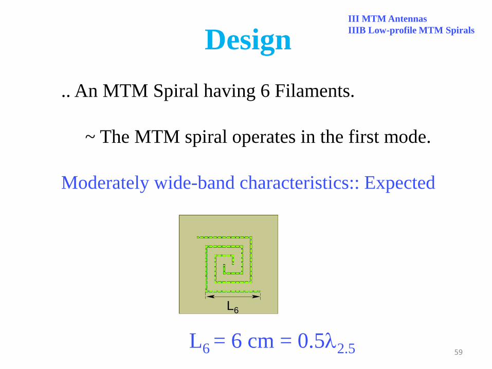
.. An MTM Spiral having 6 Filaments.
~ The MTM spiral operates in the first mode.
Moderately wide-band characteristics:: Expected
Design
III MTM Antennas
IIIB Low-profile MTM Spirals
59
L6
L6 = 6 cm = 0.5l2.5

* Frequency response of the gain
The maximum LH CP gain appears near the N-frequency.
The maximum RH CP gain appears near the H-frequency.
The gain has a moderately wideband characteristic
~ meets one of the requirement 2.
2.0 2.5 3.0 3.5 4.0 4.5 5.0-20
-15
-10
-5
0
5
10
15
20
Frequency[GHz]
GLfLH_ G
fL fbalan ce fU
fN fH
fR H_ G
GR
Ga
in(
= 0
,
= 0
)[d
Bi]
14.5%
14.0%
L6
Purposes
1. Symmetrical Radiation Pattern
2. Moderately Wideband Characteristics
M = 6
III MTM Antennas
IIIB Low-profile MTM Spirals
60
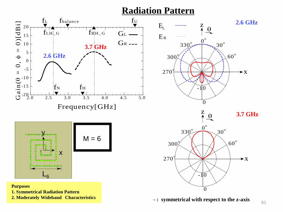
Radiation Pattern
2.6 GHz
0
-10
0o
30o
60o
270o
300o
330o
x
z
0
-10
0o
30o
60o
270o
300o
330o
x
z
- : symmetrical with respect to the z-axis
2.0 2.5 3.0 3.5 4.0 4.5 5.0-20
-15
-10
-5
0
5
10
15
20
Frequency[GHz]
GLfLH_ G
fL fbalan ce fU
fN fH
fR H_ G
GR
Ga
in(
= 0
,
= 0
)[d
Bi]
L6
x
y
3.7 GHz
Purposes
1. Symmetrical Radiation Pattern
2. Moderately Wideband Characteristics
2.6 GHz
3.7 GHz
M = 6
E R
E L
61

2.0 2.5 3.0 3.5 4.0 4.5 5.01
2
3
4
5
6
7
8
9
Frequency [GHz]
fL
fLH- G
GL BW GR BW
fRH-G
fUfbalan ce
fN fH
VS
WR
80
3 dB-reduction Gain Band Width
Frequency response of the VSWR for M = 6 *
The VSWR : less than 2 within the gain bandwidth 2.0 2.5 3.0 3.5 4.0 4.5 5.0
-20
-15
-10
-5
0
5
10
15
20
Frequency[GHz]
GLfLH_ G
fL fbalan ce fU
fN fH
fR H_ G
GR
Ga
in(
= 0
,
= 0
)[d
Bi]
2.6 GHz 3.7 GHz
M = 6
L6
x
y
III MTM Antennas
IIIB Low-profile MTM Spirals
62

Two-Arm MTM Spiral*
x
y
l/100
Dual-band Counter Circularly Polarized Radiation from a Single-arm Metamaterial-
based Spiral Antenna
in IEEE Trans AP, June, 2013 (accepted for publication)
Details of this work
A Monofilar MTM Spiral - does not require a balun circuit
- -
Effects of the pitch and ground plane
on the antenna characteristics :: *
x
ss u b(sG P)
ss u b(sG P)
LM
d
d
d
y
LM -1
B
F
Current Work
III MTM Antennas
IIIB Low-profile MTM Spirals
63

Section I Introduction
Section II Natural TW antennas
Out line
Section III Metamaterial TW antennas
Section IV Remarks
II-A Low-profile, moderately wideband helical antenna
II-B Extremely wideband fan-shaped antennas
for a base-station and a portable handset
II-C Low-profile, extremely wideband *BOR-SPR antenna
for a base-station antenna
*Body of Revolution with a Shorted Parasitic Ring
II-D Low-profile, wideband rhombic grid array antenna
for frequency beam-scanning
III-A History of the antenna height reduction of a spiral antenna
III-B Extremely low-profile, moderately wideband spiral antenna for counter CP radiation
64

An incoming current should be reduced
to realize a wideband antenna.
Some natural antennas, specified by a positive-b current,
realize wideband characteristics,
having a low profile structure.
The antenna height can be reduced
using a metamaterial property,
which is featured by a negative-b current.
REMARKS
Antenna Height from l/4 to l/100
65


![by William Chou...Figure 1.4: Blueprint for metamaterial antenna [8] 1.2 Metamaterial Antenna This thesis is motivated by the potential use of closely spaced metamaterial antennas](https://cdn.vdocument.in/doc/165x107/60933e3a3ab2c65ff317d896/by-william-chou-figure-14-blueprint-for-metamaterial-antenna-8-12-metamaterial.jpg)


