
NAVAL POSTGRADUATE
SCHOOL
MONTEREY, CALIFORNIA
MBA PROFESSIONAL REPORT
Development of a Rapidly Deployable Special Operations Component
Command (SOCC) Core Concept for the North Atlantic Treaty Organization (NATO) Special Operations Headquarters (NSHQ)
By: John Krott Frank Morales William Livingston
December 2011
Advisors: Dr. Keenan Yoho Col. Greg Wilson
Approved for public release; distribution is unlimited

THIS PAGE INTENTIONALLY LEFT BLANK

i
REPORT DOCUMENTATION PAGE Form Approved OMB No. 0704-0188Public reporting burden for this collection of information is estimated to average 1 hour per response, including the time for reviewing instruction, searching existing data sources, gathering and maintaining the data needed, and completing and reviewing the collection of information. Send comments regarding this burden estimate or any other aspect of this collection of information, including suggestions for reducing this burden, to Washington headquarters Services, Directorate for Information Operations and Reports, 1215 Jefferson Davis Highway, Suite 1204, Arlington, VA 22202-4302, and to the Office of Management and Budget, Paperwork Reduction Project (0704-0188) Washington DC 20503.
1. AGENCY USE ONLY (Leave blank)
2. REPORT DATE December 2011
3. REPORT TYPE AND DATES COVERED Master’s Thesis
4. TITLE AND SUBTITLE Development of a Rapidly Deployable Special Operations Component Command (SOCC) Core Concept for the North Atlantic Treaty Organization (NATO) Special Operations Headquarters (NSHQ)
5. FUNDING NUMBERS
6. AUTHOR(S) John Krott, Frank Morales, William Livingston
7. PERFORMING ORGANIZATION NAME(S) AND ADDRESS(ES) Naval Postgraduate School Monterey, CA 93943-5000
8. PERFORMING ORGANIZATION REPORT NUMBER
9. SPONSORING /MONITORING AGENCY NAME(S) AND ADDRESS(ES) N/A
10. SPONSORING/MONITORING AGENCY REPORT NUMBER
11. SUPPLEMENTARY NOTES The views expressed in this thesis are those of the author and do not reflect the official policy or position of the Department of Defense or the U.S. Government. IRB Protocol number ______NA__________.
12a. DISTRIBUTION / AVAILABILITY STATEMENT Approved for public release; distribution is unlimited
12b. DISTRIBUTION CODE A
13. ABSTRACT (maximum 200 words) The North Atlantic Treaty Organization (NATO) Special Operations Headquarters (NSHQ) is the primary point of development, direction, and coordination for all NATO Special Operations–related activities. NSHQ could enhance the effectiveness of NATO Special Operations Forces (SOF) and increase the probability of mission accomplishment when NATO SOF assets are collectively employed in a combined manner by adding an operational command and control capability. This would be in the form of a Special Operations Component Command (SOCC) “Core.” The SOCC Core is an advanced party of 70–150 personnel who provide an organic, rapidly deployable headquarters (HQ) capability for NSHQ. NSHQ does not currently have the ability to provide NATO with a rapidly deployable asset package, which would include a full suite of operational command, control, communication, computers, and intelligence (C4I) capabilities equipped with organic SOF and their enablers. The purpose of this thesis is to examine equipment and deployment configurations that will fulfill the mission requirements of the SOCC Core. An analysis of alternatives is conducted to determine which equipment types and configurations achieved the desired robust mission capability at the lowest possible cost. The focus is on the make-up of the four sub-components of the SOCC Core. These sub-components are the Operations Center (OPCEN), All-Source Center (ASC), Support Center (SUPCEN), and the Signals Center (SIGCEN). Possessing a rapidly deployable SOCC Core would be a sound step toward establishing and ensuring interoperability among allied SOF units and commands and would enhance the employment of NATO SOFs.
14. SUBJECT TERMS Development of a Rapidly Deployable Special Operations Component Command (SOCC) Core Concept for the North Atlantic Treaty Organization (NATO) Special Operations Headquarters (NSHQ)
15. NUMBER OF PAGES
149
16. PRICE CODE
17. SECURITY CLASSIFICATION OF REPORT
Unclassified
18. SECURITY CLASSIFICATION OF THIS PAGE
Unclassified
19. SECURITY CLASSIFICATION OF ABSTRACT
Unclassified
20. LIMITATION OF ABSTRACT
UU
NSN 7540-01-280-5500 Standard Form 298 (Rev. 2-89) Prescribed by ANSI Std. 239-18

ii
THIS PAGE INTENTIONALLY LEFT BLANK

iii
Approved for public release; distribution is unlimited
DEVELOPMENT OF A RAPIDLY DEPLOYABLE SPECIAL OPERATIONS COMPONENT COMMAND (SOCC) CORE CONCEPT FOR THE NORTH ATLANTIC TREATY ORGANIZATION (NATO) SPECIAL OPERATIONS
HEADQUARTERS (NSHQ)
John Krott Lieutenant Commander, United States Navy
B.A., University of Maryland at College Park, 1999
Frank Morales Lieutenant, United States Navy
B.S., Norfolk State University, 2004
William Livingston Lieutenant, United States Navy
B.S., Old Dominion University, 2007
Submitted in partial fulfillment of the requirements for the degree of
MASTER OF BUSINESS ADMINISTRATION
from the
NAVAL POSTGRADUATE SCHOOL
December 2011
Author: John Krott
Frank Morales
William Livingston
Approved by: Keenan Yoho
Thesis Advisor Gregory Wilson Thesis Co-Advisor William R. Gates Dean, Graduate School of Business and Public Policy

iv
THIS PAGE INTENTIONALLY LEFT BLANK

v
ABSTRACT
The North Atlantic Treaty Organization (NATO) Special Operations Headquarters
(NSHQ) is the primary point of development, direction, and coordination for all NATO
Special Operations–related activities. NSHQ could enhance the effectiveness of NATO
Special Operations Forces (SOF) and increase the probability of mission accomplishment
when NATO SOF assets are collectively employed in a combined manner by adding an
operational command and control capability. This would be in the form of a Special
Operations Component Command (SOCC) “Core.” The SOCC Core is an advanced
party of 70–150 personnel who provide an organic, rapidly deployable headquarters (HQ)
capability for NSHQ. NSHQ does not currently have the ability to provide NATO with a
rapidly deployable asset package, which would include a full suite of operational
command, control, communication, computers, and intelligence (C4I) capabilities
equipped with organic SOF and their enablers.
The purpose of this thesis is to examine equipment and deployment
configurations that will fulfill the mission requirements of the SOCC Core. An analysis
of alternatives is conducted to determine which equipment types and configurations
achieved the desired robust mission capability at the lowest possible cost. The focus is
on the make-up of the four sub-components of the SOCC Core. These sub-components
are the Operations Center (OPCEN), All-Source Center (ASC), Support Center
(SUPCEN), and the Signals Center (SIGCEN). Possessing a rapidly deployable SOCC
Core would be a sound step toward establishing and ensuring interoperability among
allied SOF units and commands and would enhance the employment of NATO SOFs.

vi
THIS PAGE INTENTIONALLY LEFT BLANK

vii
TABLE OF CONTENTS
I. INTRODUCTION........................................................................................................1A. ORIGIN OF THE NSHQ ................................................................................1B. RATIONALE AND IMPERATIVE FOR THE DEPLOYABLE HQ ........2C. THE MISSION AND VISION OF NATO SPECIAL OPERATIONS
HEADQUARTERS ..........................................................................................4D. LEADERSHIP AND STRUCTURE OF NSHQ ...........................................4
1. NATO and NSHQ Supporting Documents ........................................5E. STRATEGIC ENVIRONMENT IN WHICH NSHQ WILL
OPERATE ........................................................................................................9
II. BACKGROUND ........................................................................................................11A. THE FORMATION OF NATO SPECIAL OPERATIONS
HEADQUARTERS ........................................................................................11B. THE MAKE-UP OF NATO SPECIAL OPERATIONS
HEADQUARTERS ........................................................................................13
III. LITERATURE REVIEW .........................................................................................17
IV. THE PROBLEM TO BE SOLVED BY THE DEVELOPMENT OF A SOCC CORE ..........................................................................................................................23
V. THE MATERIAL SOLUTION FOR THE RAPIDILY DEPLOYABLE SOCC ..........................................................................................................................29A. SUPCEN (SUPPORT CENTER), COMPARISONS AND
CHARACTERISTICS SHELTERS: ALASKA STRUCTURES .............32B. HDT GLOBAL BASE-X AND AIR BEAM STRUCTURES ....................36C. AIR-SUPPORTED TEMPER HDT AIR BEAM STRUCTURE ..............43D. DRASH STRUCTURE SYSTEM ................................................................45E. WEATHERHAVEN STRUCTURES ..........................................................51F. HYGIENE SYSTEMS AND KITCHENS ...................................................54
1. Alaska Structures Ablutions .............................................................542. DRASH Mobile Hygiene System ......................................................553. Weatherhaven Support Facilities .....................................................56
G. MEDICAL FACILITIES ..............................................................................60H. OPTIONAL EQUIPMENT: BOBCAT .......................................................62I. OPCEN (OPERATIONS CENTER) COMMAND AND CONTROL
CENTER SHELTERS: ALASKA STRUCTURES COMMAND AND CONTROL .....................................................................................................64
J. HDT GLOBAL COMMAND AND CONTROL SYSTEM .......................65K. DRASH COMMAND AND CONTROL SYSTEM ....................................69L. THE WEATHERHAVEN COMMAND AND CONTROL SYSTEM .....72M. SPEC OPS, INC. (SOI) ..................................................................................75N. ALL-SOURCE CENTER (ASC): SOCC’S INTELLIGENCE
FUSION CELL...............................................................................................81
viii
1. SATCOM Bandwidth ........................................................................832. Data Storage .......................................................................................873. Processing Speed ................................................................................89
O. THE BATTLEFIELD INFORMATION COLLECTION AND EXPLOITATION SYSTEMS (BICES) .......................................................90
P. SIGNAL CENTER (SIGCEN)......................................................................93
VI. RECOMMENDATIONS .........................................................................................107A. COMMAND AND CONTROL CENTER DISPLAYS ............................118B. THE PHASE-IN APPROACH ...................................................................120
LIST OF REFERENCES ....................................................................................................123
INITIAL DISTRIBUTION LIST .......................................................................................129
ix
LIST OF FIGURES
Figure 1. NSHQ Contributing Nations (NSHQ Unpublished Brief, 2011) .......................2Figure 2. NSHQ Organizational Chart (NSHQ Unpublished Brief, 2011) .......................5Figure 3. NSCC Structure (NSHQ, 2006) .......................................................................12Figure 4. SOCC Diagram (Unpublished NSHQ Brief, 2011) .........................................15Figure 5. Alaska Gabled Structures .................................................................................33Figure 6. Transporting the AKSS (Alaska Structures) ....................................................34Figure 7. AKSS Shelters with Solar Fly (Alaska Structures) ..........................................36Figure 8. HDT Base-X® Model 307 Shelter Specifications (HDT Global) ...................37Figure 9. Model 307 Ready-Fold Floor (HDT Global) ...................................................38Figure 10. HDT Global Solar Shade Fly (HDT Global) ...................................................39Figure 11. HDT Balance of Systems (BOS) and Battery array (HDT Global) .................41Figure 12. Balance of System Characteristics (Global, HDT Balance of Systems,
2011) ................................................................................................................42Figure 13. HDT Alternate Energy Solution (HDT Global) ...............................................43Figure 14. HDT Air Beam Shelter System (HDT Global) ................................................44Figure 15. DRASH Structure System................................................................................45Figure 16. DRASH M-Series Specifications (DRASH) ...................................................47Figure 17. DRASH Series M Style Shelters (DRASH) ....................................................49Figure 18. DRASH UST Trailer (DRASH) ......................................................................50Figure 19. DRASH Durability Testing Results (DRASH, DRASH Brochure, 2011) ......51Figure 20. Weatherhaven Shelter (Weatherhaven) ...........................................................52Figure 21. Weatherhaven MECC and Soft-Sided Shelter (Weatherhaven) ......................53Figure 22. Alaska Structures Shower System (Alaska Structures) ...................................55Figure 23. DRASH Hygiene System (DRASH) ...............................................................56Figure 24. Weatherhaven Ablution System (Weatherhaven) ............................................57Figure 25. Tactical Re-deployable Expanding Container Capability (TRECC)
(Weatherhaven) ................................................................................................58Figure 26. Weatherhaven SHARC Fact Sheet (Weatherhaven SHARC Fact Sheet,
2011) ................................................................................................................59Figure 27. TRECC Being Loaded into the Back of a CH-47 (Weatherhaven) .................59Figure 28. Soft sided Medical Facilities (DRASH and Alaska Structures) ......................61Figure 29. Bobcat T770 Compact Track Loader (Bobcat, 2011) ......................................62Figure 30. Bobcat T770 Compact Truck Loader Specifications (Bobcat, 2011) ..............63Figure 31. Alaska Structures Large TOC (Alaska Structures) ..........................................64Figure 32. HDT Global Command and Control System (HDT Global) ...........................65Figure 33. HDT Digital Control Unit (DCU) (HDT Global) ............................................66Figure 34. HDT Interactive Video Display System (HDT Global) ..................................67Figure 35. HDT Global VDS Fact Sheet (HDT Global) ...................................................68Figure 36. HDT’s C2 Tables and Chairs ...........................................................................69Figure 37. DRASH Trailer Mounted Support System (TMSS) and Optional Shipping
Container (DRASH).........................................................................................70Figure 38. DRASH Command and Control Center(DRASH) ..........................................71

x
Figure 39. DRASH Large Command and Control Center (DRASH) ...............................72Figure 40. Weatherhaven MECC (Weatherhaven) ...........................................................73Figure 41. Weatherhaven TRECC (Weatherhaven) ..........................................................74Figure 42. Weatherhaven TRECC (Weatherhaven) ..........................................................75Figure 43. SOI’s Megawall Options (Spec Ops, Inc.) .......................................................76Figure 44. SOI’s Rapid Tactical Operation Center (RTOC) (Spec Ops, Inc.) ..................77Figure 45. SOI’s Rapid Tactical Operation Center (RTOC) (Spec Ops, Inc.) ..................78Figure 46. SOI’s Video Distribution Units (VDU), (Spec Ops, Inc.) ...............................79Figure 47. SOI Tactical Smart Tables ...............................................................................80Figure 48. SOI Standard Tactical Tables (Spec Ops, Inc.) ...............................................80Figure 49. All Source Center (ASC) (JP 2-0, Joint Intelligence, 2007) ............................81Figure 50. Intelligence Disciplines, Subcategories, and Sources (JP 2-0, Joint
Intelligence, 2007) ...........................................................................................82Figure 51. Estimated SATCOM Bandwidth Consumption. (Table built based on
information provided by NSHQ) .....................................................................84Figure 52. Typical Bandwidth Consumption Rates Spectrum. (Graph developed from
information gathered from multiple sources) ..................................................85Figure 53. The Biometric Analysis Tracking System, left (JP 2-0, Joint Intelligence,
2007) and Lighthouse Main Menu, right. (Image provided by Naval Post Graduate School Core Lab) .............................................................................89
Figure 54. Images from Palantir Intelligence Analysis Software (palantirtech.com/government/defense) ...........................................................90
Figure 55. BICES Network Diagram (Diagram provided by SOCOM) ...........................91Figure 56. NSHQ SOCC Concept for BICES (Diagram provided by NSHQ) .................92Figure 57. BICES Currently Being Used in Afghanistan (Diagram provided by
NSHQ) .............................................................................................................93Figure 58. Special Operations Forces Deployable Node Lite(vx) [SDN-L(vx)] (Image
provided by SOCOM) ......................................................................................94Figure 59. SDN-L(vx) Systems Capabilities Diagram (Image provided by SOCOM) .....95Figure 60. Special Operations Forces Deployable Node Medium (SDN-M) (Image
provided by SOCOM) ......................................................................................96Figure 61. SDN-M Systems Capabilities Diagram (Image provided by SOCOM) ..........97Figure 62. Special Operations Forces Deployable Node Heavy (SDN-H) (Image
provided by SOCOM) ......................................................................................98Figure 63. SDN-H Systems Capabilities Diagram (Image provided by SOCOM) ...........98Figure 64. Tactical Local Area Network (TACLAN) (Image provided by SOCOM) ....104Figure 65. Iridium Phones (Image from iridium.com) ....................................................105Figure 66. CH-47 Single Sling Load ...............................................................................111Figure 67. CH-47 Tandem Sling Load (Images, 2011) ...................................................112Figure 68. CH-47 Internal Load with TRECC (Weatherhaven) .....................................112Figure 69. Alaska Structures 150 Camp Drawing (Alaska Structure, personal
communication, November 11, 2011) ...........................................................116Figure 70. Major Decision Factors ..................................................................................117
xi
LIST OF TABLES
Table 1. NATO SOF Principal Tasks ..............................................................................7Table 2. Commercial Pricing for Windmill GBS. (www.windmill-intl.com) ..............87Table 3. Imagery File Size Spectrum(satimagingcorp.com) ..........................................87Table 4. SDN-Family Capabilities Chart (Information provided by SOCOM) ...........100Table 5. SDN-Family Major Pieces of Hardware Chart (Provided by SOCOM) ........101Table 6. SDN-Family Estimated Cost (Provided by SOCOM) ...................................103Table 7. Total Cost of SIGCEN ...................................................................................106Table 8. Manufacture Comparison...............................................................................108Table 9. Shipping and Cost Comparison Table ...........................................................115Table 10. Approximate Cost for NSHQ Camp ..............................................................121

xii
THIS PAGE INTENTIONALLY LEFT BLANK

xiii
LIST OF ACRONYMS AND ABBREVIATIONS
ACO Allied Command Operations ADVON Advanced Liaison AFS ACO Force Standards ACO Allied Command Operations ADVON Advanced Liaison AFS ACO Force Standards AKSS Alaska Small Shelter System ASC All Source Center BBM Baseband Module BICES Battlefield Information Collection and Exploitation System BICS Bobcat Interlock Control System BOS Balance of Systems C2 Command and Control C4I Command, Control, Communications, and Computers CIS Communication and Information Systems
CJFSOCC Combined Joint Force Special Operations Component Command
CMM Call Manager Module COCOM Combatant Command COTS Commercial Off-The-Shelf CS Combat Support CSS Combat Service Support DA Direct Action DJTF Deployable Joint Task Force DoD Department of Defense DSOO Directorate of Special Operations Office ECU Environmental Control Unit FOC Full Operational Capacity FOPS Falling Object Protective Structure HQ Headquarters HUMINT Human Intelligence IOC Initial Operating Capability IOC Initial Operational Capability IPL Imagery Product Library ISAF International Security Assistance Force ISR Intelligence, Surveillance, and Reconnaissance ITAR International Traffic in Arms Regulations JOA Joint Operations Area JRT Joint Response Team

xiv
JSOTF Joint Special Operations Task Force LEM Local Expansion Module MA Military Assistance MEF Marine Expeditionary Force MOU Memorandum of Understanding NA5CRO Non-Article 5 Crisis Response Operations NAC North Atlantic Council NATO North Atlantic Treaty Organization NAVSOC Navy Special Operations Command NAVSPECWARCOM
Naval Special Warfare Command
NCS NATO Command Structure NDF NATO Deployable Forces NFS NATO Force Structure NMA NATO Military Authorities NRF NATO Response Force NSCC NATO SOF Coordination Center
NSHQ North Atlantic Treaty Organization Special Operations Headquarters
NSTEP NATO SOF Training and Education Program NSTI NATO SOF Transformation Initiative NSWC Naval Special Warfare Center OPCEN Operations Center OPCOM Operational Command OPCON Operational Control PE Peacetime Establishment PIR Priority Intelligence Requirements RLS Real Life Support ROPS Roll Over Protective Structure SACEUR Supreme Allied Commander Europe SAPR Spring Applied, Pressure Released SCI Sensitive Compartmented Information SDN-H SOF Deployable Node Heavy SDN-L SOF Deployable Node Lite SDN-M SOF Deployable Node Medium SHAPE Supreme Headquarters Allied Powers Europe SHARC Specialized Helicopter and Aircraft Re-deployable Container SIGCEN Signals Center SJC Selectable Joystick Control SOCC Special Operations Component Command SOF Special Operations Forces SOF FN Special Operations Forces Fusion Node

xv
SOTG Special Operations Task Group SOTU Special Operations Task Unit SR Special Reconnaissance SUPCEN Support Center TACLAN Tactical Local Area Network TBM Tactical Ballistic Missile TMSS Trailer Mounted Support System TRECC Tactical Re-deployable Expanding Container Capability UPS Uninterruptible Power Supply USSOCOM United States Special Operations Command VGA Video Graphics Array WMD Weapons of Mass Destruction

xvi
ACKNOWLEDGMENTS
We would like to thank our spouses, Courtney Krott, Andrea Morales and Laura
Livingston, as well as our children, Kathryn, Mitchell, Ashley and Luke Krott; Gabby
Morales and Ronan, Liam and Seamus Livingston—for their tremendous love, support
and encouragement in our writing of this MBA Project. You all were as supportive as
possible as we were taken away from valuable family time to conduct research travel,
attend meetings or work on our project at the library. We cannot express enough
appreciation and thanks for their understanding as we dedicated ourselves to the research
involved with this project and asked them to make considerable sacrifices.
We would like to extend a sincere and emotional thank you to Dr. Keenan Yoho.
He is a brilliant leader, professor and mentor. His involvement in the project ensured its
success. Professors at the Naval Postgraduate School do not receive much credit for their
work in support of student theses; however, Dr. Yoho shared his unparalleled guidance,
expertise, advice, and knowledge with us. This is something we are humbled and
appreciative to have received. Most importantly he gave us his time. He spent countless
hours with us during meetings in support of this project. He also traveled with us on
numerous occasions in search of information for this project. His encouragement was
reminiscent of that you associate with the best sports coaches and military leaders. He
brought the best out of us (whether he believes this or not) and any one that has the
privilege of crossing paths with him.
Throughout the duration of this project, Dr. Yoho left a lasting impression on us.
This impression led us to believe he is made up of two parts: first, is his big mind which
makes him indispensable in an academic environment and explains his vast “renaissance
type” knowledge in a wide array of disciplines; and the second, the most important, is his
big heart. This is what makes him so special. He took in three wayward “lost” souls and
provided the guidance and mentorship they so desperately needed.

xvii
We would like to thank CAPT Barbara Ford for her support and assistance with
this project. The CAPT’s previous experience with NSHQ was of great benefit to the
thesis team. Whether it was a request to sign travel documents or ask for advice, she was
always willing to help us.
Additionally, we would like to thank the Acquisition Research Program,
especially RADM James Greene, USN (Ret), Ms. Karey Shaffer, and Ms. Tera Yoder,
for providing funding and resources to ensure the success of this MBA project. Ms.
Yoder worked tirelessly as an advocate on our behalf during this challenging and
demanding project. Without her assistance, understanding and compassion, we would
not have been able to complete this project.
We would also like to thank OF-4 Steven Basilici from NSHQ as a major
contributor to our project. Without his vision, the project would not have been possible.
His assistance helped us receive the required support and information from NSHQ
personnel. LTC Basilici was a great host during our initial visit to NSHQ and we are
grateful to have had the pleasure of working with him. We would like to thank
Lieutenant General Frank Kisner, Commander, NATO Special Operations Headquarters
for supporting the study. We would also like to thank OF-5 Stu Bradin, OF-5 Munoz,
OF-5 Bueschel, OF-5 Wildenberg, OF-5 Magne Rodahl, OF-5 IainWoodbridge, OF-5
Ferdinando Salvati, OF-5 Gregory Brinsfield, Mr. Ted Filler, Mr. Ken Murphy, Mr. Scott
Morrison, Mr. Pierre Deneu, Mr. Peter Carey and Mr. Vince Crepeau, Ms. Kerri Lewers,
Mr. Bob Holmes, Mr. Ronnie Rinaldi, Mr. Martin Spillman, OF-4 Mark Phillips, OF-4
Cory Peterson, OF-4 Travis Rooms, OF-4 Georg Fuchs, OF-4 Xavier Latournerie, OF-4
Irizzary, OF-4 Christer Liljedahl, OF-4 Andres Pintos, OF-4 David O’Brien, OF-4
Andrew Myers-Hemingway, OF-4 Olav Njos, OF-4 Dave Sherriff, OF-4 Manuel Vela,
OF-3 Robert Barron, OF-3 Gerald Murphy, OF-3 Tracy Burge, OF-3 Dewar Althea, OF-
3 Timothy Carlsson, OF-3 Claudio Dobocan, and OF-3 Gabe Szody.
xviii
We would like to thank SOCOM personnel, Mr Foley and other “unnamed
personnel” from San Diego who hosted member of our team this summer, for their time
in providing information and answers to our countless questions.
We would also like to thank a special communications officer, and “Do it all”
sergeant from Ft. Bragg, for hosting us for two days this summer; additionally, for
answering numerous follow -up e-mails with precise and impressive answers.
We would also like to thank personnel from the 1st MEF in Camp Pendleton
whom shared a fun filled and informative day with our team: Master Gunnery Sergeant
Trujillo, Gunnery Sergeant Jones, PO1 Hartt, PO1 Lopez, and Mr. James Walters.
We would also like to thank CPT Alan Nydegger and CPT Ben Bowman from
CPT Ben Bowman from the Stockton Army Aviation Support Facility (AASF). CPT
Bowman hosted us for a day and answered numerous questions. He showed us around
the Chinook aircraft and their maintenance facility.
Finally, we would like to thank the SOF Chair of the Defense Analysis
Department, COL Greg Wilson, USA, for his role as a support advisor.

1
I. INTRODUCTION
This project was conducted at the request of the North Atlantic Treaty
Organization (NATO) Special Operations Headquarters (NSHQ) to develop materiel
options that would contribute to the creation of a rapidly deployable headquarter (HQ).
The focus of this study is on the four “CENs” [Logistics Center (LOGCEN), Support
Center (SUPCEN), Operations Center (OPCEN), All-Source Center (ASC), and Signal
Center (SIGCEN)].
NSHQ desired to have the rapidly deployable HQ solution come within $12M.
This study investigates options for all four “CENs” and makes recommendations to the
leadership of NSHQ based upon requirement, capability, value, and durability. Leading
up to our recommendations, we will discuss the origin of NSHQ and how it has evolved
into an operational command. This will help the reader understand the rationale and
imperative for the desired rapidly deployable HQ. Additionally, we will provide the
background of NSHQ’s formation, structure, and doctrine to gain a better understanding
of how NSHQ operates.
We also will review what has been written about developing a rapidly deployable
HQ before laying out the problem that NSHQ is seeking to solve. The core of this project
revolves around the four “CENs”; moreover, the requirements, the capabilities available,
and the best equipment for each “CEN” to fulfill the mission. At the conclusion of this
project, we have made recommendations based on extensive research to effectively
develop a rapidly deployable HQ.
A. ORIGIN OF THE NSHQ
The NSHQ is a concept that emerged from the NATO Special Operations Forces
(SOF) Transformation Initiative (NSTI) approved by the North Atlantic Council (NAC)
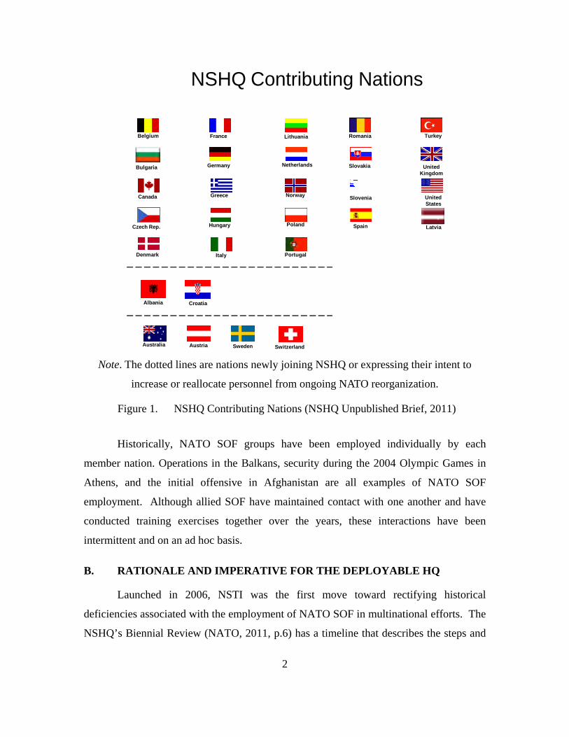
on November 22, 2006. There are currently 28 NATO member nations, and 26 of those
possess SOF. The NSHQ initiative was intended to effectively orchestrate collective
SOF employment by NATO member nations. Figure 1 displays the national flags and
country names of all the nations that contribute to NSHQ.
2
Belgium
Greece Norway
UnitedKingdom
Canada
Hungary Poland SpainCzech Rep.
Italy Portugal
UnitedStates
France Lithuania Romania
Germany Netherlands Slovakia
Slovenia
Turkey
Denmark
Bulgaria
Latvia
UnitedStates
NSHQ Contributing Nations
Australia Austria Sweden
Albania Croatia
Switzerland
Note. The dotted lines are nations newly joining NSHQ or expressing their intent to
increase or reallocate personnel from ongoing NATO reorganization.
Figure 1. NSHQ Contributing Nations (NSHQ Unpublished Brief, 2011)
Historically, NATO SOF groups have been employed individually by each
member nation. Operations in the Balkans, security during the 2004 Olympic Games in
Athens, and the initial offensive in Afghanistan are all examples of NATO SOF
employment. Although allied SOF have maintained contact with one another and have
conducted training exercises together over the years, these interactions have been
intermittent and on an ad hoc basis.
B. RATIONALE AND IMPERATIVE FOR THE DEPLOYABLE HQ
Launched in 2006, NSTI was the first move toward rectifying historical
deficiencies associated with the employment of NATO SOF in multinational efforts. The
NSHQ’s Biennial Review (NATO, 2011, p.6) has a timeline that describes the steps and

3
stages that culminated with the formation of NSHQ. NATO held the Riga Summit on
November 28–29, 2006. Attendees of this summit focused on the transformation of
NATO. An article on the Riga Summit’s webpage (http://www.rigasummit.lv/en/)
quoted President Bush as stating that NATO was in transition from a static force to an
expeditionary force and that NATO’s Special Operation Forces initiative was one of the
key things on the table at the summit. At the Riga Summit, heads of state and
governments endorsed NSTI (NSHQ, 2010d, p. 6).
Today, SOF fill a far more significant role than they did in the environment for
which the original NATO military structure was designed. NATO’s current SOF staff
structure, despite having made important contributions, is inadequately located,
resourced, and connected in order to accomplish the necessary strategic groundwork that
today’s environment demands. The challenge today is to coordinate strategic SOF
solutions based on standardized and validated capabilities.
A solution to the challenge mentioned above was addressed by NATO, with three
recommendations:
1. Reposition the Directorate of Special Operations Office (DSOO) on the
special staff of the Supreme Allied Commander Europe (SACEUR). The
intention of NATO was to position SOF to deliver special operations-
related advice and assistance directly into the strategic level at the Allied
Command Operations (ACO).
2. Create the NATO SOF Coordination Centre (NSCC). The North Atlantic
Council (NAC) on September 25, 2009, later directed the NSCC to
reorganize into NSHQ.
3. Develop a NATO SOF Training and Education Program (NSTEP). This
effort is focused on NATO SOF-specific training and education intended
to enhance commonality in doctrine, procedures, and (in some cases)
equipment among allied SOF. (NSHQ, 2010)

4
C. THE MISSION AND VISION OF NATO SPECIAL OPERATIONS HEADQUARTERS
The mission of NSHQ is to serve as “the primary point of development, direction
and coordination for all NATO Special Operations related activities to optimize the
employment of SOF, to include providing an operational command capability when
directed by the Supreme Allied Commander Europe (SACEUR)” (NSHQ, 2009a). The
objective is for NSHQ to enhance the probability of collaborative success when allied
SOF assets operate in a combined manner. Adding an “operational command capability”
in the mission includes an operational command and control role through provision of the
“core” for an organic, rapidly deployable SOCC when directed by the SACEUR.
According to its NATO International Military Body status, NSHQ can be tasked
to support different elements of NATO and other national entities by deploying tailored
planning and liaison teams. The vision of NSHQ is to be the alliance SOF proponent for
NATO SOF policy, standards, doctrine, training, education, and assessments. In this
position, NSHQ maintains and develops a robust operational command, control,
communications, computers, and intelligence (C4I) capability, equipped with organic
SOF enablers to ensure interoperability and to enhance employment of NATO Special
Operations (NSHQ, 2010).
D. LEADERSHIP AND STRUCTURE OF NSHQ
As a member of SACEUR special staff, the NSHQ director provides advice on
Special Operations. In this essential function, NSHQ enables and supports NATO SOF
throughout the alliance and provides the focal point for NATO Special Operations
expertise to SACEUR and ACO. (NSHQ, 2010c)
NSHQ is a NATO organization that receives personnel from NATO member
nations through a memorandum of understanding (MOU). Member nations apply for and
offer personnel based on the size and maturity of their SOF. An NSHQ SOC CORE
Concept Brief (NSHQ unpublished brief, 2010g) detailed the current manning, which
indicated it is at its initial operating capability (IOC) of 149 positions. NATO’s goal is to
have growth in three phases. Phase one is the IOC. Phase two includes a deployable

5
headquarters element of approximately 70 personnel, a slated personnel level of 188, and
a 2012 implementation date. Phase three includes multiple deployable headquarters
elements, a desired personnel level of 214, and a 2013 implementation date.
Figure 2 is a diagram of the current NSHQ command structure. This flat
organization not only emphasizes, but also requires, decentralized decision-making of
subordinate departments under a centralized command and control element. This
structure will be duplicated with the deployable headquarters element NSHQ and will
supply to future contingency operations.
Figure 2. NSHQ Organizational Chart (NSHQ Unpublished Brief, 2011)
1. NATO and NSHQ Supporting Documents
In the document Final Decision on MC 324/2, The NATO Military Command
Structure (NATO, 2010b), NATO lists critical success factors for the alliance. One of
the most important to our study is how NATO military operations rely on communication
and information system infrastructure for effective command and control (C2; NATO,

6
2010b). NATO alliance nations must be committed to resource the headquarters (HQs),
and host nations with available capacity must assist NATO while it is operating in their
territory.
NSHQ is a new and evolving organization, which was instructed to develop a
rapidly deployable HQ. NSHQ receives its authority from the document Draft MC Policy
for Allied Forces and Their Use for Operations (NATO, 2011). In this document, NATO
Military Authorities (NMA) agreed to the NATO Deployable Forces (NDF) concepts.
In the Background section of the Draft MC Policy (NATO, 2011), NATO states,
This policy is a single overarching concept, eliminating redundancy, and integrates new deployable operational C2 structures (notably NSHQ) agreed through the Peacetime Establishment (PE) Review of the NATO Military Command Structure [NCS]. NCS provides NATO with the capability to conduct both Article 5 and Non-Article 5 Crisis Response Operations (NA5CRO). (p. 3)
Later in the document, NATO addresses the key elements necessary for a force to
be considered deployable. It states, “For a HQ or a unit to be ‘declared ready’, it is to be
manned, trained and equipped to the necessary predefined and agreed standards, laid
down by SACEUR, which will be identified in the ACO Force Standards (AFS)”
(NATO, 2011).
In this document, NATO also addresses SOF, specifically with a paragraph in the
NATO Force Structure (NFS) section that breaks down SOF elements:
SOF offer specific capabilities which are heavily reliant upon a wide range of enablers. Nations are expected to provide SOF with their full suite of organic enablers and Combat Support and Combat Service Support units. A Special Operations Component Command (SOCC) must in principle be generated for every operation involving the employment of SOF. A SOCC is formed around NSHQ or a SOF framework nation and is structured for each operation according to the number of Special Operations Task Groups (SOTGs) assigned and the degree of C2 required. (NATO, 2011)
The SOF policy with which NSHQ must operate is dictated in the 3rd Draft MC
0437/2 Special Operations Policy (NATO, 2010a). This document includes a list of the
items differentiating SOF from conventional forces:

7
Politico-military considerations may require discreet or covert techniques and the acceptance of a degree of political, military, or physical risk not associated with conventional operations. SOF are strategic assets to be employed to help achieve strategic and specified operational-level objectives. They differ from other joint forces principally through their unique capabilities, agility, and flexibility. SOF are commanded through a SOCC usually under an operational-level HQ alongside land, air, or maritime forces. In a burgeoning crisis SOF may establish an early forward presence in order to initiate military and civilian liaisons, conduct area assessments, provide an early command and control capability, or advise friendly forces. SOF provide NATO with increased understanding of a developing crisis and, if required, help set the conditions for the initial entry of joint forces. (p. 3)
The draft policy also lists the three principal tasks of NATO SOF (Table 1):
military assistance (MA), special reconnaissance (SR), and direct action (DA).
Table 1. NATO SOF Principal Tasks
MA is a broad range of activities that support and influence critical friendly assets through training, advising, mentoring, or the conduct of combined operations. The range of MA is thus considerable, and includes, but is not limited to, capability building of friendly security forces; engagement with local, regional, and national leadership or organizations; and civic actions supporting and influencing the local population. (NATO, 2010a)
Military assistance is important in building lasting relationships that benefit all
involved nations in ways that cannot be quantified, as these relationships will enable
NSHQ to operate more effectively through an enhanced collaborative network (NATO,
2010a).
The next NATO SOF and in turn NSHQ principal task is SR.
SR is an activity conducted by SOF to support the collection of a commander’s Priority Intelligence Requirements (PIR) by employing unique capabilities. These activities may vary widely, from traditional ‘eyes on target’ surveillance in high risk environments to other actions that
Military Assistance (MA) Surveillance & Reconnaissaince (SR) Direct Action (DA)
Working by with and through Personnel on the ground Fast, Violent, Assault
Host Nation forces; provide clandestinely providing Operation with follow
advising, training and "Eyes On" Intelligence. on exploitation of target.
mentorship.

8
may include, but are not limited to: human intelligence (HUMINT) collection, close target reconnaissance, or the employment of Intelligence, Surveillance, and Reconnaissance (ISR) assets.” (NATO, 2010a)
Surveillance and reconnaissance are two key methods to be used by the SOCC
Core commander to gain essential intelligence generated from his own personnel on the
ground. It is risky, because a compromise in the field could put future missions at risk
and provide a warning to those being watched (NATO, 2010a).
DA is the third of the three principal tasks to be conducted by NSHQ. A
definition of DA taken from the NATO SOF Policy document:
DA is a precise offensive operation conducted by SOF which is limited in scope and duration in order to seize, destroy, disrupt, capture, exploit, recover, or damage high value or high payoff targets. DA differs from conventional offensive actions in the level of risk, techniques employed, and the degree of precision utilized to achieve a specific effect. (NATO, 2010a)
Direct action missions are violent, aggressive, and surgical strikes conducted at
great risk to the operators. Successful operations have the ability to yield an abundance
of intelligence and generate strategic effects.
The SOCC has operational control (OPCON) of each individual nation’s SOF
Special Operations Task Group (SOTG). Individual alliance nations never relinquish full
command of their forces. Because there is no standing SOCC, an SOCC must be
generated for each operation in which the SACEUR and the NATO Security Council
approves NATO involvement. NATO (2010a) defines an SOCC as “a multi-national or
national command formed around a SOF Framework Nation and … structured for each
operation according to the number of SOTGs assigned and the degree of C2 required”
(p. 4). With the SOCC defined, the unit will not be considered deployable until it
achieves full operational capacity. According to NATO (2010a), “At full operational
capacity, NSHQ can provide a rapidly deployable initial core of an operational SOCC.
This capability does not replace the requirement of a SOF Framework Nation but does
serve as a requisite enhancement to SOF force generation” (p. 5).

9
There are two key responsibilities of NSHQ. The first responsibility is to “provide
NATO SOF expertise and enablers while retaining an organic command, control,
communications, computers and intelligence (C4I) capability in the support and
employment of SOF in NATO operations” (NATO, 2010a.) The other key responsibility
of NSHQ is to provide an initial core of an operational SOCC upon the direction of the
SACEUR (NATO, 2010a). The key responsibility of NATO SOF contributing nations is
to supply the full suite of enablers, combat support (CS), and combat service support
(CSS) elements their SOF troops rely on. When an SOF troop is provided to NATO, and
subsequently to an SOCC in a joint operations area (JOA), it must be fully enabled
organically (NATO, 2010a).
E. STRATEGIC ENVIRONMENT IN WHICH NSHQ WILL OPERATE
The strategic environment in which NSHQ operates is a constantly changing and
evolving environment. There are known flashpoints and areas of unrest throughout the
world. NATO and NSHQ are in a constant cycle of gathering intelligence and making
operational preparations in an effort to impact these areas for the greater good of mankind
(and, in turn, NATO alliance nations). NSHQ’s flexibility, agility, capability, training,
and skills give it an advantage in responding to situations for which there could be no
prior preparation. Through an exhaustive, thorough, and detailed intelligence analysis,
NATO attempts to be preemptive in its analysis of all the things that could possibly
happen. A part of its analysis is identifying indicators. Once these indicators are
identified, it is up to NATO and its vast intelligence network to monitor them (NATO,
2010a).
Key worldwide indicators are addressed and analyzed in the classified NATO
secret document NATO Strategic Intelligence Estimate: Final Decision on MC
0161/NSIE/10 (NSHQ, 2010d). The document breaks down identifying indicators into
three sections: transnational trends and emerging technologies (terrorism, cyber-threats,
etc.), geopolitical environment (regional trouble spots that may include Sub-Saharan
Africa, etc.), and transnational assessments. Transnational assessments may include the
proliferation of weapons of mass destruction (WMD), and environmental and resource
10
issues of special interest. Geopolitical assessments are then conducted on each
worldwide region with indicators of potential crisis (NSHQ, 2010a).
The purpose of Chapter I was to illustrate how quick NSHQ has evolved.
NSHQ’s roots began with few motivated individuals acting as a liaison between the
different nations’ SOF commands. NSHQ has come a long way in a short amount of
time. Adding operation command capability and developing a C4I infrastructure is the
next milestone for NSHQ. This achievement will further increase their success while
operating in a complex environment. Chapter II will discuss, in greater detail, the
background of NSHQ’s evolution.

11
II. BACKGROUND
In Chapter I, we provided an introduction to NATO Special Operations; in this
chapter, we provide some background into the formation of NSHQ. In 1980, a failed
mission to rescue U.S. hostages held by terrorists in Iran (Operation Eagle Claw)
displayed how ineffective U.S. Special Forces were when they used ad hoc command and
control with units brought together quickly to execute high-profile, high-risk missions.
These units did not have a habitual relationship in a training or real-world environment.
In 1987, the U.S. military rectified this shortfall by forming the United States Special
Operations Command (USSOCOM).
NATO did not require an operational failure on the world stage to goad them into
addressing the need to change the manner in which their SOF were employed. From
1991 to 2006, Norway, the United Kingdom, France, Germany, the Netherlands, Canada,
and Italy followed suit by forming national SOF organizations (NSCC, 2008). On
November 29, 2006, at the NATO Riga Summit, the heads of state and government
officials of NATO member nations approved the NATO SOF Transformation Initiative
(NSTI).
A. THE FORMATION OF NATO SPECIAL OPERATIONS HEADQUARTERS
In September 2006, the North Atlantic Military Committee (NSHQ, 2006)
published NSTI Advice, a document in which the committee recommended three elements
as the foundation for NATO SOF’s transformation. The first element was enhancing
staff capacity at Supreme Headquarters Allied Powers Europe (SHAPE) by creating the
SHAPE Special Operations Office (SSOO); the second element was establishing a
NATO SOF Coordination Center (NSCC); and the third element was developing a
NATO Federation of SOF Training Centers.
With these three elements, NATO SOF went from a fusion center to a
coordination center. The role of the SSOO was to provide the SACEUR with resident
strategic-level Special Operations advice in order to direct and enable the employment of

12
alliance SOF (NSHQ, 2006). The SACEUR made requests for NATO SOF through the
SSOO, which passed these requests to the NSCC. The role of the NSCC was to provide
the SACEUR with Special Operations expertise for strategic and operational planning to
include the conduct of operations. The director of the NSCC was responsible for
providing flag officer advice to the SACEUR. The NSCC coordinated the efforts of
NATO SOF in the conduct of operations and missions (NSHQ, 2006). A diagram of the
NSCC’s structure is shown in Figure 3.
Figure 3. NSCC Structure (NSHQ, 2006)
The U. S. became the framework nation for the NSCC. With framework nation
status, the U.S. agreed to provide funds to establish the center and to supply 30% of the
personnel. Each NATO nation with a mature SOF provided as few as two qualified SOF
personnel on three-year tours to support the coordination center. The NSHQ’s 2011
Biennial Review timeline states that the NSCC started as a 23-man implementation team
in Stuttgart, Germany (NSHQ, 2011). By February 2007, the NSCC director led a NATO

13
senior SOF leader assessment to Afghanistan, after which the NSCC began supporting
the International Security Assistance Force (ISAF) in Afghanistan. In July 2007, the
NSCC was relocated to SHAPE in Mons, Belgium. Between August 2008 and May
2009, the NSCC went from initial operational capability (IOC; approximately 56
personnel) to full operational capacity (FOC; approximately 150 personnel), as directed
in the NSTI guidance (NSHQ, 2011).
In reaching IOC, the NSCC established a facility with a NATO communications
information system capable of supporting the staff with synchronization and planning for
SOF operations. From its inception, the NSCC has been in the process of rebuilding and
redesigning NATO SOF doctrine. It also provided support to NATO military exercises.
This is only a sample of an abundant list of accomplishments achieved by the NSCC to
reach FOC. Reaching FOC was quite an accomplishment for a command that started
with one person: Rear Admiral William H. McRaven. It was under Rear Admiral
McRaven that the NSCC blossomed from a 23-man implementation team into an
organization with FOC and over 100 personnel (NSHQ, 2011).
In September 2009, the NAC authorized the reorganization of the NSCC into
NSHQ. By March of 2010, the NSCC had transitioned into NSHQ (NSHQ, 2011). With
the reorganization of the NSCC into NSHQ, NATO SOF took another step to reaching
prominence in the worldwide arena of Special Operations. NATO SOF was set up to
operate as the command and control element of NATO Special Operations missions. It is
this role and its eventual accomplishment that is the focus of NSHQ.
B. THE MAKE-UP OF NATO SPECIAL OPERATIONS HEADQUARTERS
Seven NATO nations currently possess mature and highly trained SOF personnel
who are properly equipped with individual member nation HQ command and control
capabilities. These member nations lead the forward-deployed SOCC in a command and
control role. These nations are the U.S., the United Kingdom, France, Spain, Italy,
Turkey, and Germany. A possible eighth nation, Poland, is working to achieve this level
of expertise in both tactics and strategy.
14
NSHQ is a memorandum of understanding (MOU) organization with NATO. It is
also a separate organization within NATO. As part of this understanding, each nation is
primarily responsible to fulfill its duties within NATO. Additionally, all the nations have
agreed to support NSHQ without causing degradation in their NATO responsibilities. An
example of fulfilling this agreement can be seen in the personnel that are supplied to
NSHQ from individual NATO member nations. These personnel are in addition to any
supplied to NATO. Within the MOU, NSHQ member nations have agreed to supply
assets to lift and transport personnel and equipment in response to a crisis or operation in
which NSHQ participates. This agreement exists because NATO itself does not possess
strategic lift assets. NSHQ is also responsible for its own sustainment and the generation
of forces (through NSHQ member nations).
NSHQ is currently manned at approximately 150 personnel with a goal of
reaching 200 or more personnel to achieve FOC. These 200 personnel will man and
supply a forward-deployed HQ element in support of NSHQ/NATO SOF operations.
The U.S. is the framework nation of NSHQ; with this, status comes a great responsibility.
The U.S. is responsible for supplying 40% of the personnel for NSHQ where it use to
supply 30% when it was the NSCC. The U.S. has also agreed to provide all funding for
the initial purchase of equipment to support forward-deployed operations with NSHQ as
a Special Operations Component Command (SOCC) core element. The costs of this
initial purchase are expected to exceed $10 million.
NATO member nations will supply NSHQ with the following elements to support
its command and control capacity. Special Operations Task Groups (SOTGs) will be
supplied by NATO member nations that are SOF capable. SOTGs will initially only be
given from the seven NATO member nations with mature SOFs, listed previously in this
section. NSHQ’s training element will increase the capabilities of the other SOF-
possessing NATO member nations to a level that will enable them to support NATO SOF
operations with their own SOTGs. The make-up of SOTGs will differ depending on the
organization of each SOF-possessing NATO member nation. Each SOTG will be
manned by 75–80 personnel and will have its own HQ element in direct communication
with the SOCC Core element. Within each SOTG, there will be up to six Special
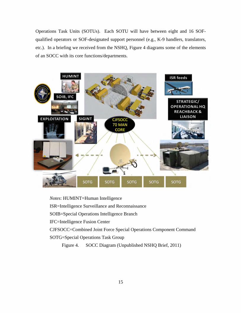
15
Operations Task Units (SOTUs). Each SOTU will have between eight and 16 SOF-
qualified operators or SOF-designated support personnel (e.g., K-9 handlers, translators,
etc.). In a briefing we received from the NSHQ, Figure 4 diagrams some of the elements
of an SOCC with its core functions/departments.
Notes: HUMINT=Human Intelligence
ISR=Intelligence Surveillance and Reconnaissance
SOIB=Special Operations Intelligence Branch
IFC=Intelligence Fusion Center
CJFSOCC=Combined Joint Force Special Operations Component Command
SOTG=Special Operations Task Group
Figure 4. SOCC Diagram (Unpublished NSHQ Brief, 2011)

16
The purpose of Chapter II was to discuss in detail NSHQ’s background—how it
was formed and how it was structured. In Chapter III, we review what has been written
about rapidly deployable headquarters.

17
III. LITERATURE REVIEW
Very little literature has been written about rapidly deployable headquarters for
military units. The literature that does exist fails to describe the layout of the
headquarters once deployed or the inventory of equipment used to support critical
functions, such as communications and life support. The existing literature that is
vaguely related to our study is focused on joint operations and the issues and concerns
that are raised not only when operating jointly as a multinational military force, but also
when different branches operate jointly.
Colonel Scott Schisser from the Institute for Defense Analysis discussed the
shortfalls of joint task force (JTF) headquarters in a 2001 paper entitled “Future Joint
Force Headquarters.” Even though his paper was written in 2001, he identified
challenges that are still prevalent in joint operations today. Schisser described how JTF
headquarters were unprepared and insufficient to meet command and control challenges.
Throughout his research, Schisser (2001) found that “regardless of the scale or scope ... a
common theme has been command control of joint forces” (p. 1). Lack of command and
control significantly affects the success and efficiency of the deployable joint task force
(DJTF). Schisser also concluded that the joint response teams (JRTs) should be
redesigned to effectively offer DJTFs with the tools and means to increase their self-
sufficiency in the field; furthermore, JRTs must stay informed to make quick and
appropriate decisions. The future of the DJTF should include cost-effective designs and
products that enhance the operational level of deployable task forces. Products need to
be quick to set up and take down, efficient, convenient for operations and personnel;
overall, they must be assets to the operations, missions, and desired outcomes.
Colonel Mike McGinnis (2004) published a report about the development of a
deployable headquarters for the NATO Response Force (NRF). In his report, McGinnis
identified many of the challenges that the JTF headquarters faced in Operation Stavanger.
As NATO moves forward in the development of multinational joint rapidly deployable
headquarters, leaders will need to preemptively emplace appropriate measures to avoid
issues deriving from the challenges that McGinnis articulated:
18
Varying Language Skills: NATO staffs have limited English language
skills.
Disparity in Military Experience: In a multinational headquarters, rank
alone is no guarantee that an individual assigned to a position possesses
the requisite education and experience to do the job.
National Caveats: NATO operations require significant consensus
building. All NATO nations must be in general agreement on the scope of
military operations before the NAC will issue an activation order to take
military action. Even after such an order is issued, nations may decline to
conduct specific operations invoking national caveats. Claiming national
caveats or other restrictions, individuals assigned to a NATO multinational
headquarters may elect to forego exercises and operations.
Intelligence Sharing, Computers, and Information Systems: Successful
operations depend on shared intelligence, good communications, and
interoperable computer and information systems across echelons’
headquarters. Working in a multinational environment creates complex
problems: deciding what intelligence can be shared, communicating with
different equipment, and operating on systems that are not compatible
with one another. NATO has not yet resourced a full suite of
interoperable communications, information systems, and infrastructure for
conducting such operations (McGinnis, 2004).
McGinnis emphasizes implementation of proper intelligence sharing practices,
computers, and information equipment in a multinational environment; moreover, this
equipment not only needs to be compatible at the headquarters level and above, but also
needs to be operable among all the units under the headquarters’ command. Given the
national caveats, clear communications on all levels help ensure that status and intent is
exchanged; clear communications increase the success of proper decision-making.
Within this equipment, further advanced language interpretation tools could be utilized to
help mitigate the complications that arise from language barriers. While training will
allow the operators to gain knowledge and experience, uncomplicated equipment helps

19
address the issues related to disparity in experience. Communications that allow the
headquarters and units the capability of reaching back to their home commands for
information further alleviate the problems that arise from inexperience.
A solid communications infrastructure is essential for successful command and
control. The Joint Staff Officer’s Guide, JFSC PUB 1 (Joint Forces Staff College, 2000),
states:
Command and Control functions are performed through an arrangement of personnel, equipment, communications, facilities, and procedures employed by a commander in planning, directing, coordinating, and controlling forces and operations in the accomplishment of the mission. (p. 3-52).
McGinnis discusses the consequences to not having good command and control. In many
cases, organizations that did not have effective command and control proved to be
costly—not just monetarily, but in terms of lives lost. A good example of what can go
wrong without proper command and control, from the top level to the lowest level, is
Operation Eagle Claw (Radvanyi, 2002). Operation Eagle Claw, a U.S. joint military
operation, failed to rescue U.S. hostages being held captive at the U.S. Embassy in
Tehran, Iran, on April 24, 1980. In an investigation of Operation Eagle Claw, Admiral
James L. Holloway and his investigative panel found that command and control was
excellent at the upper echelons, but became more tenuous and fragile at the intermediate
levels due to the interoperability of communication equipment used among the different
services (Kyle, 1990). Command relationships below the commander of the JTF were
not clearly emphasized. When compounded with the lack of compatible communications
equipment, these relationships were misunderstood under pressure. Lessons learned from
Operation Eagle Claw revealed the significance of ensuring that all levels of a joint task
force have the tools and training necessary to perform the mission; moreover, effective
command and control at all levels is critical for any military operation. As McGinnis
points out, command and control is more challenging for a multination joint task force to
establish. Implementation of a solid communications infrastructure with compatible and
interoperable equipment would help build the foundation for good command and control.

20
Both Schisser (2001) and McGinnis (2004) consistently discussed communication
as being one of the most important aspects of command and control. For NATO
organizations, communication is more difficult. English is the spoken language at
NATO; however, English is a second language for most NATO operators. The language
barrier can create problems and make communication extremely difficult. Technologies,
such as virtual communications, are being utilized by NATO to help overcome the
language barrier because they give individuals an opportunity to see facial and body
expressions while hearing a fellow operator’s voice.
In other joint operation cases, the use of different communication equipment was
also a problem. For example, in the 1983 U.S.-led invasion of Grenada, Operation Fury,
the coalition of forces had problems communicating. It was later documented that the
problems were attributed to the different services operating with dissimilar types of
communication equipment; the different types of communication equipment were not
compatible from Service to Service. Navy ships, within line of sight of Rangers and
airborne troops, could not initially receive or respond to their requests for fire support.
On two occasions, when Navy jets did respond, they attacked the wrong targets (Cole,
1983). Many of the member nations at NATO communicate with different equipment.
Lessons learned from Operation Fury serve as evidence for the importance of
standardizing communication equipment in joint operations to ensure compatibility—this
is absolutely vital for multinational units to operate jointly.
The articles reviewed in this chapter show how important it is to have a robust
command and control center to operate successfully in today’s battlefield. At the
forefront of the command and control issue is the ability to communicate effectively both
up and down the chain of command. With the new technologies available to today’s war
fighter from both military and commercial sources, the communication challenges
observed in the previous cases can be mitigated and eliminated.

21
The purpose of Chapter III was to analyze what has been written about rapidly
deployable headquarters. After our literature review, we can conclude that as NATO
moves forward in conducting multinational joint operations, it is imperative that
compatible and interoperable equipment, along with modern technologies, are being
utilized to ensure the good command and control that is necessary for missions to
succeed. In Chapter IV, we will begin laying out the problem that will be solved by the
development of a rapidly deployable headquarters at NSHQ.

22
THIS PAGE INTENTIONALLY LEFT BLANK

23
IV. THE PROBLEM TO BE SOLVED BY THE DEVELOPMENT OF A SOCC CORE
Chapter IV focuses on establishing the problem that will be solved with the
development of a Rapidly Deployable Special Operations Component Command (SOCC)
Core Concept for the NSHQ. We conducted research and analysis to examine and
determine the equipment and deployment configurations that will fulfill the mission
requirements of the SOCC Core. In addition, we analyzed alternatives to determine
which equipment types and configurations result in achieving the desired mission
capability at the lowest possible cost.
The NATO Special Operations Headquarters Framework Nation Primer states the
mission of NSHQ:
The mission of NSHQ is to serve as the primary point of development, direction and coordination for all NATO Special Operations related activities in order to optimize the employment of SOF. Optimization is the intent to make SOF as effective, efficient, and perfect as possible to enhance the probability of collaborative success when these national assets come together to operate in a combined manner. The addition of a directing function in the mission includes an operational command and control role through provision of the core for a deployable Special Operations Component Command when directed by SACEUR. (NSHQ, 2009a)
The addition of an operational command capability in the mission includes an
operational command and control role through provision of the “core,” which is an
advanced party of 70–150 personnel, for an organic, rapidly deployable Special
Operations Component Command when directed by the SACEUR. The NSHQ does not
currently have the ability to provide NATO with a rapidly deployable asset package,
which would include robust operational command, control, communication, computers,
and intelligence (C4I) capabilities, equipped with organic special operations forces (SOF)
enablers. Possessing a rapidly deployable SOCC Core would be a sound step toward
establishing and ensuring interoperability among allied SOF units and commands, and
enhance the employment of NATO Special Operations forces.
24
The United States is the framework nation of NSHQ. With this position, the
United States has the responsibility to provide 100% of the initial funding and support for
the SOCC Core concept. This includes the initial issue of equipment required for a
rapidly deployable headquarters element. Once the initial issue of equipment is
purchased and begins to be fielded, all 28 NATO member nations will share in the
sustainment, operational, and maintenance costs of the SOCC Core.
In the NSHQ Biennial Review, in a section titled “Deployable CJSOCC Core,”
there is an explanation for this rapidly deployable concept: “Currently, unlike NATO’s
Land, Maritime and Air capabilities within the military structure, the Alliance has no
assured, deployable capability to provide C2 for NATO SOF. By capitalizing on the
personnel currently assigned to the NSHQ, an opportunity exists for the proposed NSHQ
to realize a more cost-effective use of personnel, without growing NATO’s Peacetime
Establishment (PE), while enhancing SACEUR’s crisis response options, through the
provision of a CJFSOCC [Combined Joint Force Special Operations Component
Command] (Core) element. During peacetime or crisis, the NSHQ may be directed by
SACEUR to assign the CJFSOCC (Core) to any NATO Command Structure (NCS)
headquarters for CJTF operations and/or exercises. This CJFSOCC (Core), when
deployed for NATO approved operations, would continue to be under operational
command (OPCOM) to SACEUR, and under operational control (OPCON) to the
operational commander; the CJFSOCC would exercise OPCON of assigned forces. This
Core element relies on troop contributing nations to provide augmentees in accordance
with standard NATO processes to transition the CJFSOCC from a short term to an
enduring capability” (NSHQ, 2010c).
There are currently seven nations which are trained and equipped to field a
deployable HQ or SOCC. This means that they possess the operational SOF experience
and knowledge to control SOF operational elements for employment purposes. They also
possess limited issue communications equipment which could be used to control and
oversee those operations. Those seven nations are the United States, the United
Kingdom, France, Spain, Italy, Germany, and Turkey. Turkey may not be considered
capable or willing to provide SOCC Core capabilities past 2011. Poland is attempting to

25
become the eighth nation that is SOCC capable. Being SOCC capable does not mean that
a country is a designated SOCC HQ. This just means that the country is capable of
running the SOCC Core once the equipment is purchased for it (NSHQ, 2010e).
In a SACEUR-signed document called the Bi-Strategic Command, there was an
agreement and requirement to have 19 SOCC-capable countries. With only seven
currently capable, this has created a gap of 12 countries desperately needed by NATO
and NSHQ to be SOCC capable (NSHQ, 2010e). More nations that are SOCC capable
would mean more HQs that could be fielded by NSHQ on behalf of NATO. There are
currently 29 situations, or possible contingencies, that NATO would respond to. Out of
the 29, the NATO Response Force (NRF) would only respond to seven. This leaves a
gap of 22 possible worldwide contingency situations to which NSHQ could respond
(NSHQ, 2010e).
The NATO strategy MC 400/2 basically states that NATO will not specifically
dictate how each country conducts SOF missions, but that each country should be capable
of meeting seven key requirements. The requirements are force readiness, infrastructure
that is able to operate an effective C2 element, an effective intelligence system,
effectiveness in engagement, the ability to sustain organic logistics, the ability to be
deployable and mobile, and survivability for the environment in which they are operating.
These are the key requirements, but they are basic standards from the perspective of
operating a SOCC Core (North Atlantic Military Committee, 2000).
NSHQ is a multinational organization of 27 countries. Having this many
countries in an organization requires set standards for the equipment used in an operation,
to ensure compatibility and interoperability. While requiring each country to meet these
standards is a major challenge, it is essential to the effective operation of a SOCC Core.
The SOCC Core is an advance party of 70 to 150 personnel. This is a rapidly
deployable HQ that is organic to NSHQ and should be capable of overseeing command
and control of six SOTGs and one SOATG. It should be capable of deploying in less
than 14 days. It should also be capable of traveling by sea, air, or land. All the
equipment of the SOCC Core must be transportable by CH-47 helicopters.
26
The environment in which the SOCC Core will operate is ever-changing; thus, the
camp of the SOCC Core must be flexible and versatile. The camp must also be capable
of supporting the three principal tasks of NSHQ and NATO SOF: direct action (DA),
special reconnaissance (SR), and military assistance (MA). NSHQ and the SOCC Core,
when fully operational and capable, could be tasked with conducting these three core
tasks anywhere in the world and in any environment or climate.
The varieties of climatic conditions this camp may encounter make it necessary
for the camp to meet NATO-directed guidelines, which are addressed in Chapter V. In
terms of the environment, the camp must be capable of sustaining the force when
operating in the following threat conditions: hostile, uncertain, and benign. These
conditions encompass the wide spectrum of possible operations and environments—.from
a full-blown, mature warzone to a third world, underdeveloped country with little threat
to the force. The SOCC Core camp must also be capable of having itself transported via
C-130 from Belgium to the operating area, then transported via CH-47 for the last leg to
the operational staging point for the SOCC Core.
The four sections into which the camp will be broken down are the Operations
Center (OPCEN), All Source Center (ASC; intelligence fusion node), Support Center
(SUPCEN; provides Real Life Support [RLS]), and the Signals Center (SIGCEN,
communications). The four sub-components will provide the needed versatility and
flexibility for NSHQ to pick and choose from its parts and pieces to develop capability-
based packages for each of the three SOF tasks/core missions.
The three options for the camp that the thesis team is choosing among are 1)
commercial off-the-shelf (COTS) equipment, 2) items from a military logistics/supply
system, or 3) a hybrid of these two options. The thesis team will specify which
equipment that should come from each source of supply. Structural options for the camp
which are available are hard container structures, which are currently being fielded by
NSHQ; soft container structures, which are currently being fielded by SOCOM; and
cheap soft structures that NSHQ could leave behind after a mission (foam structures).
Another option is for a camp to use a combination of hard and soft structures. NSHQ
could also deploy to an area with existing structures and buildings; this may include a

27
shipboard option, which would place the SOCC Core on a ship with its containers. All of
the equipment has to be lightweight and air portable.
The NATO Special Operations Forces Study (NSSC, 2008) describes the major
requirements of a NATO CJFSOCC, which is essentially a SOCC Core: “The CJFSOCC
headquarters has a combined and joint staff structure normally formed around a Special
Operations Forces Fusion Node (SOF FN) nucleus providing, as a minimum, the
commander, key staff personnel, base life support capabilities, and the command, control,
communications, computers and intelligence (C4I) structure for operational control
(OPCON) of all SOF in a designated theatre of operations. The CJFSOCC normally
controls between two and six JSOTFs, SOTGs and /or SOATGs. Forces may also
include conventional force under OPCON of the CJFSOCC” (pp. C4–C5).
Then there is a list of criteria for the CJFSOCC. It must be able to conduct
NATO J1-J8 functions, advanced crisis response, time sensitive planning, and theatre-
level campaign planning. It must be able to plan, coordinate, and direct special
operations separately or as part of a larger force. It must be able to develop operational
intelligence and integrate ISR platforms, sensors, and HUMINT into theatre-level
collection plans. It must be able to operate, manage, and maintain NATO operational-
level communication and information systems (CIS) down to SOTG level. It must
manage the force protection for the SOCC Core camp. It must coordinate and oversee
CSS functions for the SOTGs. It must have all classes of supply to sustain itself for at
least 10 days. Lastly, it must be able to direct special operations organically on its own
or as part of a larger force or HQ structure” (paraphrased from NSCC, 2008, pp. C4–C5).
The purpose of Chapter IV was to lay out the problem. In Chapter V, we will
provide the solution.

28
THIS PAGE INTENTIONALLY LEFT BLANK

29
V. THE MATERIAL SOLUTION FOR THE RAPIDILY DEPLOYABLE SOCC
The NSHQ is planning on procuring material for a rapidly deployable
headquarters. The procurement plan is broken down into four sub-components that
correspond to the sub-components that comprise the NSHQ SOCC Core. These sub-
components are SUPCEN (Support Center), OPCEN (Operations Center), SIGCEN
(Signal Center), and ASC (All Source Center).
The following considerations will be included in the Procurement Plan (NSHQ,
2011):
1. Maintenance and Supply Support—establish near-term maintenance
requirements to include spare part stocks and availability. Determine
sustainment and life cycle replacement of parts and of systems.
2. Packaging, Handling, Storage, and Transportation—identify designs and
methods to ensure the systems are preserved, packed, stored, handled and
transported properly.
3. Support Equipment—identify all equipment required to support operations
and maintenance of the system.
4. Technical Data—identify scientific and technical information used to
support the systems.
5. Training and Training Support—determine requirements to acquire
training devices and conduct training of operators and maintenance
personnel.
6. Facilities—identify real property and storage containers required to
support each of the systems.
When building the life-support features of this rapidly deployable camp for this
thesis, we considered many factors and characteristics, including, but not limited to,
weight, size, cubic dimensions, ease of setup, durability, transportability, functionality,

30
and cost. During this study, our team visited numerous operational units, along with
several manufacturers, to gather our data. In this study, we compare four manufacturers:
Alaska Structures, Base-X, DRASH, and Weatherhaven. These companies are by no
means the only available manufacturers of military- style camps, but they are the vendors
of camps that are predominantly used for not only SOF operations, but also for other
combat units throughout NATO and the U.S.
When evaluating each camp manufacturer, we considered several factors. In
Table 1, we present a general overview of these factors. Later in this thesis, we address
the characteristics of the products of each vendor and explain the specific factors in more
detail. The grading and evaluations are taken from our visits to the various units and
manufacturers of these camps. The equipment manufacturers provided the weight, size,
cube, and cost information. Information regarding the ease of setup, durability,
transportability, and functionality came from both the manufacturer and from the current
users of the particular camp. The manufacturers needed to meet or exceed specific factors
in order to be considered for selection. We used the following guidelines and
specifications we received from the NSHQ’s J4 in our evaluation of each camp
manufacture.
1. Environmental threats and conditions: a. Snow load of 10 lb (5 kg) per sq ft (m) for 12 hours without damage to the frame or structure
b. No observed leakage during wind-driven rain of 2 in. (5 cm) of rain
per hour at 35 mph (56 km/h) for 30 minutes c. Ability to withstand wind load of 55 mph (89 km/h), with gusts up to 65 mph (105 km/h) d. Operational at -20–120 °F (-29–49 degrees °C) e. Openings for 4 in. (10 cm) diameter flue stack and/or 16 in. (41 cm) diameter ECU ducts f. Sufficient natural ventilation to support recommended number of occupants and minimize condensation g. Ability to be configured to provide entry and egress under blackout conditions h. Ability to be erected on rough, uneven, or sloped terrain

31
2. Detection threats: a. Matt or dull finish to fabric and support systems b. Fabric in colors of green, tan, or white c. Not observable at night with light inside 100m with naked eye or 300m with night-vision goggles d. Fabric pigment matches infrared reflectance of intended climate (i.e., temperate, desert, or arctic) e. Compatible with standard camouflage net systems 3. Safety: a. Flame resistance/char length/melt drip to meet ASTM d-6413-99, paragraph 3.4.7, self-extinguishing within 2 seconds after exposure to the flame source for 12 seconds in both the warp and fill directions. The damaged char length shall be less than 50% of the sample length of 12 in. (30.5 cm). No melt drip. b. No toxic materials used in paints or preservative coatings for frame or fabric finish or coatings. c. Meets human factors requirements for soldier lift (i.e., 37 lb/16.8 kg/ soldier) 4. Durability: a. Can withstand 50 cycles of erect and strike for one year b. Sustainable with repair parts, manuals, and logistical support c. Capable of two years of continuous use 5. Other considerations: a. Insect screens, door openings, vestibules, and compatibility with soft and hard flooring b. Erected in all environmental conditions c. Transportable on 463 L pallet and by C-130, cargo HMMWV, FMTV, and LMTV d. Spare and repair parts available through contractor

32
A. SUPCEN (SUPPORT CENTER), COMPARISONS AND CHARACTERISTICS SHELTERS: ALASKA STRUCTURES
We visited several U.S. Army SOF units in Fort Bragg, NC, and a U.S. Naval
Special Warfare Command (NAVSPECWARCOM, NAVSOC, or NSWC) in San Diego,
CA, where we met not only the users, but also the manufacturer of Alaska Structures
shelters. We compared and considered several Alaska Structures models that could be
used when building the camp. The first option we looked at was the Alaska Gable
Shelter, a gable-roof, soft-sided structure (Figure 5). The Alaska Gable Shelters are
designed to be light and compact for rapid deployment, quick setup, and improved
transportability. (Initial training for these structures is provided by Alaska Structures.)
When assembled, the Alaska Gable Shelter measures 18 ft (5.5 m) wide and is 9 ft (2.7
m) at its apex, and is available in multiple lengths. The standard shelter is 18 ft x 26 ft
(5.5 m x 7.9m), weighs 620 lb (281.2 kg), and can be fully operational in fewer than 15
minutes with six trained personnel. During our visit to NSWC in San Diego, the Seabees
who set up the camps for NSW said it took three or four men about .5–.75 hours to set up
a tent with structuring, wiring, liner, etc. The Alaska Gable Shelters have a 20-year shelf
life and are designed for up to 10 years of extended use in the field (Structures, Alaska
Structures, 2011).

33
Figure 5. Alaska Gabled Structures
The second option we looked at by Alaska is called the Alaska Small Shelter
System (AKSS). This shelter is 20 ft wide x 32.5 ft long x 10 ft high (6.1 m wide x 9.9 m
long x 3 m high) and is soft sided. The AKSS can be connected end-to-end, side-to-side,
or end-to-side to create multi-shelter complexes. All AKSSs come with a cover system,
complete insulation system, a non-slip floor, a 30 in. x 80 in. (76 cm x 203.2 cm) hard
door, four windows, plenum, an incandescent light string, and a quick-connect electrical
harness with 24 outlets (Structures, Alaska Structures Small Shelter System, 2011).
Additional standard features of the AKSS models include side windows, side entries, and
stovepipe flanges.

34
In terms of their ability to withstand environmental conditions, Alaska Structures’
soft-sided shelters, both the gable roof system and the AKSS, far exceed the requirements
we received from the NSHQ for wind and snow loads. The gable-roof system can
withstand snow loads of up to 125 lb/sq ft (56.7 kg/m2), and it tested successfully for
wind loads of up to 120 mph (193 km/h). The AKSS successfully withstood 70 mph
(112.7 km/h) wind loads with 80 mph (128.75 km/h) gusts, and it also successfully meet
a 20 lb/sq ft (9 kg; PSF) snow load (Structures, Alaska Structures, 2011).
Both the gable structure and the AKSS can be customized with entry vestibules
that can help reduce dust entry into the shelter as well as reducing light exposure at night,
a functionality that meets the light restrictions stated previously. Additional options that
are available for both shelters include containers, one-piece liners, fluorescent lights,
European lighting and electrical distribution systems, and generators. Both styles of
structures were used operationally, and the structures’ capabilities and quick erect
systems were noted during OEF and OIF and were reported to far exceed the
requirements imposed by the Air Force, Army, USSOCOM, and the British Mod in
extreme heat, wind, and sand (Structures, Alaska Structures, 2011). The users at several
Fort Bragg commands were extremely happy with the overall operation of the Alaska
Structure products, especially with their transportability (Figure 6), ease of setup,
durability, and comfort.
Figure 6. Transporting the AKSS (Alaska Structures)
Transporting the AKSS 41” wide x 102” long x 49” high
104 cm wide x 259 cm long x 124.5 cm high
One complete Alaska Small Shelter per container
Four containers per 463 L pallet position

35
Alaska has also developed two new energy-efficient products that will
significantly reduce the carbon footprint of base camps, decreasing the amount of fuel
required to heat and cool any Alaska Shelter. These new eco-friendly systems are
available for all Alaska Shelter models, and they are called Enerlayer and Alaska Solar
Fly (Figure 7). The first Alaska Enerlayer sits in between the outer cover and inner liner
of the structure. With the Enerlayer installed, there is a 35% reduction in the heat
required to maintain a 70 °F (21 °C) interior temperature at -25 °F (-32 °C) ambient
temperature, a 22% reduction in the air conditioning required to maintain a 70 °F (21 °C)
interior temperature at +125 °F (52 °C) ambient temperature, a further 33% reduction in
the air conditioning required when used in conjunction with AKS Solar Fly. These
systems save up to 2,650 gal (10,031 L) of fuel per year (per shelter/5-ton ECU;
Structures, Enerlayer Alaska Structures).
Alaska Structures also offers a variety of Environmental Control Units (ECUs),
including a 2.5-ton unit, a 5-ton unit, and a 10-ton unit. Each Alaska ECU is available in
either a U.S. version (3-ph, 208V, 60Hz) or an EU version (1-ph, 230V, 50Hz). AKS also
offers a 5-ton split system for NBC applications. Alaska’s ECUs come with forklift
pockets on all four sides, one set of 36-in. long insulated ducts, a 25-ft power cable with a
U.S. military cannon plug connector, and a 60-day spares/repair kit. Alaska ECU options
include wheels kits, various lengths of insulated ducts, and remote control units
(Structures, Alaska Structures ECUs, 2011).

36
Figure 7. AKSS Shelters with Solar Fly (Alaska Structures)
Alaska Structures provides 24/7 emergency customer service, technical support,
and product information via phone, e-mail, or on location. Most spare and replacement
parts are shipped within 24 hours to locations around the world.
B. HDT GLOBAL BASE-X AND AIR BEAM STRUCTURES
Headquartered in Solon, Ohio, HDT Global is the manufacturer of the Base-X
shelters. We studied their products, which are used by the U.S. and NATO military units,
civilian governments, and commercial customers around the world. We observed the
Base-X structures at the U.S. Marine Corps 1st Marine Expeditionary Force (MEF) unit at
Camp Pendleton, CA, and at NSWC in San Diego, CA. A key characteristic of Base-X
shelters is their lightweight folding frame, specifically developed to reduce the setup time
of this tactical soft-walled shelter system. (Initial training for this system is provided by
HDT Global.) The folding frame design gives the system its strength and helps in the
ease of setup. The system has the strength required to meet specifications, and the
lightweight frame keeps the system to a minimum in weight and size, while still making
it mobile and easy to deploy. The folding frame shelters range in size from personal tents
to corps-level command and control (C2) complexes.

37
Figure 8. HDT Base-X® Model 307 Shelter Specifications (HDT Global)
The HDT Base-X® Model 307 (Figure 8) is a mid-sized shelter with an interior
clear span of 18-ft wide x 35-ft long (5.49 m x 10.67m) with eight entry and egress
points. This shelter houses 14-18 personnel, and it could also be used for mid-sized
command and control (C2), medical, communication, logistics operations, and private
offices. The Base-X® Model 307 comes as a sleeping kit (Part# 60307GPSLP-KTTN)
(Figure 9), which consists of the following components:
1. 1-307 Ready-Fold Flooring
2. Two Light Kits (set of two)
3. Ready-Roll Flooring

38
Figure 9. Model 307 Ready-Fold Floor (HDT Global)
The 307 has electrical outlets every five ft (1.5 m) and hang points every five ft
(1.5 m) that can hold up to a 100-lb (45.4 kg) weight-load at each point (Global, HDT
Base-X Model 307, 2011). It has an integral liner with floor and HVAC plenum, a
relatively low weight, and cubic size. In addition, the personnel requirements for setup
and field maintenance are minimal. This shelter is also energy efficient when utilizing the
HDT Solar Shade Fly (Figure 10) which provides an additional layer of solar protection,
reducing shelter interior temperatures and temperature gradients, and lowering the fuel
consumption associated with environmental control. Use of the Shade Fly with HDT’s
shelters has been proven to reduce internal shelter temperatures by 10–18 °F (5.5–10 °C;
Global, Shade Fly, 2010).

39
Figure 10. HDT Global Solar Shade Fly (HDT Global)
HDT’s radiant barrier (Figure 10), which helps to improve conductive,
convective, and radiant heat transfer, a beneficial feature to have in some of the extreme
climates of the world where military forces deploy. Both of these barriers can help
reduce the amount of energy required to heat and/or cool these shelters as well as to
reduce the logistical burden on the deployed forces. Both barriers were tested by HDT
and they claim that the new barrier lowers the shelter’s interior temperatures by 10–18 °F
(5.5–10 °C) in non-ECU cooled shelters, and it lowers the temperature gradients up to
63% in non-ECU cooled shelters. In addition, having these energy efficient products
installed on the shelters reduces ECU run times to 70% below normal, thus reducing fuel
consumption. The ECU-cooled shelters are up to 10.8 °F (6 °C) cooler when using the
Shade Fly (Global, HDT Shade Fly, 2011). The radiant barrier is currently being used in
the field by the Marines.

40
As a possible standalone operation, energy sources and supply line management
are critical to consider, and HDT had some interesting options to offer in the use of
alternative energy sources. One option of particular interest is their expeditionary power-
grid management technology that makes the most of every watt, distributing power
efficiently throughout the camp to where it is needed and conserving it when it’s not. The
HDT Balance of Systems (BOS)1, shown in Figure 11, utilizes this technology to manage
the distribution of power harvested from alternative energy resources, such as solar, shore
power, and generator power. In addition, the BOS can interface with tactical vehicle
power via a NATO connector from the battery of a tactical vehicle. The battery array,
(Figure 11) can be added in series for increased generator run time (Global, HDT Balance
of Systems, 2011).
1 This item and the technical data and defense services directly related to this item are subject to the International Traffic in Arms Regulations (ITAR), 22 CFR § 120–130 and may not be exported to any foreign destination or any foreign entity or foreign national, inside or outside the United States, without prior approval by the U.S. Department of State. (Global, HDT Balance of Systems, 2011)

41
Figure 11. HDT Balance of Systems (BOS) and Battery array (HDT Global)
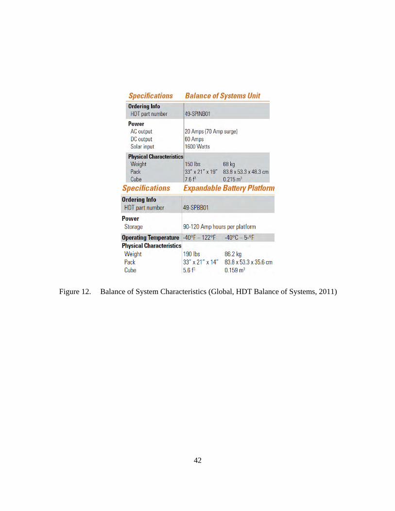
42
Figure 12. Balance of System Characteristics (Global, HDT Balance of Systems, 2011)

43
Figure 13. HDT Alternate Energy Solution (HDT Global)
C. AIR-SUPPORTED TEMPER HDT AIR BEAM STRUCTURE
Another shelter option from HDT is their high-pressure Air Beam Structure,
(Figure 14). The Air Beam Structure has several key advantages as a shelter system,
which includes its strength, durability, rapid deployment capability, and minimal
manpower requirements. Another key benefit is the low life cycle cost for each unit due
to the small logistics chain and parts count. The durability of these shelters has been
demonstrated in nearly 200 consecutive Air Beam shelter erection-strike cycles without
incident. The Air Beam- series shelters come in three models that are 21-ft (6.4 m) long
and four models that are 32-ft (9.8 m) long. These models have identical 10-in. (25.4 cm)
diameters and a 20-ft (6.1 m) clear span. Standard models range in size from 430–640 sq
ft (131.1–195.1 m2) and are offered in a variety of configurations. The Army selected the

44
HDT Air Beam Shelter (Air Supported temper types) for Force Provider, their premier
base camp (Global, HDT Global Air Beam Shelter System, 2011).
Figure 14. HDT Air Beam Shelter System (HDT Global)
We did not personally see the Air Beam setup at any of the sites we visited, but,
based on the idea and concept, we expect this system would be user friendly and easy to
deploy and erect. The shelter is laid out and staked to the ground at just four anchor
positions. The AirBeams are then inflated simultaneously with a commercial air
compressor that comes with the package. The company states that two people can deploy
the shelter in fewer than ten minutes. The shelter is deployed and struck with the
prepositioned inflation hoses. The Air Beam’s specific characteristics include the
following: weight (including the compressor) is 646 lb (293 kg); packed volume is 6.9 cu
yd (5.3 m3); wind load is 64.4 mph (103.7 km/h); and snow load is 10 lb/sq ft (4.5kg/m;
Global, HDT Global Air Beam Shelter System, 2011).
HDT Global provides 24/7 customer service, technical support, and product
information via phone, e-mail, or on location. Most spare and replacement parts are
shipped within 24 hours to locations around the world.

45
Note. We received these drawings from an HDT Global Sales representative.
Figure 15. DRASH Structure System
D. DRASH STRUCTURE SYSTEM
DRASH’s headquarters and manufacturing facility is located in Orangeburg, NY.
Their systems are currently used by all branches of the U.S. military and by the armed
forces of Australia, Austria, Germany, Israel, Japan, Norway, Singapore, Spain, Turkey,
and the United Kingdom. More than 17,000 shelters and over 7,500 trailers have been
deployed worldwide with U.S. and NATO forces (DRASH, DRASH Brochure, 2011).
We met with representatives from DRASH in Fort Bragg, NC, during an exercise with
the 82nd Airborne. The 82nd Airborne had its command and control setup for the
exercise and was in the process of setting up the remaining camp.
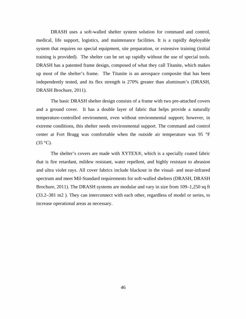
46
DRASH uses a soft-walled shelter system solution for command and control,
medical, life support, logistics, and maintenance facilities. It is a rapidly deployable
system that requires no special equipment, site preparation, or extensive training (initial
training is provided). The shelter can be set up rapidly without the use of special tools.
DRASH has a patented frame design, composed of what they call Titanite, which makes
up most of the shelter’s frame. The Titanite is an aerospace composite that has been
independently tested, and its flex strength is 270% greater than aluminum’s (DRASH,
DRASH Brochure, 2011).
The basic DRASH shelter design consists of a frame with two pre-attached covers
and a ground cover. It has a double layer of fabric that helps provide a naturally
temperature-controlled environment, even without environmental support; however, in
extreme conditions, this shelter needs environmental support. The command and control
center at Fort Bragg was comfortable when the outside air temperature was 95 °F
(35 °C).
The shelter’s covers are made with XYTEX®, which is a specially coated fabric
that is fire retardant, mildew resistant, water repellent, and highly resistant to abrasion
and ultra violet rays. All cover fabrics include blackout in the visual- and near-infrared
spectrum and meet Mil-Standard requirements for soft-walled shelters (DRASH, DRASH
Brochure, 2011). The DRASH systems are modular and vary in size from 109–1,250 sq ft
(33.2–381 m2 ). They can interconnect with each other, regardless of model or series, to
increase operational areas as necessary.
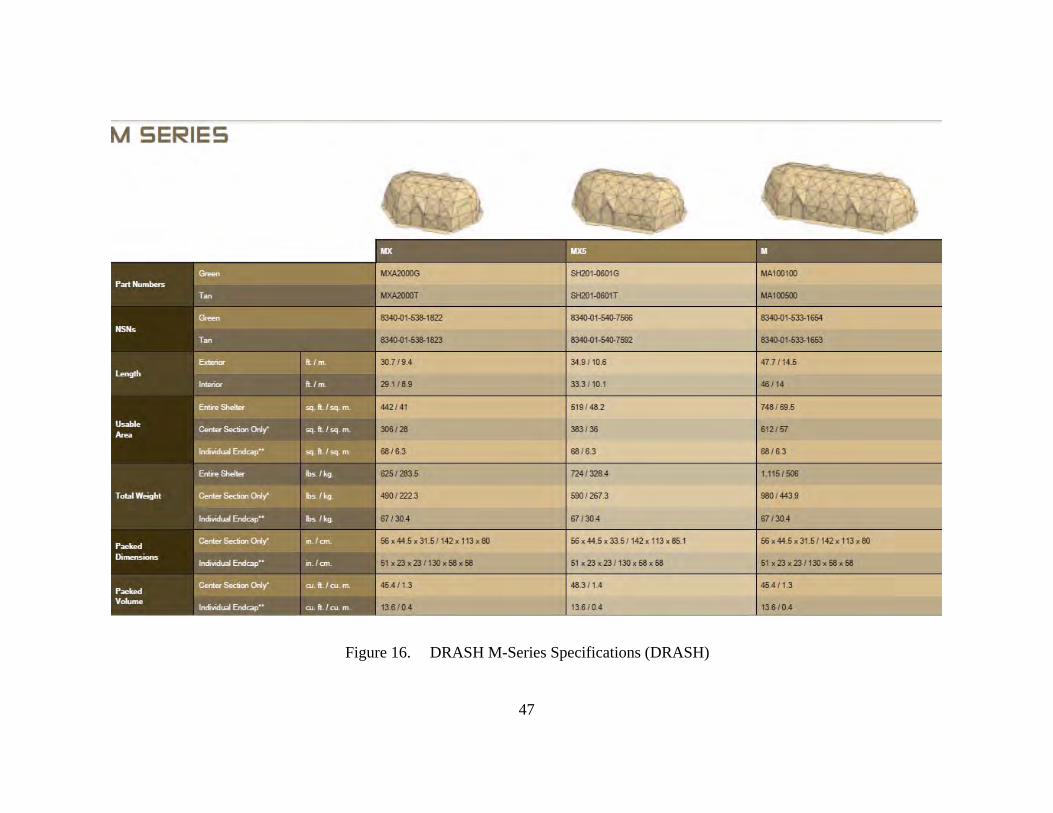
47
Figure 16. DRASH M-Series Specifications (DRASH)

48
DRASH has several models to choose from (Figure 16). One of the models we
observed in the field was from DRASH’s M Series (Figures 15 and 17). The M Series
shelters include one of DRASH’s military dome tents with an interior width of 18 ft (5.5
m) and an interior height of 9.7 ft (3 m). These shelters come in three basic models and
in varying lengths. In addition, the M Series shelters can be lengthened to increase an
operating area by removing the shelters’ end caps and adding additional center sections.
The M Series shelters pack down to less than 2% of their deployed size for easy transport
(DRASH, DRASH M Series, 2011). The DRASH M Series shelters can operate in
temperatures ranging from -50– +131 °F (-45.5–55 °C). The M Series shelters can be
assembled in approximately 15 minutes with about four to six trained individuals
(DRASH, DRASH Shelters, 2011). The units at Fort Bragg took slightly longer to set up
the shelters, because several more junior troops assembled the structures. DRASH had an
area representative on site, assisting the soldiers and answering questions. DRASH
provides 24/7 customer service, technical support, and product information via phone, e-
mail, or on location. Most spare and replacement parts are shipped within 24 hours to
locations around the world.

49
Figure 17. DRASH Series M Style Shelters (DRASH)
DRASH’s power and environmental controls can be integrated with a Utility
Support Transport (UST) trailer (Figure 18) that provides a seamless power package and
environmental control system for deploying in extreme conditions. UST trailer models
include Genset outputs ranging from 5–33 kW and/or 5-, 8-, or 12-ton Environmental
Control Units (ECUs) with an integrated strip heater. The trailer has lift points for sling
loading by a CH-47. The system is mounted on a large trailer that has both benefits and
challenges.
One of the benefits of the system is that it is compact on the trailer, and the trailer
has additional storage space for other shelters, which makes for easy transport. That is
also one of the problems with the type of camp we are setting up. The trailer that
DRASH’s power and environmental control system sits on is very large. This trailer is

50
ideal for a large operation that has semi-trucks delivering equipment to the camp;
however, without a large vehicle to move the system, the shelters are immobile and
cannot be moved into an ideal position. This system was designed to operate in an all-
terrain area acceptable for military vehicles and to track behind, but it was not necessarily
designed to be airdropped into an environment.
Figure 18. DRASH UST Trailer (DRASH)
If deploying with vehicles, the DRASH UST trailer with the shelters attached
(Figure 17) can be towed via HMMWV, LMTV, FMTV, or non-tactical vehicles.
DRASH shelter systems are also certified for transport via military sea vessels and
aircraft. The shelters can be packed on a 463 L pallet for easy deployment, making them
flexible for shipping. The DRASH shelters meet all U.S. military standards, and they
have been tested at the Aberdeen Test Center (ATC) and the Nevada Automotive Testing
Center (NATC) (Figure 19).

51
DRASH DURABILITY TESTING
Test Criteria/Shelter Series S Series XB
Series M Series J Series
Rain Able to withstand 2 inches per hour of free falling and blowing rain for 30 minutes without intrusion of water into the shelter.
PASSED PASSED PASSED PASSED
Wind Able to withstand a steady wind of 55 mph with gusts up to 65 mph.
PASSED PASSED PASSED PASSED
Temperature Able to sustain inside ambient temperatures of +40F to +80F within an hour when subjected to extreme high and low temperature ranges of -50F to +131F.
PASSED PASSED PASSED PASSED
Durability Able to withstand a minimum of 36 erect/strike cycles without structural damage.
PASSED PASSED PASSED PASSED
Blackout Interior shelter lights not visible during ingress/egress within 100 meters with the naked eye, or within 300 meters with night vision goggles.
PASSED PASSED PASSED PASSED
Snowload Able to withstand 10 lbs/sq.ft. of snow load for 12 hours without damage while using All Weather Kit.
PASSED PASSED PASSED PASSED
Figure 19. DRASH Durability Testing Results (DRASH, DRASH Brochure, 2011)
E. WEATHERHAVEN STRUCTURES
Weatherhaven corporate headquarters is located in Vancouver, Canada, and the
company has manufacturing facilities in South Africa and South America. Our team
visited Weatherhaven’s headquarters and met with their representatives in Vancouver.
We took a tour of their facilities and viewed many of their products and shelters. The
company stressed to us that Weatherhaven builds to their customers’ requirements and
specifications. Their representatives showed us several examples where a customer asked
Weatherhaven to build an item to meet a certain requirement, and the company’s
designers and engineers did just that.

52
Figure 20. Weatherhaven Shelter (Weatherhaven)
Weatherhaven fabric shelters (Figure 20) and systems can be packaged for
shipment in standard 20-ft ISO shipping containers or on pallets for cargo aircraft of any
size. Weatherhaven shelters do require a few specialty fitted tools for assembling and
disassembling their shelters. (Initial training is provided by Weatherhaven.) The
components of the shelter systems—such as the flooring and the electrical and
mechanical systems—are also specifically designed to facilitate an easy set-up and
teardown. Weatherhaven claims their shelters and systems have been used in the field for
projects that have lasted 15–20 years (Weatherhaven, Weatherhaven Military Products,
2011). Weatherhaven’s Modular Tentage System (MTS) comes in a variety of sizes that
can be connected with other shelters to form larger complexes (Figure 21). The MTS is
commonly used for accommodation, ablutions, kitchens, laundries, command posts,
workshops, and medical facilities.

53
Figure 21. Weatherhaven MECC and Soft-Sided Shelter (Weatherhaven)
The Series 4 is another Weatherhaven soft-sided and has been used for over 20
years by various countries. It is a shelter that is in use worldwide in all climates,
including polar regions. Weatherhaven’s Solarshade system is similar to the
environmental control systems that Alaska Structures and Base-X offer. Like the other
two manufacturers’ systems, the Solarshade is designed to reduce the internal
temperature within the shelter in extreme environmental conditions. The Solarshade is
designed to be used in combination with a Weatherhaven shelter when deployed in areas
of extreme direct solar radiation. The Solarshade also helps to prolong the life of the
Weatherhaven shelter by reducing its exposure to harmful radiation and solar gain. The
Solarshades also helps reduce the demand on climate control systems by blocking
between 66–93% of solar rays (Weatherhaven, Weatherhaven Shelters, 2007).

54
F. HYGIENE SYSTEMS AND KITCHENS
We consulted several sources to figure out the correct solution for constructing
hygiene facilities. We received several different answers, and we concluded that it
depends on the environment the camp deploys to. We received a wide range of solutions,
everything from a best case scenario (use the facilities already in place in country, such as
buildings, hangars, etc.) all the way down to a worst case scenarios (digging ditches and
burning the waste). The options we explored scratch the surface in this area, but, to
provide an accurate solution, we would have needed to make too many assumptions. The
ideal hygiene solution must be determined during mission planning, but our options
provide a good base point to build from and could be deployed in any theater, in any
circumstances, with the right support.
1. Alaska Structures Ablutions
Alaska Structures offers a four-person and a one-person shower system, as shown
in Figure 22. Their system includes one 20-ft x 19.5-ft (6.1 m x 5.9 m) Alaska Structures
shelter, one 2.5-ton Alaska Structures FCU, one lighting/electrical kit, one three-basin
sink, four Alaska Structures shower-in-a-box shower stalls, a hot water heater, a self-
priming pumping system, 2000-gal (7,571 L) potable and grey-water bladders, a
wastewater drainage pump, a ventilation fan, and a plug- and-play quick-connect hose
kit. The shower system can handle over 100 showers per day (Structures, Alaska
Structures Readiness Shelter Systems, 2011).

55
Figure 22. Alaska Structures Shower System (Alaska Structures)
2. DRASH Mobile Hygiene System
The DRASH Mobile Hygiene System includes private shower stalls and a
common wash area with wash basins and benches. A rigid-wall containment berm sits on
the inside perimeter of the shelter to ensure that runoff water is contained within the
entire system. Raised flooring sits inside the berm, along with a wastewater pump system
that automatically turns on when water is present and shuts off when the water level is
below a quarter inch. Water can then be delivered from any fixed, pressurized water
source, and from a fresh-water bladder or body of water via a pressurized pump system.
The water can be heated using a diesel water heater.
The DRASH G2 Water Heating System is a 425,000 BTU, self-heating,
thermostatically controlled system. One of the benefits of this DRASH water heating
system is its ability to use multiple fuel sources (diesel, kerosene, home heating oil, and

56
JP4). The system produces a flow rate of up to 28 gallons per minute (106 L per minute)
with a 10-gal on-board fuel tank with drain plug (DRASH, DRASH Mobile Hygiene
System, 2011).
Figure 23. DRASH Hygiene System (DRASH)
The DRASH shower shelters are composed of fire-retardant, mold- and mildew-
resistant, waterproof covers. The frame is manufactured from Titanite, and the shelter is
pre-plumbed into the interior of the shelter frame, making it easier to set up and take
down. The showers are supplied by 35-ft (10.67 m), abrasion-resistant hoses that connect
to the water heater.
3. Weatherhaven Support Facilities
Even though Weatherhaven has a soft-side shelter version for their ablutions,
kitchens, and laundry facilities, their hard-side container version is top of the line and the
best we have seen. In camp applications, the Weatherhaven MECC is commonly used for
ablutions, kitchens, and laundry facilities. One of the big benefits of the Weatherhaven
solution is its stainless-steel interior and furnishings, which help maintain a high standard
of health and sanitation. The ablutions are referred to as the “5 and 5,” because they
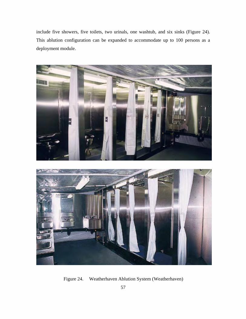
57
include five showers, five toilets, two urinals, one washtub, and six sinks (Figure 24).
This ablution configuration can be expanded to accommodate up to 100 persons as a
deployment module.
Figure 24. Weatherhaven Ablution System (Weatherhaven)

58
In 2011, Weatherhaven introduced its new shelter system. It includes the Tactical
Re-deployable Expanding Container Capability (TRECC-H) and (TRECC-V), which are
helicopter- and vehicle-based variants, respectively (Figure 25). When we first came
across the TRECC shelter system it was going through initial testing, it was referred to as
the SHARC (Specialized Helicopter and Aircraft Re-Deployable Container). The TRECC
was initially developed and designed for the NSHQ to meet its requirements for being
able to deploy from the inside of a CH-47 Chinook helicopter. The TRECC (Figure 25) is
constructed of lightweight aluminum and is deployable via air, road, rail, and sea, and it
fits within a 20-ft ISO container. It provides for a secure and weatherproof internal
payload capacity of 418 cu ft (11.8 m³) and has an internal load capacity of 6500 lb (2900
kg) for stowage of specialist equipment (Weatherhaven, Weatherhaven SHARC
Brochure).
Figure 25. Tactical Re-deployable Expanding Container Capability (TRECC) (Weatherhaven)
When the TRECC is full deployed and open it provides approximately 255 ft²
(23.7 m²) of working space with a ceiling of 8 ft (2.44m) (Figure 26). The TRECC can be

59
configured as required to include operations rooms, command posts, medical centers, and
specialist workshops (Weatherhaven, Weatherhaven SHARC Brochure).
Figure 26. Weatherhaven SHARC Fact Sheet (Weatherhaven SHARC Fact Sheet, 2011)
Figure 27. TRECC Being Loaded into the Back of a CH-47 (Weatherhaven)
60
G. MEDICAL FACILITIES
The next goal of our study was to find the right setup for an SOF medical unit.
We discovered a wide spectrum of options and varying viewpoints regarding the right
size and the required structure to treat troops in the field. For example, the Army uses
hard-sided (containerized) facilities for all of the surgery and clinical care in its combat
support hospitals (CSH), but it uses tents for wards and sleeping. The Air Force uses tents
from Alaska Structures for its Expeditionary Medical Facility (EMEDs) (Figure 28). The
Army also uses tents for its forward surgical teams (FSTs; A. Resnick, personal
communication, October 19, 2011).2 The four soft-sided shelter systems provided by
Alaska Structures, Base-X, DRASH, and Weatherhaven are all very similar and offer no
real distinctions beyond the features we discussed in the SUPCEN section of this report.
The question is what to use as a medical facility in a rapidly deployable camp?
2 This information came from our personal communications with Adam Resnick at the RAND
Corporation.

61
Figure 28. Soft sided Medical Facilities (DRASH and Alaska Structures)

62
H. OPTIONAL EQUIPMENT: BOBCAT
During this study, we looked at options for assisting in the setup and placement of
a camp and found a few commands were using compact skid loader-type equipment
(Figure 29) to assist in their operations. We contacted Bobcat Company for information
on their loaders. Bobcat is not the only manufacturer of skid loader equipment. There are
others (i.e., Caterpillar and John Deere) who also make good skid-steer loaders. But we
were not studying who makes the best skid loader; instead, our goal was to make general
suggestions on the capability available to units. We choose the skid-steer/compact track
loaders due to their performance, which was based on weight. The heavier the loader, the
better it performed, because the added weight and extra ground-to-surface contact (from
the track option and not the wheel option) increase the load capacity. The added loader
weight gives it better power and performance in difficult soil conditions, a benefit we
thought was important enough to go with a heavier option. The added size enables the
loader to push heavier loads in rough terrain, sandy surfaces, and muddy conditions. The
option we looked at was the Bobcat T770 Compact Track Loader; it was one of the
largest, but not the largest, option. We looked at its basic weight compared to its
operating capacity and found its ratio to be better than that of some of the higher end
models. The T770 comes with a 92 HP diesel engine, Rated Operating Capacity (ROC)
of 3,475 lb, strong lifting power (up to 11 ft of vertical lift) (Figure 30).
Figure 29. Bobcat T770 Compact Track Loader (Bobcat, 2011)

63
Figure 30. Bobcat T770 Compact Truck Loader Specifications (Bobcat, 2011)

64
I. OPCEN (OPERATIONS CENTER) COMMAND AND CONTROL CENTER SHELTERS: ALASKA STRUCTURES COMMAND AND CONTROL
Alaska Structures has a couple of different options for their Tactical Operations
Centers (TOCs), from their expeditionary command and control center unit which utilizes
the 18-ft wide or 20-ft wide Alaska Gable Shelters. They also have larger systems
available for division-sized TOCs or Joint Special Operational Task Force Headquarters
that offer over 10,000 sq ft of floor space (Figure 31). The tentage systems used for the
TOCs utilizes the same features as the life-support shelters. Shown in Figure 30, they are
soft-sided shelter systems that can expand out with corridors for the different departments
in the TOC. The system we observed was spacious, and it was easy to set up as an
effective command and control center. We highly recommend this system.
Figure 31. Alaska Structures Large TOC (Alaska Structures)
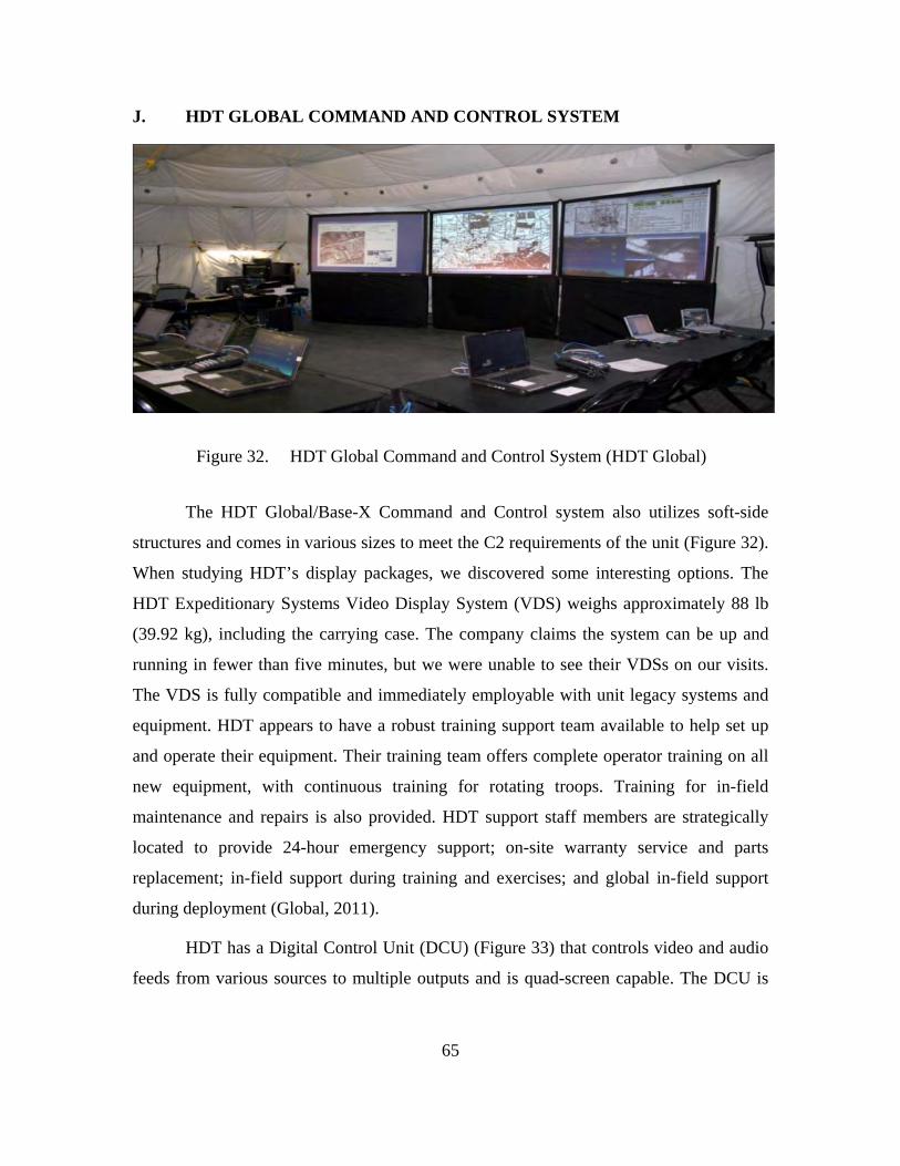
65
J. HDT GLOBAL COMMAND AND CONTROL SYSTEM
Figure 32. HDT Global Command and Control System (HDT Global)
The HDT Global/Base-X Command and Control system also utilizes soft-side
structures and comes in various sizes to meet the C2 requirements of the unit (Figure 32).
When studying HDT’s display packages, we discovered some interesting options. The
HDT Expeditionary Systems Video Display System (VDS) weighs approximately 88 lb
(39.92 kg), including the carrying case. The company claims the system can be up and
running in fewer than five minutes, but we were unable to see their VDSs on our visits.
The VDS is fully compatible and immediately employable with unit legacy systems and
equipment. HDT appears to have a robust training support team available to help set up
and operate their equipment. Their training team offers complete operator training on all
new equipment, with continuous training for rotating troops. Training for in-field
maintenance and repairs is also provided. HDT support staff members are strategically
located to provide 24-hour emergency support; on-site warranty service and parts
replacement; in-field support during training and exercises; and global in-field support
during deployment (Global, 2011).
HDT has a Digital Control Unit (DCU) (Figure 33) that controls video and audio
feeds from various sources to multiple outputs and is quad-screen capable. The DCU is

66
contained in a single shock-mounted transport case, complete with all cables and modules
to expand system capabilities. Components are customized to support specific mission
requirements (Global, HDT Global, 2011).
Figure 33. HDT Digital Control Unit (DCU) (HDT Global)
The HDT Video Display System uses a projector with the shortest throw in the
world. The free-standing screen and projector device are fewer than 26 in. (66 cm) apart.
The system is idea for smaller spaces as it takes up a lot less floor space than other video
systems and eliminates any sight-line obstruction in the field of view to the screen. The
system is lighter and faster to set up than traditional overhead frame systems. Another
nice feature is that the whole projector system can be set up in fewer than five minutes.
The VDS comes in two sizes, small and large.
HDT has another interesting product option available. Although this option is not
necessarily required, it could be useful. It is their Interactive Video Display System
(IVDS) (Figures 34 and 35), which allows the user to write and draw on the screen
surface, enabling digital capture of content from the screen to a computer.
DCU basic characteristics: •Video and audio run over CAT5/6 cable •Up to 32 inputs and 16 outputs over one system •Accessible control from any computer on your network •HTML interface requires no special software •Available touchscreen interface •Supports digital DVI and analog VGA •Dimensions 28.25 in. D x 29 in. W x 26.25 in. H 71.76 cm D x 73.66 cm W x 66.68 cm H •Weight 103 lb (46.72 kg)
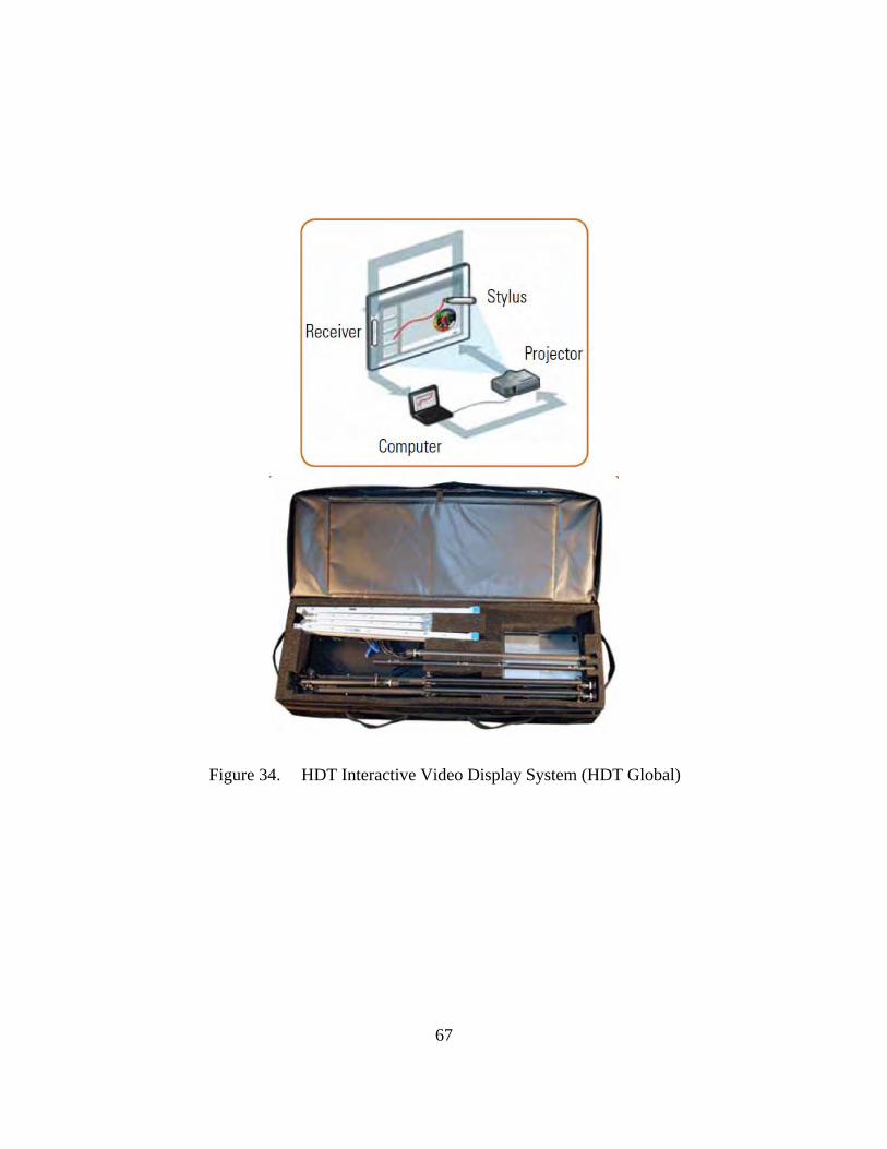
67
Figure 34. HDT Interactive Video Display System (HDT Global)

68
Figure 35. HDT Global VDS Fact Sheet (HDT Global)
HDT’s C2 chairs and tables (Figure 36) seem to be heavier than some of the other
manufacturers’, but they appear to be sturdier and more rugged. Each chair weighs 11.5
lb and can support up to 800 lb of distributed weight. They are made of hardened
polycarbonate plastic and 18-gauge oval steel tubing. For storage or transport, the chairs
are stacked four high (6-in. height) in a mildew-resistant storage bag. The HDT table
seems to be a rugged table with no special features, except that it comes with a cable
management bag that hangs over the end of the table for keeping the cables neat and
organized. The table was not pre wired.

69
Figure 36. HDT’s C2 Tables and Chairs
K. DRASH COMMAND AND CONTROL SYSTEM
The DRASH system (Figure 38), utilizes the same basic shelters used in their life
support system. Their command and control centers are widely used by the Army as part
of the Army’s Standard Integrated Command Post System (SICPS). The system
incorporates the Trailer Mounted Support System (TMSS) Medium and Large Systems
(Figure 37) which includes the shelter, power, environmental control and tactical
mobility which makes up the complete command operation center. One of the better
features we observed was a tactical platform system, which is a two-tier platform that
really enhanced the visibility and functionality for all of the users in the TOC. The
platform system we observed came from a company out of Vermont called Bike Track,
Inc. They also provided the hard flooring systems in the DRASH shelters we observed.
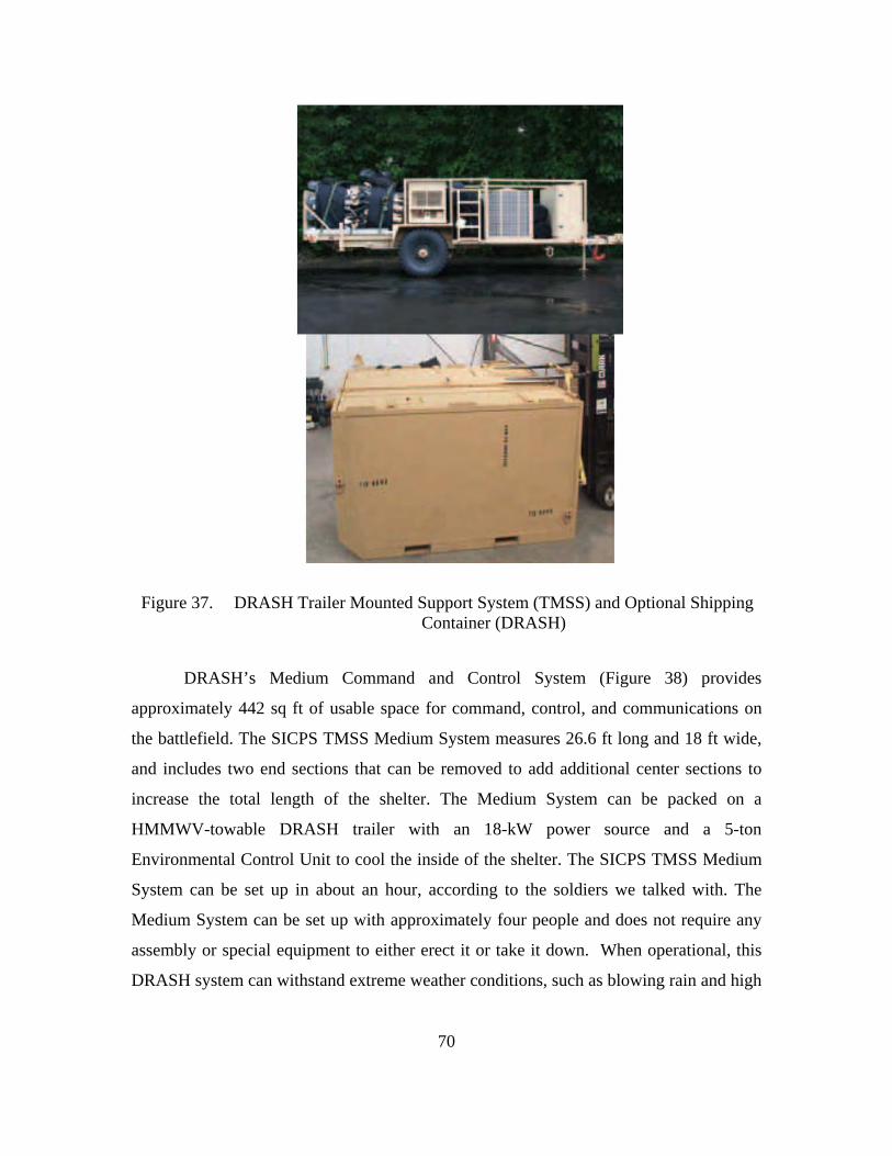
70
Figure 37. DRASH Trailer Mounted Support System (TMSS) and Optional Shipping Container (DRASH)
DRASH’s Medium Command and Control System (Figure 38) provides
approximately 442 sq ft of usable space for command, control, and communications on
the battlefield. The SICPS TMSS Medium System measures 26.6 ft long and 18 ft wide,
and includes two end sections that can be removed to add additional center sections to
increase the total length of the shelter. The Medium System can be packed on a
HMMWV-towable DRASH trailer with an 18-kW power source and a 5-ton
Environmental Control Unit to cool the inside of the shelter. The SICPS TMSS Medium
System can be set up in about an hour, according to the soldiers we talked with. The
Medium System can be set up with approximately four people and does not require any
assembly or special equipment to either erect it or take it down. When operational, this
DRASH system can withstand extreme weather conditions, such as blowing rain and high

71
wind. The SICPS TMSS Medium System can also sustain ambient temperatures of 40–
87 °F when subjected to extreme high and low temperature ranges of -50 to +131 °F
(DRASH, 2011).
Figure 38. DRASH Command and Control Center(DRASH)
The other option DRASH offers for a command and control system is the
DRASH Trailer Mounted Support System (TMSS) Large (Figure 39). With the TMSS
Large, the shelter system provides more than 1,120 sq ft of usable space for command,
control, and communications on the battlefield. The SICPS TMSS Large System
measures 51.4 ft long and 31.33 ft wide, and comes with either a regular end section or an
optional maintenance door. It is packed on to an FMTV-towable DRASH trailer with 33
kW of power and a 12-ton Environmental Control Unit to cool the inside of the shelter.
The trailer also provides the means to set up or take down the shelter via an inflatable air
bladder. To erect the shelter, the trailer is tilted so that the shelter can be positioned above
a low-pressure air blower and bladder, which pushes the shelter up from below. The

72
entire process takes approximately 45 minutes and requires a minimal number of
experienced personnel. Like the Medium, the SICPS TMSS Large is also operable in
extreme weather conditions, such as blowing rain and high wind. It is also able to sustain
ambient temperatures of +40–87 °F when subjected to extreme high and low temperature
ranges of -50 to +131 °F. DRASH’s SICPS TMSS Systems are currently being fielded to
all Army maneuver brigade combat teams, including units in Iraq and Afghanistan. This
system might be too large for a rapidly deployable SOF Headquarters, but could be a
viable option for an operation with less restrictive requirements.
Figure 39. DRASH Large Command and Control Center (DRASH)
L. THE WEATHERHAVEN COMMAND AND CONTROL SYSTEM
The only hard-sided shelter option we looked at is manufactured by
Weatherhaven. Other hard-sided options are available, but Weatherhaven’s shelter is
currently used by the NSHQ, which currently has nine MECCs in its inventory, and we
viewed interoperability and standardization as key factors. We looked at both the MECC
(Figure 40), for its compatibility, and the TRECC (Figures 41 and 42), because it was
specifically built to NSHQ specifications. The benefits of a hard-sided shelter are
obvious. Not only is the shelter itself ready to ship in its own container, but all of the
equipment that will be used in the command center is now also self-contained within the
container. The Weatherhaven hard-sided option is an expandable container shelter where

73
the sides fold down, making the container 1/3 the size of a standard command and control
trailer. It provides a living and working space that is three times larger than its shipping
footprint. In its packed configuration, the MECC (Figure 32) is a certified ISO container,
and nine units can be stacked on top of each other when outfitted with a steel core. With
the aluminum version of the MECC, three units can be stacked on top of each other. The
MECC can be transported anywhere in the world by road, rail, sea, or air.
Figure 40. Weatherhaven MECC (Weatherhaven)
One of the stated features of the Weatherhaven hard-sided structures includes the
ability to pre-wire and pre-plumb fixed mechanical and electrical systems, which helps
facilitate rapid on-site setup. The setup time varies, but the manufacturer states it takes
two experienced people 10–15 minutes to set up the MECC. A unit we visited that was
using the MECC stated that it took four to six people about an hour to build and complete
the system. The MECC comes in two standard sizes: 8-ft wide x 8-ft high x 20-ft long
and 8-ft wide x 8-ft, 6-in high x 20-ft long. The MECC is insulated for hot or cold
climates. The MECC allows various-sized interconnector kits and vestibules to be added
end-to-end and side-to-side to create larger complexes. The MECC can be set up on the
ground, linked to a vehicle, or mounted on a trailer. It can also be outfitted with collective
protection equipment when nuclear, biological, and chemical warfare are a threat.

74
Figure 41. Weatherhaven TRECC (Weatherhaven)
As we stated earlier, the internal equipment is stored and transported in the center
core of the MECC and TRECC, and this equipment does not need to be removed from
the unit for shipping; thus, sensitive electronic equipment is not exposed to the outside
elements. Weatherhaven allows for customizing electrical packages with outlets for
radios, computers, and other required equipment. Another nice feature of the MECC is
that, when space is an issue, it can be used with a stacking kit that allows the units to be
deployed on top of each other. The kit consists of a stairway with platform support, a
roof, and six extended wing supports.

75
Figure 42. Weatherhaven TRECC (Weatherhaven)
M. SPEC OPS, INC. (SOI)
The last company we looked at for the OPCEN piece was Spec Ops, Inc. (SOI).
They are a company out of Ashland, VA. They specialize in command and control
systems that range in size from two-person operators to brigade-level operations. They
have deployed over 30,000 products worldwide. Their customers include all branches of
the U.S. military, U.S. intelligence services, U.S. homeland security, and municipality-
level emergency responders. One of the SF units at Fort Bragg told us about SOI and how
good their equipment was. Unfortunately, we did not have time to visit them or a unit that
used their equipment; however, after researching their products, we felt it was important
to include them in our discussion of possible OPCEN solutions.
SOI currently offers over 100 commercially available command and control
products. They also design new systems based on customer-specific requirements. A few
of the items we looked into were their tactical displays. One of these displays is called
Megawall (Figure 43) and is a projector-based, soft-edged blended video display for
powerful, high resolution images. A single image from each projector is blended to create
one desktop background picture. Multiple display windows are then overlaid onto the
Megawall desktop, offering a robust, powerful command and control picture.
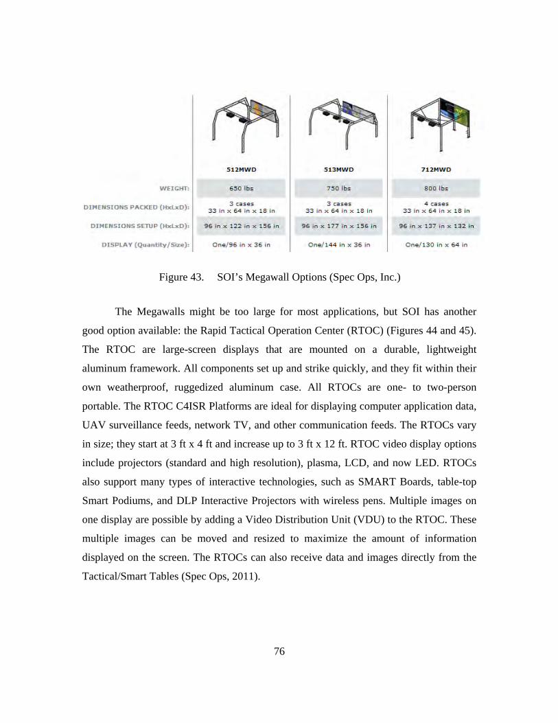
76
Figure 43. SOI’s Megawall Options (Spec Ops, Inc.)
The Megawalls might be too large for most applications, but SOI has another
good option available: the Rapid Tactical Operation Center (RTOC) (Figures 44 and 45).
The RTOC are large-screen displays that are mounted on a durable, lightweight
aluminum framework. All components set up and strike quickly, and they fit within their
own weatherproof, ruggedized aluminum case. All RTOCs are one- to two-person
portable. The RTOC C4ISR Platforms are ideal for displaying computer application data,
UAV surveillance feeds, network TV, and other communication feeds. The RTOCs vary
in size; they start at 3 ft x 4 ft and increase up to 3 ft x 12 ft. RTOC video display options
include projectors (standard and high resolution), plasma, LCD, and now LED. RTOCs
also support many types of interactive technologies, such as SMART Boards, table-top
Smart Podiums, and DLP Interactive Projectors with wireless pens. Multiple images on
one display are possible by adding a Video Distribution Unit (VDU) to the RTOC. These
multiple images can be moved and resized to maximize the amount of information
displayed on the screen. The RTOCs can also receive data and images directly from the
Tactical/Smart Tables (Spec Ops, 2011).

77
Figure 44. SOI’s Rapid Tactical Operation Center (RTOC) (Spec Ops, Inc.)
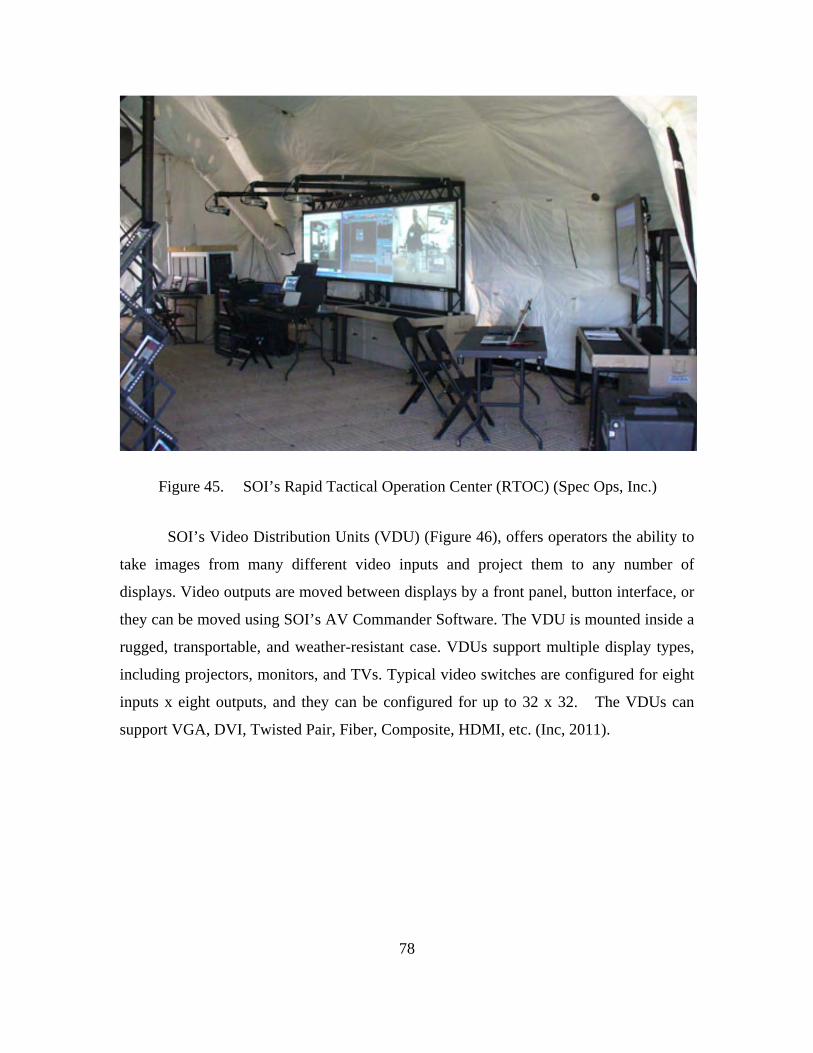
78
Figure 45. SOI’s Rapid Tactical Operation Center (RTOC) (Spec Ops, Inc.)
SOI’s Video Distribution Units (VDU) (Figure 46), offers operators the ability to
take images from many different video inputs and project them to any number of
displays. Video outputs are moved between displays by a front panel, button interface, or
they can be moved using SOI’s AV Commander Software. The VDU is mounted inside a
rugged, transportable, and weather-resistant case. VDUs support multiple display types,
including projectors, monitors, and TVs. Typical video switches are configured for eight
inputs x eight outputs, and they can be configured for up to 32 x 32. The VDUs can
support VGA, DVI, Twisted Pair, Fiber, Composite, HDMI, etc. (Inc, 2011).

79
Figure 46. SOI’s Video Distribution Units (VDU), (Spec Ops, Inc.)
SOI’s Tactical Smart Tables (Figure 47), seem to be some of the best options we
have come across. According to SOI’s website (SOI, 2011), these tables include the
following features:
Made from lightweight, rugged aluminum, all tables are prewired for power, secure and unsecure data, voice and video. Standard Tactical Tables offer two separate, switched GB networks channeled within the table. With pre-wiring and daisy-chain capabilities SOI's Tactical Tables significantly reduce cable management issues and control reconfiguration costs in both deployable and fixed TOCs/EOCs. SOI also offers Gigabit and managed switch upgrades for our installed base of tables. (Spec Ops I. , 2011)
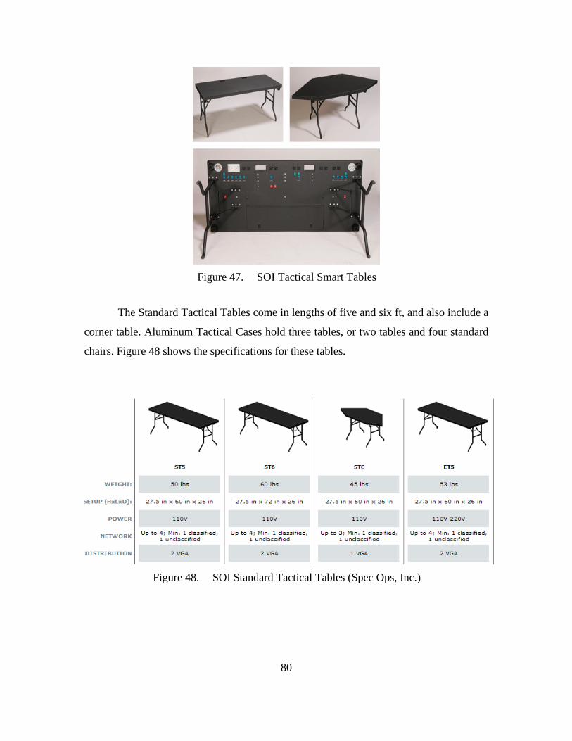
80
Figure 47. SOI Tactical Smart Tables
The Standard Tactical Tables come in lengths of five and six ft, and also include a
corner table. Aluminum Tactical Cases hold three tables, or two tables and four standard
chairs. Figure 48 shows the specifications for these tables.
Figure 48. SOI Standard Tactical Tables (Spec Ops, Inc.)

81
N. ALL-SOURCE CENTER (ASC): SOCC’S INTELLIGENCE FUSION CELL
Fusion of intelligence gathering and sharing across government agencies and
among allied nations has become a major priority. Strides to improve intelligence gaps
have been made since the beginning of the Global War on Terror. All U.S. SOF task
forces are implementing intelligence fusion cells, as seen in Figure 49, at the deployable
headquarters level.
Figure 49. All Source Center (ASC) (JP 2-0, Joint Intelligence, 2007)
Intelligence fusion is defined as:
The process of collecting and examining information from all available sources and intelligence disciplines (Figure 48 identifies these disciplines) to derive as complete an assessment as possible of detected activity. Intelligence fusion draws on the complementary strengths of all intelligence disciplines, and relies on an all-source approach to intelligence collection and analysis. Fusion relies on collection and analysis efforts that optimize the strengths and minimize the weaknesses of different intelligence disciplines. Information is sought from the widest possible range of sources to avoid any bias that can result from relying on a single source of information and to improve the accuracy and completeness of intelligence. The collection of information from multiple

82
sources is essential to countering the adversary’s operations security and deception operations. The operations of all collection sources must be synchronized and coordinated to allow cross-cueing and tip-off among collectors. All-source, fused intelligence results in a finished intelligence product that provides the most accurate and complete picture possible of what is known about an activity. While the level of detail in single-source reports may be sufficient to meet narrowly defined customer needs, fused reports are essential to gain an in-depth understanding. Because the adversary will engage in deception efforts, analysts should guard against placing unquestioned trust in a single-source intelligence report. (JP 2-0, Joint Intelligence, 2007)
Figure 50. Intelligence Disciplines, Subcategories, and Sources (JP 2-0, Joint Intelligence, 2007)

83
The ASC must be capable of managing large amounts of data. The requirements
of the data management for the ASC can be broken down into three basic areas or
categories: satellite communications (SATCOM) bandwidth, data storage, and
processing speed.
1. SATCOM Bandwidth
The ASC will be utilizing most of the Special Operations Command Component’s
(SOCC) bandwidth. The ASC’s bandwidth consumption includes the following
components:
1. Full-motion video (FMV) from the intelligence surveillance
reconnaissance (ISR) feeds;
2. High-resolution imagery files;
3. Large target intelligence package (TIP) files—usually containing large
images, more imagery, maps, video, etc.; and
Reach-back capability—communicating to host command, higher headquarters,
or larger intelligence fusion centers, which will allow the ability to communicate by voice
or post office protocol video teleconferencing (Pop-VTC), as well as transmitting large
data files that contain satellite imagery, HUMINT files, power, etc. This capability
requires significant amounts of bandwidth over a network.
The number of ISR assets, the size of the files transmitted, and the frequency of
transmission will drive the requirement for SATCOM bandwidth. Additionally, the way
in which operations are conducted can also drive SATCOM bandwidth requirements.
For example, if the SOCC must reach back for support in terms of satellite imagery,
target analysis, etc., then this may drive larger SATCOM bandwidth requirements than if
imagery was preloaded into computers or servers that are part of the organic SOCC
package that is fielded with the advance party.
NSHQ requires each Special Operation Task Group (SOTG) to be able to monitor
up to two ISR feeds at one time. NSHQ also requires that the SOCC is capable of
monitoring up to 12 ISR feeds at one time. As mentioned earlier, ISR feeds are one of

84
the largest consumers of SATCOM bandwidth. The SATCOM bandwidth must also
support the SOCC HQ (75–150 personnel) and six SOTG’s (30–60 personnel each).
NSHQ’s initial estimate of its SATCOM bandwidth requirement is for a meshed network
with a total of 38 Mbps over a joint operations area (JOA) and six Mbps dedicated for
reach back. Figure 51, illustrates this bandwidth estimate which includes four Mbps for
each SOTG (one Mbps for each of the two ISR feeds, two Mbps for PoP-VTC, voice
over internet protocol [VOIP], e-mail, and web); 14 Mbps for the SOCC (one Mbps for
each of the 12 ISR feeds; two Mbps for Pop-VTC, VOIP, e-mail, and web; two Mbps for
NSHQ reach back; and four Mbps for data traffic outside of the joint operations
agreement).
Figure 51. Estimated SATCOM Bandwidth Consumption. (Table built based on information provided by NSHQ)
SATCOM bandwidth is very expensive, and it is not getting any cheaper.
The U.S. Defense Department in recent months has seen price increases as great as 300 percent for commercial satellite communications. Military customers experienced ‘sticker shock’ as task orders for bandwidth and managed network services expired and were replaced with new orders—reflecting current market prices—awarded under the recently established Future Comsatcom Services Acquisition (FCSA) contract. (Brinton, 2011)
In our research, we found that bandwidth consumption is far more complex than
assigning a few Mbps here and there. Several variables determine bandwidth
consumption, such as the types of frequency bands, satellites, equipment, computer
0 5 10 15 20 25 30
ISR
VTC, VOIP, EMAIL, WEB
REACHBACK
NSHQ SOCC Core's Dedicated Bandwidth Consumption Rates
NSHQ SOCC Core's DedicatedBandwidth Consumption Rates

85
hardware and software, encryption, number of bits, etc. Many of these variables fall
outside the scope of our research. Because the ASC will be utilizing the majority of the
bandwidth, our goal is to identify the largest drivers of bandwidth, illustrated in Figure
52, and suggest some simple solutions to use the bandwidth more efficiently.
Figure 52. Typical Bandwidth Consumption Rates Spectrum. (Graph developed from information gathered from multiple sources)
To gain a better understanding of the factors that determine bandwidth usage, our
research team visited the following sites: Support Activity One (SUPACT 1), which is
Naval Special Warfare Group One’s (NSWG-1) intelligence ASC command and NSWG-
1’s mobile communication’s team (MCT). These units suggested two alternatives to cut
down on SATCOM bandwidth usage. The first, as we mentioned earlier, involves
preloading as much data (i.e., imagery, TIPs, etc.) pertaining to the area of operation
(AOR) as possible onto storable hard drives. Intelligence analysts require detailed
satellite imagery and pictures to conduct their analyses. The level of detail, the size of
the file, and the time it takes to send and receive the file on a network are correlated.
Preloading as much satellite imagery and pictures will save time and bandwidth
consumption. The second alternative is to utilize the global broadcast service (GBS).
0 2 4 6 8 10 12
Phone calls
Video calling
VTC (3 locations)
VTC (5 locations)
VTC (7+ locations)
UAV FEED
Bandwidth (Mbps) Minimum
Bandwidth (Mbps)Recommended

86
The GBS leverages commercial direct broadcast satellite technology to deliver critical
information to the nation's warfighters (Raytheon, 2011). It will eat up less bandwidth
because it acts as what could be termed, “DirectTV for the warfighter,” in that it is a
receive-only technology that streams data and video through your broadband
communications link, but at a smaller fraction of bandwidth because you do not need the
same amount of bandwidth to transmit and receive. GBS offers a DoD wideband asset
that provides both classified and unclassified high data rate, direct broadcast to military
members worldwide. NATO is also planning to launch a Satellite Broadcast Service
(SBS) as a counterpart to the U.S. Global Broadcast Service (NATO, 2003).
Windmill International, Inc. provides commercial off-the-shelf GBS packages that
would be ideal for NSHQ. Table 2 illustrates the pricing packages that Windmill has to
offer.
The system is made up of two key components, the Receive Terminal (RT) and the Receive Broadcast Manager (RBM). The Receive Terminal includes the antenna/positioner, integral Integrated Receiver Decoder, an accessory kit for the RT, shipped in a hard-sided airline rolling bag suitable for checked baggage. The RBM consists of a PC, standard windows software, FazzT software, and interconnect and power supply cables. This is shipped in a hard-sided rolling case suitable for airline carry-on. Total system weight in the cases is 78lbs. The system is designed to be hand carried – the RT can be carried over-the-shoulder or by hand and outside its transit case it meets airline carryon luggage requirements. The PC, and any needed cables, can be carried separately in a standard briefcase or computer bag. Total system weight in this hand-carry configuration is approximately 31 pounds. (www.windmill-intl.com)

87
Table 2. Commercial Pricing for Windmill GBS. (www.windmill-intl.com)
2. Data Storage
Table 3. Imagery File Size Spectrum(satimagingcorp.com)
Large volumes of data storage are necessary to house the working and reference
files necessary to support operations. Table 3 shows the many variables and the wide
spectrum in imagery file size. As an illustration, if a mission requires 10 images and each
image averages 800 MB, then data storage for satellite imagery alone will require 8 GB

88
of space. In addition to storage for imagery, HUMINT operations require large volumes
of data storage for various file types (i.e., images, text, audio, and video) for one
particular source or target; such files can require gigabytes of storage space. In addition,
working files need to be stored on site, and these also include image files, large
databases, text and rich text format, briefings, audio, and video. All of these different
capabilities, taken together, require several terabytes of storage. We realize that as data
compression technology becomes better and more available, storage requirements could
go down. However, our experience has shown that as more new technologies are fielded
on the battlefield, such as Lighthouse3 and the Biometric Analysis Tracking System
(BATS)4 (Figure 53), other intelligence gathering and analysis tools and data, etc., the
demand for storage is more likely to increase than to decrease. Further, data storage
technologies are becoming cheaper and smaller every day.
3 Lighthouse is a revolutionary technology innovation system for smart phones, capable of quickly
mapping elements in the human terrain, such as tribes, family, links, livelihood, basic necessities consumption, and customs.
4 The Biometric Analysis Tracking System uses thumbprints and facial and retinal scans to identify foreign persons of interest to human intelligence and counterintelligence personnel.

89
Figure 53. The Biometric Analysis Tracking System, left (JP 2-0, Joint Intelligence, 2007) and Lighthouse Main Menu, right. (Image provided by Naval Post
Graduate School Core Lab)
3. Processing Speed
Processing speed is critical for operating large database programs that include
social network analysis software such as Palantir5 (Figure 54) which manipulate large
5 “Palantir empowers decision-makers at every level by providing them with a robust analytics
platform that displays, organizes, stores, and analyzes the complex fabric of friendly, threat, neutral and clandestine human terrain in a multi-dimensional environment.
1. Save thousands of man hours. Palantir allows you to see all of your data, from many systems, in a single place and automates hundreds of tasks that analysts currently do manually. Search through all your data at high speed to pull out significant intelligence.
2. Palantir’s power allows organizations to make discoveries that would otherwise be impossible to make even with 10x the manpower. Palantir’s advanced analytical functionality not only reveals important connections, but allows users to share in real time so that a unit’s discovery is automatically shared with the larger organization and stored for future retrieval.
Units obtain the intelligence they need immediately, instead of waiting for it to be disseminated down (automatically controlled to their authorization and clearance level). Democratized intelligence makes the whole organization smarter and more effective.” (palantirtech.com/government/defense)

90
databases and other files to rapidly analyze tactical information obtained from the
battlefield so that the information and knowledge may be utilized for follow-on missions
and targets. The ability to do this better and faster than the enemy is what provides the
SOCC with its ability to establish and maintain intelligence dominance. Therefore,
purchasing machines with the highest processing speeds, dictated by the latest
technology, is highly recommended.
Figure 54. Images from Palantir Intelligence Analysis Software (palantirtech.com/government/defense)
O. THE BATTLEFIELD INFORMATION COLLECTION AND EXPLOITATION SYSTEMS (BICES)
BICES is the U.S.’s designated system for intelligence sharing with NATO and
the NATO member nations. The diagram in Figure 54 illustrates how BICES operations
are centered at RAF Molesworth, UK (Joint Analysis Center) and are extended to Kabul,
Tampa, Hawaii, and Washington, D.C. U.S. BICES provides NATO Secret with
connectivity to all U.S. Combatant Commands (COCOMs), Services, and many agencies.
The U.S. BICES framework (services and capabilities) acts as an extension to all the
COCOMs. In addition, there is heavy NATO usage of BICES, because several non-
NATO nations make use of it to share information with NATO nations and to obtain
releasable information. In addition to access to nationally released intelligence products,
BICES provides intelligence tools that can be used for analysis and operations planning.

91
Figure 55. BICES Network Diagram (Diagram provided by SOCOM)
BICES provides NATO Secret with the ability to communicate with BICES
member nations and NATO using secure e-mail, secure voice and VTC (via VOIP Face
Phone), and shared early warning of Tactical Ballistic Missile (TBM) launches. The
services that U.S. BICES provides are a metadata tagged product database (finished and
tear line); an Imagery Product Library (IPL); GCCSI3; Harmony; Google Earth; FMV via
PSDS2; CIDNE; and secure social networking. BICES provides access to operational
tools to support strategic, operational, and tactical communications requirements (Figures
55 and 56). BICES is currently being utilized by NSHQ and its SOTGs in Afghanistan
(Figure 57).

92
Figure 56. NSHQ SOCC Concept for BICES (Diagram provided by NSHQ)

93
Figure 57. BICES Currently Being Used in Afghanistan (Diagram provided by NSHQ)
P. SIGNAL CENTER (SIGCEN)
SDN-Lite(vx) (Figure 58), is a deployable secure satellite communication system
that provides secure voice, video, and data via a lightweight, commercial air transportable
kit. The SDN-L(vx) provides high-capacity BLACK voice/data and RED
voice/data/video to small SOF teams (four to eight personnel) operating self-sufficiently
at remote locations. The SDN-L(vx) provides essential communication capability for
situational awareness, mission planning, analysis, collaboration, and real-time mission
coordination for SOF teams. It provides deployed SOF teams seamless interaction with
their respective theater; the United States Special Operations Command (USSOCOM);
the Department of Defense (DoD); and any national-level command, control,
communications, computers, and intelligence (C4I) systems during short-term
deployments or during the initial phases of an operation when no other in-theater, secure,
tactical C4I structure exists.

94
Figure 58. Special Operations Forces Deployable Node Lite(vx) [SDN-L(vx)] (Image provided by SOCOM)
The USSOCOM has developed and fielded the SDN-L(vx), and tailored it to the
C4I requirements of the tactical SOF community. The concept of the SDN-L(vx) (Figure
59) is to provide high bandwidth network-centric communications capability in a very
small package that requires minimal specialized operator training. The SDN-L(vx)
package will be ideal for a small advanced liaison (ADVON) and liaison elements that
will be representing NSHQ throughout the AOR.

95
Figure 59. SDN-L(vx) Systems Capabilities Diagram (Image provided by SOCOM)
SDN-Medium (SDN-M) is a deployable, lightweight, commercial air
transportable, secure satellite communications system that provides secure voice, video,
and data services. The SDN-M (Figure 60), includes everything in the SDN-L (vx) plus
additional equipment that provides deployed SOF with a first-in, robust C4I capability. It
ensures deployed SOF seamless interaction with their respective theater, the USSOCOM,
the DoD, and any national-level C4I systems during short-term deployments or during
the initial phases of an operation when no other in-theater, secure, tactical C4I
infrastructure exists. In prolonged, large-scale operations, sustained C4I support can be
provided by theater communications assets with the SDN-M being used in an
augmentation or supporting role.

96
Figure 60. Special Operations Forces Deployable Node Medium (SDN-M) (Image provided by SOCOM)
USSOCOM has developed and fielded the SDN-M to meet the C4I requirements
of the tactical SOF community. The concept of operations, illustrated in Figure 61, is
simple: Enable a deployed SOF team of 10–15 personnel with the ability to access the
same sensitive compartmented information (SCI), collateral, and unclassified C4I
services that are available to them in garrison (via SOF tactical gateways), from deployed
locations around the world. The SDN-M package will be ideal for the initial 70 man core
element that will deploy during the first phase.

97
Figure 61. SDN-M Systems Capabilities Diagram (Image provided by SOCOM)
The SDN-H, (Figure 62), provides a deployed SOF Headquarters with a first-in,
robust C4I capability. It ensures deployed SOF seamless interaction with their respective
theater, the USSOCOM, the DoD, and any national C4I systems during short-term
deployments or during the initial phases of a long-term operation when no other in-
theater, secure, tactical C4I infrastructure exists. In prolonged, large-scale operations,
sustained C4I support will be provided by theater communications assets, with the SDN-
H being used in an augmentation or supporting role.

98
Figure 62. Special Operations Forces Deployable Node Heavy (SDN-H) (Image provided by SOCOM)
The SDN-H concept of operations is simple: Enable the deployed SOF
commander [for example, the commander of the Joint Special Operations Task Force
(JSOTF)] and his staff with the ability to access the SCI, collateral, and unclassified C4I
services that are available to them in garrison, from deployed locations around the world
as illustrated in Figure 63. The SDN-H is ideal for the SOCC Core at its full operational
capacity.
Figure 63. SDN-H Systems Capabilities Diagram (Image provided by SOCOM)

99
In this section, we introduce the concept of light, medium, and heavy. Different
organizations may have different definitions of these terms, but we present ours in order
to create a common language for our discussion of these terms in this thesis. Table 4
describes the capabilities, Table 5 lists the major pieces of hardware, and Table 6
estimates the package costs of each of these three levels.
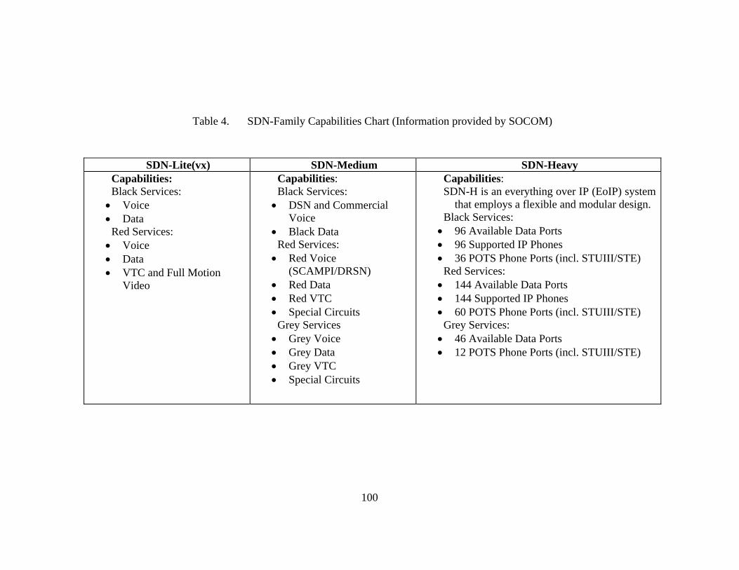
100
Table 4. SDN-Family Capabilities Chart (Information provided by SOCOM)
SDN-Lite(vx) SDN-Medium SDN-Heavy Capabilities: Black Services: Voice Data Red Services: Voice Data VTC and Full Motion
Video
Capabilities: Black Services: DSN and Commercial
Voice Black Data Red Services: Red Voice
(SCAMPI/DRSN) Red Data Red VTC Special Circuits Grey Services Grey Voice Grey Data Grey VTC Special Circuits
Capabilities: SDN-H is an everything over IP (EoIP) system
that employs a flexible and modular design. Black Services: 96 Available Data Ports 96 Supported IP Phones 36 POTS Phone Ports (incl. STUIII/STE) Red Services: 144 Available Data Ports 144 Supported IP Phones 60 POTS Phone Ports (incl. STUIII/STE) Grey Services: 46 Available Data Ports 12 POTS Phone Ports (incl. STUIII/STE)

101
Table 5. SDN-Family Major Pieces of Hardware Chart (Provided by SOCOM)
SDN-Lite(vx) SDN-Medium SDN-Heavy Major pieces of hardware: VSAT: 0.9M VSAT iDirect Evolution Modem 700 BRX UPS Black Baseband: Cisco 1812 Router FIPS 140-2 certified 6 Port switch with PoE Power conditioner Power backup 4 conditioned AC outputs Red Baseband: SecNet 54 Klas 2150 8 Ports; with 1 w/PoE Integrated power backup Devices: CF-19 Laptop CF-52 Laptop Cisco 7941 IP phone
Major pieces of hardware: 1.0M Hawkeye Lite Ku-Band auto
acquire SATCOM terminal Everything included in the SDN-L
(vx) plus the following additional equipment:
COTS Equipment CISCO Routers Multi-VLAN Switches 8-Port Switches Laptop Computers Cisco/Avaya IP Telephones VoIP Soft Telephones Flatbed Scanner Projector Desktop Cameras Headsets Color Printers KG-250 xPEP
Major pieces of hardware: DMSC 2.4M Deployable Tri-
Band or Quad-Band SATCOM Terminal
Everything included in the SDN-
M plus the following additional equipment:
Black and Red Baseband
Modules (BBM) ViaSat KG-250 HAIPE
Encryptor ViaSat xPEP TCP Accelerator Cisco 3825 Router Net VX900t Voice Accelerator BlackBox VDSL Wire
Modems Grey Baseband Module (BBM) ViaSat KG-250 HAIPE
Encryptor ViaSat xPEP TCP Accelerator Cisco 3825 Router BlackBox VDSL Wire
Modems Uninterruptible Power Supply

102
(UPS) 1500VA UPS Local Expansion Module (LEM) Cisco Catalyst 3560 Switch Cisco VG224 Analog Phone
Gateway BlackBox VDSL Wire Modem 1000VA UPS Call Manager Module (CMM) Cisco 7825 Call Managers
with CM

103
Table 6. SDN-Family Estimated Cost (Provided by SOCOM)
SDN-Lite(vx) SDN-Medium SDN-Heavy Cost: $220 thousand each
Cost: $400 thousand each
Cost: $2.2 Million (comes with complete
TACLAN suite)

104
In addition to the SDN packages, the U.S. SOF units supplement their
communications with a TACLAN suite. Each TACLAN suite, illustrated in Figure 64,
consists of three easily transportable, multiple-integrated networks; 60 general use
laptops; and 10 intelligence laptops. A TACLAN network contains commercial servers,
routers, and hubs, which can operate at user-selectable classification levels [e.g.,
unclassified, collateral, coalition, or sensitive compartmented information (SCI)
networks]. A TACLAN suite will allow SOCC to create its own domain. It includes
three large racks of servers, 70 computers, and its own UPS. The TACLAN holds a huge
amount of storage, runs its own e-mail exchange, and can be remotely accessed. The
TACLAN suite provides a package of independence and an abundance of storage.
Figure 64. Tactical Local Area Network (TACLAN) (Image provided by SOCOM)
SDN-Lite(vx) packages can be used for liaisons who represent the SOCC and
allow them to travel with a small portable communications package that gives them
compatible/interoperable communication equipment so they can send and receive
information. Secure iridium satellite phones (Figure 65), can be a cheaper alternative for
this task. As their last resort communication alternative, all U.S. SOF units use iridium
satellite phones. These phones will be a necessity at the SOCCs and SOTGs. They cost
$1,500 for unsecure phones and $3,000 for the secure iridium satellite phones.

105
Figure 65. Iridium Phones (Image from iridium.com)
All the SOF units that our research team visited concur with a phased-in approach
as a solution for a signal and communications infrastructure. This entails purchasing a
SDM-H that comes with a TACLAN, an SDN-M, and a GBS suite for the SOCC Core
headquarters. The SDN-M, GBS, and TACLAN will deploy with the 70 man core during
the first phase. The TACLAN and GBS can supplement the SDN-M to make a more
robust package that will increase its capabilities. The SDN-H will arrive with the main
body during the second phase. The SDN-H will take the place of the SDN-M as the
primary communications platform and the SDN-M will be used as back-up for the high
priority users. The SOCC Core will also deploy with at least two SDN-L (vx) and three
iridium phones. Additionally, each SOTG will deploy with a SDN-M, GBS suite, and an
iridium phone. The total cost for this SIGCEN is estimated at $6.5 million (Table 7).

106
Table 7. Total Cost of SIGCEN
Item Quantity Unit Cost Total Cost
SDN-H 1 $2,200,000 $2,200,000
SDN-M 7 $400,000 $2,800,000
SDN-L (vx) 2 $220,000 $440,000
GBS SUITE 7 $128,529 $899,703
GBS Support 7 $9,950 $69,650
GBS Training 1 $23,750 $23,750
Iridium Phone 9 $3,000 $27,000
Total Basic Cost of SIGCEN= $6,460,103.00

107
VI. RECOMMENDATIONS
In developing our conclusions for the SUPCEN, we considered the following
factors: weight, size, costs, ease of setup, durability, transportability, environmental
factors, and function. All of the manufacturers we compared surpassed the minimum
requirements and standards we received from the NSHQ’s J4. As we stated earlier, there
are other manufacturers of military camps, but these four companies were most often
recommended to our team during our initial meetings with several operational military
units. As our data shows (Table 8), Alaska Structures came out on top in almost every
category. We used three measuring criteria for our table: exceed requirements (), met
requirements ( ), met requirements / substandard (). In our study, Exceed
Requirements meant the manufacture was well above the minimum requirements we
received from the NSHQ or the feedback we received from the various units was well
above average. Met Requirements meant the manufacture met all of the minimum
requirements we received from the NSHQ and the feedback from the units in the field
were either neutral or had a mix of both positive and negative comments. Met
Requirements /Substandard meant that the manufacturer met all of the NSHQ
requirements but most of the feedback from the units in the field were negative. In the
following section, we briefly cover each manufacturer and discuss some of the bigger
factors that led to our conclusions.
When we started the camp study, we initially wanted to analyze each
manufacturer’s shelters, generators, and ablutions. We studied the shelters and ablutions
in great detail, but, when it came to generators, we found that the commands and units
were looking for smaller generators. Most of the units we talked to could not tell us who
manufactured their generator or where it came from. Most of the units did not care who
manufactured the generators; instead, what they wanted was smaller generators. For
example, for the soft-sided shelter systems (AKS, Base–X, and DRASH), users preferred
the 35 kW generators over the 60 kW generators that are standard for most camps. With
the Weatherhaven systems, users wanted a smaller generator than the current 35 kW
generator, which is standard for this system; the noise was the primary reason. Users
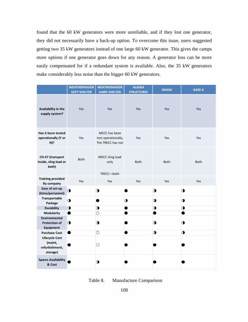
108
found that the 60 kW generators were more unreliable, and if they lost one generator,
they did not necessarily have a back-up option. To overcome this issue, users suggested
getting two 35 kW generators instead of one large 60 kW generator. This gives the camps
more options if one generator goes down for any reason. A generator loss can be more
easily compensated for if a redundant system is available. Also, the 35 kW generators
make considerably less noise than the bigger 60 kW generators.
Table 8. Manufacture Comparison
WEATHERHAVEN
SOFT SHELTER
WEATHERHAVEN
HARD SHELTER
ALASKA
STRUCTURESDRASH BASE‐X
Yes Yes Yes Yes Yes
Has it been tested
operationally (Y or
N)?
Yes
MECC has been
test operationally,
The TRECC has not
Yes Yes Yes
BothMECC sling load
only
TRECC—both
Training provided
By companyYes Yes Yes Yes Yes
Ease of set‐up
(time/personnel)2 2 3 2 2
Transportable
Package2 3 2 2 2
Durability 2 2 3 2 2
Modularity 3 1 3 3 3
Environmental
Protection of
Equipment
2 2 3 2 2
Purchase Cost 3 1 3 2 2
Lifecycle Cost
(maint,
refurbishment,
storage)
3 1 3 3 3
Spares Availability
& Cost3 2 3 3 3
Availability in the
supply system?
CH‐47 (transport
inside, sling load or
both)
Both Both Both

109
As we studied each manufacturer, we discovered that each was very good in the
areas of training, transportation/shipping, and spare parts availability. Most of their
customer service departments’ promise 24/7 customer service availability. In the rest of
this section, we break down several of the differences in these manufactures. When it
came to transportation, we assumed the camp would have a HUMVV-type vehicle
available for transporting some of the equipment for the last mile. As a result, we found
several of the solutions we examined, particularly the HDT Global and DRASH systems
that are set up on trailers, to be useful and effective.
One of the problems we heard from users in the field regarding HDT’s Base-X
was that this system’s frames are not as rugged and sturdy as Alaska Structure's frames.
We were told the plastic and aluminum framing breaks. In addition, these systems have a
field life of three years, while the Alaska Structures and DRASH systems have a field life
of five years. We had problems gathering all of the cost data from HDT Global, the
manufacturer of Base-X; they were reluctant to share their cost data with us, even after
we had contacted them several times, so we could not do a good cost comparison against
the other manufacturers. We really liked Base-X’s alternative energy equipment. No
other manufacturer came close to the equipment that HDT Global had available in the
field. Their equipment was revolutionary, and we highly recommend looking into HDT
Global’s alternative energy equipment for any power requirements solution. Users with
available alternative energy solutions were not as worried about the supply convoys
making it to their camp, because they knew they had electric power available to them via
the solar power they used in camp.
With the DRASH systems, we liked the M Series shelters for their overall size
and for the convenience of shipping on DRASH’s Trailer Mounted Support System
(TMSS). Traditional DRASH systems are fitted on trailers and are convenient for a
rapidly deployable DRASH. DRASH’s trailer system was done well and liked by their
users. However, the shelter system itself was not rated as highly as the Alaska Structures
and Base–X shelters. Several users had switched over to Base-X and Alaska Structures
for their shelter systems, and they preferred these shelters due to their durability, ease of
setup, and comfort. The DRASH representatives were very helpful in gathering

110
information, and they provided great customer support when we were working toward a
solution. Several units in the Army and Marines use DRASH and are happy with their
shelters.
Weatherhaven had some of the most deluxe camp solutions we came across and
their products were exceptional. Their hard-sided shelters, the MECC and TRECC, truly
show the convenience of a shelter system that is ready for rapid deployment and
transportation. It is the convenience of having the shelter basically in a shipping container
and ready to move. One of the issues we saw, but were unable to verify, related to the
mobility of the MECC and the TRECC on sandy or soft ground terrain, or in a snow
environment. The shelters move easily on firm, hard surfaces, but deploying them to an
unknown area, where the terrain could easily change from mission to mission, could
drastically affect the camp’s ability to move to a more suitable place, which is a big
concern. Weatherhaven’s hard-sided shelters were very dependent upon deploying to an
area with perfect conditions. In terms of the transportation of the SOCC, we were initially
designing for a camp that could be internally loaded into a CH-47 “Chinook” helicopter.
We visited a CH-47 squadron in Stockton, CA, that had supported Special Operations
missions during Operation Enduring Freedom, and these aircrew members stated they
preferred a tandem load underneath the helicopter (Figure 67), rather than an internal load
(Figure 68). Several factors went into that recommendation, with increased safety being
the first and most important. The aircrews (loadmasters) must be able to walk around the
aircraft to perform visual checks outside the aircraft, while reporting continuous updates
to the pilots throughout the flight/sortie. These safety checks are particularly important
during landings and movement close to the ground, especially while operating in hostile
environments. We gave the aircrew the dimensions of the TRECC, and they commented
that it would be difficult to perform their safety checks with a large item, such as a
TRECC, inside. Although it would not be impossible, they would rather tandem sling
load the TRECC, if they had a choice. They preferred a tandem sling load to a single
sling load (Figure 66). The aircrews can drop off a sling-loaded item quickly, safely, and
accurately (inside of a parking space), which results in less time spent in the operating
area. The crew lands to drop off personnel and any internally loaded equipment.

111
Figure 66. CH-47 Single Sling Load

112
Figure 67. CH-47 Tandem Sling Load (Images, 2011)
Figure 68. CH-47 Internal Load with TRECC (Weatherhaven)
113
Another issue we heard about from one of the users was the ability to keep the
elements out of the Weatherhaven shelter. This issue affected the shelter’s poor durability
rating. The user told us that his unit encountered several leaks in their MECC and that
mice had gotten into the wiring bundles under the MECC floors, because they were
unable to seal off those areas. We spoke with Weatherhaven’s representatives about this
issue, and they said that they had addressed it, and it was fixed.
We also scored the MECC poorly in the life cycle cost area, because a user told us
that the MECC had to go back to the manufacturer for upgrades and overhaul after 18
months, if exposed to the elements, and after 24 months, if it was under cover in theater.
Each shelter costs an average of approximately $17,500 to repair. One of the users
MECCs had to go back to the manufacturer for upgrades and modifications totaling
approximately $70,000. Granted, it could be argued that the command asked for the
upgrades to their MECC, and that these were the initial MECCs so Weatherhaven has
now incorporated the lessons learned into its current MECC design. However, we are
concerned because, instead of just one component having to be sent in, the entire unit had
to be sent in, thus increasing the total cost of maintaining the system over the whole life
of the shelter.
The cost for the Weatherhaven solution was more than double the cost for the
Alaska Structures solution. The cost could be better managed if Weatherhaven scaled
back some of the MECCs that were slated for the ablutions. Each ablution cost $275,000,
and a 150-person camp would require four MECCs to meet the camp requirements.
Choosing a soft-side shelter in that area alone would not only save over $1 million, but
would also eliminate three sorties in getting these ablution facilities into the theater. We
understand how nice the Weatherhaven MECC and TRECC are, but at that cost of
luxury, our team did not see the cost benefit in going with the Weatherhaven solution. By
eliminating the requirement for internally carrying the TRECC, we reduced the sortie
requirements for a CH-47 helicopter from 40 to 31 and from 36 to 31, if the sorties
combined the troop movement of 150 troops with moving the camp into theater.
We chose Alaska Structures for multiple reasons, but one of the biggest reasons
was our observations of these shelters in the field. They were of the best quality

114
compared to the other systems evaluated and their ease of operation was high. The units
we visited also had high praise for Alaska Structures’ products. Numerous SOCOM units
in the U. S. currently use Alaska Structures as their camp of choice. We did not select
them for that reason alone. We considered several other factors, but we felt that it was
important to mention that some of the leading SF units in the entire world use Alaska
Structures’ products: We wanted to find out why, and we did.
Several users said Alaska Structures were the easiest to set up and tear down, and
most of the users we visited used multiple manufacturers’ products for their camps. In
fact, when that was the case, Alaska Structures was always the recommended
manufacturer. A few of the other manufacturers’ frames did not go up as easily and as
quickly as the company stated.
Alaska Structures also surpassed the other manufacturers in the area of
environmental conditions. Their shelters far exceeded our minimum requirements. For
example, Alaska Structures’ gable roof system shelter can handle snow loads of up to 125
lb/sq ft (56.7 kg/m2; and it tested successfully for wind loads of up to 120 mph (193
km/h). The AKSS was tested to successfully withstand wind loads of 70 mph (112.7
km/h) with gusts of 80 mph (128.75 km/h) Tests also showed that it can handle
successfully a snow load of 20 lb/sq ft (9 kg; PSF) Structures, Alaska Structures, 2011).
Our minimum requirements were as follows:
1. Withstand snow loads of 10 lb (5 kg) per sq ft.(m) for 12 hours without
damage to the frame or structure
2. Withstand wind loads of 55 mph (89 km/h), with gusts up to 65 mph (105
km/h)
All of the shelters performed equally well in the area of temperature control and
were operational from -20–120 °F (-29–49 °C).
Our final comparison point was cost data. In Table 9 our cost data includes all of
the shelters, ablutions, and generators for the SUPCEN piece of the camp. We were given

115
very “close estimates” from all of the manufacturers we studied, except for HDT Global’s
Base-X camp. We made several attempts to gather this data from multiple sources, but
were unable to get the data from them.
Manufacturer Cost Required Number of 20-
ft Shipping Containers
Alaska Structures $2.8 M 276
DRASH $2.9M 177
Weatherhaven $5.9M 318
Table 9. Shipping and Cost Comparison Table9
Our comparison of all of the data and parameters set forth in this study shows that
Alaska Structures is the best option. Figure 70 shows how each manufacturer ranked on a
scale of 1–5, with 1 being the poorest result and 5 being the highest. Each manufacturer
had the best product in at least one area; however, when all the factors were considered as
a whole, Alaska Structures came out on top, and we would recommend it for use by any
military force looking to assemble a rapidly deployable camp anywhere around the
world. Our final solution is depicted in the drawing below from Alaska Structure of the
150-person SOCC camp (Figure 69).
6 The shipping data was received from Alaska Structures Engineering Department.
7 The Shipping data was received from DRASH Sales representative as an estimate.
8 The shipping data was based off inputs received from Weatherhaven on an 84 man camp set-up. We multiplied the life support areas of the camp by a factor of 1.5 to get an estimate on shipping.
9 The data we received for this table were obtained from the manufactures. These cost were approximations and were not actually quoted in a request for proposal.

116
Figure 69. Alaska Structures 150 Camp Drawing (Alaska Structure, personal communication, November 11, 201110)
10 We received permission from Alaska Structures to use the camp diagram via an e-mail dated
November 11, 2011.

117
Figure 70. Major Decision Factors
In Figure 70 we present six of the major decision factors we took into account
with this study. The first factor was the user recommendations we received from each of
the units we visited. We measured everything on a scale of 1–5. In the user
recommendations area, a 5 indicated that the users had no complaints and would
recommend the product to another user. A score of 1 meant none of the users liked the
product and would not recommend this manufacturer’s camp. With the cost data, we gave
a product a 5 if it was very cost effective and a 1 if it was not very cost effective. In the
1 2 3 4 5
Weatherhaven
DRASH
Base‐X
AlaskaStructures
UserRecommendation
Cost
EnviromentalConditionPerformance
Durability
Weight/Size
EasyofSet‐up

118
environmental conditions and performance area, we based the scoring criteria on
published testing conducted on each camp, with a score of 5 indicating that the camp far
exceeded the requirements and a 1 indicating that the camp did not meet the established
requirements. With durability, we took into account not only published life expectancies,
but also reports from users on how well a particular shelter performed under field
conditions. A 5 meant well above average durability, and a 1 meant well below average
durability. With weight and size, we looked at the ability to minimize and condense the
camp for transportation: A 5 represented a small shipping footprint, and a 1 represented a
very large shipping footprint. Our final criterion was ease of the setup, which included
the time required to build the camp, as well as the equipment required to set up the camp.
A 5 represented minimal time and tools required to set up the camp, and a 1 represented a
long and difficult setup time and the requirement for outside tools and equipment to build
the camp.
A required piece of special equipment is the skid loader. It is useful when setting
up and tearing down the camp and is capable of handling many of the situations/issues
encountered while operating a forward-deployed operational camp.
For the medical solution of this rapidly deployable camp, several good soft-sided
shelter options were available by all of the manufacturers and were equally good at
meeting general medical care requirements. But if the medical care requires a hard- sided
shelter, the TRECC is a good option. The SOCOM units we visited in the U.S. used soft-
sided systems for their solution. Our study did not evaluate the requirements necessary to
perform the mission of the medical staff, but only compared what is currently available in
the supply system and what is used by all military forces.
A. COMMAND AND CONTROL CENTER DISPLAYS
For the OPCEN, we considered either LCD or projector displays. Discussions
with operational users revealed that plasma displays create too much heat and have a
larger failure rate then LCDs and projectors. This explains the omission of plasma
displays in the compilation of our final recommendations. DRASH and Spec Ops Inc.
were stood out from other manufacturers. In regards to the cables used to connect

119
equipment in the OPSEN, there were two major choices: twisted cables (CAT6) and
VGA cables. The VGA are less expensive, but heavier (.8 lb at 6 ft). On the other hand,
the CAT6 twisted cable is much lighter (.15 lb at 6 ft), but more expensive. The weight
has been the determining factor in numerous U.S. military units that have chosen the
CAT6, and that cable is also our recommended choice.
We made a comparison of both manufacturers during a site visit to Ft. Bragg.
The equipment of both manufacturers is currently fielded by operational SOCOM units.
The operators were satisfied overall and provided recommendations in support of the
equipment provided by both manufacturers. We also received price quotes from both
manufacturers. Spec Ops, Inc. provided larger screens, several HD/LED monitors, and
an overall better display package. When requesting future quotes, both manufacturers
should be asked to provide a proposal, because both are competitive and their cost are
comparable and come in around $200,000.
The Spec Ops quote included the following;
1. Large Screen Display (LSD) - Rapid setup/strike display system
consisting of a rugged but lightweight aluminum frameset and three 1024x768 (XGA)
DLP projectors. The overhead front setup produces an 18' x 4.5' display area and the
lower rear setup produces 15' x 3.75' display area. All components pack inside three
rugged, aluminum cases measuring 84" x 18" x 18".
2. Two 65” HD LED monitor with remote controls; auto lift mounting
system. External waterproof electronic interface I/O panel for power, audio, IP, and video
inputs; aluminum transit case meets U. S. military transit and vibration specifications.
3. Video and audio, 21 input/12 output, twisted pair-based distribution
system. Features three multi-image processors capable of producing 2 - 4 resizable image
windows through a single display.
4. 20 Standard tactical tables, 6' in length, rugged, lightweight aluminum,
integrated and internally enclosed 120/240VAC power, two data networks and twisted
pair video distribution.

120
5. 10 External jumper cables and all necessary cabling to connect multiple
tables together with two networks, twisted pair video and power.
The tiered flooring in use by operational SOCOM units is available from Bike
Track, Inc. Their two tiered flooring system provided the greatest visibility for all users.
The wiring is hidden underneath the floor for safe and uninterrupted operations. Their
flooring system was recommended by DRASH and Spec Ops, Inc., and by the
operational units we visited. The approximate cost for the flooring and platforms was
around $180,000. Due to proprietary and confidentiality requirements on the information
(quotes) provided, we are unable to include them in this document. This information is
available to government agencies, on request.
B. THE PHASE-IN APPROACH
As we mentioned earlier, the all source center will be a driving requirement for a
robust communications infrastructure. During our visit with the U.S. SOF, NSWG-2
MCT and SOCOM, they both gave the same recommendations given NSHQ’s
requirements for SOCC capabilities. They recommended a phased-in approached. First,
the initial advance party, SOCC Core, should start with an SDN-Medium with a
TACLAN; additionally, GBS or NATO’s SBS should be utilized to cut down on
SATCOM bandwidth. Users can also supplement the SDN-Medium with a larger dish
(i.e., larger bandwidth). Second, when the main body (the full SOCC will be up to 150
personnel) deploys, they will bring out an SDN-H-like package. The SDN-M will be
retained as a backup, in case any or all of the SDN-M is taken out of action for any
reason. This kind of redundancy is recommended for “no-fail” missions. The estimated
total basic cost for this communications package is $6.5 million.
Our study shows that the basic cost structure for a rapidly deployable camp can be
built with ideal equipment for approximately $10M, (Table 10) to include: the basic life
support; operations center; and communication structure.
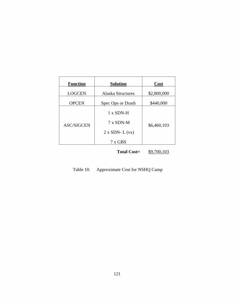
121
Function Solution Cost
LOGCEN Alaska Structures $2,800,000
OPCEN Spec Ops or Drash $440,000
ASC/SIGCEN
1 x SDN-H
$6,460,103 7 x SDN-M
2 x SDN- L (vx)
7 x GBS
Total Cost= $9,700,103
Table 10. Approximate Cost for NSHQ Camp

122
THIS PAGE INTENTIONALLY LEFT BLANK

123
LIST OF REFERENCES
Bobcat. (2011). Bobcat. Retrieved October 25, 2011, from Bobcat: http://www.bobcat.com/loaders/models/track/t770
Brinton, T. (2011, March 18). Pentagon seeing sharp increases for commercial satcom. Retrieved from http://www.spacenews.com/military/20110318-pentagon-price-increases-satcom.html
DigitalGlobe. (2005, May 22). QuickBird imagery products FAQ. Retrieved from http://www.satimagingcorp.com/satellite-ensors/quickbird_imagery_products.pdf
DRASH. (2011). DRASH brochure. DRASH "The Warfighter's Choice." Orangeburg, NY: DRASH.
DRASH. (2011). DRASH hygiene system photo gallery. Retrieved October 26, 2011, from DRASH hygiene system photo gallery: http://www.drash.com/Multimedia/PhotoGallery/ProductPhotos.aspx?GalleryID=26
DRASH. (2011). DRASH M series. Retrieved October 23, 2011, from DRASH M series: http://www.drash.com/userfiles/File/catalog/DRASH-M_Series.pdf
DRASH. (2011). DRASH mobile hygiene system. Retrieved October 1, 2011, from DRASH mobile hygiene system: http://www.drash.com/Products/Shelters/SpecialtyShelters/MobileHygieneSystem.aspx
DRASH. (2011). DRASH shelters. Retrieved October 23, 2011, from drash shelters M series: http://www.drash.com/Products/Shelters/MSeries.aspx
DRASH. (2011, January 10). DRASH systems. Retrieved September 3, 2011, from DRASH: http://www.drash.com/AboutUs/technology/Shelters/DurableDesign.aspx
DRASH. (2011). DRASH XB Shelter System. Retrieved Oct 12, 2011, from DRASH XB Shelter System: http://www.drash.com/Products/Shelters/XBSeries.aspx
Global, H. (2010, September 23). HDT Global fact sheet VDS. Retrieved October 25, 2011, from HDT Global fact sheet VDS: http://www.hdtglobal.com/site_media/uploads/files/HDT_iVDS_Touch_Screen.pdf
Global, H. (2010, September 1). Shade fly. Retrieved Sept 1, 2011, from HDT Global: http://www.hdtglobal.com/products/energy-efficiency/shade-fly/

124
Global, H. (2011). HDT balance of systems. Retrieved October 11, 2011, from HDT balance of systems: http://www.hdtglobal.com/site_media/uploads/files/products/data_sheets/parent/HDT_BOS.pdf
Global, H. (2011). HDT Base-X model 307. Retrieved October 6, 2011, from HDT Global: http://www.hdtglobal.com/products/shelters/base-xreg-shelters/hdt-base-xreg-model-307/
Global, H. (2011). HDT Global. Retrieved OCtober 26, 2011, from HDT Global DCUs: http://www.hdtglobal.com/products/command-control/audio-video-display/digital-control-unit/
Global, H. (2011, January 1). HDT Global air beam shelter system. Retrieved October 10, 2011, from HDT Global air beam shelter system: http://www.hdtglobal.com/products/shelters/airbeamreg-shelters/hdt-airbeam-model-2021/
Global, H. (2011). HDT Global Base-X. Retrieved October 25, 2011, from HDT Global Base- x 307: http://www.hdtglobal.com/site_media/uploads/files/products/data_sheets/parent/HDT_307shelter_e-mail.pdf
Global, H. (2011). HDT Global command and control. Retrieved October 26, 2011, from HDT Global command and control audio visual display: http://www.hdtglobal.com/products/command-control/audio-video-display/
Global, H. (2011). HDT shade fly. Retrieved October 11, 2011, from HDT shade fly: http://www.hdtglobal.com/site_media/uploads/files/products/data_sheets/type/HDT_Shade_Fly.pdf
JP 2-0, Joint Intelligence (2007) from http://www.dtic.mil/doctrine/new_pubs/jp2_0.pdf
Kyle, J. H. (1990). The guts to try. New York: Orion Books.
LaFountaine, E. (2000) Joint Forces Staff Colleg Pub 1. The joint staff officer’s guide 2000. Washington, DC: U.S. Government Printing Office.
McGinnins, M. (2004). Operation Stavanger: Standing up a deployable joint headquarters for the NATO response force. New York: United States Military Academy West Point.
NATO. (2006). Riga NATO Summit 2006, Retrieved from http://www.rigasummit.lv/en/Schisser, S. (2001). Future joint force headquarters. Alexandria, VA: Institute for Defense Analyses.

125
North Atlantic Treaty Organization (NATO). (2010a). 3rd draft MC 0437/2 special operations policy. Shape, Belgium: NATO.
North Atlantic Treaty Organization (NATO). (2010b, February). Final decision on MC 324/2: The NATO military command structure (NCS). Shape, Belgium: North Atlantic Military Committee, International Military Staff.
North Atlantic Treaty Organization (NATO). (2011, January). Draft MC policy for allied forces and their use for operations. Shape, Belgium: International Military Staff.
North Atlantic Treaty Organization (NATO) Parliamentary Assembly. (2004). 156 STCMT 03 E—Weapons in space and global security. Retrieved from http://www.nato-pa.int/default.asp?SHORTCUT=367
North Atlantic Military Committee. (2000, February). Military Decision on MC 400/2 – MC Guidance for the Military Implementation of Alliance Strategy. Shape, Belgium: Secretary General NATO.
North Atlantic Treaty Organization (NATO) Special Operations Coordination Centre (NSCC). (2008, December). North Atlantic Treaty Organization special operations forces study. Shape, Belgium: NATO.
North Atlantic Treaty Organization (NATO) Special Operations Headquarters (NSHQ). (2006, September). NATO special operations forces (SOF) transformation initiative (NSTI) advice. Shape, Belgium: North Atlantic Military Committee.
North Atlantic Treaty Organization (NATO) Special Operations Headquarters (NSHQ). (2009a). Framework nation primer. Shape, Belgium: NATO.
North Atlantic Treaty Organization (NATO) Special Operations Headquarters (NSHQ). (2010c). NSHQ. NATO special operations headquarters. Retrieved from www.nshq.nato.int/NSHQ.
North Atlantic Treaty Organization (NATO) Special Operations Headquarters (NSHQ). (2010d, July). NATO strategic intelligence estimate; Final decision on MC 0161/NSIE/10.Shape, Belgium: NATO.
North Atlantic Treaty Organization (NATO) Special Operations Headquarters (NSHQ). (2011). Biennial review. Shape, Belgium: NSHQ
Radvanyi, R. A. (2002). Operation Eagle Claw—Lessons learned (Master’s thesis, USMC Command and Staff College). Retrieved from http://handle.dtic.mil/100.2/ADA402471
Raytheon. (2011). Global Broadcast Service (GBS). Retrieved from http://www.raytheon.com/capabilities/products/gbs/

126
Spec Ops, Inc. (SOI). (2011). Tactical (smart) tables. Retrieved from http://www.specopsinc.com/tactical_tables.html
Spec Ops, I. (2011). Spec Ops Inc. Retrieved October 26, 2011, from Spec Ops Inc video distribution units: http://www.specopsinc.com/video_distribution_unit.html
Spec Ops, I. (2011). Spec Ops INC. Retrieved October 26, 2011, from Spec Ops INC rapid tactical operations: http://www.specopsinc.com/rapid_tactical_operations_center.html
Structures, A. (2011). Alaska Structures ECUs. Retrieved October 2, 2011, from Alaska Structures ECUs: http://www.aks.com/products/military/?id=68
Structures, A. (2011). Alaska Structures readiness shelter systems. Retrieved October 5, 2011, from Alaska Structures readiness shelter systems: http://www.aks.com/products/military/?id=70
Structures, A. (2011). Alaska Structures small shelter system. Retrieved October 10, 2011, from Alaska Structures small shelter system: http://www.aks.com/products/military/?id=62
Structures, A. (2011). Alaska Structures TOC. Retrieved October 26, 2011, from Alaska Structures TOC: http://www.aks.com/products/military/?id=65
Structures, A. (2011, January 1). Alsaka Structures. Retrieved October 5, 2011, from http://www.alaskastructures.com/products/military/?id=74
Structures, A. (n.d.). Enerlayer Alaska Structures. Retrieved September 1, 2011, from Enerlayer Alaska Structures: http://www.alaskastructures.com/assets/AKS_Enerlayer.pdf
Weatherhaven. (2007, 12). Weatherhaven shelters. Retrieved August 16, 2011, from Weatherhaven fabric shelters : http://www.weatherhaven.com/military/products/fabric_shelters.asp
Weatherhaven. (2011). Weatherhaven MECC. Retrieved October 15, 2011, from Weatherhaven MECC: http://www.weatherhaven.com/commercial/gallery/expandable_mecc.asp
Weatherhaven. (2011). Weatherhaven military images. Retrieved October 22, 2011, from Weatherhaven military images: http://www.weatherhaven.com/military/gallery/fabric_series_4.asp
Weatherhaven. (2011). Weatherhaven military products. Retrieved October 24, 2011, from Weatherhaven military products: http://www.weatherhaven.com/military/products/index.asp
127
Weatherhaven. (2011, June). Weatherhaven SHARC fact sheet. Weatherhaven SHARC fact sheet. Weatherhaven.
Weatherhaven. (n.d.). Weatherhaven SHARC brochure. 2011. Vancouver, British Columbia, Canada: Weatherhaven.
Windmill. (2011). Commercial pricing for Windmill’s KA-10C suitcase portable receive suite. Retrieved December 4, 2011 from Windmill International, Inc. http://www.windmill-intl.com/images/pdfs/SPRS%20Commercial_List%20R4.pdf

128
THIS PAGE INTENTIONALLY LEFT BLANK

129
INITIAL DISTRIBUTION LIST
1. Defense Technical Information Center Ft. Belvoir, Virginia
2. Dudley Knox Library Naval Postgraduate School Monterey, California
3. CAPT Barbara Ford Naval Postgraduate School Monterey, California
4. COL Gregory Wilson Naval Postgraduate School Monterey, California
5. Dr. Keenan Yoho
Naval Postgraduate School Monterey, California
6. LTC Steve Basilici NATO Special Operations Headquarters SHAPE, Belgium 7. LTC Mark Phillips NATO Special Operations Headquarters SHAPE, Belgium


