
Network Layer 4-1
Summary TCP Congestion Control
When CongWin is below Threshold sender in slow-start phase window grows exponentially
When CongWin is above Threshold sender is in congestion-avoidance phase window grows linearly
When a triple duplicate ACK occurs Threshold set to CongWin2 and CongWin set to Threshold
When timeout occurs Threshold set to CongWin2 and CongWin is set to 1 MSS
Network Layer 4-2
TCP sender congestion control
State Event TCP Sender Action Commentary
Slow Start (SS)
ACK receipt for previously unacked data
CongWin = CongWin + MSS If (CongWin gt Threshold) set state to ldquoCongestion Avoidancerdquo
Resulting in a doubling of CongWin every RTT
CongestionAvoidance (CA)
ACK receipt for previously unacked data
CongWin = CongWin+MSS (MSSCongWin)
Additive increase resulting in increase of CongWin by 1 MSS every RTT
SS or CA Loss event detected by triple duplicate ACK
Threshold = CongWin2 CongWin = ThresholdSet state to ldquoCongestion Avoidancerdquo
Fast recovery implementing multiplicative decrease CongWin will not drop below 1 MSS
SS or CA Timeout Threshold = CongWin2 CongWin = 1 MSSSet state to ldquoSlow Startrdquo
Enter slow start
SS or CA Duplicate ACK
Increment duplicate ACK count for segment being acked
CongWin and Threshold not changed
Network Layer 4-3
TCP Throughput
Whatrsquos the average throughout of TCP as a function of window size and RTT
Ignore slow start
Let W be the window size when loss occursWhen window is W throughput is WRTTJust after loss window drops to W2 throughput to W2RTT Average throughout 75 WRTT
Network Layer 4-4
TCP Futures
Example 1500 byte segments 100ms RTT want 10 Gbps throughputRequires window size W = 83333 in-flight segmentsThroughput in terms of loss rate
L = 210-10 WowNew versions of TCP for high-speed needed
Network Layer 4-5
Fairness goal if K TCP sessions share same bottleneck link of bandwidth R each should have average rate of RK
TCP connection 1
bottleneckrouter
capacity R
TCP connection 2
TCP Fairness
Network Layer 4-6
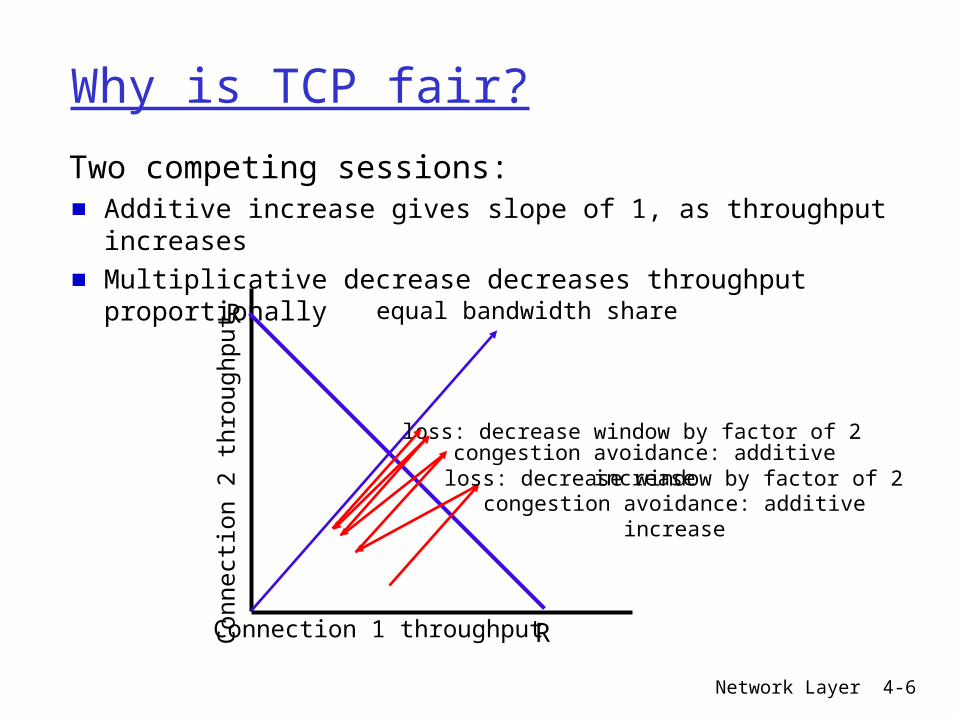
Why is TCP fair
Two competing sessionsAdditive increase gives slope of 1 as throughput increasesMultiplicative decrease decreases throughput proportionally R
R
equal bandwidth share
Connection 1 throughputConnection 2 throughput
congestion avoidance additive increase
loss decrease window by factor of 2congestion avoidance additive
increase
loss decrease window by factor of 2
Network Layer 4-7
Fairness
Fairness and UDPMultimedia apps often do not use TCP
Do not want rate throttled by congestion control
Instead use UDPPump audiovideo at constant rate tolerate packet loss
Research area TCP friendly
Fairness and parallel TCP connectionsNothing prevents app from opening parallel connections between 2 hostsWeb browsers do thisExample link of rate R supporting 9 connections New app asks for 1 TCP
gets rate R10New app asks for 11 TCPs
gets R2
Network Layer 4-8
Chapter 4Network Layer
Computer Networking A Top Down Approach Featuring the Internet 3rd edition Jim Kurose Keith RossAddison-Wesley July 2004
Modified by Jelena Mirkovic
All material copyright 1996-2005JF Kurose and KW Ross All Rights Reserved
Network Layer 4-9
Network layerTransport segment from sending to receiving host Sending side encapsulates segments into datagramsReceiving side delivers segments to transport layerNetwork layer protocols in every host routerRouter examines header fields in all IP datagrams passing through it
networkdata link
physical
networkdata link
physical
networkdata link
physical
networkdata link
physical
networkdata link
physical
networkdata link
physical
networkdata link
physical
networkdata link
physical
application
transport
networkdata link
physical
application
transport
networkdata link
physical
Network Layer 4-10
Key Network-Layer Functionsforwarding move packets from routerrsquos input to appropriate router outputrouting determine route taken by packets from source to dest
Routing algorithms
analogyrouting process of planning trip from source to destforwarding process of getting through single interchange
Network Layer 4-11
1
23
0111
value in arrivingpacketrsquos header
routing algorithm
local forwarding tableheader value output link
0100010101111001
3221
Interplay between routing and forwarding
Network Layer 4-12
Connection setup
3rd important function in some network architectures
ATM frame relay X25
Before datagrams flow two hosts and intervening routers establish virtual connection
Routers get involved
Network and transport layer service
Network between two hostsTransport between two processes
Network Layer 4-13
Network service model
Q What service model for ldquochannelrdquo transporting datagrams from sender to rcvrExample services for individual datagramsGuaranteed deliveryGuaranteed delivery with less than 40 msec delay
Example services for a flow of datagramsIn-order datagram deliveryGuaranteed minimum bandwidth to flowRestrictions on changes in inter-packet spacing
Network Layer 4-14
Network layer service models
NetworkArchitecture
Internet
ATM
ATM
ATM
ATM
ServiceModel
best effort
CBR
VBR
ABR
UBR
Bandwidth
none
constantrateguaranteedrateguaranteed minimumnone
Loss
no
yes
yes
no
no
Order
no
yes
yes
yes
yes
Timing
no
yes
yes
no
no
Congestionfeedback
no (inferredvia loss)nocongestionnocongestionyes
no
Guarantees
Network Layer 4-15
Network layer connection and connection-less service
Datagram network provides network-layer connectionless serviceVC network provides network-layer connection serviceAnalogous to the transport-layer services but
Service host-to-hostHost has no choice network provides one or the otherImplementation in the core
Network Layer 4-16
Virtual circuits
Call setup teardown for each call before data can flowEach packet carries VC identifier (not destination host address)Every router on source-dest path maintains ldquostaterdquo for each passing connectionLink router resources (bandwidth buffers) may be allocated to VC
ldquosource-to-dest path behaves much like telephone circuitrdquo
performance-wisenetwork actions along source-to-dest path
Network Layer 4-17
VC implementation
A VC consists of1 Path from source to destination2 VC numbers one number for each link
along path3 Entries in forwarding tables in
routers along path
Packet belonging to VC carries a VC numberVC number must be changed on each link
New VC number comes from forwarding table
Network Layer 4-18
Forwarding table
12 22 32
1 23
VC number
interfacenumber
Incoming interface Incoming VC Outgoing interface Outgoing VC
1 12 3 222 63 1 18 3 7 2 171 97 3 87hellip hellip hellip hellip
Forwarding table innorthwest router
Routers maintain connection state information
Network Layer 4-19
Virtual circuits signaling protocols
Used to setup maintain teardown VCUsed in ATM frame-relay X25Not used in todayrsquos Internet
application
transportnetwork
data linkphysical
application
transportnetwork
data linkphysical
1 Initiate call 2 incoming call
3 Accept call4 Call connected5 Data flow begins 6 Receive data
Network Layer 4-20
Datagram networksNo call setup at network layerRouters no state about end-to-end connections
No network-level concept of ldquoconnectionrdquo
Packets forwarded using destination host addres
Packets between same source-dest pair may take different paths
application
transportnetwork
data linkphysical
application
transportnetwork
data linkphysical
1 Send data 2 Receive data
Network Layer 4-21
Forwarding table
Destination Address Range Link Interface
11001000 00010111 00010000 00000000 through 0 11001000 00010111 00010111 11111111
11001000 00010111 00011000 00000000 through 1 11001000 00010111 00011000 11111111
11001000 00010111 00011001 00000000 through 2 11001000 00010111 00011111 11111111
otherwise 3
4 billion possible entries
Network Layer 4-22
Longest prefix matching
Prefix Match Link Interface 11001000 00010111 00010 0 11001000 00010111 00011000 1 11001000 00010111 00011 2 otherwise 3
DA 11001000 00010111 00011000 10101010
Examples
DA 11001000 00010111 00010110 10100001 Which interface
Which interface
Network Layer 4-23
Datagram or VC network
InternetData exchange among computers
No strict timing req
ldquosmartrdquo end systems (computers) simple coremany link types
different characteristicsuniform service difficult
ATMEvolved from telephonyHuman conversation
strict timing reliability requirements
ldquodumbrdquo end systems complexity inside network
- Summary TCP Congestion Control
- TCP sender congestion control
- TCP Throughput
- TCP Futures
- TCP Fairness
- Why is TCP fair
- Fairness
- PowerPoint Presentation
- Network layer
- Key Network-Layer Functions
- Slide 11
- Connection setup
- Network service model
- Network layer service models
- Network layer connection and connection-less service
- Virtual circuits
- VC implementation
- Forwarding table
- Virtual circuits signaling protocols
- Datagram networks
- Slide 21
- Longest prefix matching
- Datagram or VC network
-

Network Layer 4-2
TCP sender congestion control
State Event TCP Sender Action Commentary
Slow Start (SS)
ACK receipt for previously unacked data
CongWin = CongWin + MSS If (CongWin gt Threshold) set state to ldquoCongestion Avoidancerdquo
Resulting in a doubling of CongWin every RTT
CongestionAvoidance (CA)
ACK receipt for previously unacked data
CongWin = CongWin+MSS (MSSCongWin)
Additive increase resulting in increase of CongWin by 1 MSS every RTT
SS or CA Loss event detected by triple duplicate ACK
Threshold = CongWin2 CongWin = ThresholdSet state to ldquoCongestion Avoidancerdquo
Fast recovery implementing multiplicative decrease CongWin will not drop below 1 MSS
SS or CA Timeout Threshold = CongWin2 CongWin = 1 MSSSet state to ldquoSlow Startrdquo
Enter slow start
SS or CA Duplicate ACK
Increment duplicate ACK count for segment being acked
CongWin and Threshold not changed
Network Layer 4-3
TCP Throughput
Whatrsquos the average throughout of TCP as a function of window size and RTT
Ignore slow start
Let W be the window size when loss occursWhen window is W throughput is WRTTJust after loss window drops to W2 throughput to W2RTT Average throughout 75 WRTT
Network Layer 4-4
TCP Futures
Example 1500 byte segments 100ms RTT want 10 Gbps throughputRequires window size W = 83333 in-flight segmentsThroughput in terms of loss rate
L = 210-10 WowNew versions of TCP for high-speed needed
Network Layer 4-5
Fairness goal if K TCP sessions share same bottleneck link of bandwidth R each should have average rate of RK
TCP connection 1
bottleneckrouter
capacity R
TCP connection 2
TCP Fairness
Network Layer 4-6
Why is TCP fair
Two competing sessionsAdditive increase gives slope of 1 as throughput increasesMultiplicative decrease decreases throughput proportionally R
R
equal bandwidth share
Connection 1 throughputConnection 2 throughput
congestion avoidance additive increase
loss decrease window by factor of 2congestion avoidance additive
increase
loss decrease window by factor of 2
Network Layer 4-7
Fairness
Fairness and UDPMultimedia apps often do not use TCP
Do not want rate throttled by congestion control
Instead use UDPPump audiovideo at constant rate tolerate packet loss
Research area TCP friendly
Fairness and parallel TCP connectionsNothing prevents app from opening parallel connections between 2 hostsWeb browsers do thisExample link of rate R supporting 9 connections New app asks for 1 TCP
gets rate R10New app asks for 11 TCPs
gets R2
Network Layer 4-8
Chapter 4Network Layer
Computer Networking A Top Down Approach Featuring the Internet 3rd edition Jim Kurose Keith RossAddison-Wesley July 2004
Modified by Jelena Mirkovic
All material copyright 1996-2005JF Kurose and KW Ross All Rights Reserved
Network Layer 4-9
Network layerTransport segment from sending to receiving host Sending side encapsulates segments into datagramsReceiving side delivers segments to transport layerNetwork layer protocols in every host routerRouter examines header fields in all IP datagrams passing through it
networkdata link
physical
networkdata link
physical
networkdata link
physical
networkdata link
physical
networkdata link
physical
networkdata link
physical
networkdata link
physical
networkdata link
physical
application
transport
networkdata link
physical
application
transport
networkdata link
physical
Network Layer 4-10
Key Network-Layer Functionsforwarding move packets from routerrsquos input to appropriate router outputrouting determine route taken by packets from source to dest
Routing algorithms
analogyrouting process of planning trip from source to destforwarding process of getting through single interchange
Network Layer 4-11
1
23
0111
value in arrivingpacketrsquos header
routing algorithm
local forwarding tableheader value output link
0100010101111001
3221
Interplay between routing and forwarding
Network Layer 4-12
Connection setup
3rd important function in some network architectures
ATM frame relay X25
Before datagrams flow two hosts and intervening routers establish virtual connection
Routers get involved
Network and transport layer service
Network between two hostsTransport between two processes
Network Layer 4-13
Network service model
Q What service model for ldquochannelrdquo transporting datagrams from sender to rcvrExample services for individual datagramsGuaranteed deliveryGuaranteed delivery with less than 40 msec delay
Example services for a flow of datagramsIn-order datagram deliveryGuaranteed minimum bandwidth to flowRestrictions on changes in inter-packet spacing
Network Layer 4-14
Network layer service models
NetworkArchitecture
Internet
ATM
ATM
ATM
ATM
ServiceModel
best effort
CBR
VBR
ABR
UBR
Bandwidth
none
constantrateguaranteedrateguaranteed minimumnone
Loss
no
yes
yes
no
no
Order
no
yes
yes
yes
yes
Timing
no
yes
yes
no
no
Congestionfeedback
no (inferredvia loss)nocongestionnocongestionyes
no
Guarantees
Network Layer 4-15
Network layer connection and connection-less service
Datagram network provides network-layer connectionless serviceVC network provides network-layer connection serviceAnalogous to the transport-layer services but
Service host-to-hostHost has no choice network provides one or the otherImplementation in the core
Network Layer 4-16
Virtual circuits
Call setup teardown for each call before data can flowEach packet carries VC identifier (not destination host address)Every router on source-dest path maintains ldquostaterdquo for each passing connectionLink router resources (bandwidth buffers) may be allocated to VC
ldquosource-to-dest path behaves much like telephone circuitrdquo
performance-wisenetwork actions along source-to-dest path
Network Layer 4-17
VC implementation
A VC consists of1 Path from source to destination2 VC numbers one number for each link
along path3 Entries in forwarding tables in
routers along path
Packet belonging to VC carries a VC numberVC number must be changed on each link
New VC number comes from forwarding table
Network Layer 4-18
Forwarding table
12 22 32
1 23
VC number
interfacenumber
Incoming interface Incoming VC Outgoing interface Outgoing VC
1 12 3 222 63 1 18 3 7 2 171 97 3 87hellip hellip hellip hellip
Forwarding table innorthwest router
Routers maintain connection state information
Network Layer 4-19
Virtual circuits signaling protocols
Used to setup maintain teardown VCUsed in ATM frame-relay X25Not used in todayrsquos Internet
application
transportnetwork
data linkphysical
application
transportnetwork
data linkphysical
1 Initiate call 2 incoming call
3 Accept call4 Call connected5 Data flow begins 6 Receive data
Network Layer 4-20
Datagram networksNo call setup at network layerRouters no state about end-to-end connections
No network-level concept of ldquoconnectionrdquo
Packets forwarded using destination host addres
Packets between same source-dest pair may take different paths
application
transportnetwork
data linkphysical
application
transportnetwork
data linkphysical
1 Send data 2 Receive data
Network Layer 4-21
Forwarding table
Destination Address Range Link Interface
11001000 00010111 00010000 00000000 through 0 11001000 00010111 00010111 11111111
11001000 00010111 00011000 00000000 through 1 11001000 00010111 00011000 11111111
11001000 00010111 00011001 00000000 through 2 11001000 00010111 00011111 11111111
otherwise 3
4 billion possible entries
Network Layer 4-22
Longest prefix matching
Prefix Match Link Interface 11001000 00010111 00010 0 11001000 00010111 00011000 1 11001000 00010111 00011 2 otherwise 3
DA 11001000 00010111 00011000 10101010
Examples
DA 11001000 00010111 00010110 10100001 Which interface
Which interface
Network Layer 4-23
Datagram or VC network
InternetData exchange among computers
No strict timing req
ldquosmartrdquo end systems (computers) simple coremany link types
different characteristicsuniform service difficult
ATMEvolved from telephonyHuman conversation
strict timing reliability requirements
ldquodumbrdquo end systems complexity inside network
- Summary TCP Congestion Control
- TCP sender congestion control
- TCP Throughput
- TCP Futures
- TCP Fairness
- Why is TCP fair
- Fairness
- PowerPoint Presentation
- Network layer
- Key Network-Layer Functions
- Slide 11
- Connection setup
- Network service model
- Network layer service models
- Network layer connection and connection-less service
- Virtual circuits
- VC implementation
- Forwarding table
- Virtual circuits signaling protocols
- Datagram networks
- Slide 21
- Longest prefix matching
- Datagram or VC network
-
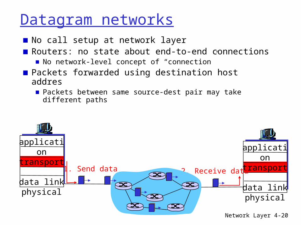
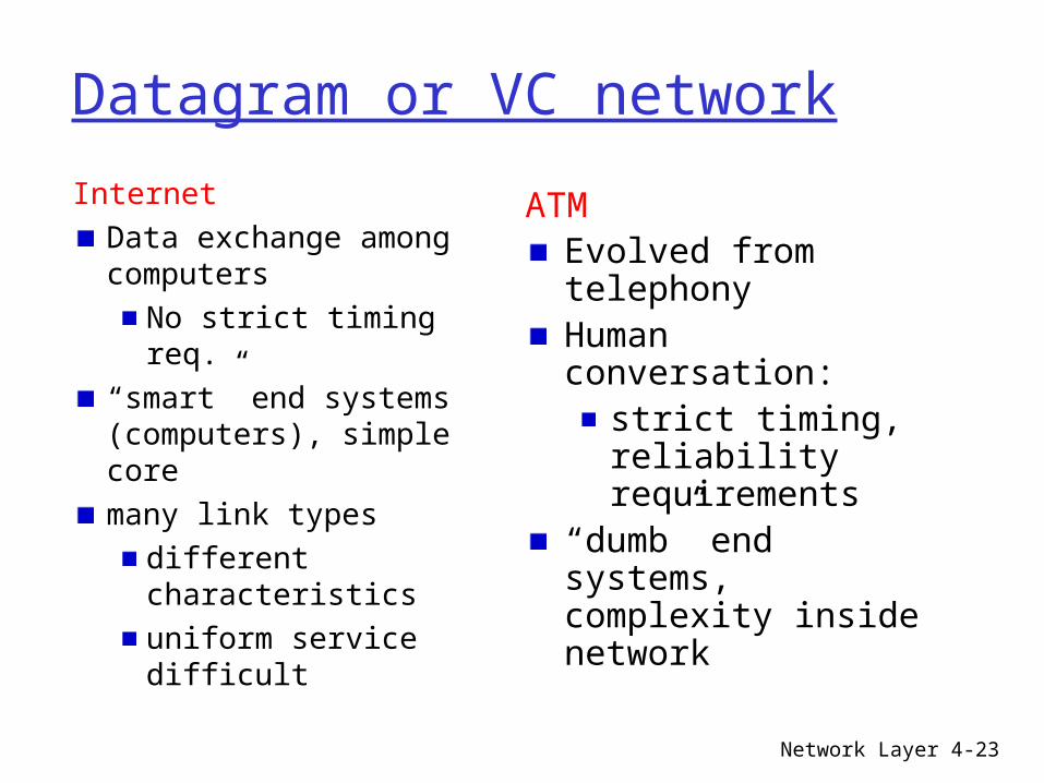


