NEWASH AND TECUMSETH: ANALYSIS OF TWO POST-WAR OF 1812 VESSELS
ON THE GREAT LAKES
A Thesis
by
LEEANNE ELIZABETH GORDON
Submitted to the Office of Graduate Studies of
Texas A&M University
in partial fulfillment of the requirements for the degree of
MASTER OF ARTS
May 2009
Major Subject: Anthropology
NEWASH AND TECUMSETH: ANALYSIS OF TWO POST-WAR OF 1812 VESSELS
ON THE GREAT LAKES
A Thesis
by
LEEANNE ELIZABETH GORDON
Submitted to the Office of Graduate Studies of
Texas A&M University
in partial fulfillment of the requirements for the degree of
MASTER OF ARTS
Approved by:
Chair of Committee, Kevin J. Crisman
Committee Members, Troy O. Bickham
Donny L. Hamilton
Head of Department, Donny L. Hamilton
May 2009
Major Subject: Anthropology
iii
ABSTRACT
Newash and Tecumseth: Analysis of Two Post-War of 1812 Vessels on the Great Lakes.
(May 2009)
LeeAnne Elizabeth Gordon, B.A., Auburn University
Chair of Advisory Committee: Dr. Kevin J. Crisman
In 1953 the tangled, skeletal remains of a ship were pulled from the small harbor of
Penetanguishene, Ontario. Local historians had hoped to raise the hull of a War of 1812
veteran, but the vessel pulled from the depths did not meet the criteria. Identified as
H.M. Schooner Tecumseth, the vessel was built just after the War of 1812 had ended.
Historical research of Tecumseth and her sister ship Newash, which remained in
Penetanguishene harbor, illuminated the ships’ shadowy past. Conceived and built after
the war, the vessels sailed for only two years before being rendered obsolete by the
terms of the Rush-Bagot disarmament agreement. Nevertheless, the two vessels offer a
unique perspective from which to view the post-war period on the Great Lakes.
The schooners’ hulls were interpreted and analyzed using archaeological evidence. A
theoretical rigging reconstruction was created, using contemporary texts and
documentary evidence of the ships themselves. Architectural hull analysis was carried
out to explore the nature of these vessels. From these varied approaches, a conception of
iv
Newash and Tecumseth has emerged, revealing ways in which the hulls were designed to
fulfill their specific duties. The hulls were sharp, yet had capacious cargo areas. The
rigs combined square-rigged and fore-and-aft sails for maximum flexibility. The designs
of the hulls and rigging also reflect predominant attitudes of the period, in which naval
vessels on the lakes gave way to merchant craft.
Taken as a whole, Tecumseth and Newash illustrate how ships, while fluid in the nature
of their work, are also singular entities that truly encapsulate a specific point in time and
place.

v
“If you are flammable and have legs, you are never blocking a fire exit.”
-Mitch Hedberg
vi
ACKNOWLEDGMENTS
The preparation of this thesis could not have been done without the tremendous
assistance of many people who have contributed in various ways. I wish to thank, in no
particular order: Marita and the staff of the Penetanguishene Public Library; Mike
Seraphin and the staff of Discovery Harbour (Havre de la Découverte); Erich Heinold,
Chris Sabick, Eric Emery, Brian Atchison and the other student archaeologists who took
part in the surveys of Tecumseth and Newash in 1997 and 1998; Mr. John R. Stevens;
Captain Walter Rybka, of the U.S. Brig Niagara; Captain Jamie Trost, of the topsail
schooner Pride of Baltimore II; Captain Tiffany Krihwan, of the schooner Denis
Sullivan; the irrepressible and unflappable Ms. Carrie Sowden, to whom I am forever in
debt, financially and otherwise; Mrs. Elizabeth Hutchinson; the thesis committee, Drs.
Kevin J. Crisman, Donny L. Hamilton and Troy O. Bickham; my underrated fellow
students: Heather Brown, Carlos Cabrera, Claire Collins, Ben Ford, Heather Hatch, Brad
Krueger, Ryan Lee, John Littlefield, Bridget McVae, Drew Roberts and Will Moser; my
mom and dad, grandma and grandpa; and of course, the makers of Giant Eagle Bavarian
ham, Lemonheads and, certainly, Dr. Pepper.

vii
TABLE OF CONTENTS
Page
ABSTRACT .............................................................................................................. iii
DEDICATION .......................................................................................................... v
ACKNOWLEDGMENTS......................................................................................... vi
TABLE OF CONTENTS .......................................................................................... vii
LIST OF FIGURES................................................................................................... xi
LIST OF TABLES .................................................................................................... xiv
NOMENCLATURE.................................................................................................. xv
CHAPTER
I INTRODUCTION: THE ROYAL NAVY IN CANADA AND THE
TREATY OF GHENT ......................................................................... 1
II TWO SHARP SCHOONERS .............................................................. 18
III MASTING AND DISMASTING ........................................................ 30
IV LIFE ABOARD THE SCHOONERS .................................................. 42
V THE NEWASH-MINK INCIDENT AND BORDER RELATIONS .... 50
The Case of Lieutenant Alexander Vidal ............................................. 53
Seizure of Julia..................................................................................... 55
Customs House Boats on Lake Champlain .......................................... 56
VI WINTER ON LAKE ERIE .................................................................. 58
Re-Rigging the Ships ........................................................................... 62
Life at Grand River .............................................................................. 64
Crossing the Bar ................................................................................... 65
Later Seasons for the Vessels............................................................... 69

viii
CHAPTER Page
VII CAPTAIN WILLIAM BOURCHIER AND THE DISARMAMENT
OF THE GREAT LAKES.................................................................... 71
The Rush-Bagot Agreement ................................................................. 77
VIII DECAY AT PENETANGUISHENE................................................... 81
IX ARCHAEOLOGICAL AND HISTORICAL RESEARCH................. 87
The 1953 Salvage of Tecumseth........................................................... 88
Early Publications ................................................................................ 91
1970s Examination and Conservation Efforts...................................... 92
1997 – 1998 Archaeology .................................................................... 94
2007 – 2008 Investigations .................................................................. 98
X ARCHAEOLOGICAL EVIDENCE OF THE SCHOONERS’
CONSTRUCTION ............................................................................... 99
Keels and Posts..................................................................................... 100
Deadwood............................................................................................. 108
Frames .................................................................................................. 109
Keelsons, Stemsons and Sternsons....................................................... 111
Mast Steps ............................................................................................ 112
Mast Section......................................................................................... 116
Pump Wells and Limber Holes ............................................................ 117
Clamps, Deck Beams, Waterways and Wales...................................... 118
Chainplates ........................................................................................... 124
Planking the Ships ................................................................................ 126
Newash and Tecumseth and War of 1812-Era Ship Construction ....... 128
XI HULL ANALYSIS .............................................................................. 134
Design Lines......................................................................................... 135
Coefficients and Ratios ........................................................................ 144
Waterplane Area and Immersion.......................................................... 149
Deck-Edge Immersion and Downflooding........................................... 150
Tender and Stiff Vessels ...................................................................... 152
Discussion: Hull Design and Purpose ................................................. 153
Penetanguishene’s Sailing Replica....................................................... 155

ix
CHAPTER Page
XII RECONSTRUCTING THE SCHOONER RIG................................... 158
Main Rigging........................................................................................ 164
Fore Rigging......................................................................................... 166
Bowsprit Rigging ................................................................................. 168
Trestletrees, Crosstrees and Mast Caps ................................................ 170
Topmast Rigging .................................................................................. 170
Topgallant Rigging............................................................................... 173
Jibboom Rigging .................................................................................. 174
Main Yards and Spars .......................................................................... 176
Fore Yards and Spars ........................................................................... 185
Running Rigging .................................................................................. 188
Discussion: Rigging and Manpower ................................................... 193
XIII SAILS AND SAILING ........................................................................ 197
Sail Plan and Area ................................................................................ 200
Mast Placement .................................................................................... 205
XIV RECONSTRUCTION OF THE BRIGANTINE AND
SCHOONER II RIGS........................................................................... 209
The Conversion Factor ......................................................................... 213
Gaff Topsails and Main Topmast Staysails.......................................... 214
XV CONCLUSIONS AND COMMENT ................................................... 216
NOTES……………..................................................................................................... 221
REFERENCES.......................................................................................................... 244
APPENDIX A TREATY OF GHENT.................................................................... 253
APPENDIX B SCHOONER SPARS AND SAILS................................................ 262
APPENDIX C RUSH-BAGOT AGREEMENT ..................................................... 265
APPENDIX D TABLE OF COEFFICIENTS FOR SELECT VESSELS,
1800 - 1832..................................................................................... 268
APPENDIX E “AN ACCOUNT OF RIGGING AND SAILS BELONGING
TO HIS MAJESTY’S SCHOONER NEWASH” ........................... 271

x
Page
APPENDIX F SPAR LENGTH PROPORTIONS FROM HOWARD I.
CHAPELLE’S THE BALTIMORE CLIPPER................................ 276
APPENDIX G E-MAIL COMMUNICATION FROM CAPTAIN WALTER
RYBKA ON THE USE OF HEARTS AND DEADEYES ........... 277
VITA ......................................................................................................................... 279
xi
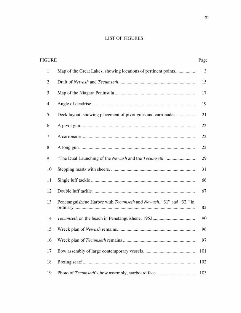
LIST OF FIGURES
FIGURE Page
1 Map of the Great Lakes, showing locations of pertinent points................. 3
2 Draft of Newash and Tecumseth................................................................. 15
3 Map of the Niagara Peninsula .................................................................... 17
4 Angle of deadrise ....................................................................................... 19
5 Deck layout, showing placement of pivot guns and carronades ................ 21
6 A pivot gun................................................................................................. 22
7 A carronade ................................................................................................ 22
8 A long gun .................................................................................................. 22
9 “The Dual Launching of the Newash and the Tecumseth.”........................ 29
10 Stepping masts with sheers. ....................................................................... 31
11 Single luff tackle ........................................................................................ 66
12 Double luff tackle....................................................................................... 67
13 Penetanguishene Harbor with Tecumseth and Newash, “31” and “32,” in
ordinary ...................................................................................................... 82
14 Tecumseth on the beach in Penetanguishene, 1953.................................... 90
15 Wreck plan of Newash remains.................................................................. 96
16 Wreck plan of Tecumseth remains ............................................................. 97
17 Bow assembly of large contemporary vessels............................................ 101
18 Boxing scarf ............................................................................................... 102
19 Photo of Tecumseth’s bow assembly, starboard face. ................................ 103
xii
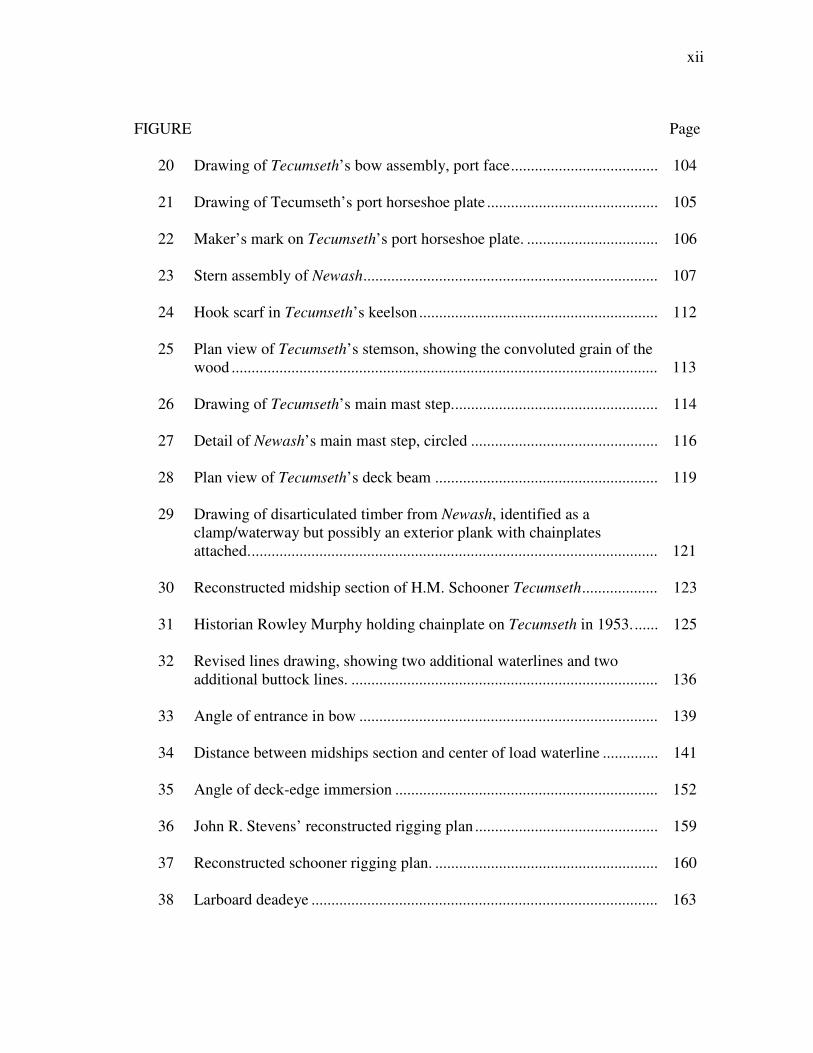
FIGURE Page
20 Drawing of Tecumseth’s bow assembly, port face..................................... 104
21 Drawing of Tecumseth’s port horseshoe plate ........................................... 105
22 Maker’s mark on Tecumseth’s port horseshoe plate. ................................. 106
23 Stern assembly of Newash.......................................................................... 107
24 Hook scarf in Tecumseth’s keelson ............................................................ 112
25 Plan view of Tecumseth’s stemson, showing the convoluted grain of the
wood ........................................................................................................... 113
26 Drawing of Tecumseth’s main mast step.................................................... 114
27 Detail of Newash’s main mast step, circled ............................................... 116
28 Plan view of Tecumseth’s deck beam ........................................................ 119
29 Drawing of disarticulated timber from Newash, identified as a
clamp/waterway but possibly an exterior plank with chainplates
attached....................................................................................................... 121
30 Reconstructed midship section of H.M. Schooner Tecumseth................... 123
31 Historian Rowley Murphy holding chainplate on Tecumseth in 1953....... 125
32 Revised lines drawing, showing two additional waterlines and two
additional buttock lines. ............................................................................. 136
33 Angle of entrance in bow ........................................................................... 139
34 Distance between midships section and center of load waterline .............. 141
35 Angle of deck-edge immersion .................................................................. 152
36 John R. Stevens’ reconstructed rigging plan .............................................. 159
37 Reconstructed schooner rigging plan. ........................................................ 160
38 Larboard deadeye ....................................................................................... 163

xiii
FIGURE Page
39 Rigging heart. ............................................................................................. 163
40 A two-fold purchase. .................................................................................. 165
41 Lanyard and Matthew Walker knots. ......................................................... 167
42 Mast cap. .................................................................................................... 171
43 Swiftering in shrouds ................................................................................. 173
44 Flying jib stay set-up with traveler ring ..................................................... 176
45 Throat and peak halyard assemblies........................................................... 178
46 Boom lift assemblies. ................................................................................. 180
47 Lazy guy assemblies................................................................................... 181
48 Lower yard lift assemblies ......................................................................... 183
49 Sister block................................................................................................. 186
50 Topsail showing cluelines rigged ............................................................... 189
51 Topsail showing cringles............................................................................ 189
52 Bowline assembly ...................................................................................... 191
53 Hypothetical sail plan of original rig.......................................................... 201
54 Center of lateral body. ................................................................................ 204
55 Draft showing predicted fore and main mast placement, in gray............... 206
56 Studdingsails .............................................................................................. 212
xiv
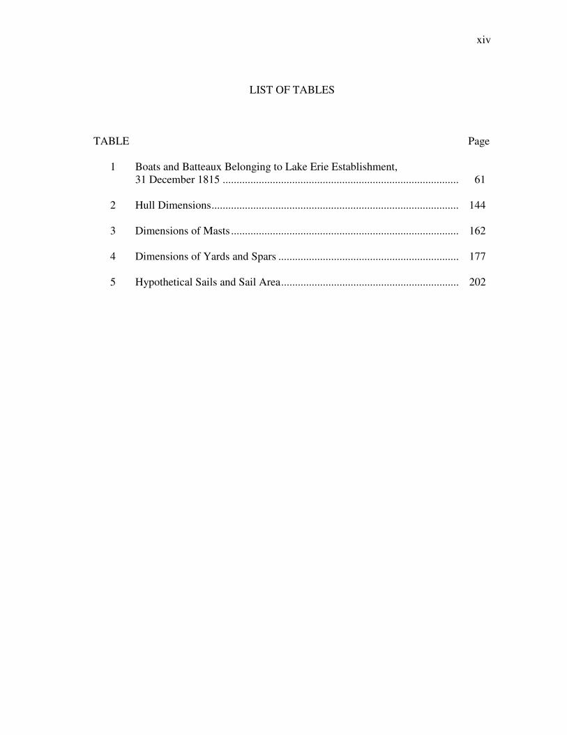
LIST OF TABLES
TABLE Page
1 Boats and Batteaux Belonging to Lake Erie Establishment,
31 December 1815 ..................................................................................... 61
2 Hull Dimensions......................................................................................... 144
3 Dimensions of Masts .................................................................................. 162
4 Dimensions of Yards and Spars ................................................................. 177
5 Hypothetical Sails and Sail Area................................................................ 202

xv
NOMENCLATURE
LAC – Library and Archives of Canada
PRO – Public Record Office
1
___________
This thesis follows the style of International Journal of Naval History.
CHAPTER I
INTRODUCTION: THE ROYAL NAVY IN CANADA AND THE TREATY OF
GHENT
The Treaty of Ghent officially ended the War of 1812 when it was signed on Christmas
Eve 1814. 1
Peace was initially slow to spread, however. When news of the treaty
reached Commodore James Lucas Yeo, senior British officer on the lakes of Canada, he
was little fazed. He did not immediately call for a removal of all troops in Canada, or
for transport ships to convey men back to their homes in Great Britain. Peace between
the United States and Great Britain had been under negotiation in Europe for some time,
and Yeo knew that peace was easier to achieve in a document than on a gundeck. At the
time of the treaty, Yeo was stationed at a location that could not be easily abandoned.
“The situation in 1815 still call[ed] for the maintenance of military and naval measures
designed to prevent an easy conquest of Canada by the United States.”2 The American
desire to conquer Canada had manifested itself during the War of 1812, and led to
several unsuccessful American incursions into territory north of the border. The British,
often with the aid of native tribes, managed to repulse each invasion. Still, the British
were not eager to leave the frontiers, particularly those along the Great Lakes, which
offered a watery passage into Canadian lands, undefended.
2
Commodore Yeo was appointed the commander of His Majesty’s Naval Forces on the
Lakes of Canada in March 1813, just in time to oversee some of the most brutal
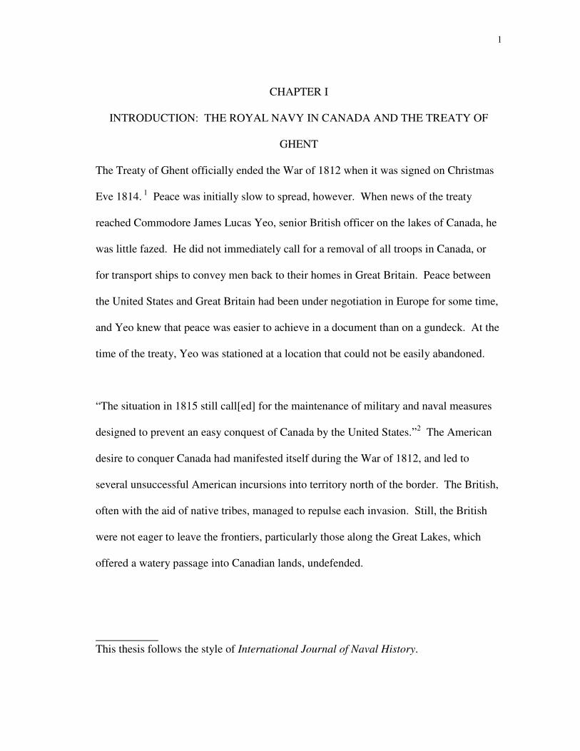
hostilities on the lakes. Yeo was stationed at Kingston, at the northeastern end of Lake
Ontario (fig. 1). Kingston was the key base for the Royal Navy and the headquarters of
its operations in Upper Canada. From Kingston the Royal Navy could keep tabs on
vessels approaching the Saint Lawrence River, as well as traffic on Lake Ontario.
Overland routes linked Kingston to Montreal and Quebec to the east, and fortifications
on the Niagara Escarpment and peninsular Upper Canada to the west. Importantly, the
position at Kingston allowed the British to keep a close eye on Sackets Harbor, the home
of American shipbuilding on Lake Ontario. These bases had been the scene of a
shipbuilding race throughout most of the war, with each side racing to build more and
larger ships than the other in order to achieve ascendancy on the lake.
Yeo was acutely aware of the strategic importance of the lakes of Canada both to the
British and the Americans. On either side of the contested border, the Great Lakes and
the Saint Lawrence River formed a vital highway for communication and commerce. In
war, the water routes had been used to transport troops to distant outposts and keep them
supplied. In peace, the same routes connected loyal settlers on the frontier, providing
needed goods and facilitating trade. Control over, or at least a strong force upon, these
waterways was critical to Great Britain’s continued presence in Upper Canada, and
important to future American expansion as well. In early 1815 Yeo was certain that
naval strength would be maintained by both nations. Prior to receiving word of the

3
Fig
ure
1:
Map
of
the
Gre
at L
akes
, sh
ow
ing
lo
cati
on
s o
f p
erti
nen
t p
oin
ts.
4
treaty, and anticipating future hostilities, he had ordered a number of vessels to be
constructed on Lakes Champlain, Ontario, Erie and Huron, as well as at Montreal on the
Saint Lawrence River. While he awaited further orders from the Navy Board in London
on whether to proceed with these new vessels, Yeo recommended that construction
continue, “to keep pace with the Americans.”3
The end of the war brought a personnel change for the British. Commodore Yeo was
relieved by Commodore Edward William Campbell Rich Owen, while George Prevost,
who had overseen the British Army in Canada during the war, was succeeded by Sir
Gordon Drummond. In spite of the change in commanding officers, the British mission
remained unchanged. Lord Henry Bathurst, Secretary of State for War and the Colonies,
addressed Drummond as he took command of His Majesty’s Forces in Canada. Bathurst
instructed, “[Y]ou will direct Your chief attention to maintaining an ascendancy on the
Lakes.”4 The new vessels ordered by Yeo and overseen by Commodore Owen were
instrumental to this operation.
E.W.C.R. Owen5 was born in 1771, the son of Royal Navy Captain William Owen.
From the time he was just four years old, he was listed in the logbooks of His Majesty’s
vessels. He passed the lieutenant’s exam in 1793 and became a post captain in 1798. A
career naval officer, E.W.C.R. Owen served off the coast of France during the
Napoleonic wars and superintended an attack on Boulogne in 1806. He was awarded the
5
insignia of a Knight Commander of the Bath in 1815. During that same year, he became
senior officer on the lakes of Canada.6
Upon succeeding Yeo, E.W.C.R. Owen set about assessing the state of the navy on the
lakes. Commodore Owen received and analyzed dispatches from the distant bases in
Upper Canada that fell under his jurisdiction. A party under the command of E.W.C.R.
Owen’s brother, Captain William Fitz William Owen, was sent to survey and report on
uncharted portions of the lakes. Accounts from the outposts and the survey party
enabled E.W.C.R. Owen to assemble a collection of observations relative to the natural
resources available in Canada, as well as the requisite forces necessary for their
protection.
British embarrassments on the lakes during the war – specifically the defeats on Lake
Erie and Lake Champlain in 1813 and 1814 – had taken their toll on the Royal Navy,
and it was determined not to repeat such events in any future war. E.W.C.R. Owen
prepared an estimate of the desired naval force on the lakes, which was certainly
influenced by Yeo’s own appraisals. In spite of the Treaty of Ghent, the estimate was
for a “war” complement of men and vessels; the peacetime establishments on the Great
Lakes would ideally be ready for war at any time. The plan called for the construction
of several massive warships, which would be manned by large crews.

6
The proposed war establishment included three 114-gun ships of the line on Lake
Ontario, as well as three 60-gun frigates, two 28-gun corvettes and two 20-gun brigs.
Lake Erie would have been home to a smaller force, consisting of five gunboats
mounting 24-pounder long guns and large carronades, and three 44-gun frigates, to be
built on a plan similar to H.M.S. Princess Charlotte. Another small flotilla was to serve
on the River Thames, a river in peninsular Upper Canada that ran into Lake Saint Clair.
Two more frigates were to be constructed on Lake Huron, as well as four schooner-
rigged transports capable of carrying four guns each, and another smaller transport. The
total number of men stationed on each lake was to be 6230 on Lake Ontario, 1280 on
Lake Erie and 800 on Lake Huron.7
These new vessels were to be outfitted with the latest developments in naval ordnance:
carronades and Congreve guns. Both developments were improvements on the
traditional long gun. The carronade, introduced in the late 18th
century, was a shorter,
thinner-walled weapon capable of hurling heavy shot, but only over short distances.
Some of the carronades planned for the Great Lakes would have been capable of
throwing 68 pounds (30.84 kg) of iron with each blast. The Congreve gun was an
adaptation of the long gun, the result of experimentation by William Congreve.
Congreve hoped to increase effective ranges of guns without reducing the weight of
shot. Initial tests of Congreve’s new design showed that the projectiles had
extraordinarily long ranges but low velocities.8 The vessels of E.W.C.R. Owen’s plan
7
would have carried a combination of carronades, Congreve guns and long guns, making
the British presence on each lake a truly frightening one.
Without an active war, E.W.C.R. Owen’s proposed vessels, establishments and weapons
were outlandish and expensive, and the Royal Navy never achieved such numbers – of
ships, men or armament – on the lakes. Before the end of the War of 1812, however,
some vessels had been ordered and, in a few places, construction had already begun. At
Kingston, the 112-gun H.M.S. St. Lawrence had been launched in September 1814; a 56-
gun ship, H.M.S. Psyche, was launched in December. The keels for two more large
ships had been laid by early 1815. Construction of a frigate for use on Lakes Huron and
Erie was planned at Penetanguishene, on Georgian Bay, and two brigs were underway at
Montreal.9
E.W.C.R. Owen had inherited a precarious perch in Canada. He was to organize and
maintain a peacetime complement of men and ships to be ready for future war at any
moment. He was also tasked with uniting and supplying distant posts without incurring
needless expenses. Logistical problems added to Owen’s difficulties, since the rivers
which connected the lakes to each other and to the sea were filled with rapids or
waterfalls, making navigation impossible in some places.
Owen’s jurisdiction included the Canadian shores of the Saint Lawrence River and
Lakes Champlain, Ontario, Erie, and Huron. Not only was he was responsible for
8
overseeing naval ships on those waterways, but he also had to coordinate with land-
based troops in adjacent regions. The rough terrain of the Canadian interior necessitated
a waterborne transport system for the conveyance of men and supplies. The Royal Navy
was of primary importance in all discussion of Canadian defense. As new military posts
were situated and constructed on the frontier, anchorages and docking facilities were
given consideration. When British troops were removed from Fort Michilimackinac, for
example, the fort was returned to the Americans and a new base was established in
British territory, after the site was approved by a naval official.10
Each of the border waterways shared some portion of its shore with American territory,
and the Treaty of Ghent had promised both nations free navigation of the waters. The
close proximity of a former enemy was an unusual situation for the British Navy. Cut
off as Britain was from the rest of Europe, the Royal Navy was more familiar with
having expanses of open water separating its home ports from potential aggressors. The
size of the Great Lakes, by comparison, gave the British opportunity to keep close watch
on American activities, but also left them exposed to the prying eyes of American spies.
Most of the action on the lakes during the War of 1812 took place only after each of the
navies had exhausted its ability to build and launch more ships than the other. On Lake
Ontario, focal point of the shipwrights’ war, tensions never fully came to a head as each
country waited to engage the other until it was assured of having supreme firepower.
The north-south water highway of Lake Champlain lay mostly within American
territory, but the British could not afford to relinquish control of the entire lake.

9
Maintaining at least one naval base on the water was considered necessary to keep
Americans from encroaching into Canada. The same theory forced the British to retain
outposts on Lake Ontario and the far reaches of Lakes Erie and Huron, despite the
difficulties of transporting stores to support them.
The physical nature of these areas alone presented a logistical nightmare.
Geographically, nearly every body of water was rendered a separate entity by features
that prevented navigation between them. The Saint Lawrence River was effectively two
different rivers during the early 19th century. The Lachine rapids above Montreal
bisected the river and prevented continuous navigation along its length, limiting vessels
on the upper Saint Lawrence River and Lake Ontario to those built there. Lake Ontario
functioned as its own entity, cut off from the upper lakes as well as any outlet to the
Atlantic Ocean. The Niagara River, with its impassable falls, made transportation by
land over the Niagara Escarpment the only option for traveling between Lakes Erie and
Ontario. From Lake Erie, it was possible to reach Lakes Huron and Michigan and ships
could be constructed on either lake for service on all.11
The Great Lakes region was
essentially a series of landlocked waterways.
Construction of canals would eventually link the waters of Upper Canada. A canal
system to bypass the Lachine rapids had been proposed late in the 17th
century, but was
yet to be constructed by 1815. The British Government returned to the idea, and
expanded upon it immediately following the close of the war.12
Geographic difficulties

10
had prevented them from establishing and retaining an upper hand on the disparate
waters of the Great Lakes. Canalization would facilitate the mobility of military and
naval forces in Canada by avoiding geographical limitations. Construction of locks to
bypass the Lachine rapids began in the years after the peace agreement, along with
construction of the Rideau and Welland canals, which linked Ottawa to Lake Ontario
and Lakes Erie and Ontario, respectively.13
At the end of the war, however, canals in Upper Canada were still unknown. A more
immediate solution was to construct more ships. Because ships could not sail into Lake
Ontario from other British outposts, Yeo had ordered two 74-gun ships to be built at
Kingston, for service on Lake Ontario. An establishment was also created on
Penetanguishene Bay, at the southern end of Georgian Bay, upon the recommendation of
Sir Robert Hall, Commissioner of the Kingston dockyard. Hall wrote: “The necessity of
having some naval force on Lake Huron capable of giving protection to the trade of the
Northwest Company and preventing any incursions of the Enemy from Lake Erie
through the River St. Clair has induced me to suggest…a naval establishment in
Penetengushene [sic].”14
The new establishment was located at the southern end of
Georgian Bay, where construction was to begin on several vessels. These vessels could
serve on either Lake Huron or Lake Erie, since a navigable passage existed between
them, via Lake Saint Clair and the Saint Clair and Detroit rivers.
11
Though small, Penetanguishene Bay offered an enviable place for ship construction. A
shore battery easily defended the narrow, steep-sided inlet. The facilities at
Penetanguishene were situated on the eastern side of a spit of land reaching into
Georgian Bay, keeping any new vessels out of sight of casual shipping traffic. In
addition, the surrounding area provided ample timber for shipbuilding and the bay was
deep enough to launch even large vessels. Yeo had ordered two schooners and four
gunboats to be ready by the opening of navigation in 1815.15
In early 1815 British naval
presence on the upper lakes was particularly weak.
The Royal Navy in Upper Canada had been devastated by the Battle of Lake Erie on 10
September 1813. American forces had captured the entire British Lake Erie squadron.
The defeat left the British forces in desperate want of naval ships on the upper lakes.
The British were able to make good some of the losses with the capture of four small
schooners in two separate expeditions in 1814. Lieutenant Miller Worsely, former
commander of H.M. Schooner Nancy, seized the American schooners Scorpion and
Tigress on Lake Huron. Renamed Confiance and Surprize, the schooners were
purchased by the British Army for use by the Royal Navy in carrying supplies. Captain
Alexander Dobbs also captured two American schooners, Ohio and Somers, on Lake
Erie. The two hulls were sunk at the mouth of the Chippewa River to block the entrance
from American traffic. By spring 1815, plans were made to raise the two hulls and
return them to service as transports on Lake Erie.16

12
Transportation of men, supplies and even news, both on and off the lakes was a
tremendous problem. The Battle of New Orleans has always been an ironic postscript to
the War of 1812, fought after the treaty ending the war had been signed, but before news
had spread. New Orleans was not, however, the last place to receive news of peace. The
British commander at Fort Michilimackinac, at the upper end of Lake Huron, received
word of the Treaty of Ghent on 11 May 1815, nearly five months after the treaty had
been signed, and a full two months after a letter containing the news had been
dispatched.17
News was not the only thing that traveled slowly on the lakes, and as the
British were not willing to leave Canada undefended, the Royal Navy was presented
with a new mission, acting as a peacetime shipping organization and border patrol rather
than a navy at war.
The navy took on this new role in peace, but met with the same challenges it had faced
during the war. In 1814 W.H. Robinson, the Commissary General at Montreal, wrote on
the subject:
The difficulties experienced in the transport of Stores and Provisions during the
last Season for the construction, armament, and equipment of His Majesty’s
Ships on Lake Ontario, and for the Supply of the Troops in Upper Canada
imperiously demand that means be promptly devised for a more certain
conveyance of the innumerable Articles necessary for maintaining in that
Province the great, and increasing, Naval and Military Force requisite for its
defence [sic].18

13
This dearth of men and supplies was blamed for the Lake Erie squadron’s failure in
1813; the loss of the fleet only exacerbated these problems.
The problem of transportation of stores was arguably greatest in Upper Canada,
particularly in reaching Fort Michilimackinac; E.W.C.R. Owen determined to build a
small number of transport vessels for service on the upper lakes. Before construction
could begin, however, he was informed that the naval work Yeo had authorized at
Penetanguishene ceased, owing to Drummond’s removal of the military and commissary
departments from Penetanguishene upon receiving news of the Treaty of Ghent. A
desperate need for provisions prevented the shipwrights from continuing any work at the
establishment. The road that was envisioned between Penetanguishene and York was
impassable, preventing any shipment of supplies. The shipwrights therefore headed
back to Kingston to receive instructions on how to proceed.19
Shortly after the shipwrights left Penetanguishene, E.W.C.R. Owen formed a new plan.
Construction on Lake Huron was suspended, and two transport schooners would instead
be constructed on Lake Erie for service on the upper lakes. The lateness of the season
concerned the commodore. In a letter of 6 April 1815, Owen wrote, “I intend no longer
to delay it, and will take immediate measures with the Commissioner for building on
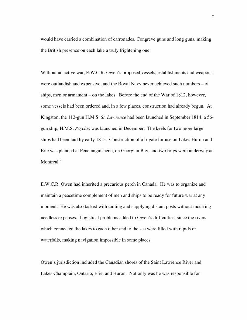
some convenient situation, a couple of sharp vessels.”20
14
A plan for the schooners (fig. 2) was drawn by Robert Moore,21
Assistant Shipwright at
the Kingston yard, and he and a party of shipwrights and artificers – including those who
had recently left Penetanguishene – departed for Lake Erie. The total number of workers
at the Lake Erie shipyard eventually reached 76 shipwrights, 5 blacksmiths, 4 joiners and
12 sawyers.22
With no extant shipyard on the lake, a suitable place had to be located before work could
begin. Sites such as the entrance to the Grand River, which would provide access to
timber growing along the lengthy river’s shores, and Turkey Point, near the Long Point
peninsula, were considered but rejected. Both sites were considered too distant from
established storehouses and too exposed to Lake Erie.
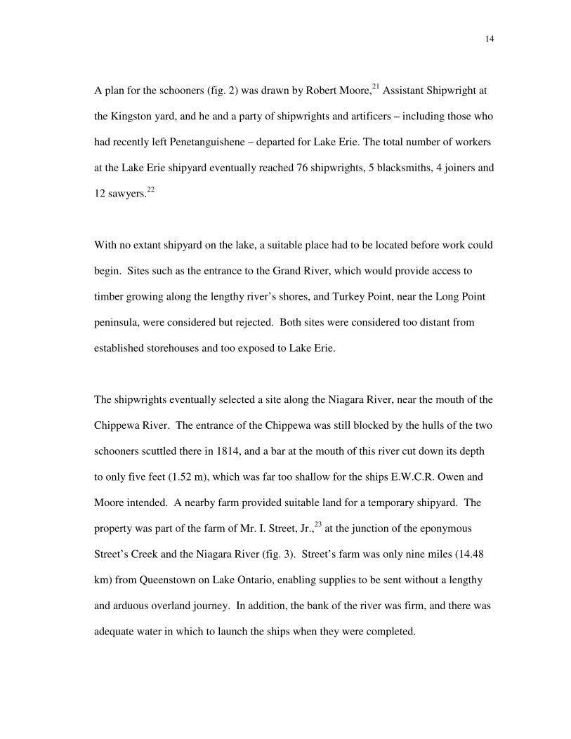
The shipwrights eventually selected a site along the Niagara River, near the mouth of the
Chippewa River. The entrance of the Chippewa was still blocked by the hulls of the two
schooners scuttled there in 1814, and a bar at the mouth of this river cut down its depth
to only five feet (1.52 m), which was far too shallow for the ships E.W.C.R. Owen and
Moore intended. A nearby farm provided suitable land for a temporary shipyard. The
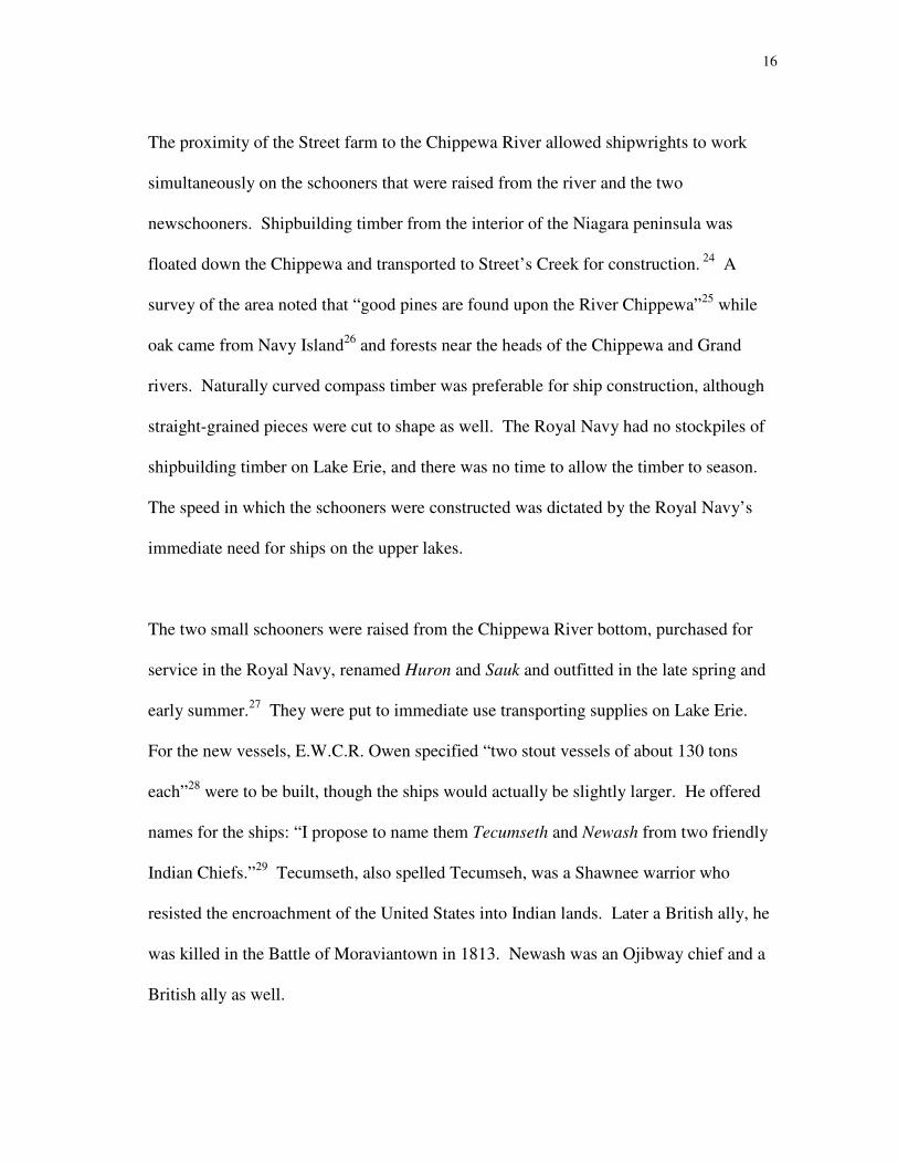
property was part of the farm of Mr. I. Street, Jr.,23
at the junction of the eponymous
Street’s Creek and the Niagara River (fig. 3). Street’s farm was only nine miles (14.48
km) from Queenstown on Lake Ontario, enabling supplies to be sent without a lengthy
and arduous overland journey. In addition, the bank of the river was firm, and there was
adequate water in which to launch the ships when they were completed.
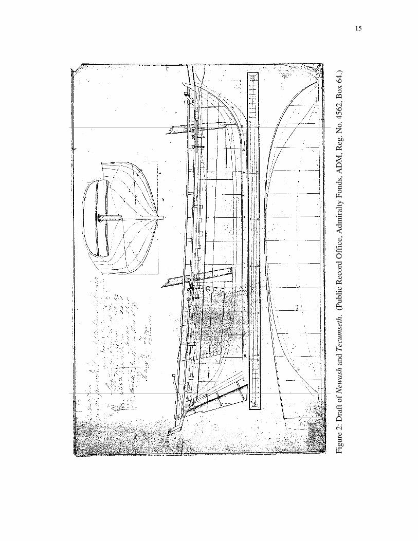
15
Fig
ure
2:
Dra
ft o
f N
ewa
sh a
nd
Tec
um
seth
. (
Pu
bli
c R
eco
rd O
ffic
e, A
dm
iral
ty F
on
ds,
AD
M, R
eg. N
o. 4
56
2, B
ox
64
.)
16
The proximity of the Street farm to the Chippewa River allowed shipwrights to work
simultaneously on the schooners that were raised from the river and the two
newschooners. Shipbuilding timber from the interior of the Niagara peninsula was
floated down the Chippewa and transported to Street’s Creek for construction. 24
A
survey of the area noted that “good pines are found upon the River Chippewa”25
while
oak came from Navy Island26
and forests near the heads of the Chippewa and Grand
rivers. Naturally curved compass timber was preferable for ship construction, although
straight-grained pieces were cut to shape as well. The Royal Navy had no stockpiles of
shipbuilding timber on Lake Erie, and there was no time to allow the timber to season.
The speed in which the schooners were constructed was dictated by the Royal Navy’s
immediate need for ships on the upper lakes.
The two small schooners were raised from the Chippewa River bottom, purchased for
service in the Royal Navy, renamed Huron and Sauk and outfitted in the late spring and
early summer.27
They were put to immediate use transporting supplies on Lake Erie.
For the new vessels, E.W.C.R. Owen specified “two stout vessels of about 130 tons
each”28
were to be built, though the ships would actually be slightly larger. He offered
names for the ships: “I propose to name them Tecumseth and Newash from two friendly
Indian Chiefs.”29
Tecumseth, also spelled Tecumseh, was a Shawnee warrior who
resisted the encroachment of the United States into Indian lands. Later a British ally, he
was killed in the Battle of Moraviantown in 1813. Newash was an Ojibway chief and a
British ally as well.
17
Fig
ure
3:
Map
of
the
Nia
gar
a P
enin
sula
. (
Det
ail
afte
r W
illi
am W
oo
d, S
elect
Bri
tish
Do
cum
ents
of
the
Ca
na
dia
n W
ar
of
18
12
, m
ap #
3.)

18
CHAPTER II
TWO SHARP SCHOONERS
Robert Moore’s draft of the two schooners built at Street’s Farm was made on 23 April
1815, as a plan for the ensuing construction. As drawn, the schooners were of 166 12/94
tons burthen, almost 25 percent larger than Commodore E.W.C.R. Owen’s original
order. The two schooners were envisioned “to be of considerable size and strength.”30
The draft shows they were 70 feet 6 inches (21.49 m) on deck, with an extreme breadth
of 24 feet 5 inches (7.44 m).31
The ships drew 6 feet (1.83 m) of water forward and 9
feet (2.74 m) aft.32
The shallow draft was necessitated by the ships’ employment on the
inland lakes.
Commodore Owen specified that these be “a couple of sharp vessels.”33
Unlike most
cargo ships of this period, which were designed to be capacious with round and full
hulls, sharp vessels were designed to be nimble and sleek. The design of a sharp hull
reduces drag caused by water by trimming the underwater portion. Wherever excess
shape could be cut down, such as the bow, stern and bottom of the ship, the vessel’s
lines were reduced.34
Moore’s draft shows that the vessels were designed to have 12.5° of deadrise at the
midships section, (fig. 4) with raked, or angled, stem and sternpost, and a low profile or
sheer.35
The vessels had the common codfish head/mackerel tail shape, with the widest
points of the hulls forward of the midpoint of their lengths. This shape had been adopted

19
from the natural world, observed in fish with full heads and tapering bodies, which gave
the hull form its name. The maximum breadth of the new schooners was located just 29
feet (8.84 m) aft of the stem, well forward of the midpoint of the overall length. In order
to maintain ample cargo space in the midships hold, the middle of the ship remained full,
while the hull was trimmed in the bow and stern. This reduction in the bow was helpful
when sailing, as there was simply less boat to push through the water. Without the extra
buoyancy provided by a capacious design, however, the bow would have plunged into
oncoming waves as the ship pitched in a headsea, causing spindrift to spray over the
decks.
The crew of the ship lived in the forward and aft ends of the ship. Two transverse
bulkheads are shown in the draft, delineating the crew’s quarters forward and a
Figure 4: Angle of deadrise.

20
wardroom or officers’ quarters aft.36
Traditionally, the bulk of the crew lived in an area
in the bow of the ship once called the forecastle; this was subsequently shortened to
fo’c’s’le.37
Sailors living in the fo’c’s’le slept in canvas hammocks, while the officers
living aft were treated to small bunks. The sole that served as the floor of the aft
quarters was laid parallel to the waterline, while the sole of the fo’c’s’le angled slightly
upward at its forward end. Each of these compartments had 6 feet (1.83 m) of
headroom.38
Between them, the middle of the ship was left open, creating a space
roughly 23 feet by 24 feet (7.01 m by 7.32 m), with a 9-foot (2.74 m) depth of hold.39
In
keeping with the purpose of the ships, the central hold of each was left open and
uncluttered. At the waterline, the ship tapered significantly in the bow and stern,
contributing to her sharpness but amidships, the vessels remained very full to maximize
their capacity for carrying stores.
In addition to transporting stores, it was important that Tecumseth and Newash be
capable of serving as warships in the event of future war with America. The schooners
were designed to carry four guns apiece. The armament was to be two 24-pounder long
guns and two 32-pounder carronades, all carried on the deck. Commissioner Hall
recommended that the guns be placed in such a manner: “two long twenty-four [sic]
pounders abaft the foremast to be used upon the bowers or as broadsides, as occasion
may require, and two carronades abaft the mainmast for the broadsides or quarters.”40
(fig. 5) Two pivot guns (fig. 6) were placed on deck between the masts, and the
carronades abaft the mainmast were placed on carriages. The original orders specified
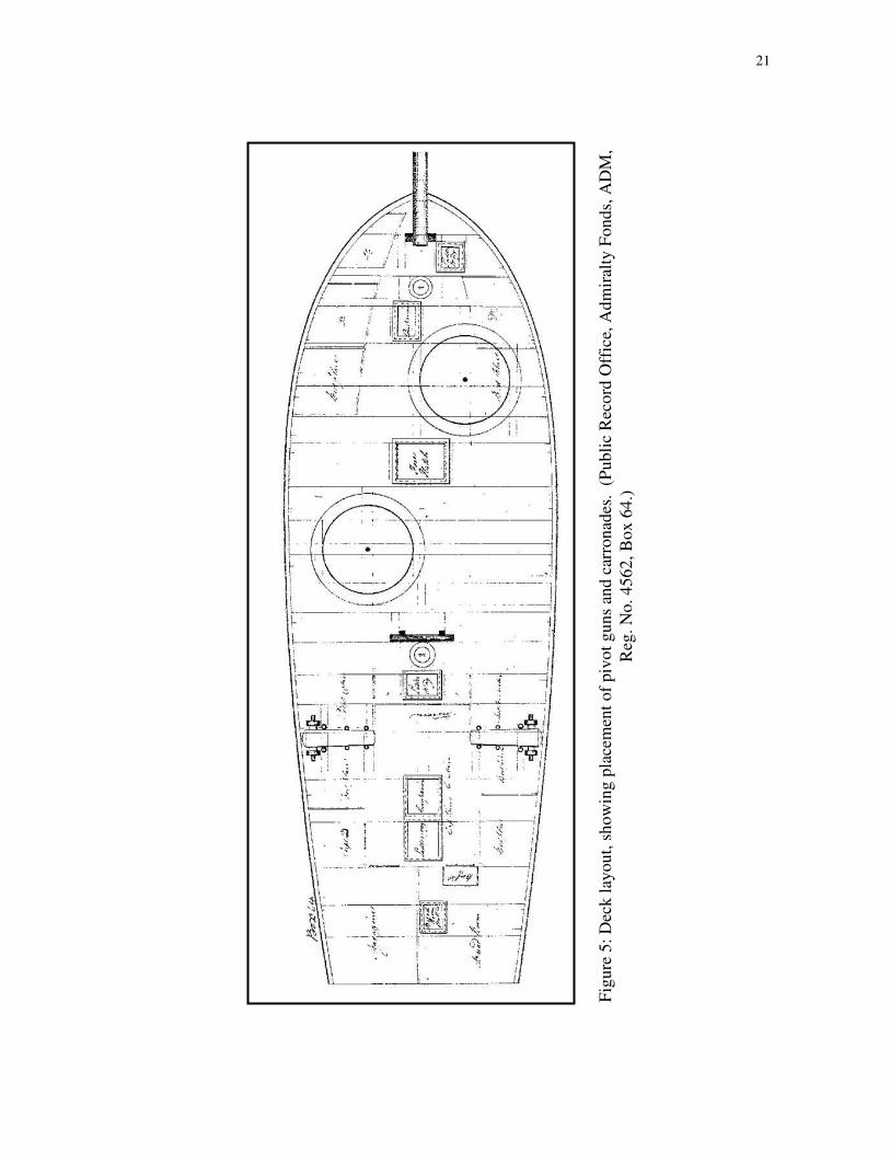
21
Fig
ure
5:
Dec
k l
ayo
ut,
sh
ow
ing
pla
cem
ent
of
piv
ot
gu
ns
and
car
ron
ades
. (
Pu
bli
c R
eco
rd O
ffic
e, A
dm
iral
ty F
on
ds,
AD
M,
Reg
. N
o. 4
56
2, B
ox
64
.)

22
Figure 6: A pivot gun. (Reproduced with permission from
Kevin J. Crisman, The Eagle, 7, fig. 3.)
Figure 7: A carronade. (Reproduced with
permission from Kevin J. Crisman, The
Eagle, 22, fig. 10.)
Figure 8: A long gun. (Reproduced with permission
from Kevin J. Crisman, The Eagle, 22, fig. 11.)
23
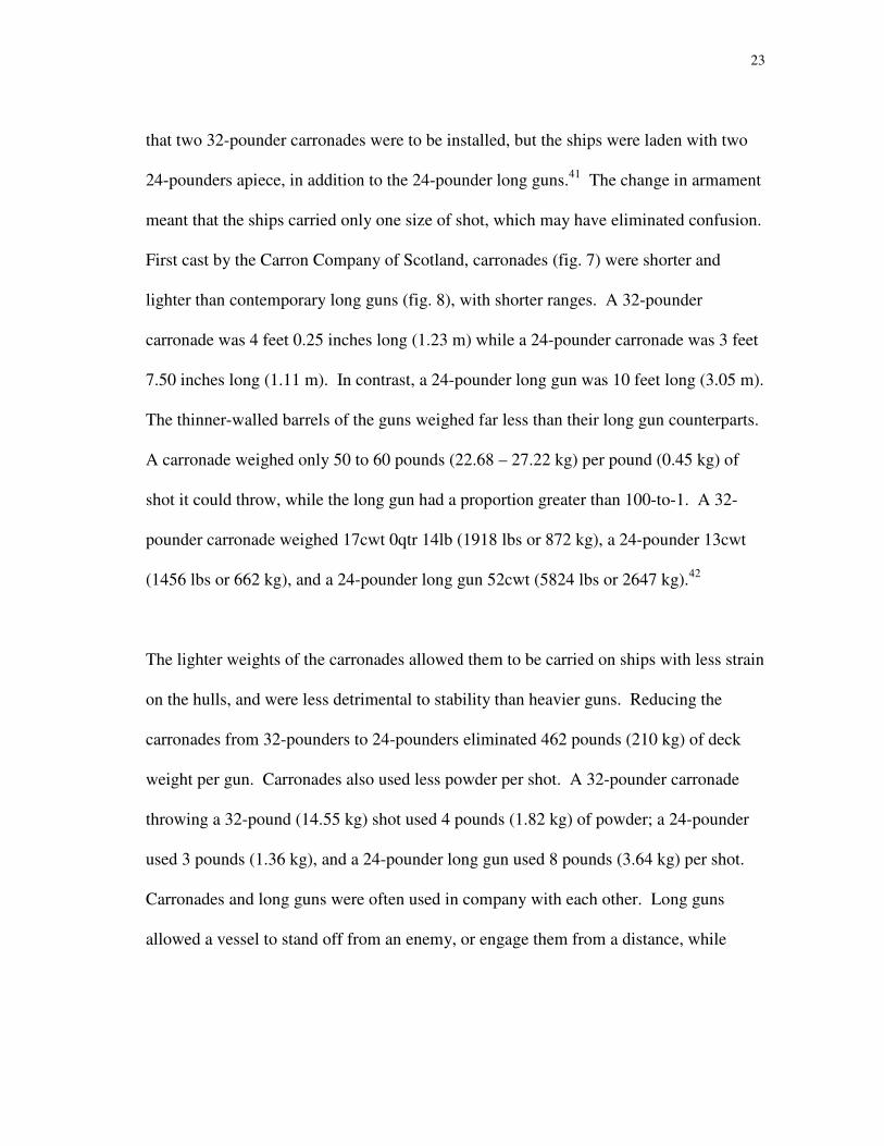
that two 32-pounder carronades were to be installed, but the ships were laden with two
24-pounders apiece, in addition to the 24-pounder long guns.41
The change in armament
meant that the ships carried only one size of shot, which may have eliminated confusion.
First cast by the Carron Company of Scotland, carronades (fig. 7) were shorter and
lighter than contemporary long guns (fig. 8), with shorter ranges. A 32-pounder
carronade was 4 feet 0.25 inches long (1.23 m) while a 24-pounder carronade was 3 feet
7.50 inches long (1.11 m). In contrast, a 24-pounder long gun was 10 feet long (3.05 m).
The thinner-walled barrels of the guns weighed far less than their long gun counterparts.
A carronade weighed only 50 to 60 pounds (22.68 – 27.22 kg) per pound (0.45 kg) of
shot it could throw, while the long gun had a proportion greater than 100-to-1. A 32-
pounder carronade weighed 17cwt 0qtr 14lb (1918 lbs or 872 kg), a 24-pounder 13cwt
(1456 lbs or 662 kg), and a 24-pounder long gun 52cwt (5824 lbs or 2647 kg).42
The lighter weights of the carronades allowed them to be carried on ships with less strain
on the hulls, and were less detrimental to stability than heavier guns. Reducing the
carronades from 32-pounders to 24-pounders eliminated 462 pounds (210 kg) of deck
weight per gun. Carronades also used less powder per shot. A 32-pounder carronade
throwing a 32-pound (14.55 kg) shot used 4 pounds (1.82 kg) of powder; a 24-pounder
used 3 pounds (1.36 kg), and a 24-pounder long gun used 8 pounds (3.64 kg) per shot.
Carronades and long guns were often used in company with each other. Long guns
allowed a vessel to stand off from an enemy, or engage them from a distance, while

24
carronades were employed at close range. At short ranges, the carronade could unleash
a tremendous barrage of iron shot upon an enemy.
Unlike many of the larger ships of the War of 1812 period, the guns on the decks of
Tecumseth and Newash fired over the rail, instead of protruding through gunports cut in
the bulwarks of the ships. The rail remained low and was supported by stanchions. The
decision to keep the rail low and open eliminated the task of assembling bulwarks for the
vessels and reduced excess weight at the topsides of the hull. The stanchions and rail
offered little protection to sailors working on deck, but the armament remained within
sight, a visible reminder of the schooners’ multiple purposes. Though they were
intended as transports, Tecumseth and Newash were also envisioned and built to serve as
warships. In a letter to Drummond, E.W.C.R. Owen stated that the schooners were to be
“adapted to receiving guns and acting as Men of War at any time hereafter if it shall be
necessary.”43
Hall echoed the sentiment, and demonstrated that this purpose was
inherent in the design of the vessels. The schooners were “to be armed as gun vessels on
emergency,”44
but their primary duty was to transport stores. Captain William
Bourchier, who was appointed to superintend the construction of the schooners,45
was
instructed that “such of the Guns as you think proper may be left on shore.”46
Newash and Tecumseth were to carry small arms as well. Owen instructed that “the
Seamen are to be exercised and trained to the use of Small Arms, the same as the
25
Marines; one half of the Seamen of each Are to be armed with Muskets, and the rest
with Cutlass, Pike and Pistol.”47
Captain Bourchier was placed in charge of the Lake Erie establishment, which included
the new schooners as well as Huron and Sauk. Newash and Tecumseth were placed
under the commands of Lieutenants Thomas Bushby and Henry Kent, respectively.
Bushby joined the Royal Navy in May 1811, and passed the lieutenant’s exam on 16
August of that year. When the United States declared war on 18 June 1812, Bushby was
sailing as a lieutenant in H.M.S. Herald, a 20-gun sixth rate. In 1814, he was transferred
to H.M.S. Prince Regent, on Lake Ontario. Over the following year, Lieutenant Bushby
served in His Majesty’s Ships Prince Regent, St. Lawrence, and Montreal on Lake
Ontario before being transferred to Lake Erie.48
Lieutenant Henry Kent, who would take command of H.M. Schooner Tecumseth, had
already had a more colorful career. Kent joined the Royal Navy as a midshipman in
1807. After sailing in several vessels, he obtained the rank of lieutenant in March 1811,
while sailing in H.M.S. La Fantome on the Atlantic.49
In January 1814, 217 crew
members from La Fantome, as well as H.M. Ships Arab, Manly and Thistle left the
Atlantic squadron for Kingston, where the need for men had become dire. Lieutenant
Kent was among those sent to the Great Lakes. After departing their ships in Saint John,
New Brunswick, amidst cheers and celebration, the men were ferried in sleighs 80 miles
26
(128.72 km) to Fredericton. For the rest of the nearly 900-mile (1448.1 km) journey to
Kingston, the men walked with snowshoes and trailed toboggans of provisions. One
hundred ninety-one men arrived on 21 and 22 March 1814, and fourteen stragglers
followed a few days later.50
Upon arrival in Kingston, Kent was appointed first
lieutenant in H.M.S. Princess Charlotte, and commanded her in an attack on the
American fortification at Oswego in May 1814. Lieutenant Kent remained on Lake
Ontario, commanding a flotilla of gunboats,51
until he was transferred to Lake Erie as
construction began on the new schooners.
The keels of Newash and Tecumseth were laid in the middle of May 1815. A forward-
curving stem and aft-raking sternpost were laid at either end of each keel, defining the
vessels’ lengths. Raising frames along the spine of the keel formed the skeletons of the
ships; each frame was comprised of multiple pieces, called floors and futtocks (foot
hooks). Individual planks were laid beside each other and attached to the frames along
the length of the vessel to form the schooners’ skins. Wherever the hulls’ curves became
complex, the planks had to be bent into place. Inside the hull, interior, or ceiling,
planking provided protection for stores and presented a solid surface to stand on. Deck
beams stretched between frames across the width of the ships, and the decks were
planked above the holds.
Two rudders were made, one for each vessel, and hung on the sternposts with pintles and
gudgeons. A tiller controlled each rudder, steering the ship. Tillers were basic steering
27
gear, which were easily constructed at the temporary shipyard, and could be readily
replaced if they became damaged.
The timber for the schooners was supplied from the forests surrounding the Chippewa
and Niagara rivers. The wilderness location of the temporary shipyard meant that some
supplies had to be shipped from other shipyards. In July, Edward Laws, storekeeper at
Kingston, wrote to James Walker, Deputy Storekeeper at Montreal, to request additional
building materials for the new schooners. Montreal was capable of supplying much of
the ironwork needed for the ships’ fittings. Laws’ request included boat nails, door
hinges, metal hinges for the magazine, reaming irons and iron rings. He also mentioned
that “Flat and Round Iron [stock] of each size are much wanted.”52
Much like the ironwork that was shipped to Street’s Creek, sails for the schooners were
also made elsewhere. Some of the larger shipyards in His Majesty’s service employed
sailmakers, riggers, rigging laborers, shipwrights, mastmakers, and top and capstan
makers,53
but the facilities at Street’s Creek were never very elaborate, and did not
include this variety of workers. The shipwrights and crew who arrived at Lake Erie may
have filled multiple roles, and made do with what was available. Despite the distance
from larger, better-equipped shipyards, there is no indication that construction was
delayed for want of any supplies.

28
Before the ships could be launched, ways had to be constructed to allow the hulls to slide
safely into the water. Once these were complete, the empty hulls were ready to leave the
stocks. The interiors of the hulls were whitewashed, and the exteriors were painted black
and yellow above the waterline. Newash and Tecumseth were launched into 12 feet
(3.66 m) of water54
on 13 August 181555
(fig. 9). The schooners were launched without
any armament, and without their sailing rigs. Tecumseth’s lower masts were swayed the
following day, and the bowsprit was in place on 15 August,56
with Newash raising all
three on 15 August as well.57
As the schooners neared completion, Commodore E.W.C.R. Owen visited the shipyard
at Street’s Creek and observed their hulls. Presumably he was satisfied with the vessels
and the skills of their shipwright. In September 1815 the Master Shipwright at Kingston,
Thomas Strickland, was killed in a fall from his horse and Robert Moore was appointed
to succeed him.58

29
Fig
ure
9:
“Th
e D
ual
Lau
nch
ing
of
the
New
ash
an
d t
he
Tec
um
seth
.”
(Rep
rod
uce
d w
ith
per
mis
sio
n o
f th
e
Ro
yal
On
tari
o M
use
um
. ©
RO
M.)
30
CHAPTER III
MASTING AND DISMASTING
Tecumseth and Newash were rigged as schooners, a popular rig on the Great Lakes at the
time. Schooners59
are two-masted vessels with fore-and-aft sails on both masts,
although square sails can also be carried. The combination of fore-and-aft and square
sails provided a measure of flexibility in the schooners’ sail plans. The versatility of the
rig made it appropriate for a variety of wind conditions, which was essential when
sailing on the Great Lakes. As launched, Newash and Tecumseth had identical rigs, with
fore-and-aft fore and main sails, and square topsails and topgallants above on each mast.
The masts were each a two-part assembly, with a lower mast and a topmast, which
included a topgallant pole. A bowsprit and jibboom projected from the front of the each
schooner.
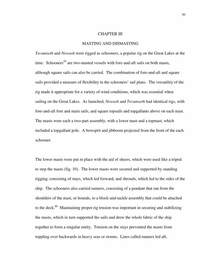
The lower masts were put in place with the aid of sheers, which were used like a tripod
to step the masts (fig. 10). The lower masts were secured and supported by standing
rigging, consisting of stays, which led forward, and shrouds, which led to the sides of the
ship. The schooners also carried runners, consisting of a pendant that ran from the
shoulders of the mast, or hounds, to a block-and-tackle assembly that could be attached
to the deck.60
Maintaining proper rig tension was important in securing and stabilizing
the masts, which in turn supported the sails and drew the whole fabric of the ship
together to form a singular entity. Tension on the stays prevented the masts from
toppling over backwards in heavy seas or storms. Lines called runners led aft,

31
supporting the masts against forward pressure from behind. There were three shrouds on
each side of the lower masts, which acted to restrain the mast from falling to either side.
The tautness of the shrouds transferred the load of the full sails to the hull of the ship.
The deck stiffened the open end of the “U” or “V” shape of the ship’s hull, preventing
the sides of the ship from caving in. Once the top hamper was raised into place, the top
and topgallant masts and jibboom were also secured with standing rigging. Once again
forward-leading stays61
were rigged. Shrouds were set up on either side of the masts,
though for top and topgallant masts the shrouds were fixed to the rigging of the mast
below, rather than running all the way to the sides of the hull. Additional strength was
provided by backstays, which opposed forward-leading stays and did run all the way to
the sides of the ship. In the front of the vessel, the bowsprit and jibboom were secured
Figure 10: Stepping masts with sheers. (Detail
after Darcy Lever, 17, fig. 144.)

32
in a very similar manner as the masts, although on a level closer to horizontal than
vertical.
In addition to securing the masts individually, the standing rigging also acted to unite the
various parts of the rig. The fore lower mast stays led to the bowsprit, and the bowsprit
was connected to the stem with bobstays. The fore topmast stays ran to the bowsprit and
jibboom, and the main topmast stays ran to the fore lower mast. The whole rig was
drawn together with the standing rigging. The actual tensioning of the rig was an art that
allowed all the individual pieces to function as one unit, without any piece bearing too
much of the load. Too much strain on the shrouds could press the hull against the deck,
squeezing the caulking out from between deck planks. Too little strain on the shrouds
and stays and the masts would move unnecessarily, increasing pressure on the mast
partners or maststeps. A loose rig that suddenly came under strain could shockload the
lines, straining them beyond their breaking strengths and potentially causing damage to
the ship and her crew.
Newash and Tecumseth’s rigging was made of fiber rope. The fore shrouds alone were
made from 1.50-inch (3.81 cm) diameter rope. Higher in the rigging, smaller diameter
cordage was used, since the top and topgallant masts were much smaller in size than the
lower masts and the necessary tension was distributed over a longer run of rope. The
thick ropes formed a supporting network for the masts, but they served another purpose
as well. Whenever any work had to be done aloft, sailors used the stiff spiderweb

33
created by the standing rigging as a series of ladders. Horizontal “rungs” called ratlines
were created by tying lines between the shrouds. By using ratlines and shrouds, a sailor
could climb aloft to furl or unfurl sails. As a ship heeled over in a breeze, the shrouds to
the weather side of the ship, closer to the wind, became slightly tighter than those on the
leeward side – the side further away from the wind. These “weather shrouds” were the
choice of any seaman who had to climb aloft into the rig while the ship was underway.
Not only were the shrouds slightly tighter, but the wind blew the sailors towards the
shrouds, rather than away from them, and as the ship heeled the weather shrouds
provided a more comfortable angle for sailors to climb.
Newash and Tecumseth were each set up with hemp rigging. As the rig was tensioned,
the hemp fibers stretched. If the rig stretched too much, it would need to be tensioned
again. Shortly after Newash was launched, the lower rig was used in an attempt to heave
her down. This was done to remove a cleat, probably used to attach a supporting
structure before the launch, which remained on Newash’s bottom.62
Shipwrights were
concerned that the cleat would hamper the vessel under sail. To heave the schooner
down, purchase blocks were attached at the heads of the fore and main lower masts, and
lines were run through the blocks and secured to an anchoring point, probably on shore.
Hauling on these lines caused the vessel to careen over to one side, exposing her bottom.
The new standing rig had stretched and was slack, however, and the load of the ship fell
upon the masts themselves. The masts began to give way.63
The vessel was quickly
34
righted, the blocks removed from the mastheads, and Newash’s rigging was set up
afresh. The cleat remained on the bottom of the hull.
By 25 August 1815, both schooners had swayed and crossed all the masts, yards, gaffs
and booms and bent their sails on. The sails were attached to yards and gaffs or parts of
the standing rigging. Other hemp lines led down to the deck, which set the sails,
controlled their attitude, or hauled them down. These lines formed the running rigging,
which allowed the sailors to do a majority of the work of sailing from the safety of the
deck. The full complement of sails for each schooner consisted of a flying jib, standing
jib, gaff foresail, square-rigged foresail, fore topsail, fore topgallant sail, boom mainsail,
main topsail and main topgallant sail.64
When they arrived at the temporary shipyard,
Captain Bourchier discovered that the sails provided for Newash and Tecumseth were
disproportionate to the sizes of their masts, so “as to be absolutely useless.” 65
With no
sailmaker on Lake Erie, new sails would have to be made at Montreal and sent west.
Disproportionate sails can be problematic when sailing. A sail that was too large could
not be tensioned by the existing masts and yards. Without proper tension at the head and
edges of a sail, a proper shape cannot be achieved, and the sails will not attain their full
driving force. An undersized sail provided less sail area than the spars permitted, but a
small sail could still be stretched to the proper tension. It is not known whether the
schooners’ sails were too large or too small.
35
Even without proper sails, the vessels prepared to get underway. On their first passage,
Newash and Tecumseth each carried shipwrights and officers, as well as dockyard stores
and provisions. The voyage would take the ships both to Fort Erie, at the junction of the
Niagara River and Lake Erie, and Grand River. The latter was to become the home of
the new naval establishment on the lake. Before departing, the vessels received their
first installment of provisions for shipboard life. Onboard Newash, the crew loaded
3097 pounds (1407.73 kg) of bread, 40 gallons (151.20 l) of rum, 572 pounds (260.00
kg) of beef, 318 pounds (144.55 kg) of pork, 28 pounds (12.73 kg) of raisins, 155
pounds (70.45 kg) of butter, 325 pounds (147.73 kg) of sugar, 313 pounds (145.27 kg) of
cheese, and 37 pounds (16.82 kg) of fresh beef.66
These basic provisions were
occasionally augmented with others, such as chocolate, coffee, tobacco or juice.67
On the morning of 26 August 1815, the two schooners made sail and left the Street’s
Creek yard together. The passage up Niagara River was difficult. The schooners could
only sail against the current when winds were favorable. When the wind shifted they
dropped their anchors and waited for an agreeable breeze. Tecumseth was the first to
anchor off Fort Erie, after running through the rapids at Black Rock on 30 August
1815.68
A logbook kept onboard Tecumseth notes that the current at Black Rock was
running at 7 knots (8.06 mph).69
Newash remained stuck below the rapids a while longer,
running through the next day. At Fort Erie the schooners received more provisions, as
well as iron shot for guns, to carry to Grand River.
36
The vessels stood off and onshore as they made their way from Fort Erie towards Grand
River. In the early morning hours of 2 September, the skies were cloudy with fresh
breezes from the south-southwest, veering to the southwest,70
and the new ships were
still making sea trials. The sails and rigging were new, and the run up the Niagara River
had not given much opportunity for the lieutenants to experiment with different sail
combinations and become familiar with the quirks of their particular schooners. The
vessels stood off into the lake to have more sea room around them. At 6:30 a.m.,
Lieutenant Bushby observed that conditions had become “squally.”71
Captain
Bourchier, sailing in Newash, made this observation: “Tecumseth some distance astern
her rigging being perfectly new had stretched considerably.”72
James Childs, Second
Master73
sailing in Tecumseth, recorded these events:
A.M. Fresh Breezes and Cloudy weather at 1 Double Reefed the Topsail at 730
[a.m.] in stays with fore Sail Brailed up, on Coming head to Wind she Dipped the
Bowsprite [sic] under and carried it away Close to the Gammoning lowered the
Mainsail but before she Could pay off to get her before the wind Both Masts
went by the Board Let go the Best Bower in 9 fathoms [54 feet or 16.46 m] A
heavy swell setting all hands employed Clearing the wreck.74
The physics of the dismasting are evident from Childs’ account. According to the
Beaufort Scale of Wind Force, “Fresh Breezes,” also known as Beaufort Force 5 on a
scale of 1 to 12, can range from 16 to 21 knots (18.41 to 24.17 mph) with a mean wind
speed of 19 knots (21.87 mph). Under these wind conditions, seas are predicted to reach
37
up to 6.6 feet (2.01 m). Even with gusts75
approaching 30 knots (34.52 mph), these were
not particularly hazardous conditions. Childs’ weather observations were made at or
around midnight, however. The wind and seas presumably continued to build
throughout the morning hours, reaching a “heavy swell” after daylight.
With winds blowing from the south-southwest, the schooner could not sail directly into
the wind, but instead had to tack back and forth, alternately standing in towards shore
and off into the lake, to make any headway up the lake. Though the sail configuration at
the time of the dismasting was not recorded, it is evident that the mainsail was set, and
the loose-footed foresail had been brailed up, or taken in, at some point previous. Childs
did not record whether any headsails were carried at the time, but something must have
been set in the forward part of the ship, to balance the mainsail. To sail properly, a
vessel must balance sails along her length. The hull pivots about a balance point, usually
found near the center of the ship. Sails that are set aft of this balance point will cause the
ship to turn into the wind, like a weathervane. Sails forward of this point have the
opposite effect, allowing a vessel’s head to be blown away from the wind. Either of
these motions can be compensated for, to a certain extent, by the angle of the rudder.
The rudder has a limited effect, however, and it is always better to attempt a balanced
sail plan. Any effective sail configuration would balance the sail area by having similar
amounts forward and aft of the balance point.
38
The same principles are used to turn a ship. Manipulation of the center of effort of the
sails can be used to thrust a ship into the eye of the wind. If enough momentum is
carried, the ship can pass through the wind, and end up with the wind on the other side
of the vessel. This is called tacking, and is often employed when a vessel is faced with
an unfavorable breeze. A ship cannot sail directly into the wind, nor can it afford to sit
at anchor until only the favorable breezes come along. When faced with an unfavorable
breeze, a ship can sail as close to the wind, or as high, as possible with the wind on her
port side, then turn and sail as high as possible with the wind on the starboard side. This
is called “beating to weather.” When beating to weather, the ship covers a small amount
of ground in the desired direction, though it sails a long, zigzag path. The turn at the end
of each zigzag is made by either tacking or wearing. Unlike tacking, where the vessel is
pointed into the wind, wearing is accomplished by turning away from the wind. Tacking
is arguably the more difficult maneuver, since it requires precise manipulation of the
sails. Wearing is a more forgiving maneuver, but ground is lost when the vessel turns
away from the wind and crosses her own former path. Tacking may be more efficient,
but it is also a more delicate maneuver, and cannot be performed in all circumstances.
Childs’ described the schooner as being “in stays” at the outset of the events. The
schooner had begun to tack, and she was rounding up into the wind. A ship is
particularly vulnerable as her bow begins to point into the wind. Here, the sails are no
longer filled with wind and acting to drive the ship. The forward momentum of the ship
39
is lost, and she may end up going backwards, a dangerous position for the rudder. The
position of the ship when caught head to wind is called being “in irons” or “in stays.”
Second Master Childs noted that “on Coming head to Wind she Dipped the Bowsprite
[sic].” As the schooner turned into the wind, the swell, which had been building all
morning, overcame the low-lying bowsprit and jibboom. The headrig essentially acted
like the blade of a shovel, thrust under the surface of the water as the ship pitched. As
the ship rose back up, the headrig was weighed down with water. If either of the
headsails were not set at the time, the folds of the canvas might have filled with water,
adding more weight which was harder to shake off. As Captain Bourchier had noted
earlier, the hemp rigging had stretched after its initial tensioning, causing it to lie slack.
Without the standing rigging to support it and transfer the load to the other parts of the
ship, the bowsprit and jibboom carried all the weight of the water itself. Consequently,
the bowsprit broke off close to the stem.
With the mainsail still set and acting like the tail of a weathervane, the vessel remained
caught with her head to the wind. Tecumseth’s crew hurried to get the mainsail down, to
allow the vessel to fall off before the wind, to decrease the pressure of the wind on the
spars and rigging. Childs indicated that the mainsail was lowered, but that the ship did
not pay off quickly enough. With the vessel still pointed directly into the wind, the force
pressed against the masts and yards. The foremast stays had carried away with the
bowsprit, and there was little to prevent the masts from falling backwards. The speed in
40
which everything happened is evident from the scene recorded by Lieutenant Bushby
onboard Newash; he seems to have watched a singular event: “at 7 [a.m.] observed The
Tecumseth’s Masts and Bowsprit go over the side.”76
The schooner had completely dismasted. Remarkably, no one was injured, and the
schooner sat at anchor off Point Abino, recovering what gear could be dragged out of the
water and hauled back onboard. Newash sailed down and anchored near her sister ship
for a time, as the weather continued to deteriorate. “A heavy swell from the SW
[southwest]” caused Newash “to pitch so violently as to render it Impossible to lay at
anchor without Carrying away our Masts.”77
Newash consequently weighed anchor and
made sail, reaching back towards shore. Later that day, Newash’s crew found her fore
lower mast sprung below the mast partners, just under the deck. The mast was woolded,
or splinted, for security and the vessel continued towards Grand River. Tecumseth was a
different story. The crew spent most of the afternoon wrestling sails and spars out of the
water. “At 3 [pm] got all the Wreck in with the running Rigging excepting the Main
Topsail.” Fortunately, she was carrying 36 shipwrights to Grand River, and the crew
and shipwrights formed and rigged jury masts from the wreckage and made their way
back to Street's Creek.
New masts were cut at Black Rock, near the junction of the Niagara River and Lake
Erie, and transported to Street’s Creek. The new main lower mast was stepped on 11
September 1815 and the bowsprit was raised the same day. The fore lower mast,

41
topmasts and jibboom followed, and Tecumseth set sail up the river again on 17
September 1815. A good portion of the salvaged rigging, both standing and running,
must have been reused. Once again, the schooner worked her way out of the Niagara
River, reaching Lake Erie a few days later.
While Tecumseth was being remasted at Street’s Creek, Newash carried on to Grand
River and attended to her own rigging. The fore lower mast was sprung just below the
partners, near deck level. Though the damage had been woolded when it was
discovered, the repair job did not hold. Upon reaching Grand River, the mast was
removed, 6 feet 6 inches (1.98 m) was cut from the bottom,78
and it was stepped again.
Once the mast was repaired, the schooner continued on from Grand River to ferry
provisions between military posts.

42
CHAPTER IV
LIFE ABOARD THE SCHOONERS
The complement of Newash and Tecumseth was 30 men for each schooner. Twenty of
the men were seamen, including the lieutenants and warrant officers. E.W.C.R. Owen’s
instructions allotted the vessels the same number of officers and petty officers as a
schooner of 40 men. There were seven Royal Marines, including a sergeant, and three
ship’s boys on each vessel.79
Some of the men may have originally come from England, like Lieutenants Henry Kemp
and Thomas Bushby. Often, those who had been serving before or during the war were
eager to return to England. With the hope of retaining fresh men and proper morale in
the fleet, Commodore Owen recruited volunteers “from among the Canadian Inhabitants
themselves.”80
The hardships of life on a Royal Navy vessel were magnified on the upper lakes. Even
the peacetime crew of 30 was large for Newash and Tecumseth. Most of the crew were
housed in the fo’c’s’le of the ship. There was little elbowroom in these cramped
confines. The 6 feet (1.83 m) of headroom was only available when the area was not
crowded with sleeping men in slung hammocks.81
Hammocks were provided by the
Royal Navy, as was some clothing. Men took advantage of fresh water in the lakes to
wash clothing and hammocks when necessary.82
Rainwater was also used for washing
clothes or bathing.83
43
Even with sporadic cleaning, the vessels and their crews were not always in the most
attractive shape. To save money, the Navy Office ordered that ships were only to be
caulked and painted once annually, unless absolutely necessary.84
There were fewer
requirements on the men’s hygiene, and the fo’c’s’le must have bordered on atrocious at
times.
Only a small amount of light illuminated the below decks area, coming from open
hatches, lanterns and small deck prisms, or “skylights.”85
In addition to being cramped
and dark, the below decks area was often hot. A stove in the galley86
provided hot meals
and smothering conditions. In the cooler parts of the year, this might have been a
welcome addition to the ships’ equipment, but it was stifling in the summer. With at
least part of the area below the waterline of the vessel, there was little ventilation to
offset the heat.
A crewmember might attempt to escape the heat by spending his off hours on the deck
of the ship. Depending on the hour, the decks might be solemn and peaceful or raucous
and rowdy. The duality of life on a ship could be particularly maddening. The watch
that one spent most of their time with could become as close as family, or could swiftly
turn into one’s worst enemy. The slow roll of a ship rocked by seas could be soothing,
but it might also throw a sailor off balance or even over the side. The low rails of
Tecumseth and Newash offered little to keep a man from sliding off the deck. The rig
and sails dictated the schooners’ potential courses and speeds. A squeaking gaff against

44
a mast might be a familiar, even welcome, sound, but it could also keep the crew awake
at night. The view of the horizon from the yardarm could be stunning and spectacular,
but a glance to the decks below might terrify. The very ships themselves may have been
an escape for those who volunteered for various reasons, yet they might have quickly
turned into virtual prisons for those men. Some sailors became career navy men, sailing
all over the world and into old age, like Commodore E.W.C.R. Owen or Captain
Bourchier. Others deserted, absconding with whatever they could and leaving the ships
behind.
As a preventative measure, naval crews were often kept as many as six months in
arrears. Pay for the months up to 30 September 1815 was not received until 23
December 1815.87
Later, in 1816, Second Master Childs recorded that Tecumseth’s crew
was not paid through 31 December 1815 until 13 June 1816. 88
Artificers working in
Upper Canada were paid slightly more because “the duties on the Upper Lakes are
attended with more personal Inconvenience.”89
To limit their exposure to these
difficulties, E.W.C.R. Owen recommended that the men be rotated in September of each
year, only serving on Lakes Erie and Huron for two years.90
The army’s soldiers in
Upper Canada had been offered additional compensation, in the form of land grants.
Shortly after the end of the war of 1812, sailors in the Royal Navy demanded similar
compensation.91
In return for three years of service, Britain offered 100 acres of land in
what would become the province of Ontario.
45
Until they could settle in the country, the navy provided for the men. Provisions were
periodically loaded on the vessels; shipments might contain fresh and salt meats, flour,
rice, raisins, chocolate, butter, cheese and wine.92
Rum was carried on board and
rationed to the men, as well as tobacco, which was passed out to the crew on Sundays.93
Strict accounting and rationing of provisions was necessary. While in charge of the
establishment on Lake Ontario, Captain W.F.W. Owen gave specific orders for the
men’s meals. “[U]nder my orders…serve them a Hot meal every day during the
Winter…on Sundays the usual allowance of Salt Pork with Pease [sic] – And on every
weekday a [sic] Eleven-Twelfths of a pound of Fresh Beef for every Man of which to
make their broth daily.”94
The provisions were not always the best quality. W.F.W. Owen recorded that the casks
of salt meats were often without pickle and short on contents upon arrival in Upper
Canada.95
Fresh fruits and vegetables were often in short supply as well, in spite of the
proximity of land. During the winter of 1815 – 1816, the Lake Huron fleet suffered
from a lack of produce. No vegetables would grow in the sandy soil near the
establishment, and the river water was said to be impregnated with petroleum.96
Winters were particularly hard on the men. With transportation limited both on and
offshore, the lake establishments were seasonally isolated. The men suffered from
sicknesses such as fevers, pneumonic inflammation, ulcers, frost bite, dysentery and
scurvy.97

46
Even though the ships did not sail during the winters, there was still work to be done.
With the holds empty, they could be thoroughly cleaned and whitewashed.98
Repairs
were made to the sails and rigging. During the winter of 1815 – 1816, several of
Newash and Tecumseth’s sails were altered. Wood was cut and stockpiled for later use.
Shipwrights and carpenters repaired and replaced the ships’ equipment. Tecumseth
added a belfry in the spring of 1816, to house a bell for signaling the change of watches
for the crew. 99
Each watch usually worked a four-hour shift that was timed by an hourglass. Newash’s
rigging warrant specified that the vessel carry 15-second, 30-second, and 30-minute
glasses.100
The half-hour glass was used to keep time during watch with the bell struck
each time the glass was turned. At the end of the first half-hour, the bell rang once. At
the end of the second half-hour, it was struck twice, and another stroke was added for
each half-hour throughout the four-hour watch. When eight bells rang, the crew on deck
knew it was time to be relieved, even if they had no means of telling time.
The 15- and 30-second glasses were used to gauge the vessel’s speed. A long log line
was prepared, of small diameter rope. A “chip” was placed at one end of the line, and
the other was wound onto a spool. The chip was a triangular piece of wood, tied to the
log line at two corners. At the third corner, a peg, which was also attached to the log
line, could be inserted or removed. When the peg was inserted and the chip dropped into
the water, it fell vertically and gave some resistance to the water. If the log line was
47
allowed to pay out, the chip remained relatively still in the water as the ship sailed away
from it. The log line had knots tied every 25 feet (7.62 m) along its length.101
As the
schooner sailed away from the chip, the log line paid out through a sailor’s hand. By
counting the knots for 15 or 30 seconds,102
he could determine the speed of the vessel
through the water. After the sand in the glass had run out, a swift tug on the log line
dislodged the peg in the chip, and it could be hauled back on board.
Like many things used on board a ship, particularly those used over the side, log lines
had a tendency to disappear. Lieutenant Bushby’s account of a six-month supply of
stores includes one of each size hourglass, but eight log lines.103
Bushby also listed four
hand lead lines, which were used for measuring depths of water up to 20 fathoms (120
feet or 36.59 m), and one deepsea lead line. A lead weight was placed on the end of
each of these lines, and marks were made along the line, corresponding to fathoms. The
weight was tossed over the side and a man read the marks to determine the depth of
water. A hollow at the base of the lead held a small amount of tallow; the stickiness of
the tallow brought up a sample of the bottom. The weight on a deepsea line was heavier,
and the rope much longer, than a hand lead.
Bushby also ordered other supplies that were used around the decks. The needs of the
ships left little, if any, free time for the crew. Sails, for example, were regularly set and
struck, and wear and tear took its toll on their fabric after time. The schooners stockpiled
extra canvas for sail repair, as well as twine, needles and tallow. The standing and

48
running rigging, too, needed constant attention and maintenance. Extra tallow, oil,
varnish, paint, turpentine, thimbles, tackle hooks and blocks were kept on hand for
replacement of worn or damaged items and in case of emergency. 104
The ships’ work also required the crews to load and unload provisions and cargo. Some
of the unusual cargo required imaginative stowing arrangements. On at least one
occasion, the schooners carried wheelbarrows,105
two 8-inch (20.32 cm) iron mortars106
and a large case containing “rope machinery.”107
In between loads, the holds were swept
and occasionally whitewashed. Keeping the ships properly balanced with the differing
weights of cargo meant shifting stone108
and iron ballast109
in the bilges. The passengers
carried in the schooners were eclectic as well. Shipwrights, soldiers, a bishop,110
and
even several children111
were brought on board for short voyages.
Passages up and down the lakes brought their own workload. Hands were employed
watching for other vessels and steering. Most or all of the crew was needed to hoist sails
and weigh anchor. Tecumseth and Newash each carried a “best bower” and “small
bower” anchor in the bows. The best bower was the heavier of the two, weighing 8 cwt
2 qrs 0 lbs (952 lbs or 432.73 kg); the small bower weighed 7 cwt 0 qrs 0 lbs (784 lbs or
356.36 kg).112
The heavier anchors were secured with hemp cables, slightly less than 2
inches (5.08 cm) in diameter. With nearly thirty men available to haul on the cable, a
majority of the work of weighing anchor could have been done by hand. A handy billy,

49
a tackle providing purchase, or a windlass was employed when necessary, to lighten the
men’s load.
A windlass is often considered a vital part of a vessel’s equipment, but it is
conspicuously absent from Robert Moore’s draft of the hulls. This may have been a
simple omission on Moore’s part, since Second Master Childs’ logbook verifies the
presence of a windlass. 113
The logbook only contains one reference to the windlass,
however, which may indicate that the windlass was only rarely employed. It is possible
that the 30-man crew, large by the vessel’s standards, had enough strength among its
ranks to perform most of the lifting required in regular circumstances,114
and that the
windlass was only used in exceptional situations.

50
CHAPTER V
THE NEWASH-MINK INCIDENT AND BORDER RELATIONS
On 27 September 1815, the two sister schooners were once again in company with each
other, lying at anchor off Fort Erie.115
Newash was loading stores for transport to
Amherstburg, a British post on the eastern shore of the Detroit River (see fig. 1).
Lieutenant George Surratt, commander of H.M. Schooner Sauk, was returning to his
vessel, lying off Amherstburg. Tecumseth was bound for the naval establishment at
Grand River. On 28 September the two schooners set sail up the lake.
Three days later, Newash was sailing amongst the islands at the western end of Lake
Erie. Bushby observed a small schooner, sailing from the direction of the Detroit River.
With Lieutenant Surratt eager for news of his schooner, Bushby attempted to hail the
other vessel and inquire about the Sauk:
On my passage from Fort Erie to Amherstburg, on the first of October last, I met
a Schooner on the N.W. Side of Middle Island at which I fired a musket, she
hoisted American Colours, as she did not shorten sail nor attempt to pass within
hail, I fired another, she then brought to and hoisted her boat out, I then tacked
and hove to close to her and desired her to send her boat on board, and the
Master came on board, after having inquired where she came from, where she
was bound, and whether she had passed any Men of War at Amherstburg I told
the Master he might proceed.116
51
The American schooner was named Mink, and was said to have been in the employ of
the British Commissariat.117
The incident made a distinct impression on at least one
passenger aboard Mink at the time. Shortly after the schooners’ encounter, an editorial
appeared in the Niagara Journal. The editorial was informed by the events witnessed by
the passenger aboard Mink, although it contained a very different description of the
incident than that recorded by Lieutenant Bushby.
British Outrage!
The American Schooner Mink, Captain Hammond, on her Passage from Detroit
to Buffalo, when passing the British Armed Schooner Nawash, [sic] Lieut.
Drury, [sic] on the 1st Instant, near Ballast Island, about two Miles [3.22 km]
from Put-in Bay, was fired upon by the Schooner without being hailed, or
receiving the least other previous intimation.
–The shot passed just over the Bowsprit of the Mink.– Captain Hammond
immediately hoisted American Colors supposing that to be the object of the
British.– Another shot was then fired from the Schooner, which passed through
the foresail of the Mink, not four feet from where the Passengers were standing
on the Deck.–
Captain Hammond then brought his Vessel to, although there was great danger in
doing it, of falling on the Breakers.
–The British Commander ordered him to send his Boat on board the Nawash
[sic]– the Boat was accordingly got out, and Captain Hammond went aboard.–
52
After making a number of trifling inquiries relative to the News at Detroit, and
the Passengers he had aboard, the British Officer ordered him to return to his
Vessel, without assigning any reason for his outrageous Conduct!118
The unnamed editorialist presumed that the Mink had been brought to so that Lieutenant
Bushby could search for and potentially reclaim British deserters. Seen from that light,
the Newash-Mink incident touched on the tender subject of British impressment of
American citizens.
The matter of impressment had been one of the key aggravations that led the American
government to declare war against the British in 1812. Americans perceived the issue as
a threat to their national sovereignty, and the issue was particularly sensitive to the
Americans. Thomas Jefferson, writing just as he received word of the peace, noted, “I
am glad of it, although no provision being made against the impressment of our seamen,
it is in fact but an armistice, to be terminated by the first act of impressment committed
on an American citizen.”119
Some British officers, however, felt it was within their
rights to reclaim deserters from their forces and in the Great Lakes region desertion was
a problem among the British naval and military ranks.
With the refuge of the American border so close, desertion was an easy solution for
disgruntled sailors, and additional temptations of absconding with money or equipment
often enticed men to leave their posts. Lieutenant James Jackson, commanding H.M.

53
Schooner Huron, reported that three men deserted the vessel with one box containing
500 pounds (₤) and upwards of another 100 pounds (₤) as well as one of the ship’s
boats.120
The next year a similar event occurred on the same vessel. In May 1816,
Edmund Burton, Naval Storekeeper, received 2000 pounds (₤) to cover expenses of the
Lake Erie establishment. Burton joined the crew of the schooner Huron, where word
soon spread of the small fortune on the ship. Three men stole the money and quickly
deserted the schooner.121
The Case of Lieutenant Alexander Vidal
When they could be located, deserters might be pursued by crewmembers from their old
ship, even into American lands. On one such occasion, Lieutenant Alexander Vidal was
imprisoned in Michigan after pursuing a group of deserters from H.M. Schooner
Confiance. The deserters had absconded with two of the schooner’s boats and some
clothes from the vessel’s stores while she was near the head of the Saint Clair River, in
September 1815.122
Lieutenant Vidal pursued the deserters on shore and found one of
the men. The man claimed he had not meant to desert the schooner, and did not object
when he was returned to her. Vidal also learned that the pilfered items were in a public
house, and set out to find them. While on his way, Vidal was accosted by a Michigan
militiaman and arrested. The lieutenant was charged with “forcibly seizing and
transporting a person, name unknown,”123
a charge amounting to impressment.

54
The sailor who had been returned to Confiance later denied that he had sought American
protection, and stated that no force had been used to bring him back to the schooner, but
this was little help to Lieutenant Vidal. After his trial was delayed on several occasions,
Vidal was finally in court Detroit in mid-October.124
The verdict was mixed:
[G]uilty of having riotously and routensly [sic] assembled an armed party to seek
Deserters, with having searched the house of one of the Citizens, and with having
disturbed the peace of the Inhabitants but acquitted…of taking the Man forcibly
from the Land.125
Though the impressment charges did not stand, Michigan Governor Lewis Cass made a
strong statement on the issue. Because of American sentiment on the issue, government
representatives from both sides were consulted on the case. E.W.C.R. Owen brought the
matter to the attention of British secretary Anthony Baker,126
and Cass sought advice
from authorities as well. Vidal was imprisoned for over a month before being brought to
trial. He was forced to pay an “enormous sum”127
of money, including court and
attorney fees, but eventually returned to his ship.
Lieutenant Vidal’s case is probably the most noteworthy concerning a particular
individual, for the controversies that erupted between British and American neighbors
usually concerned vessels. In fact, it was far more common that vessels would be
55
detained in an incident, rather than individuals who might have been involved. Two
incidents, one on Lake Ontario and the other on Lake Champlain, reflect this tendency
and suggest that tensions were high all along the border, not only on the western frontier.
Seizure of Julia
On Lake Ontario the British and American shipbuilding centers were in close proximity,
both located at the eastern end of the Lake. In mid-October 1815, the schooner Julia
was sent to the American shore to procure a load of hay that had been purchased for the
dockyard cattle.128
Julia was a merchant vessel, captained by John Robson, but was in
the employment of the Royal Navy dockyard at Kingston. On 15 October 1815, a boat
with eight men from the American post at Sackets Harbor intercepted the schooner.
Julia was taken on orders from the Customs Collector, and detained for “Violating their
Laws in not entering at the Custom House, and for taking away the produce of the
country, without giving any account of it.”129
The Americans struggled to get the schooner underway. Robson had tucked the
schooner into a temporary anchorage, with a shoal nearby. The diligent captain was in a
curious situation, and concerned for the safety of his vessel. “[F]earing loss through
their Ignorance they might run her aground; [Robson] offered to take charge and get her
underweigh [sic].”130
Julia and her crew arrived safely in Sackets Harbor.
The Judge at Sackets Harbor, perhaps realizing the sensitive nature of the circumstances,
determined to write to the American government regarding the schooner. In the
56
meantime, the schooner was detained and the crew returned to Kingston. Captain
Robson was not eager to leave his vessel unattended, regardless of the circumstances.
He remained onboard until ordered to leave on 28 October 1815.131
Customs House Boats on Lake Champlain
The British base on Lake Champlain was actually located ten miles (16.09 km) inside
the Canadian border, on the Richelieu River at Isle Aux Noix. In the fall of 1815, a
United States Customs House boat pursued a vessel into the river. When approached by
Captain William Baumgardt, in charge of the naval establishment at Isle Aux Noix, the
commander of the customs boat claimed the vessel was stolen, then claimed she had
been smuggling. Baumgardt admonished the customs ship’s captain, ordering that the
ship return to her port. He detained the suspect vessel but not her crew, and wrote to
authorities for instructions as to how to proceed.132
Captain W.F.W. Owen, who succeeded his brother, E.W.C.R. Owen, as senior officer on
the Lakes in late 1815, was infuriated by the incursion of the customs boat. He wrote to
Sir Gordon Drummond, then Governor of Upper Canada, to inform him of the
“unnecessarily aggravating and vexatious tenacity” of the American vessel.133
The matter of British and American relations on the Great Lakes weighed heavily on the
minds of both Owen brothers. In late 1815, E.W.C.R. Owen wrote of his concerns
regarding “how much the authority of Government and Justice is weakened by its

57
distance from the seat of the Government, by the irregularity and difficulty of
communication and the want of a Superintending power immediately at hand.”134
He
wanted to strengthen the British presence in Canada, and maintain a military superiority
over the Americans:
To this we may impute in some degree the growth of American feeling and
Connexion [sic] which will require a firm and steady hand to wean them from,
and prove to them (as is the fact) that the Interest of that portion of the United
States which borders on the Lakes is much more in our hands, than that of the
British Colonists can be in theirs.135
W.F.W. Owen was understandably concerned over the state of affairs between the two
countries. He pointed out that “the recent occurrances [sic] on the more distant parts of
the Frontier [have] so much the character of Enmity and so little of a Pacific
disposition.”136
The governments in London and Washington may have been ready for
peace, but in the immediate aftermath of the War of 1812, the atmosphere of amity was
not yet present on the Great Lakes frontier.

58
CHAPTER VI
WINTER ON LAKE ERIE
As the schooners were being built and outfitted at the Chippewa River, work was also
underway at the new naval establishment. The creation of a naval depot on Lake Erie
became necessary, as overland transportation to Lake Huron proved difficult and
unpredictable.137
In early April 1815, E.W.C.R. Owen recommended that an appropriate
area for construction of a Newash/Tecumseth-type schooner be surveyed. John Harris
and John Aldersly were sent to examine several areas along the length of Lake Erie, and
returned a recommendation that the naval establishment be founded on the banks of the
Grand River:
But the most eligible spot that I can find is on the West Bank of the River near
the Mouth of the Grand [where the land] is sufficiently hard to lay ways for
building upon and a sufficient depth of water to launch ships of considerable
burden, capable of being well defended in times of War, when the banks being
high on both sides of the River on the back of which there is almost impassable
Swamps extending up a considerable distance.138
The region also contained gypsum and pigment, and Captain Bourchier learned of “a
considerable vein of lead [which] exists upon a creek which falls into the River.”139
Overland transportation to the establishment at Grand River was far easier than the
routes to Lake Huron, and could be aided by the construction of a canal to Burlington
Bay, on the western shore of Lake Ontario.140
Captain W.F.W. Owen, who had also
surveyed the area, indicated that “The importance of Grand River as a Naval Station
59
must depend very much on its being adopted as a line of communication between the
two lakes.”141
Captain W.F.W. Owen had some concerns over the physical situation at Grand River,
however. The mouth of the river was obstructed by a sand bar, which restricted its
depth. Aldersly described the mouth of the river, the bar, and how the depth was
affected by the weather:142
The mouth of the river is capable of being easily defended, but the bar at the
mouth is so shallow as not to admit vessels of any burthen. The river preserves a
uniform breadth to the mouth, which is narrow, only 132 yards [120.73 m]. I had
an opportunity of seeing the effects of a gale of wind on the bar. The day before
there was 9 feet [2.74 m], the day after only 6 [1.83 m]. The channel over the bar
is very narrow. The river at this period is 4 feet [1.22 m] higher than it has ever
been known. Inside of the mouth here is 30 feet [9.15 m] above this 24 feet [7.32
m] 3 miles [4.83 km] up.143
W.F.W. Owen pointed out that “without measure the bar will only permit vessels which
draw less than 6 feet [1.83 m].” He was of the opinion that “Turkey Point is the best
place for a Naval Force – deep water, good Harbour, room for an arsenal.”
Nevertheless, Grand River was selected for its defensible land and adequate natural
resources, and artificers and stores were sent to create a naval establishment at this
locale. E.W.C.R. Owen wrote, “the first object at the place…will be erecting Barracks
60
and preparing Ground for the future construction or repair of Ships.”144
Aldersly had
noticed an abundance of several types of timber that could be used for ship construction:
Round and upon the banks of the Grand River there is Timber of every
description in abundance applicable to the purposes of Ship Building particularly
oak and Pine. The oak is of the best quality (what we term the Blue
Swampoak)…Pine sufficient for masts of any size…There is also Beech, Ash,
Hickory and Butternut.145
The crews of Tecumseth, Newash, and Huron, which all wintered at Grand River,
plundered the nearby forests of timber for firewood.146
The crews augmented the regular
establishment, which consisted of one quarterman of shipwrights147
, six shipwrights, two
sawyers, two smiths and a horse.148
These men were directed to obey Captain
Bourchier’s orders, but “not to be subjected to naval discipline.”149
The lake
establishment also included four schooners: Newash, Tecumseth, Huron and Sauk. The
two larger schooners each had a crew of 30 men, and the smaller schooners carried 18
apiece.150
Other clerks and artificers, including a sailmaker, a ropemaker and a gunner,
brought the total number of men to 137.151
Getting the larger schooners into the Grand River was a challenge, and a good portion of
the establishment was required to assist when they entered. Captain Bourchier was
certain he could lighten the ships to get them over the bar, but the depth of water was
continually variable. At one point in early fall 1815, E.W.C.R. Owen considered the

61
possibility of constructing a “mole”152
in Mohawk Bay (just off the entrance to Grand
River) to lay the ships up for the winter.153
No mole was constructed, though, and when the schooners arrived in mid-November
1815, they were downrigged and unloaded.154
The unloading of each schooner was
assisted by her own jolly boat, which was hoisted onboard for passages. In addition, the
naval establishment’s ten small vessels (Table 1) were available to give assistance.
Table 1: Boats and Batteaux Belonging to Lake Erie Establishment, 31 December
1815155
Vessel Length Beam Oars How Rowed
Black Gig 25 feet (7.62 m) 4 feet 4 inches (1.32 m) 5 Single-banked
Green Gig 22 feet (7.62 m) 5 feet 0 inches (1.52 m) 5 Single-banked
Yellow Gig 25 feet (7.62 m) 5 feet 5 inches (1.65 m) 6 Single-banked
White
Cutter
25 feet (7.62 m) 7 feet 1 inch (2.16 m) 10 Double-banked
Black
Cutter
25 feet (7.62 m) 6 feet 8 inches (2.03 m) 10 Double-banked
Jolly Boat 16 feet (4.88 m) 6 feet 0 inches (1.83 m) 8 Double-banked
Jolly Boat 16 feet (4.88 m) 6 feet 0 inches (1.83 m) 8 Double-banked
Jolly Boat 15 feet (4.57 m) 5 feet 10 inches (1.78 m) 4 Single-banked
Batteaux 36 feet (10.98 m) 7 feet 8 inches (2.34 m) 10 Double-banked
Batteaux 35 feet (10.67 m) 7 feet 0 inches (2.13 m) 10 Double-banked
*All clinker-built, all steered by rudder except batteaux, which were steered by oar.
The plan to carry the larger schooners over the bar involved deploying an anchor some
distance ahead and hauling the vessels, by hand, to the anchors. Second Master Childs
logged the heaving on 12 November 1815: “[G]ot Purchase on the Cable and heaved
without Difficulty.”156
The next morning, the crew was still at work: “[G]ot all the
62
Marines onboard got a purchase on the Cables all hands heaving…at 2 [pm] hove her off
the Bar and Anchored in the Grand River. [F]ound lying here the Newash.”157
H.M.
Schooner Huron joined the small fleet in the river on 18 November 1815,158
though she
ventured once more into the lake and anchored again in the Grand River on 21
December.159
The schooners lined up on the east bank of the river. The situation of the establishment
had been named Lynnowen,160
perhaps to distinguish it from the rest of the Grand River.
To secure the vessels, they were moored with hawsers led onshore to trees.161
Working
parties from each schooner were sent onshore to assist in gathering firewood and
provisions for the coming winter, as well as to make preparations for the considerable
work which was to take place at Grand River.
E.W.C.R. Owen had directed that Newash and Tecumseth both undergo rigging changes.
He had seen the vessels in person both under construction and later the same month,
after Tecumseth had been remasted.162
Perhaps his recommendations that the rigs be
altered were based on observations made at those times.
Re-Rigging the Ships
It seems evident from Captain Bourchier’s comments and Second Master Childs’
description that Tecumseth’s dismasting in September 1815 was an unfortunate result of
high seas and a loose rig. E.W.C.R. Owen, however, may have suspected a flaw in the

63
sail plan of the schooners. In his instructions for the establishment on Lake Erie, dated
12 October 1815, E.W.C.R. Owen ordered that both schooners’ rigs were to be altered
during the winter of 1815 – 1816.
Newash was to be rigged as a brigantine, with a slightly different sail plan. The
mainmast remained somewhat similar, but the yards that had supported the square sails
were removed. The mainsail was the same, but above it a gaff topsail, a fore-and-aft
sail, was hoisted. The new foremast assembly consisted of a fore lower mast, fore
topmast, and fore topgallantmast;163
each carried a square sail. Between the masts, a
fore-and-aft main topmast staysail was rigged on the main topmast stay. There were two
headsails, called the fore topmast staysail and the jib, and the headrig was supported by
the addition of a sprityard. The sprityard hung horizontally, just below the bowsprit. In
addition to her regular sail plan, Newash could also carry a topmast studdingsail, which
was set outboard of the fore topsail, usually on the weather side. To accommodate this
new rig, the foremast was moved aft, and a new mast step was constructed. John Jewell,
quarterman of shipwrights, recorded “cutting new mast hole” and “shifting three streaks
[strakes] of deck in wake of mast hole” in late December.164
A blacksmith was
employed “making bolts for bolting steps of fore mast and tressle [sic] trees.”165
Tecumseth’s rig was also altered that winter. Like Newash, she was fitted with a gaff
topsail on the mainmast, and a main topmast staysail between the main and fore
masts.166
E.W.C.R. Owen also noted, “To enable the Tecumseth to set her fore topsail
64
lower on the mast by settling the fore yard in bad weather till the topsail yard is close
upon the cap, her schooner foresail is to be fitted with a trysail mast.”167
The trysail
mast was a smaller-diameter mast, stepped on deck immediately abaft the fore lower
mast. The foresail gaff was attached to the trysail mast, while the foreyard, which
stretched the foot of the fore topsail and the head of the square foresail, was attached to
the fore lower mast. This allowed the gaff and yard to be raised and lowered
independently of each other. The two new rigs would remain unchanged until the end of
the vessels’ sailing careers.
Life at Grand River
The shipwrights at Grand River did most of the work to alter the ships’ rigs. That left
the crews to other tasks around the establishment. After the barracks, a blacksmith’s
shop was constructed.168
A working party cut a road from the establishment to Sugar
Loaf, about ten miles (16.09 km) west of Point Abino. On 18 January 1816 the guns
were thoroughly cleaned and a 21-gun salute was fired in honor of His Majesty’s
birthday.169
When a sailmaker onboard Tecumseth added several reef bands to her sails,
the crew made points for the new reefs and also mended the signaling flags.170
The spars
were painted or blacked and the rigging was repaired.171
The schooners were intermittently frozen in the icy river, with snow and rain falling
throughout the winter. Finally, in late March, the ice began to break up around the hulls.
After soundings were taken of the bar at the river’s mouth,172
the vessels began setting
65
up their rigging and bending sails. It would be difficult to transport the large spars of the
rig out to the vessels at anchor, so the rigs were left in place when the ships attempted to
cross the bar. This also allowed the ships to use their sails if necessary. Provisions and
stores were landed onshore by the establishment’s boats to lighten the hulls.
Crossing the Bar
Being the shallowest of the three ships at Grand River, H.M. Schooner Huron was the
first to attempt to cross over the bar, on 18 April 1815.173
A boat’s crew from Tecumseth
was sent to assist in towing her when she struck, to no avail. Eventually, Huron returned
to the river, unable to cross. Tecumseth sent a boat to sound the bar on several
occasions, and a 5- to 5.50-foot (1.52 to 1.68 m) deep channel was found and marked
with buoys. The lightened hull of Tecumseth still drew 7 feet 2 inches (2.18 m) aft and 5
feet (1.52 m) forward. To help raise the schooner higher, casks or puncheons were
lashed under the hull.174
Early on the morning of 22 April 1816 Tecumseth set out, but at 7:45 a.m. struck the
bottom in 6 feet 6 inches (1.98 m) of water. To kedge her off, two anchors were led
ahead of the schooner and for extra purchase in hauling on the cables, a “Luff upon
Luff” purchase was rove. A single luff tackle (fig. 11) provided three times more
hauling power than no tackle at all, and two single luffs together yielded nine times that

66
applied. If double luff tackles (fig. 12) were used, the factor would have been twenty-
five. Childs observed the vessel “Grinding much;”175
with the hull hard aground and
grating across the bar, the crew “Launched the Main Boom and other Spars
overboard.”176
The next morning the operation began anew:
At Daylight a Breeze from the Northward set the [fore] Top Sail Top gallant sail
and Square Sail all hands heaving at Windlass sent powder on shore Galleys and
everything to lighten layed [sic] the…Anchor Out [a]head Sallied the people
from side to side to Clear her Bed Cables Coming in much chafed water Shorting
to five feet four inches [1.63 m] all three Anchors coming home stoppered the
Cables and handed sails.177
Figure 11: Single
luff tackle.
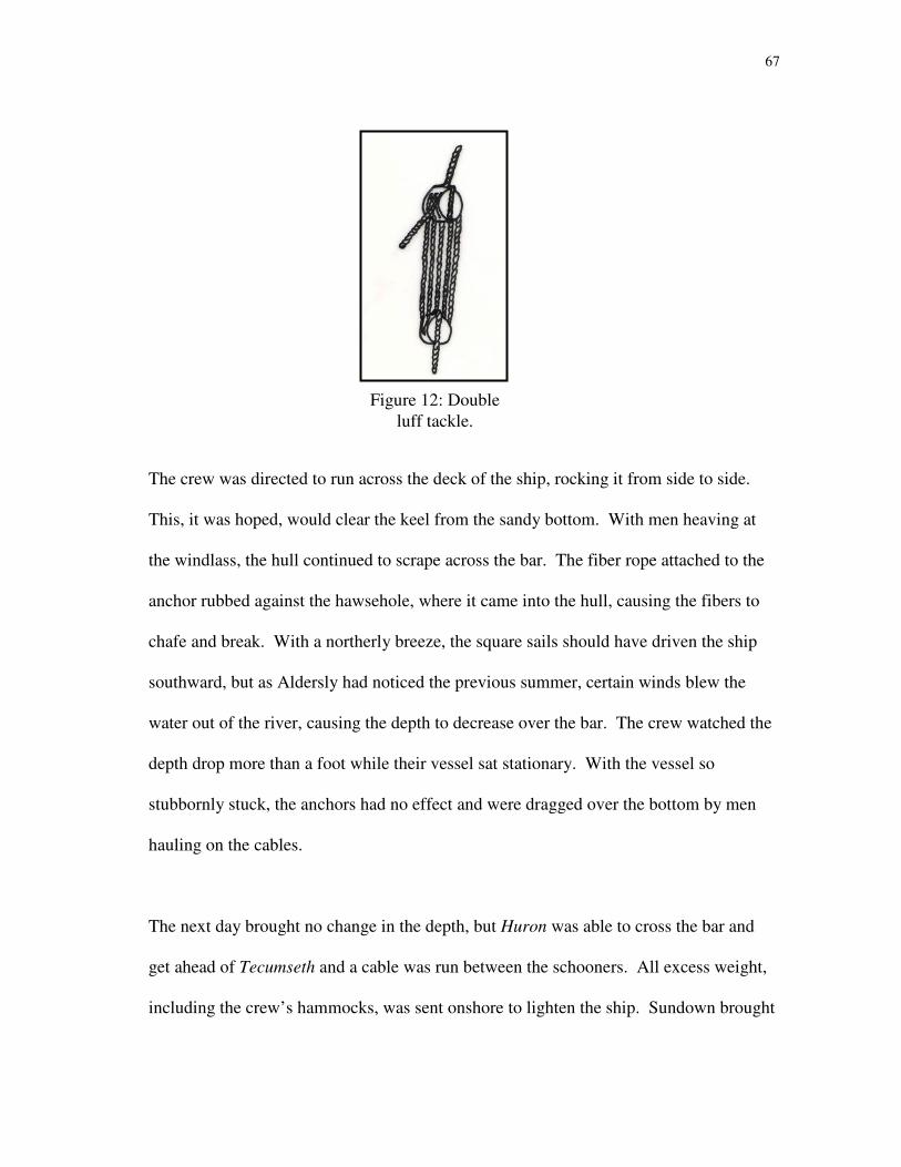
67
The crew was directed to run across the deck of the ship, rocking it from side to side.
This, it was hoped, would clear the keel from the sandy bottom. With men heaving at
the windlass, the hull continued to scrape across the bar. The fiber rope attached to the
anchor rubbed against the hawsehole, where it came into the hull, causing the fibers to
chafe and break. With a northerly breeze, the square sails should have driven the ship
southward, but as Aldersly had noticed the previous summer, certain winds blew the
water out of the river, causing the depth to decrease over the bar. The crew watched the
depth drop more than a foot while their vessel sat stationary. With the vessel so
stubbornly stuck, the anchors had no effect and were dragged over the bottom by men
hauling on the cables.
The next day brought no change in the depth, but Huron was able to cross the bar and
get ahead of Tecumseth and a cable was run between the schooners. All excess weight,
including the crew’s hammocks, was sent onshore to lighten the ship. Sundown brought
Figure 12: Double
luff tackle.
68
no change in Tecumseth’s position, and the hammocks were brought back onboard so the
crew could sleep.178
At daylight on 25 April 1816, the crew was roused and their hammocks again sent
onshore. Later that morning, a breeze filled in from the south and the depth of water
began to increase. Crews from the other ships were brought onboard to haul at the
cables. The efforts of the crews finally paid off on 27 April 1816, six days after the
operation had begun. The depth over the bar had been just over 5 feet (1.52 m), but rose
slowly to “6 and 7 feet [1.83 m and 2.13 m]”179
and the schooner cleared. In spite of all
the efforts to lighten the hull, Childs recorded a draft of 7 feet 7 inches (2.31 m) aft just
after Tecumseth crossed the bar.180
In celebration and acknowledgment of their efforts,
the crew “spliced the Main Brace [were given an extra ration of rum]181
and went to
Dinner,”182
and then set about clearing the decks and preparing to assist Newash over the
bar.
Onboard Newash, the shot and powder were sent onshore, as well as the coppers (used in
the galley for cooking), and fore yard. Casks were bowsed under the hull to raise it.183
With southwesterly breezes on 29 April 1816, Newash hauled off from her anchorage
and stood into the river. She quickly ran aground and sent anchors out to kedge the
vessel off.184
After the amount of time Tecumseth had spent on the bar, a new tactic was
attempted with Newash. The heaving was done from the decks of Huron and
Tecumseth, which were already over the bar. Men from Newash and the naval

69
establishment were sent to the other schooners, to keep Newash’s hull as light as
possible. The empty hull was towed over the bar by the two schooners in the lake.185
Falling water levels plagued Newash as well, and when she finally scraped over the last
of the bar on 1 May, her rudder was unshipped.186
The rudder was re-hung, the rigging
rove, and both ships were ready to sail the lake again in early May.
The whole squadron loaded provisions at Fort Erie and transported them to Nottawasaga
and Drummond Island, on Lake Huron, where British troops had constructed a depot
after leaving their former base at Fort Michilimackinac.187
Perhaps because of the
difficulties and amount of time it took Tecumseth and Newash to cross the Grand River
bar,188
the two vessels were officially transferred to the Lake Huron fleet in 1816, though
they continued operating on both lakes. The depots on Lake Huron – Nottawasaga,
Drummond Island and Penetanguishene – each provided a potentially better situation for
larger vessels. In spite of these better situations, both schooners spent the winter of 1816
– 1817 at Mohawk Bay, just off the mouth of the Grand River.
Later Seasons for the Vessels
Tecumseth and Newash continued to sail the waters of Lakes Erie and Huron, usually in
company with each other. Occasionally, the close proximity of the two ships caused
problems such as two episodes in late 1816 when the ships ran into each other. On 17
November Newash fell onboard Tecumseth and carried away the brigantine’s boat
davit.189
Less than a month later, on 13 December, Newash again fell onboard
70
Tecumseth and carried away her spritsail yard.190
That year, both vessels wintered in
deeper water at Mohawk Bay. The crews kept busy by cutting firewood in nearby
forests, and working on their vessels, and the guns were exercised regularly,191
certainly
a notable event as the noise must have echoed across the icy water.
On 20 April 1817, Newash hoisted the “blue peter,” a signal flag used by an outward-
bound vessel, at the start of what would prove to be her last sailing season. Lieutenant
Henry Kent was in command of Newash, having been transferred the previous fall when
Tecumseth was registered as a Sloop of War and Newash as a Schooner.192
Lieutenant
Thomas Bushby, formerly commanding Newash, was transferred to the schooner Sauk193
and Lieutenant Abraham Whitehead came aboard Tecumseth from Sauk.194
71
CHAPTER VII
CAPTAIN WILLIAM BOURCHIER AND THE DISARMAMENT OF THE
GREAT LAKES
The British officers who commanded squadrons on the lakes of Canada, and some of the
men who worked under them, were used to warfare. These men had come of age
steeped in the Napoleonic wars in Europe, and were offered their own commands during
the War of 1812. Part of the reason for some of their potentially volatile acts on the
frontier may be that they simply did not know how to be officers at peace. W.F.W.
Owen described the task of transporting stores as “a Service so essentially different from
our usual employment.”195
Additionally, the Great Lakes put these officers into a very unique position. The Treaty
of Ghent secured the rights of both nations to navigate the waters of the lakes freely.
While meant as a gesture of reconciliation, this article essentially encouraged smuggling
and asked that whatever authoritarian vessels might observe it to turn a blind eye. On
Lake Erie, Captain Bourchier encountered this situation directly.
Bourchier was a zealous officer who was wary of his assigned post. Lake Erie, like
other frontier posts, was painfully distant from Kingston and familiar British influences.
While at Grand River, Bourchier felt exposed not to Americans but to natives and
Canadian settlers in the region. After the first winter at the establishment, Bourchier
wrote, “If a permanent Establishment is to be formed on the Grand River, I should hope
72
the Government would hold possession of all the Land for Four Miles (6.44 km) up the
River.” He pointed out that “the Timber on the Land would be of use to the Government
and a Mill seat might be found.” It seems that Bourchier did not trust anyone outside of
the Royal Navy. “[T]he less communication with our present neighbours [sic] the better.
Settlers such as we have can be of no use to any Establishment, the Grand River having
been a Rendezvous for Vagabonds.”196
During the winter at Grand River, Bourchier
acted as magistrate both for the men at the naval establishment and settlers on nearby
lands. He felt the duty within his realm, the establishment being so far removed from
any other seat of authority.197
In much the same vein, Bourchier felt obliged to take on the task of enforcing revenue
laws on Lake Erie. At both ends of the lake, American territory was in extremely close
proximity, and the unguarded expanses of Lake Erie allowed plentiful opportunities for
illegal trade and smuggling. Bourchier was certainly aware of the lake’s legacy and
popular sentiments on the late war. Bourchier wrote of his assignment, “I am well aware
we are placed on Lake Erie, on a very ticklish footing.”198
Finding the four vessels – Huron, Newash, Sauk and Tecumseth – under his command
the only royal authority on Lake Erie, Bourchier determined to use them to support the
government of Upper Canada. Bourchier instructed the lieutenants commanding the
vessels to keep a close watch on suspected smugglers. W.F.W. Owen seemed to support
73
Bourchier’s determination, and wrote to Lieutenant Governor Francis Gore in the spring
of 1816 for verification:
[Captain Bourchier] has directed His Majesty’s Naval Officers to aid and support
the Government of this Province in the execution of the Revenue laws, it being
notorious that smuggling is carried on to very great extent on the whole of our
Coast – far as the Thames [River], to the very great detriment of the
Country…The prevention of smuggling would be a direct object of pursuit to
engage the attention of the Naval Service on the Lakes and would operate more
than any other regulation to bring it to perfection, by insuring to its Officers the
best local knowledge and most fitting experience ….I would ask for you to allow
Officers, Boats and Crew to carry out these duties…and also that we be furnished
with…the revenue laws and Coast regulations.199
W.F.W. Owen acknowledged that he was “not aware how far the Laws of Great Britain
apply in such a case to this Province,”200
but was surprised by the response he received
from Gore. Gore felt that the current civil authority was sufficient for the enforcement
of its own laws, and refused to grant such authority to the Royal Navy. Darcy Boulton,
Attorney General, elaborated:
The British Statutes are confined to the Sea…but in this part of the Globe, I am
of the opinion that the Navy can have no Authority in times of Peace, unless
Authorized by an Act of Parliament…Vessels of the United States…may pass
unmolested, unless directed by the [Customs] Collector.201

74
Lake Erie is connected to Lake Huron by two rivers, the Detroit and Saint Clair, and a
small lake, Lake Saint Clair. Ownership of several islands in the two rivers was still
disputed after the end of the war. Among these was Bois Blanc Island, near the British
depots at Amherstburg and Fort Malden. A small channel separated Bois Blanc Island
from the mainland of Canada. Though it was not official, the British viewed the island
as their territory. Another channel on the western side of Bois Blanc Island also offered
adequate passage.202
Bourchier felt that if the mainland and offshore island were British,
then the channel between them was under royal jurisdiction. Bourchier may not have
received W.F.W. Owen’s communication on the role of the Royal Navy when he issued
a verbal order on 31 May 1816 to board and search all vessels transiting the channel off
Amherstburg. Bourchier delicately clarified his position in a written order issued nearly
two months later:
Herewith you will receive a chart of the river Detroit which has not been
finished. You will ascertain the soundings between the Island of Bois Blanc and
the U.S. Should there be eleven feet [3.35 m] water you will board all vessels
passing through the Port of Amherstburg.203
Both Lieutenants Kent and Bushby began bringing to vessels for boarding and searching,
which quickly aroused American interest and anger. The activities and whereabouts of
some American vessels, such as the schooner Ghent, were recorded in logbooks and
transmitted between vessels. Ghent was suspected of housing British deserters, and had

75
been boarded off Buffalo, New York.204
When she was spotted again in Lake Erie,
Second Master Childs noted her actions, even recording the time she tacked. 205
Another boarding incident involved the American brig Union. While transiting the
Detroit River, the Union sailed into the passage east of Bois Blanc Island. H.M.
Schooner Tecumseth brought the brig to, boarded and searched her. Though the incident
did not appear to disturb the master of the Union, an irate passenger brought the matter
to the attention of Lewis Cass, Governor of Michigan. The passenger’s story claimed
that the British naval officer was “supported by the Officer at [Fort] Malden, who drew
out some pieces of cannon, and placed them in a situation to bear upon the American
Vessel.”206
Major Berwick, commanding officer at Fort Malden, formally denied the
accusation. Lieutenant Kent did not feel that any indignity had been offered Union’s
officers, as “they have always been treated as the subjects of a Nation at Amity with His
Majesty.”207
Apparently, the Americans did not consider the channels to the east and west of Bois
Blanc Island as British waterways, and saw no reason to avoid either one. Governor
Cass viewed the eastern channel as “the usual Channel208
of communication between
Lakes Erie [and] Huron.”209
Cass believed the situation warranted the federal
government’s attention:
76
In an aggression like this the Government of the United States can alone
determine what course the honour [and] interest of the Nation require should be
taken.
But until their decision shall be made upon the subject, it becomes my duty to
remonstrate against a practice for which the Laws of Nations afford no pretence,
which is inconsistent with the relations existing between our respective
Governments, [and] the continuance of which must be attended with serious
[and] important consequences.210
The boarding of the Union and the other actions on Lake Erie were brought to the
attention of British Minister Plenipotentiary Charles Bagot, in Washington D.C. Bagot
was already involved in negotiations over the finer post-war details, such as the number
and size of the naval force on the Great Lakes. At the same time, Captain William
Baumgardt, who had succeeded Captain W.F.W. Owen as senior officer on the lakes of
Canada in, heard of the orders issued by Captain Bourchier.
Baumgardt felt that Bourchier had overstepped the bounds of his authority, and was
concerned about the effect that Bourchier’s actions would have on Anglo-American
relations. “It is to be regretted that you should ever decree it necessary without reference
to your commanding officer to adopt such measures as may in their operation,
compromise the good understanding of the two Nations.”211

77
The Rush-Bagot Agreement
Negotiations had been underway since the signing of the Treaty of Ghent to ensure long-
term stability in the affairs between the naval powers. Charles Bagot communicated
regularly with Secretary of State James Monroe throughout much of 1815 and 1816.
Monroe and the rest of the American government felt that naval power should be
severely limited on the Great Lakes, as “[maintaining] on the Lakes a large Naval Force,
it would expose both [nations] to considerable and useless expence [sic] while it would
multiply the risks of collision between them.”212
Along those lines, John Quincy Adams, one of the American negotiators at Ghent, had
proposed a drastic reduction of force on both sides. Adams’ proposal called for “one
vessel on each of the lakes [less than or equal to] 100 tons burthen with one 18-pdr gun,
[and] none on Lake Champlain.”213
Though this proposal was made shortly after the
peace, British authorities avoided consenting to any agreement for several months. The
British, particularly Captain W.F.W. Owen, felt that conceding to the United States’
request to limit both countries to the same number and size of vessel would place the
British at a disadvantage in North America and leave Canada particularly vulnerable to
American encroachment:
[To] reduce our armed forces to a level with what they may without endangering
their safety reduce theirs to, would be to reduce ourselves as much below their
actual force as their Physical strength and attainable resources exceed ours.214
78
American invasions of Canada during the War of 1812 left the British wary of reducing
their naval force in areas where Canada was weak. W.F.W. Owen wrote of his fears
regarding the potential result of such as scenario. Without a navy, he felt, it would cost
exorbitant rates to transport men and stores. This would force the British to employ
Americans, rather than their own subjects:
[W]hich would not only operate to cramp the industry [and] exertions of this
infant colony, but would foster [and] nourish a race of people, who in our own
employment, would acquire the most accurate knowledge to be applied against
us in the event of a future war; whilst on the other hand we should be left in
emergency to be defended by the resources [and] Men of the mother country at a
hundred fold rate of expense as was the case during the late War.215
Instead of a reduction of naval force that would place each country on par with the other,
the British government proposed a gentlemen’s agreement. Optimistically trusting the
new spirit of amity between the two countries, Britain suggested that each nation reduce
its naval force to the minimum required to perform the requisite duties. This would
allow both nations “to act in a spirit of mutual confidence without shackling either by
any precise stipulations.”216
The American position that without drastically reducing and limiting the number of
naval ships on the lakes there would be more opportunity for conflicts between the two
nations was ultimately the view that prevailed. American negotiators used the actions of

79
Captain Bourchier on Lake Erie as an example of aggressive use of warships, and the
British had little to answer this charge. Even his fellow British officers had judged
Bourchier’s actions overly zealous and unnecessary. In spite of W.F.W. Owen’s
approval of some of Bourchier’s policies and the fact that enforcement of revenue laws
was eventually granted to the naval force, the manner in which Captain Bourchier had
pursued his course left the British no point from which to argue. One zealous officer
could shatter the brittle façade of peace with the right opportunity.
On 2 August 1816, James Monroe had proposed a new arrangement of reduced naval
force. Each nation could retain one vessel on Lake Ontario of no more than 100 tons
burthen, with one 18-pdr gun; two like vessels with like armament on the upper lakes;
and one like vessel with like armament on Lake Champlain, but no more. Monroe’s
proposal further stated that:
[A]ll other armed vessels on those Lakes shall be forthwith dismantled, and
likewise that neither shall build or arm any other Vessel on the shores of those
Lakes…That the Naval Force thus retained by each party on the Lakes, shall be
restricted in its duty to the protection of its Revenue laws, the transportation of
troops and goods, and to such other services as will in no respect interfere with
the armed vessel of the other parts.217
Charles Bagot took this proposal to his superiors in London for their assessment, but a
reply was not quickly formulated. In early 1817, Richard Rush was placed in charge of

80
the State Department in Washington, and entered into the negotiations. Finally, on 28
April 1817, Bagot received word that His Royal Highness was “willing to accede to the
proposition made to [Mr. Bagot] by the Secretary of the Department of State in his note
of the 2d of August last.”218
Since Rush was signatory to the agreement, he shares
eponymous credit for the Rush-Bagot Agreement, signed on 28 and 29 April 1816 in
Washington, D.C.219

81
CHAPTER VIII
DECAY AT PENETANGUISHENE
The Rush-Bagot Agreement disarmed the Great Lakes and rendered Newash and
Tecumseth obsolete. Even without their 24-pounder guns, the hulls were larger than 100
tons. Each vessel was to be laid up, stripped of guns and most other equipment, and left
at anchor. Penetanguishene Bay, on Lake Huron, was chosen as the retirement home for
the two hulls, and they arrived there on 18 June 1817.220
Tecumseth kedged to an
anchorage near Dobson’s (Magazine) Island221
and Newash came alongside her sister
and anchored “in 2 ½ fathoms [15 feet or 4.57 m] water soft bottom.”222
After the sails were loosed one last time to dry,223
they were unbent from the yards,
booms, gaffs and stays. Each of the masts was brought down and the smaller spars were
laid on the decks. The rigging was unrove and stored, and the guns and carriages were
placed in the holds.224
The ships were moored with iron cables,225
and the pennants were
hauled down at sunset on 30 June 1817226
(fig. 13).
Many of the crew were dismissed from the vessels now in ordinary. Those who had
earned them were given plots of no more than 100 acres in Canada. Even without land,
some sailors chose to remain in Canada. Others were sent back to England on transports
leaving from Quebec.
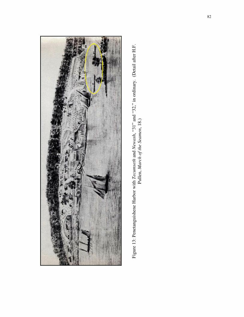
82
Fig
ure
13
: P
enet
ang
uis
hen
e H
arb
or
wit
h T
ecu
mse
th a
nd
New
ash
, “3
1”
and
“3
2,”
in
ord
inar
y. (
Det
ail
afte
r H
.F.
Pu
llen
, M
arc
h o
f th
e S
eam
en, 1
8.)
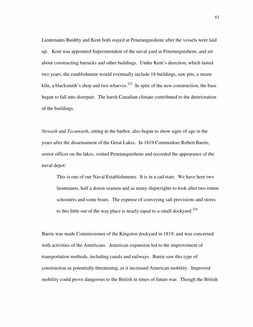
83
Lieutenants Bushby and Kent both stayed at Penetanguishene after the vessels were laid
up. Kent was appointed Superintendent of the naval yard at Penetanguishene, and set
about constructing barracks and other buildings. Under Kent’s direction, which lasted
two years, the establishment would eventually include 18 buildings, saw pits, a steam
kiln, a blacksmith’s shop and two wharves.227
In spite of the new construction, the base
began to fall into disrepair. The harsh Canadian climate contributed to the deterioration
of the buildings.
Newash and Tecumseth, sitting in the harbor, also began to show signs of age in the
years after the disarmament of the Great Lakes. In 1819 Commodore Robert Barrie,
senior officer on the lakes, visited Penetanguishene and recorded the appearance of the
naval depot:
This is one of our Naval Establishments. It is in a sad state. We have here two
lieutenants, half a dozen seamen and as many shipwrights to look after two rotten
schooners and some boats. The expense of conveying salt provisions and stores
to this little out of the way place is nearly equal to a small dockyard.228
Barrie was made Commissioner of the Kingston dockyard in 1819, and was concerned
with activities of the Americans. American expansion led to the improvement of
transportation methods, including canals and railways. Barrie saw this type of
construction as potentially threatening, as it increased American mobility. Improved
mobility could prove dangerous to the British in times of future war. Though the British
84
planned similar construction in Canada, they had yet to keep pace with the Americans.
Barrie wrote on the contrast in construction on either side of the border in 1819:
[T]hough I do not believe they contemplate an early rupture with us, they are
preparing for it – we too have Plans of Forts, Canals, and Roads drawn out on
our maps, but not a spade is employed on the Canals so long talked of – and little
done either to the Forts or Roads – in fact we seem to be laying on our Oars.”229
For a brief period from 1819 to 1822, the Royal Navy seemed once again interested in
maintaining a war-ready fleet. In 1819 the two hulls sitting in Penetanguishene harbor
were surveyed, and the expense of repairing them calculated. A vessel was needed to
transport troops from Penetanguishene to Drummond Island. Newash and Tecumseth
both bore the effects of dry rot in many of their timbers, including key structural
members.230
The mast steps, deck beams, keelson, wales, bottom planking and parts of
the frames were rotten.231
Tecumseth underwent repairs and was outfitted to sail once
more, albeit only briefly. Newash was to be repaired as well, after work was completed
on Tecumseth,232
but it is unlikely that this work transpired.
The costs and time involved in maintaining and repairing the aging vessels were too
much for the small establishment. In 1821, Newash was used as the site of a reception
for Lieutenant Governor Gore,233
but this was likely her last official duty. The following
year, the Admiralty once again ordered that the lake establishments be reduced and

85
officers returned from foreign posts, which Canada was considered.234
Lieutenant Henry
Kent returned to England in 1822, ten years after he had left in H.M.S. Fantome.235
By the mid-1820s, Newash and Tecumseth were rotten and sinking. Green, unseasoned
wood had been used in their construction, allowing Robert Moore and his shipwrights to
quickly deliver seaworthy vessels, but this sort of timber also shortened the life spans of
the ships. The same fate befell the other ships that had been built at the end of the war.
A survey conducted in 1827 noted that both vessels at Penetanguishene were
“completely rotten…sunk,” and that Newash was “on the beach.”236
In 1831, the two hulls were among a list of naval stores to be auctioned off at Hollands
Landing and Penetanguishene. Also listed were the smaller vessels Bee, Mosquitoe and
Wasp as well as several of the establishment’s boats and batteaux.237
The auctions were
held in March 1832, but neither Newash nor Tecumseth found a buyer, and instead
remained at their watery berths. Confiance and Surprize had also sunk in the harbor by
this time.
As the second quarter of the 19th century wore on, the British began to give up their
strongholds in Canada and reduced their armed forces across the country. Like the
establishment at Penetanguishene, the other depots on Lakes Erie and Huron became
unnecessary, and fell into disrepair as well. A flood in 1827 washed away the wharf and
86
four buildings at Grand River, effectively destroying the depot.238
After the sale of
stores and ships, the establishment at Penetanguishene was formally closed in 1834.239
Kingston remained a naval dockyard and depot in the post-war years, though its role
diminished until the establishment closed in 1834.240
Barrie was Commissioner of the
dockyard for the last 15 years of its existence, and kept many of the buildings in good
repair. Today, Kingston is home to the Royal Military College of Canada, on the ground
of the former Royal Navy establishments, and the city is considered the birthplace of the
Canadian Navy.
The Rush-Bagot Agreement has been altered somewhat since its original conception.
Both the United States and Canada use sites on the lakes, like the Royal Military College
of Canada, as training centers for naval personnel. Coast Guard stations have also been
set up on both sides of the border, but serve as bases for security and law enforcement,
rather than military posts. Until 2001, the majority of Coast Guard vessels were
unarmed, in compliance with the treaty. After September 2001, the United States Coast
Guard sought to equip several vessels on the lakes with large caliber weapons, as a
measure of national security. Since this was for policing and peacekeeping purposes,
Canada conceded to the armament in 2003.241
There are no standing navies on the Great
Lakes.

87
CHAPTER IX
ARCHAEOLOGICAL AND HISTORICAL RESEARCH
The sunken relics of the War of 1812 were not lost to local memory; fascination with the
War of 1812 preserved oral histories of the conflict into the 20th century. Anniversaries
of particular battles and a rebirth of interest in the 1920s and 1930s led to the relocation
and recovery of some vessels.242
In 1927, the wreck of H.M. Schooner Nancy was
recovered and put on display in Wasaga Beach, Ontario. Four vessels were rumored to
be located in Penetanguishene harbor; locals claimed that the hulls of Confiance and
Surprize were sunk at the west side of the harbor while another two wrecks, thought to
be Newash and Tecumseth, could be found near Magazine Island.
In 1933 the town of Penetanguishene sponsored a recovery in which salvers “floated the
wreck which we had seen in Colborne Basin [part of Penetanguishene harbor] across the
harbor to the town dock and placed its picked bones in the town park.”243
Local
historians suspected that the wreck was the American-built schooner Scorpion, a
participant in the Battle of Lake Erie that was captured by the British in 1814 and
renamed Confiance. The wooden remains attracted visitors and vandals alike, and over
time, the hull was pillaged: “much of it…disappeared, being transformed into chairs,
desks, gavels, walking canes, candlesticks, picture frames and other ‘souvenirs of the
Scorpion’.”244
In fact, the wreck pillaged by souvenir hunters was too small to be
Scorpion. Historian C.H.J. Snider later identified it as Scorpion’s smaller counterpart,
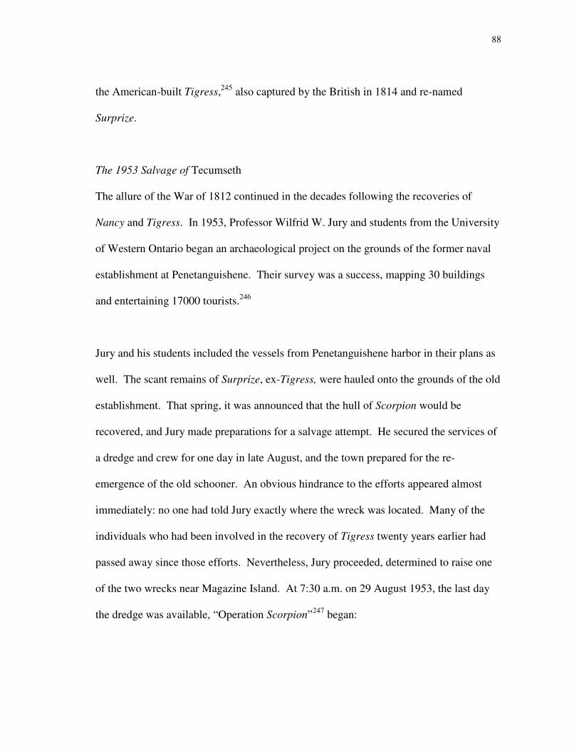
88
the American-built Tigress,245
also captured by the British in 1814 and re-named
Surprize.
The 1953 Salvage of Tecumseth
The allure of the War of 1812 continued in the decades following the recoveries of
Nancy and Tigress. In 1953, Professor Wilfrid W. Jury and students from the University
of Western Ontario began an archaeological project on the grounds of the former naval
establishment at Penetanguishene. Their survey was a success, mapping 30 buildings
and entertaining 17000 tourists.246
Jury and his students included the vessels from Penetanguishene harbor in their plans as
well. The scant remains of Surprize, ex-Tigress, were hauled onto the grounds of the old
establishment. That spring, it was announced that the hull of Scorpion would be
recovered, and Jury made preparations for a salvage attempt. He secured the services of
a dredge and crew for one day in late August, and the town prepared for the re-
emergence of the old schooner. An obvious hindrance to the efforts appeared almost
immediately: no one had told Jury exactly where the wreck was located. Many of the
individuals who had been involved in the recovery of Tigress twenty years earlier had
passed away since those efforts. Nevertheless, Jury proceeded, determined to raise one
of the two wrecks near Magazine Island. At 7:30 a.m. on 29 August 1953, the last day
the dredge was available, “Operation Scorpion”247
began:
89
Surrounded by an armada of small craft armed with cameras, flashlights,
microphones and equipment for speech-making and broadcasting, the dredge
plunged its steel-toothed clamshell bucket into a buoyed area a hundred yards
[91.46 m] from the bank, where the water was 15 feet [4.57 m] deep. A pause
while the steel teeth crunched like fangs on a bone, and up rose the bucket,
spewing jets of water, with a tapered black timber in its jaws. Motor horns
among the growing gallery of automobiles and spectators lining the foreshore
‘sounded a peal of warlike glee’ as the derrick arm swung and the opening
bucket dropped the timber on the dredge’s deck. Next was brought up a shorter
mass of blackened oak, with a stout chain attached. This the ‘experts,’ pale
augurs muttering low, pronounced a shank-painter, and none gainsaid their word
– not even when murmuring, ‘Newash or Tecumseth,’ they diagnosed the next lot
of oak and ironwork as the port forechains, waterways and channel. The pile of
dripping wood and rusted iron grew on the dredge deck until both bows of the
wreck had been demolished piecemeal, and the water was opaque with disturbed
silt. Still the ship had not been budged.248
Jury and his crew worked late into the evening, until the remains were wrenched from
their grave and hauled onshore (fig. 14). Several timbers had been dislodged from their
original places on the hull. Twelve round shot were found, cleaned, and emblazoned
with the name “Scorpion.”249
The wreck was examined by a number of experts250
who
all reached the same conclusion. The wreck was certainly not Scorpion; it was too large.
90
Figure 14: Tecumseth on the beach in Penetanguishene, 1953.
(Photo: John R. Stevens.)
91
Dimensions of the hull corresponded nearly exactly with a draft of two schooners
constructed in 1815: Tecumseth and Newash.
The wreck was specifically identified as H.M. Schooner Tecumseth, by evidence of the
rig. Three chainplates were recovered, indicating that the mast had three shrouds,
precisely as shown in the drawing. In addition, though the foremast step had
disappeared, bolts remained as testament to its location, which was far forward in the
bow.251
As Newash had been re-rigged as a brigantine and her foremast moved, the
foremast step would not have been in the same location as that in the draft.
Thus identified, the skeletal vessel was labeled and displayed. Archaeological work and
reconstruction continued at the former naval depot at Penetanguishene, and a museum
called Discovery Harbor (Havre de la Découverte) was established on the grounds. The
museum is home to two replica schooners, Tecumseth and Bee, which were
reconstructed on the basis of archaeological and historical evidence and sail the waters
of Penetanguishene Bay and beyond.
Early Publications
A photographer from Life magazine recorded the salvage in Penetanguishene, and an
article appeared in the publication shortly afterwards. Soon afterwards, experts on Great
Lakes vessels and other relevant topics, including historians C.H.J. Snider, Rowley
Murphy and John R. Stevens, visited the hull, helped identify the wreck and published

92
scholarly works on the vessel. Snider featured the vessel in his “Schooner Days”
column, published in the Toronto Evening Telegram.252
Murphy published
“Resurrection at Penetanguishene” in Inland Seas in 1954. He described the salvage and
illustrated the evidence that allowed the remains to be identified as Tecumseth. Stevens
prepared “The History of H.M. Armed Schooner Tecumseth.” In 1961, Stevens’ work
was printed along with Rear Admiral H.F. Pullen’s “The March of the Seamen.”
Together, Stevens’ and Pullen’s work presents a detailed view of the vessels. Pullen
concentrated his historical investigations on a naval uniform button found “between the
planking and the ceiling” of the ship.253
Based on the particular design on the face of
this button, Pullen traced it to the seamen who had traveled overland from New
Brunswick to Kingston in 1814, possibly even Lieutenant Henry Kent himself. Stevens
discussed the naval architecture of the schooner in his publication and drafted a number
of views of the hull, including a body plan, midship section, inboard profile, planking
expansion, a redrafting of Moore’s original construction design and a rigging plan.254
1970s Examination and Conservation Efforts
With the hull removed from Penetanguishene harbor, the archaeological remains of
Tecumseth were available for study. The shelter of Discovery Harbour (Havre de la
Découverte) protected the hull from the vandalism that had nearly destroyed Tigress, but
the remains were still subjected to the elements. In October 1976 Charles Hett, a
conservator, visited the wrecks in Penetanguishene. Hett examined the wooden remains
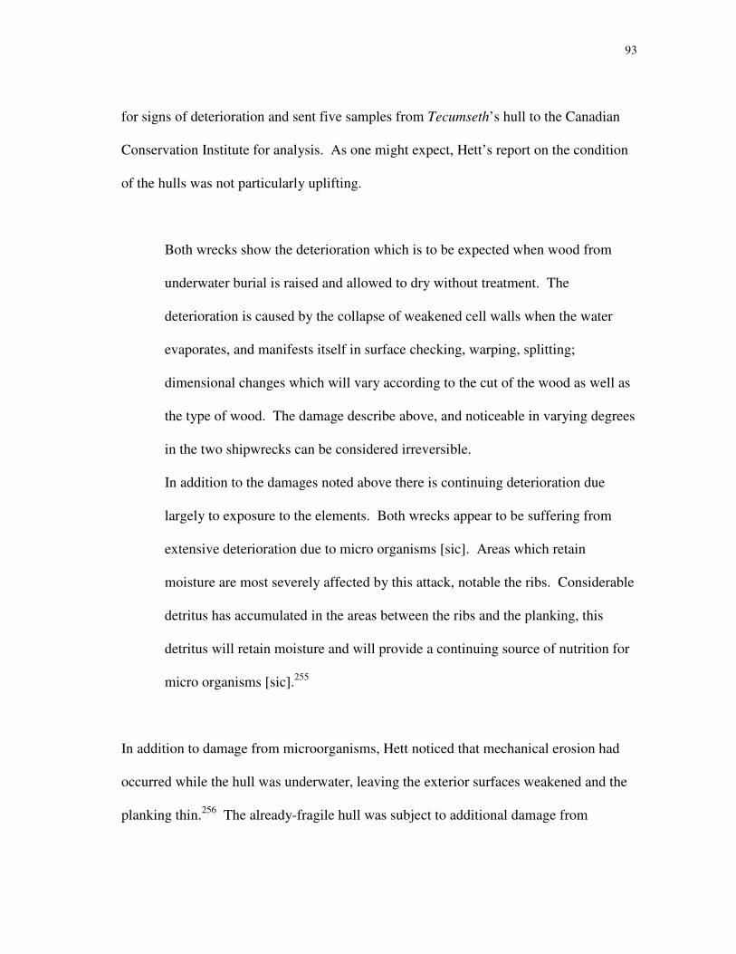
93
for signs of deterioration and sent five samples from Tecumseth’s hull to the Canadian
Conservation Institute for analysis. As one might expect, Hett’s report on the condition
of the hulls was not particularly uplifting.
Both wrecks show the deterioration which is to be expected when wood from
underwater burial is raised and allowed to dry without treatment. The
deterioration is caused by the collapse of weakened cell walls when the water
evaporates, and manifests itself in surface checking, warping, splitting;
dimensional changes which will vary according to the cut of the wood as well as
the type of wood. The damage describe above, and noticeable in varying degrees
in the two shipwrecks can be considered irreversible.
In addition to the damages noted above there is continuing deterioration due
largely to exposure to the elements. Both wrecks appear to be suffering from
extensive deterioration due to micro organisms [sic]. Areas which retain
moisture are most severely affected by this attack, notable the ribs. Considerable
detritus has accumulated in the areas between the ribs and the planking, this
detritus will retain moisture and will provide a continuing source of nutrition for
micro organisms [sic].255
In addition to damage from microorganisms, Hett noticed that mechanical erosion had
occurred while the hull was underwater, leaving the exterior surfaces weakened and the
planking thin.256
The already-fragile hull was subject to additional damage from
94
environmental effects, and Hett recommended that some type of structure be built over
both hulls, to protect them from further damage.
Hett found traces of preliminary conservation efforts:
Application of a commercial synthetic resin…[has] been made to the
wood and metal parts…This material is visible as a glossy varnish in the
iron, but is not visible on the surface of the wood. It is impossible to see
whether this has achieved any useful purpose, unknown materials should
not be employed for consolidation; in general they cause more problems
than they solve.257
As a result of Hett’s recommendations, both hulls were moved to a permanent display
area on the grounds of the museum. The remains of Tecumseth, being more substantial
and in better condition than that of Tigress, are more prominently displayed.
1997 – 1998 Archaeology
Although Jury’s efforts in 1953 have made the remains of H.M. Schooner Tecumseth
readily accessible for study by nautical archaeologists and the non-diving public alike,
modern archaeological techniques are far superior to those used in the salvage. The hull
certainly suffered tremendously in the dredge’s jaws and evidence of the vessel’s design
and construction was obliterated. As nautical archaeologists can attest, much more
information can be gathered about a shipwreck from studying it in situ, or by careful
excavation and recording, than by simply removing the wreckage off the bottom. The

95
timbers have also suffered from a minimal amount of preservation treatment and
continual exposure to environmental effects.
While studies undertaken shortly after Jury’s salvage analyzed the remains and
documented the overall history of the vessel, Tecumseth was not subject to modern
archaeological study. As part of a comprehensive Texas A&M University program to
investigate War of 1812-era shipwrecks in the Great Lakes, Tecumseth was visited by a
team of student archaeologists, led by graduate student Erich Heinold, over two weeks in
June 1997. The following summer Newash was surveyed in situ at the bottom of
Penetanguishene harbor. Dimensions were taken of all accessible timbers, using
measuring tapes and goniometers. Significant details of the hulls were drawn, to gain a
better understanding of the precise methods used in constructing the two ships and wreck
plans were made of the existing timbers of both hulls.
In addition to the archaeological study, Heinold searched for documentary evidence of
the two vessels. Because the ships had served in the Royal Navy, many Admiralty
records survive of their sailing careers and the events of the time; a number are currently
held in the Library and Archives of Canada in Ottawa.
Although Heinold compiled a large amount of archival and field documentation and
made detailed wreck plans (figs. 15 and 16), no final project or publication was created.
Many of the field notes and copies of Admiralty documents made during the

96
Fig
ure
15
: W
reck
pla
n o
f N
ewa
sh r
emai
ns.
(D
raw
ing
: E
rich
Hei
no
ld, “H
.M.
Sch
oo
ner
New
ash
Wre
ck P
lan
,” P
riv
ate
Co
llec
tio
n o
f K
evin
J. C
rism
an.)
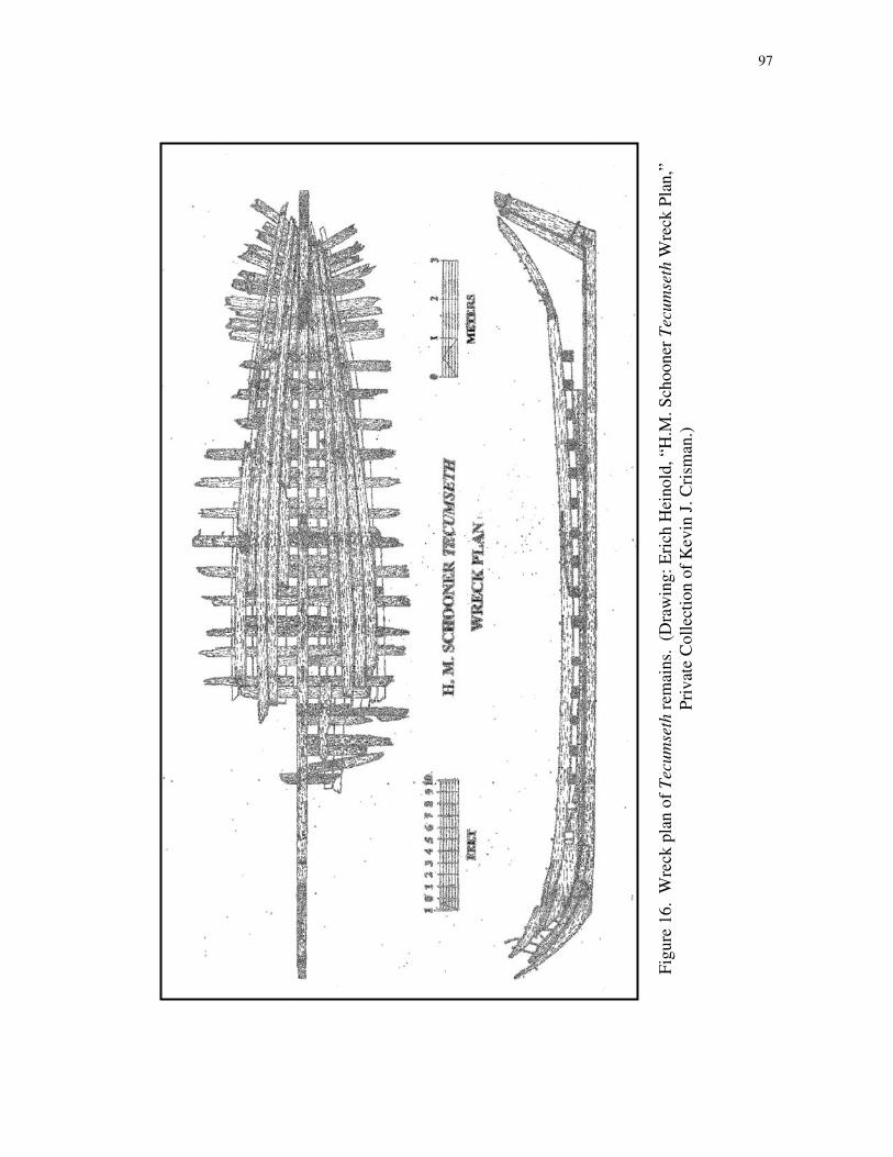
97
Fig
ure
16
. W
reck
pla
n o
f T
ecu
mse
th r
emai
ns.
(D
raw
ing
: E
rich
Hei
no
ld, “H
.M. S
cho
on
er T
ecu
mse
th W
reck
Pla
n,”
Pri
vat
e C
oll
ecti
on
of
Kev
in J
. C
rism
an.)
98
archaeological investigations are held in the collections of Dr. Kevin Crisman, professor
of Nautical Archaeology at Texas A&M University.
2007 – 2008 Investigations
Because a final publication had yet to be created, additional research was conducted in
preparation for the current project during the summers of 2007 and 2008. The author
made two trips to Penetanguishene, documenting specific details of Tecumseth each
time. Historical records in the Bayfield Room at the Penetanguishene Public Library
were consulted, and microfilm and transcribed documents at the Library and Archives of
Canada were analyzed for pertinent information.
While preparing this hull and rigging analysis, the author had the opportunity to discuss
matters of history, shipbuilding and seamanship with captains of modern re-
interpretations of contemporary vessels including the U.S. Brig Niagara and the topsail
schooner Pride of Baltimore II. Both vessels are reconstructions of War of 1812-era
ships, and the captains contributed insights into potential sailing characteristics of
contemporary sailing vessels.

99
CHAPTER X
ARCHAEOLOGICAL EVIDENCE OF THE SCHOONERS’ CONSTRUCTION
The remains of Tecumseth have been examined and recorded on several occasions since
her removal from Penetanguishene Bay. In spite of the dry rot which has affected the
hull since Jury’s salvage, the remains kept their form remarkably well. The remaining
portions comprised the lowest elements of the hull, including parts of the keel, keelson,
frames, outer planking, interior or ceiling planking, sternpost and stem. Because the
ceiling planking was still in place during archaeological investigations in 1997-98 and
2007-08, some of the details of the hull construction were inaccessible. Some other
features of the remains were obscured due to their location within the structure housing
hull. The two schooners were built using feet and inches, these units have been used to
describe the hull features. Metric equivalents are also provided.
Newash was examined and documented in 1998; the remains were submerged in
approximately 6 to 12 feet (1.83 m to 3.66 m) of water, listing to the port side.
Archaeological permits granted to Heinold and his team did not allow disturbance of any
sediments on or around the remains of Newash, limiting the survey to those timbers that
remained exposed above the harbor bottom. Zebra mussels covered some wreck
features, particularly iron fasteners, obscuring details as well. The wreck site was
surveyed and timbers were documented over approximately two weeks in July 1998.
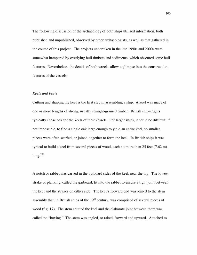
100
The following discussion of the archaeology of both ships utilized information, both
published and unpublished, observed by other archaeologists, as well as that gathered in
the course of this project. The projects undertaken in the late 1990s and 2000s were
somewhat hampered by overlying hull timbers and sediments, which obscured some hull
features. Nevertheless, the details of both wrecks allow a glimpse into the construction
features of the vessels.
Keels and Posts
Cutting and shaping the keel is the first step in assembling a ship. A keel was made of
one or more lengths of strong, usually straight-grained timber. British shipwrights
typically chose oak for the keels of their vessels. For larger ships, it could be difficult, if
not impossible, to find a single oak large enough to yield an entire keel, so smaller
pieces were often scarfed, or joined, together to form the keel. In British ships it was
typical to build a keel from several pieces of wood, each no more than 25 feet (7.62 m)
long.258
A notch or rabbet was carved in the outboard sides of the keel, near the top. The lowest
strake of planking, called the garboard, fit into the rabbet to ensure a tight joint between
the keel and the strakes on either side. The keel’s forward end was joined to the stem
assembly that, in British ships of the 19th
century, was comprised of several pieces of
wood (fig. 17). The stem abutted the keel and the elaborate joint between them was
called the “boxing.” The stem was angled, or raked, forward and upward. Attached to

101
the stem and also to the keel was a timber called the “gripe.” The gripe projected
downward from the stem, a feature thought to increase a ship’s windward ability.259
The
sternpost was attached at the after end of the keel, often at an angle. A mortise cut into
the top of the keel accommodated a corresponding tenon in the bottom of the sternpost.
The rakes of the sternpost and stem extended the vessel’s overall length.
Tecumseth’s keel was made of one piece of white oak260
and measured 55 feet 9.75
inches (17.02 m) long.261
It was 10 inches (25.41 cm) sided, with a molded depth of 13
inches (33.03 cm). Eleven inches (27.95 cm) of the keel projected below the rabbet.
Newash’s keel was only exposed enough to obtain adequate measurements near the bow.
Here, the sided dimensions ranged from 8 inches (20.32 cm) to 10 inches (25.41 cm),
Figure 17: Bow assembly of large contemporary vessels.
(Detail from C. Nepean Longridge, Anatomy of
Nelson’s Ships, 14.)

102
with a molded dimension ranging from 13.75 inches (34.93 cm) to 16.5 inches (41.91
cm). Many gaps and grooves in this timber were filled in with sediment.
A false keel may have been attached underneath the keel, both to add lateral resistance
and to serve as a sacrificial piece of wood, which would have protected the keel should
the vessel run aground.262
No false keel survives, but archaeologists observed two
grooves or channels along the bottom of Newash’s keel, which may testify to its
existence. Field notes from the 1998 season indicated that several of the iron bolts found
in Newash’s keel extended beyond the range of the keel, and may have been used to
attach a false keel, which had broken or eroded away.
Tecumseth’s stem was attached to the keel with a boxing scarf,263
a complex joint that
indicates the significance of the union between the keel and stem (fig. 18). Without a
strong connection at this place, the hull’s structural integrity might have been
compromised. With the overlying timbers still in place, it was difficult to identify
Tecumseth’s boxing scarf. Viewed from the side, a boxing scarf looks like a simple
Figure 18: Boxing scarf. (Detail from J.
Richard Steffy, Wooden Ship Building,
292, fig. G-11b.)
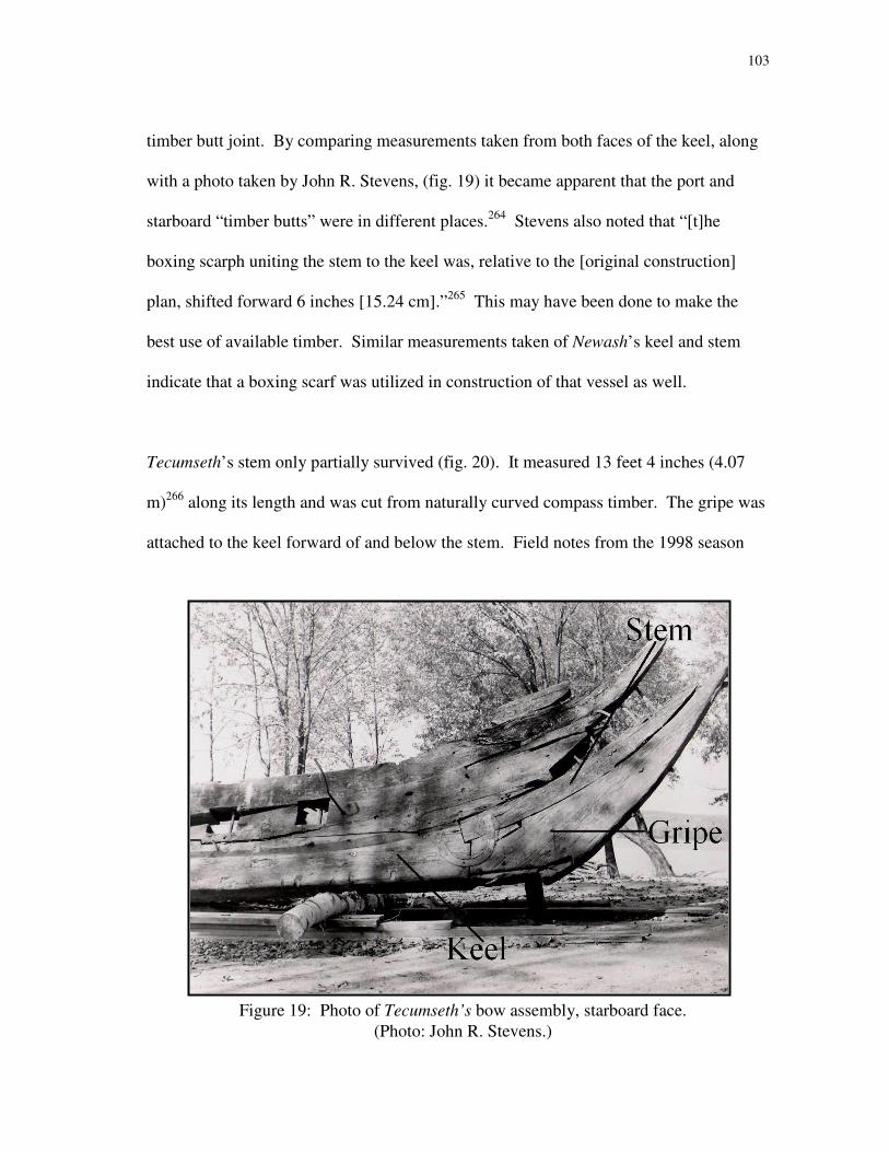
103
timber butt joint. By comparing measurements taken from both faces of the keel, along
with a photo taken by John R. Stevens, (fig. 19) it became apparent that the port and
starboard “timber butts” were in different places.264
Stevens also noted that “[t]he
boxing scarph uniting the stem to the keel was, relative to the [original construction]
plan, shifted forward 6 inches [15.24 cm].”265
This may have been done to make the
best use of available timber. Similar measurements taken of Newash’s keel and stem
indicate that a boxing scarf was utilized in construction of that vessel as well.
Tecumseth’s stem only partially survived (fig. 20). It measured 13 feet 4 inches (4.07
m)266
along its length and was cut from naturally curved compass timber. The gripe was
attached to the keel forward of and below the stem. Field notes from the 1998 season
Figure 19: Photo of Tecumseth’s bow assembly, starboard face.
(Photo: John R. Stevens.)

104
indicate that a groove was cut into the forward end of the keel, giving it a “U” shape. 267
This groove may have accommodated a tenon in the after end of the gripe. Unlike the
stem, Tecumseth’s gripe was not cut from compass timber but instead shaped from
straight-grained timber, with the grain running at an angle of approximately 135º to the
keel. Only the lower 8 feet 9 inches (2.67 m)268
of Tecumseth’s gripe remained, and it
was 10.00 inches (27.94 cm) sided and 18.25 inches (46.37 cm) molded at its greatest
depth. The total projection of the stem and gripe below and forward of the rabbet is
25.00 inches (63.52 cm). The gripe was somewhat fuller than the construction draft
indicated, possibly as a result of the shift in the boxing scarf.269
As previously
discussed, the projection of the gripe increased the ship’s lateral resistance and her
ability to sail close to the wind.
Figure 20: Drawing of Tecumseth’s bow assembly, port face. Not to scale.
(Drawing: Bryan Atchison, “Stem Assembly (Port),” 19 June 1997. Private
Collection of Kevin J. Crisman.)
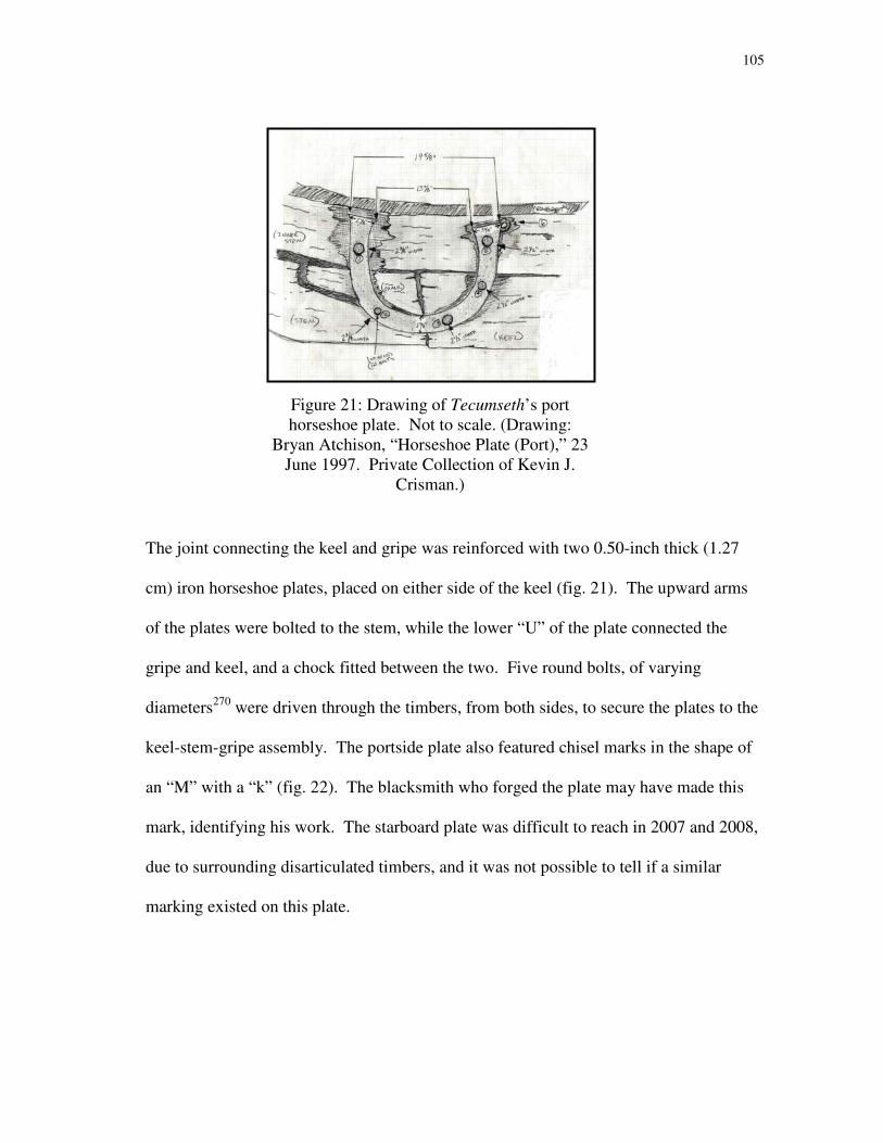
105
The joint connecting the keel and gripe was reinforced with two 0.50-inch thick (1.27
cm) iron horseshoe plates, placed on either side of the keel (fig. 21). The upward arms
of the plates were bolted to the stem, while the lower “U” of the plate connected the
gripe and keel, and a chock fitted between the two. Five round bolts, of varying
diameters270
were driven through the timbers, from both sides, to secure the plates to the
keel-stem-gripe assembly. The portside plate also featured chisel marks in the shape of
an “M” with a “k” (fig. 22). The blacksmith who forged the plate may have made this
mark, identifying his work. The starboard plate was difficult to reach in 2007 and 2008,
due to surrounding disarticulated timbers, and it was not possible to tell if a similar
marking existed on this plate.
Figure 21: Drawing of Tecumseth’s port
horseshoe plate. Not to scale. (Drawing:
Bryan Atchison, “Horseshoe Plate (Port),” 23
June 1997. Private Collection of Kevin J.
Crisman.)
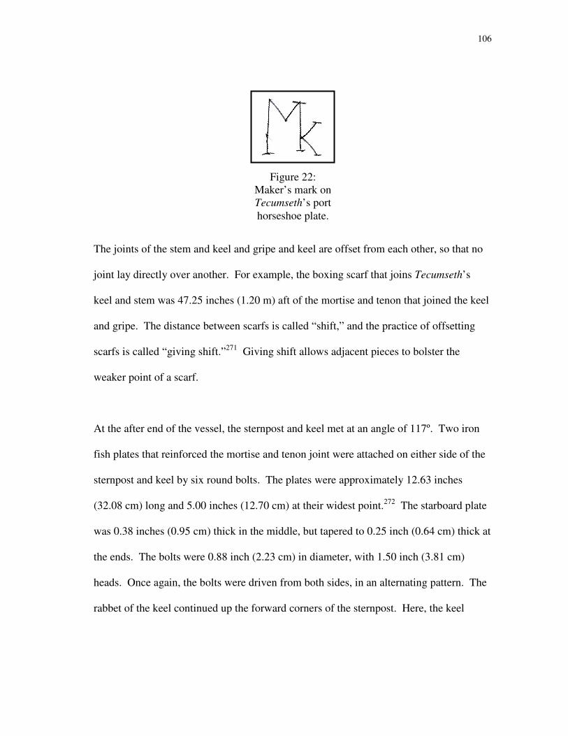
106
Figure 22:
Maker’s mark on
Tecumseth’s port
horseshoe plate.
The joints of the stem and keel and gripe and keel are offset from each other, so that no
joint lay directly over another. For example, the boxing scarf that joins Tecumseth’s
keel and stem was 47.25 inches (1.20 m) aft of the mortise and tenon that joined the keel
and gripe. The distance between scarfs is called “shift,” and the practice of offsetting
scarfs is called “giving shift.”271
Giving shift allows adjacent pieces to bolster the
weaker point of a scarf.
At the after end of the vessel, the sternpost and keel met at an angle of 117º. Two iron
fish plates that reinforced the mortise and tenon joint were attached on either side of the
sternpost and keel by six round bolts. The plates were approximately 12.63 inches
(32.08 cm) long and 5.00 inches (12.70 cm) at their widest point.272
The starboard plate
was 0.38 inches (0.95 cm) thick in the middle, but tapered to 0.25 inch (0.64 cm) thick at
the ends. The bolts were 0.88 inch (2.23 cm) in diameter, with 1.50 inch (3.81 cm)
heads. Once again, the bolts were driven from both sides, in an alternating pattern. The
rabbet of the keel continued up the forward corners of the sternpost. Here, the keel
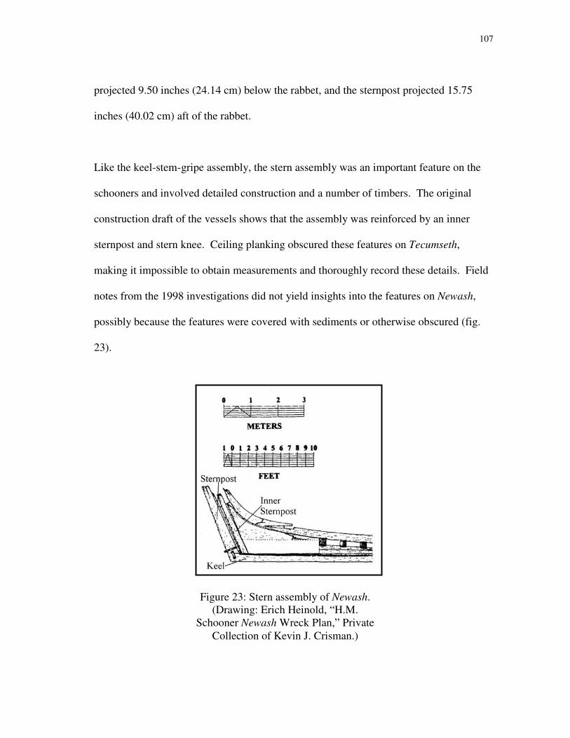
107
projected 9.50 inches (24.14 cm) below the rabbet, and the sternpost projected 15.75
inches (40.02 cm) aft of the rabbet.
Like the keel-stem-gripe assembly, the stern assembly was an important feature on the
schooners and involved detailed construction and a number of timbers. The original
construction draft of the vessels shows that the assembly was reinforced by an inner
sternpost and stern knee. Ceiling planking obscured these features on Tecumseth,
making it impossible to obtain measurements and thoroughly record these details. Field
notes from the 1998 investigations did not yield insights into the features on Newash,
possibly because the features were covered with sediments or otherwise obscured (fig.
23).
Figure 23: Stern assembly of Newash.
(Drawing: Erich Heinold, “H.M.
Schooner Newash Wreck Plan,” Private
Collection of Kevin J. Crisman.)
108
The after face of the sternpost was beveled on each side to allow the rudder, which was
hung by pintles and gudgeons, to swing freely. Two of Tecumseth’s gudgeons survived,
bolted to the sternpost and adjacent planking. Both gudgeons were placed at a 90º angle
to the sternpost’s after face. The lower gudgeon embraced the sternpost with arms that
were 24.75 inches (62.88 cm) in length, and secured with four round bolts driven from
alternating sides. The gudgeon arms were 0.25 inches (0.64 cm) thick at their forward
ends and 0.50 inches (1.27 cm) thick at the aft face of the sternpost. The upper gudgeon
was much shorter than the lower one, with arms measuring 11 inches (27.95 cm) long.
The arms were attached to the sternpost with three round bolts, of 0.88-inch (2.22 cm)
diameter. The upper gudgeon was slightly thicker, measuring 0.38 inches (0.95 cm) at
its forward end and 0.50 inch (1.27 cm) at the aft face of the sternpost. The gudgeons
were shaped to accommodate a 2-inch (5.08 cm) diameter pintle, which was attached to
the rudder. To support the weight of the rudder, both gudgeons were thicker around the
hole, measuring nearly 1 inch (2.54 cm) in thickness. Tecumseth’s gudgeons were
placed 6 feet 2 inches (1.88 m) apart. The site plan of Newash shows only one gudgeon,
since the extant remains of the sternpost are much shorter than Tecumseth’s surviving
sternpost.
Deadwood
After the keel and posts were raised, frames could be shaped, assembled and attached.
For increased strength, frames were sandwiched between two strong pieces of wood.
One such piece, called the rising deadwood, was placed on top of the keel, and notches
109
were cut into its upper surface to receive frames. The rising deadwood was not very
thick, only measuring 3 inches (7.62 cm) molded near the bow, where it was accessible.
Deadwood pieces were also placed in the bow and stern, both to strengthen the stem and
sternpost assemblies, and to offer better points of attachment for the narrow frames that
appear there.
The deadwood was shaped very precisely, so that it would lie in contact with the
adjacent pieces. When a timber was shaped in this way, it is called “faying.”273
In
Royal Navy ships of the Napoleonic era, an inner stem was fayed to fit directly atop the
stem. Tecumseth’s stem assembly was also reinforced with an apron, at the forward end
of the rising deadwood. The apron, stem, and other deadwood pieces were cut and
trimmed to fit closely to each other, and bolted securely together. Likewise, the
reinforcing pieces of the stern assembly, the inner sternpost and stern knee, were fayed
to fit tightly with one another. This created a solid mass of timber that strengthened
these critical areas of the hulls.
Frames
After the keels and posts were raised, frames were cut, shaped and assembled from
several short pieces of wood. Each square frame was made with a single timber that
crossed over the keel, called a floor, and a series of futtocks extending up the sides of the
hull. On Tecumseth and Newash, the floors were set into notches cut in the rising
deadwoods atop the keels with the lowest, or first, futtocks placed on the forward or after

110
side of the floors. On the two hulls the first futtocks were placed aft of the floors
forward of the midship frame, the widest in the hull, while in the after part the first
futtocks were placed forward of the floors. The rising deadwood was not notched for the
first futtocks; rather, the heels of the first futtocks were shaped to fit over one side of the
deadwood. The port and starboard first futtocks met at the vessels’ centerlines, but did
not cross them.
Because the interior and exterior planking remained intact, examining Tecumseth’s
frames and futtocks proved difficult. In some areas, the planking had been eroded or
torn away and it was possible to measure either the frames themselves or the notches cut
to receive them. From these, it was possible to obtain averages for the dimensions of the
frames and futtocks. They averaged 9.10 inches (23.12 cm) molded and 10.00 inches
(25.41 cm) sided.274
Early observations of Tecumseth noted that the frames were placed
on 30-inch (79.22 cm) centers.275
Field notes of Heinold’s observations indicate that
there were 16 full, or square, frames along the length of the vessel, with an indeterminate
number of cant frames in the bow and half-frames in the stern.276
A sample taken from
one “rib” in 1976 was identified as white oak.277
John R. Stevens, who examined the
ship in the 1950s, noted that some of the frames were made of pine.278
It is possible that
these pine frame timbers were replacements added when the schooner was refitted in
1819.
111
Second, third and fourth futtocks were placed at the ends of the floors and first futtocks
to compete the rest of the frames. From the site plan of Newash, it is evident that the
floors were roughly the same length. To avoid a situation where the bottom part of the
vessel was not attached to the top, scarfs between floors and futtocks gave shift to each
other. The floors and futtocks were attached to each other with iron spikes and treenails.
Keelsons, Stemsons and Sternsons
The floors were secured in place by the addition of a keelson, a longitudinal member
lying on top of the keel and frames. Notches were cut into the underside of the keelson
to fit over the floors. The forward end of the keelson was scarfed to another longitudinal
member called a stemson while a sternson was scarfed to its after end.
The sternson, like most of the stern assembly, was not visible on Tecumseth because of
surviving ceiling planking. The keelson was evident, and was recorded during Heinold’s
1997 field season, and again in 2008. It measured 9.25 inches (23.50 cm) sided, had an
average molded depth of 11.00 inches (27.95 cm) and was fastened to the floors with
1.13-inch (2.86 cm) diameter iron bolts. Newash’s keelson was made of two separate
timbers; hook scarfs were used to join the pieces of the keelsons on both vessels (fig.
24). A sample taken from Tecumseth’s keelson was determined to be white oak.279
Tecumseth’s stemson was made of compass timber, with the grain running in a similar
direction to the stem. A plan view of the stemson shows that the timber used did not
have a smooth longitudinal grain (fig. 25); the use of this timber may demonstrate the

112
brief time in which the vessels were built, or the quality of locally-grown compass
timber available to the shipwrights in 1815.
Mast Steps
The stemson-keelson-sternson assembly supported the mast steps, which in turn
supported the masts. No evidence survives on either wreck of the foremast steps. The
mainmast steps on both Newash and Tecumseth do survive, however, in the form of
mortises cut into the top of the keelson. On the latter vessel, the mortise was found just
8.63 inches (21.91 cm) aft of a hook scarf that joins two pieces of Tecumseth’s keelson.
The mortise in Tecumseth’s keelson (fig. 26) measured 6.69 inches (16.99 cm) wide and
9.50 inches (24.14 cm) long. At the forward edge of the mortise, the keelson itself
measured 9.63 inches (24.45 cm) sided. The after surface of the mortise was cut at an
angle, which was necessary to provide support for the raked mast. Extensive dry rot
Figure 24: Hook scarf in Tecumseth’s keelson. Not to scale. (Drawing: Erich
Heinold and Bryan Atchison, “Keelson Scarf (Port Side View),” 24 June 1997.
Private Collection of Kevin J. Crisman.)
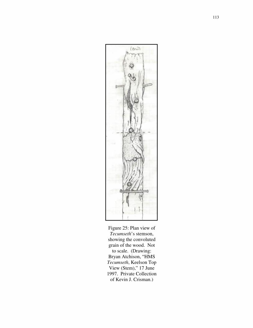
113
Figure 25: Plan view of
Tecumseth’s stemson,
showing the convoluted
grain of the wood. Not
to scale. (Drawing:
Bryan Atchison, “HMS
Tecumseth, Keelson Top
View (Stem),” 17 June
1997. Private Collection
of Kevin J. Crisman.)
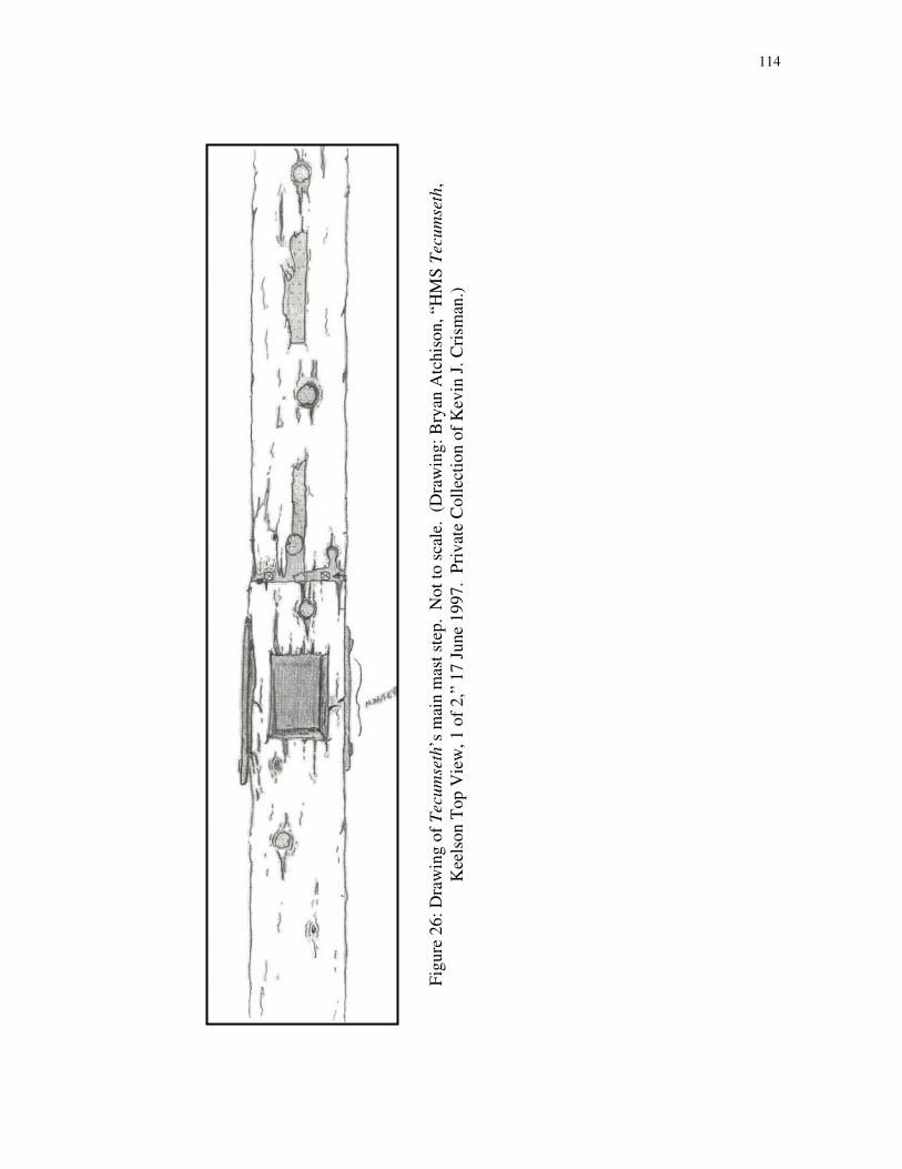
114
Fig
ure
26
: D
raw
ing
of
Tecu
mse
th’s
mai
n m
ast
step
. N
ot
to s
cale
. (
Dra
win
g:
Bry
an A
tch
iso
n, “H
MS
Tec
um
seth
,
Kee
lso
n T
op
Vie
w, 1
of
2,”
17
Ju
ne
19
97
. P
riv
ate
Co
llec
tio
n o
f K
evin
J.
Cri
sman
.)
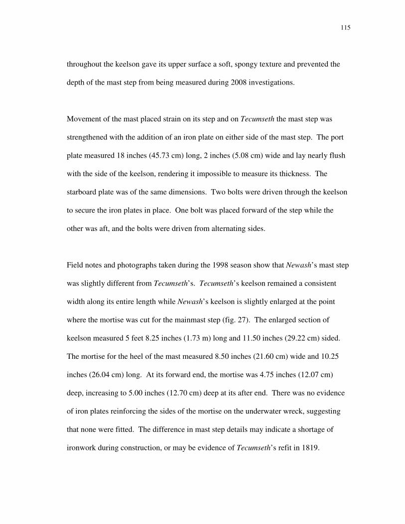
115
throughout the keelson gave its upper surface a soft, spongy texture and prevented the
depth of the mast step from being measured during 2008 investigations.
Movement of the mast placed strain on its step and on Tecumseth the mast step was
strengthened with the addition of an iron plate on either side of the mast step. The port
plate measured 18 inches (45.73 cm) long, 2 inches (5.08 cm) wide and lay nearly flush
with the side of the keelson, rendering it impossible to measure its thickness. The
starboard plate was of the same dimensions. Two bolts were driven through the keelson
to secure the iron plates in place. One bolt was placed forward of the step while the
other was aft, and the bolts were driven from alternating sides.
Field notes and photographs taken during the 1998 season show that Newash’s mast step
was slightly different from Tecumseth’s. Tecumseth’s keelson remained a consistent
width along its entire length while Newash’s keelson is slightly enlarged at the point
where the mortise was cut for the mainmast step (fig. 27). The enlarged section of
keelson measured 5 feet 8.25 inches (1.73 m) long and 11.50 inches (29.22 cm) sided.
The mortise for the heel of the mast measured 8.50 inches (21.60 cm) wide and 10.25
inches (26.04 cm) long. At its forward end, the mortise was 4.75 inches (12.07 cm)
deep, increasing to 5.00 inches (12.70 cm) deep at its after end. There was no evidence
of iron plates reinforcing the sides of the mortise on the underwater wreck, suggesting
that none were fitted. The difference in mast step details may indicate a shortage of
ironwork during construction, or may be evidence of Tecumseth’s refit in 1819.

116
Mast Section
A single fragment of a mast was found in the display with the hull of Tecumseth. The
piece of mast was 10 feet 11 inches (3.33 m) long, with a maximum diameter of 11.11
inches (28.23 cm). The mast was roughly hewn, with visible hatchet marks280
, and a
crude tenon at its heel. The tenon measured 8.56 inches (21.75 cm) at its maximum
length and 6.00 inches (15.24 cm) wide. What was presumed to be the after edge was
chamfered at an angle of 10º, evidence of a slight rake.
The difference between the tenon at the heel of this mast fragment and the size of the
mortise in the keelson could be explained by wear and deterioration over the course of
the vessel’s life. It is also possible that the tenon was deliberately made smaller than the
Figure 27: Detail of Newash’s main mast step, circled. (Detail from Erich Heinold,
“H.M. Schooner Newash Wreck Plan,” Private Collection of Kevin J. Crisman.)
117
mortise and was wedged into place with small pieces of wood. The small diameter of
the mast piece, however, raises some questions. If it belonged to Newash or Tecumseth,
it was far smaller than either of the masts shown in Robert Moore’s construction draft.
Moore shows a 19-inch (48.27 cm) diameter mast. It is true that masts often taper below
the mast partners, which support a mast at the deck level. The length of the surviving
mast piece, at nearly 11 feet (3.35 m), would reach beyond the mast partners of either
fore or main masts on Newash and Tecumseth. It is far more likely that this section of
mast is a part of the disarticulated remains of the schooner Surprize (ex-Tigress), which
share the small display structure with the hull of Tecumseth.
Pump Wells and Limber Holes
Inevitably, wooden ships leak. Though wood expands when it is saturated, tightening
planking seams, water still seeps into the hull. This water typically remains in the lowest
parts of the hull, and is called bilge water. Excess bilge water is expelled by the ship’s
pumps. Traditionally, such pumps were located near the main mast step. Two pump
wells were found on both Tecumseth and Newash, just aft and slightly outboard of the
main mast steps. The wells were for the placement of pump tubes, used to expel excess
bilge water from within the hull. The pump wells, as measured on the remains of
Newash, were 11 and 11.25 inches (27.95 cm and 28.58 cm) in diameter, and were
partially cut from the forward edge of one of the floors.
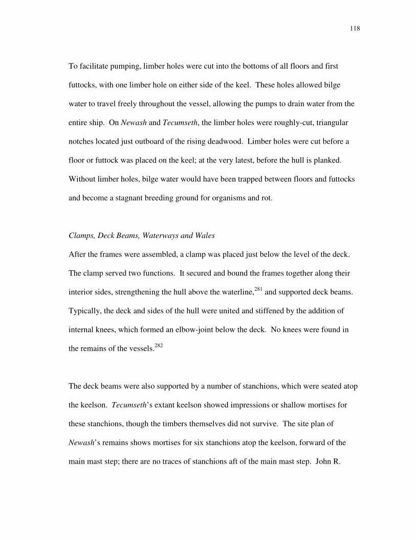
118
To facilitate pumping, limber holes were cut into the bottoms of all floors and first
futtocks, with one limber hole on either side of the keel. These holes allowed bilge
water to travel freely throughout the vessel, allowing the pumps to drain water from the
entire ship. On Newash and Tecumseth, the limber holes were roughly-cut, triangular
notches located just outboard of the rising deadwood. Limber holes were cut before a
floor or futtock was placed on the keel; at the very latest, before the hull is planked.
Without limber holes, bilge water would have been trapped between floors and futtocks
and become a stagnant breeding ground for organisms and rot.
Clamps, Deck Beams, Waterways and Wales
After the frames were assembled, a clamp was placed just below the level of the deck.
The clamp served two functions. It secured and bound the frames together along their
interior sides, strengthening the hull above the waterline,281
and supported deck beams.
Typically, the deck and sides of the hull were united and stiffened by the addition of
internal knees, which formed an elbow-joint below the deck. No knees were found in
the remains of the vessels.282
The deck beams were also supported by a number of stanchions, which were seated atop
the keelson. Tecumseth’s extant keelson showed impressions or shallow mortises for
these stanchions, though the timbers themselves did not survive. The site plan of
Newash’s remains shows mortises for six stanchions atop the keelson, forward of the
main mast step; there are no traces of stanchions aft of the main mast step. John R.

119
Fig
ure
28
: P
lan
vie
w o
f T
ecu
mse
th’s
dec
k b
eam
. N
ot
to s
cale
. (
Dra
win
g:
Bry
an A
tch
iso
n, “D
eck
Bea
m (
No
t to
Sca
le),
” 2
8 J
un
e 1
99
7. P
riv
ate
Co
llec
tio
n o
f K
evin
J. C
rism
an.)

120
Stevens observed that all of the deck beams between the masts were supported by
stanchions, except three. He proposed that the stanchions were evenly spaced except for
a gap where a hatch leading into the main cargo hold was placed. The beams adjacent to
this hatch may have required extra reinforcing, particularly since the two long guns were
placed on this area of the deck. Stevens also noted that the stanchions were “inclined so
that they would be perpendicular with the line of flotation.”283
To place the stanchions,
Stevens observed that “after their heads had been fitted in mortises in the [deck] beams,
[the stanchions] were driven into their steps through scores entering from abaft. The
scores were plugged to prevent the pillars from working out. One of the fillers was still
in position when I [Stevens] examined the wreck.”284
Several timbers on both wrecks have become dissociated from the rest of the hull. It is
often difficult to identify these detached timbers, as many factors can mask their original
purpose. One disarticulated timber was also found with the remains of Tecumseth
during the 1997 season. Roughly 6.25 inches (15.88 cm) square and nearly 9 feet 6
inches (2.90 m) long, the timber was identified as a deck beam (fig. 28). The timber had
two notches, both 11.00 inches (27.95 cm) wide; one measured 1.25 inches (3.18 cm)
deep and the other 0.75 inches (1.91 cm) deep. These notches may have been cut for
carlings, which ran longitudinally between deck beams and added strength and support
to the deck planking. The timber contained six spike holes and partial remains of five
spikes. A ring bolt and ring, was also found, attached to the beam.285

121
Figure 29: Drawing of disarticulated
timber from Newash, identified as a
clamp/waterway but possibly an
exterior plank with chainplates
attached. Not to scale. (Drawing:
Eric B. Emery, “Newash Project,
Clamp/Waterway Top View,” 15 – 16
July 1998. Private Collection of
Kevin J. Crisman.)
122
Another dissociated timber was found underwater near Newash in 1998 and identified as
part of a clamp/waterway assembly. This identification may not be correct. As
mentioned, the clamp joined the upper ends of the frames and supported deck beams;
atop the deck beams, deck planking was placed and a waterway ran along the edges of
the hull. The timber was partially buried in sediments, and consisted of fragments of
two separate timbers that remained connected by several bolts. The lower piece was
difficult to record due to the overlying sediments, but a top view of the upper timber was
produced (fig. 29). The timber measured 16 feet 3.50 inches (4.97 m) long, 6.50 inches
(16.51 cm) wide and 2.00 inches (5.08 cm) thick at its widest point.286
Several iron bolts
survive in conjunction with this piece; at least three have shaft diameters of 1 inch (2.54
cm).The disarticulated timbers may not be a clamp and waterway.
Observations made in 1953 noted that the interior of the vessel featured no knees, which
would have served as internal bracing pieces. Without knees, it is likely that the
shipwrights would have stiffened the shell of the hull with an enlarged clamp and
waterway assembly, probably with timbers larger than 2 inches (5.08 cm) thick. In a
reconstruction drawing of the midship section of Tecumseth, John R. Stevens illustrated
such an assembly, with an enlarged clamp and waterway but no internal knees (fig. 30).
In addition, three figure-of-eight shaped pieces are shown in the top view of the
disarticulated timber. The pieces appear to have one hole in either side. Unfortunately,
no mention of the material of these pieces was made in the field notes. The
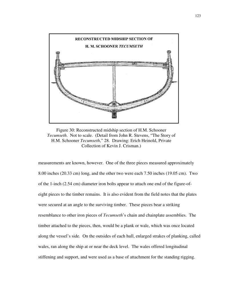
123
Figure 30: Reconstructed midship section of H.M. Schooner
Tecumseth. Not to scale. (Detail from John R. Stevens, “The Story of
H.M. Schooner Tecumseth,” 28. Drawing: Erich Heinold, Private
Collection of Kevin J. Crisman.)
measurements are known, however. One of the three pieces measured approximately
8.00 inches (20.33 cm) long, and the other two were each 7.50 inches (19.05 cm). Two
of the 1-inch (2.54 cm) diameter iron bolts appear to attach one end of the figure-of-
eight pieces to the timber remains. It is also evident from the field notes that the plates
were secured at an angle to the surviving timber. These pieces bear a striking
resemblance to other iron pieces of Tecumseth’s chain and chainplate assemblies. The
timber attached to the pieces, then, would be a plank or wale, which was once located
along the vessel’s side. On the outsides of each hull, enlarged strakes of planking, called
wales, ran along the ship at or near the deck level. The wales offered longitudinal
stiffening and support, and were used as a base of attachment for the standing rigging.

124
Chainplates
The vessels’ standing rigging was attached to the outside of the hull through iron links
called chains and chainplates. The lower deadeyes of the standing rigging had figure-of-
eight-shaped iron straps. A similarly-shaped, but smaller, iron piece was attached to the
outside of the hull, and another iron chain link appeared in between. Together, this
system helped transfer and distribute the strain and load of the rig to the hull.
Several chains and chainplates were found when Tecumseth was salvaged (fig. 31). At
their lowest ends, the links were attached to the hull with round-headed bolts. Near their
2-inch (5.08 cm) diameter heads, the bolts were octagonal in section.287
The majority of
the body of the bolts was 0.88 inches (2.22 cm) in diameter, tapering to 0.63 inches (1.59
cm) at their terminal ends. The ends of the bolts inside the hull were slotted to receive
retaining keys that kept them in place.
The lowest chainplate links were figure-of-eight shaped. Two examples measured 8.00
inches (20.33 cm) and 9.25 inches (23.50 cm) long. These links were made of square
iron stock, 0.88 inches (2.22 cm) and 1.00 inch (2.54 cm) in section. A second, oval,
link was attached to the lowest links. The oval link was made of round iron stock, 0.75
inches (1.91 cm) in diameter. The two surviving examples of these links measured
15.88 inches (40.33 cm) and 20.50 inches (52.08 cm) long. The last link in this chain,
the lower deadeye strap, was another figure-of-eight-shaped iron piece made from round
stock, which held the lower deadeye. The larger eyes of these links were 10.50 inches
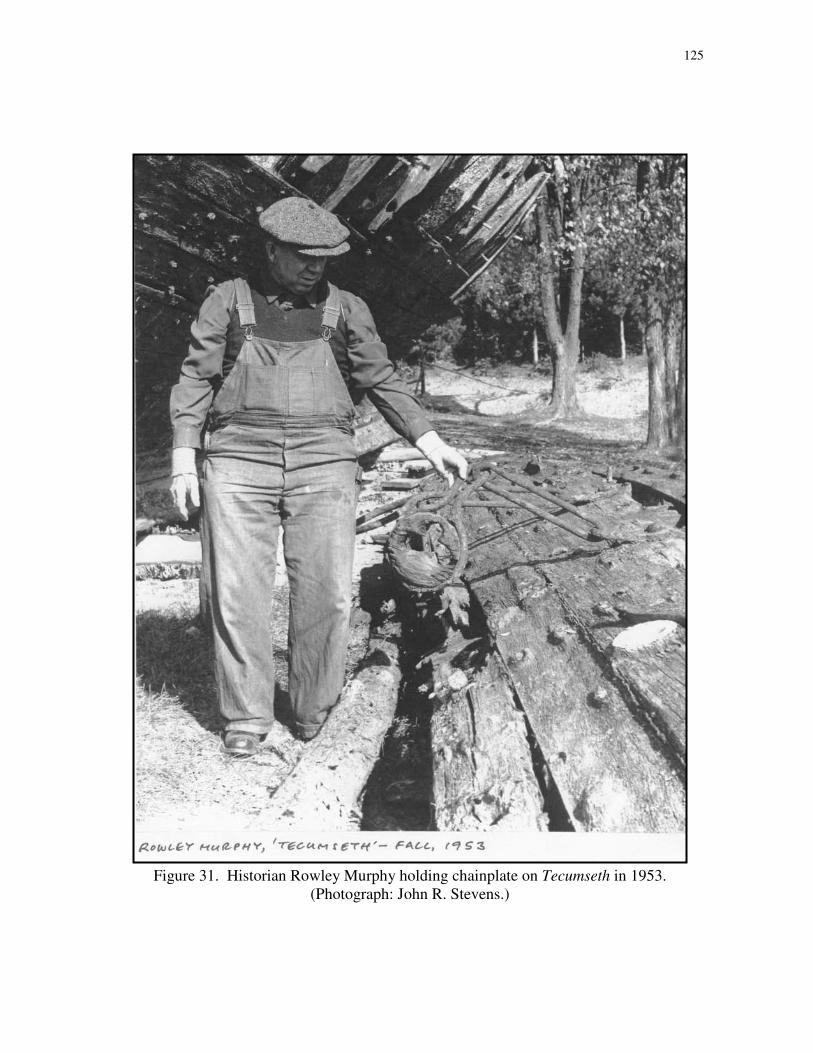
125
Figure 31. Historian Rowley Murphy holding chainplate on Tecumseth in 1953.
(Photograph: John R. Stevens.)
126
(26.68 cm) across, to accommodate an 8.00-inch (20.33 cm) deadeye. The smaller eyes
were 6.00 inches (15.24 cm) and 6.50 inches (16.51 cm) long.
The iron straps that held the deadeyes and the lowest figure-of-eight shaped links appear
to have been made to similar patterns. As each shroud was placed at a slightly different
angle, the chains themselves had to be made to different lengths. This appears to have
been accomplished by customizing the central oval link to the necessary size.
Planking the Ships
With the longitudinal and transverse timbers of the interior structure in place, the vessel
could be planked. The ash288
garboard strakes on either side of the keel were 12 inches
(30.49 cm) wide and 2 inches (5.08 cm) thick.289
These strakes may have warped and
shrunk since the vessel was built; the construction draft indicated that the outer planking
was originally 2.50 inches (6.35 cm) thick. While the garboard strake was made of ash,
oak and pine were also used for planking.290
Other planks were laid beside the garboard
and spiked to the interior frames with square-shanked spikes, 0.50 inches (1.27 cm) in
section.
The exterior planking was made as watertight as possible by driving pieces of cotton and
old rope, called oakum, in the gaps between the planks; the seams were then payed with
pitch. After caulking, the hull was painted. As a cost saving measure, Royal Navy
vessels were only to be caulked and painted once a year after the War of 1812.291
Unlike

127
seagoing vessels, which were subjected to wood-devouring organisms that live in
saltwater, the hulls of lake vessels did not need to be sheathed with copper.292
To allow water to run off of the decks, holes were cut into the exterior planking at deck
level. These holes, called scuppers, were lined with lead to prevent rot from developing.
The exterior planking was also used by sailors and those coming aboard. Short steps or
cleats were nailed to the sides. When a portion of topside planking was raised in 1953,
one such step and two lead-lined scuppers were evident.293
The interior planking, called ceiling planking, was laid over the inboard surfaces of the
frames. Historian Rowley Murphy noted in 1954 that the ceiling planking was made of
white pine.294
Besides contributing to the longitudinal stiffening of the hull, ceiling
planking protected the cargo from the water that inevitably leaked into the hull. Because
it played less of a role in keeping the vessel watertight, ceiling planking was not as thick
as the exterior planking, and was not caulked. The ceiling planking was whitewashed to
discourage rot.295
Several other artifacts were recovered during the 1953 salvage. These items reportedly
included “part of a cat-head, a corner of a hatch-coaming, ring bolts, shank painter, main
sheet traveller [sic] (probably)…round shot with broad arrow cast in them, a coin or
medal, and Royal Naval uniform buttons.”296
In addition, a glass deck prism or skylight
128
was recorded during Heinold’s investigations. Unfortunately, these artifacts could not
be located or inspected during the most recent research seasons.
Newash and Tecumseth and War of 1812-Era Ship Construction
Chronologically, Newash and Tecumseth are not War of 1812 vessels. The war was over
before their construction was ordered. Nevertheless, the conditions under which many
War of 1812 ship were constructed were still prevalent when Tecumseth and Newash
were built. Arguably, the greatest restraint that the War of 1812 placed on ship
construction came in terms of time. Ships were needed immediately, forcing
shipwrights to cut corners and eliminate time-intensive methods in order to deliver a
vessel quickly. Even though they were not traditional warships, Newash and Tecumseth
were wanted in short order. In spite of this, their actual construction time – from mid-
May to mid-August 1815 – while quick, does not indicate a situation of particular
duress.
The truncated construction time is manifested in the ways a shipwright utilized available
timber. Some hull features are best made with naturally curved timber. Such timber was
not always locally available and straight-grained timber was employed instead. Other
features are made by the careful measuring, cutting and shaping of large pieces of wood.
Seasoned timber, which was left to dry over time, is far superior to green timber, which
was recently cut. Green timber was left to dry after being put in place on a vessel,
potentially warping and twisting within the hull.

129
As previously mentioned, no knees were found in the hull remains of the two vessels.
This fact draws immediate comparison with the hull remains of the U.S. Navy Brig
Eagle, which was involved in the Battle of Plattsburgh Bay in September 1814. When
he built Eagle, shipwright Adam Brown recognized the amount of time that could be lost
in procuring proper timbers for knees. Brown chose instead to enlarge the clamp and
waterway, which performed a similar ship-stiffening function, and eliminated knees
from the hull entirely.
It should be remembered, however, that Eagle was a much larger vessel than Newash or
Tecumseth, with a length of 117 feet 3 inches (35.75 m) between perpendiculars and an
extreme breadth of 35 feet 5 inches (10.80 m).297
The longer hull was subjected to
greater stresses that could distort her shape or destroy it entirely. In addition, Eagle had
a much heavier deck load of 20 guns. The hulls of Newash and Tecumseth were
obviously not under the same strains as the larger ship. As smaller vessels, Tecumseth
and Newash may not have needed as much internal reinforcement.
The lack of knees within the hulls of Newash and Tecumseth may or may not be
indicative of the hurried construction time typical of some other War of 1812 warships.
After all, several lake warships of the period did have knees or some other form of
internal support that served the same function. One such method involved the
installation of long, straight-grained timbers that sat atop the ceiling planking within a
hull and ran from the keelson to the clamp. These riders were placed at a diagonal angle,

130
which helped distribute deck loads to several frames. Diagonal riders were found in
archaeological remains of the American War of 1812 brig Jefferson as well as in Royal
Navy shipwright Robert Seppings’ published writings on ship construction.298
Internal hull reinforcement was obviously of great concern to shipwrights. Those who
were tasked with building ships for only short-term purposes could afford to take some
shortcuts in construction. While it is not necessarily surprising that small, War of 1812-
era lake vessels like Newash and Tecumseth had no knees, it is surprising that little
regard for any other form of internal reinforcement was paid. No dimensions were taken
of the “wide shelf [clamp]” observed after the salvage, making it difficult to determine if
the hulls were reinforced with strong timbers in place of knees. John R. Stevens
recorded that “[t]he closest approximation to knees were heavy chocks placed under the
shelf at the ends of the…beams.”299
Unfortunately, Stevens did not record the
dimensions of these chocks. His drawing of the midship section of the vessel seems to
indicate that the clamp and heavy chocks were about the same size as the thickest strakes
of ceiling planking.
The lack of internal reinforcement could be indicative of a hurried construction time,
which may also be evident from some other features. Tecumseth’s gripe was made from
a large piece of straight-grained timber, and simply cut to the desired shape. The
stemson was made from unseasoned wood, which has since warped and distorted.
Tecumseth’s outer hull planking was fastened to the frames and end posts with a
131
combination of iron fasteners and treenails. Treenails are dowel-like rods of wood
inserted into a drilled hole. Often the ends were pegged or wedged to expand the wood
and ensure a tight fit. Treenails were driven through planking and frames, making a
secure joint. They were time-consuming to make and install, however. In a situation
where speed is vital and iron is available, iron fasteners may be employed to economize
the building time; for this reason, treenails were rarely used in wartime lake vessels.
When speed of delivery is critical, however, many other hull features may show signs of
hurried fabrication. Adam Brown increased the speed in which he could deliver Eagle
by only very roughly shaping many of the timbers. The keelson, for example, was not
notched to fit over the brig’s frames but was attached with iron drift bolts.300
The brig
was also built with very simple stem and stern assembly; the latter had no stern knee but
only a stack of horizontal timbers.
Tecumseth and Newash do not fit a particular pattern laid out by earlier warships. The
schooners had plain bow arrangements, made from a simple, functional design. This
utilitarian bow was typical of war-time vessels, unlike the elaborate bow seen on the
schooners Hamilton and Scourge, which sailed as merchant craft on Lake Ontario before
the war. The keelson on Tecumseth was notched to fit over each floor, a time-
consuming but ultimately advantageous method. Whereas warships built to withstand
heavy fighting were constructed from heavy, stout timbers, Tecumseth and Newash were
built with frames of modest dimensions on relatively widely-spaced centers. One feature

132
that seems to be common among most War of 1812-era ships is the use of green timber.
Even a few years earlier, the employment of green timber in construction may have
seemed foolish. The limitations of existing reserves of timber for shipbuilding were met
and exceeded during the war, and those vessels built immediately afterwards suffered
from the same lack of resources. Simple, quick construction seems to have influenced,
but not constrained Robert Moore’s design and creation of the two schooners.
Newash and Tecumseth had very shallow drafts, even for lake vessels. There was a
drastic difference between the depths of seagoing ships and lake vessels of the time.
With an abundance of freshwater and nearby shores, the hulls of lake vessels did not
need to be as large as seagoing ships. As was the case with internal hull reinforcement,
certain features were necessary on larger vessels but not on smaller ones. A smaller
vessel could, of course, be shallower, and smaller vessels often were. It should be noted,
though, that while Newash and Tecumseth were considerably smaller than other
contemporary British vessels on the lakes, they were the largest Royal Navy vessels on
Lakes Erie and Huron at the time. Enlarging the hulls by a few inches would have given
the ships greater carrying capacity. Even a few more inches of keel would have given
them more lateral resistance, and potentially better sailing characteristics.301
The
groundings of the two vessels on the bar at the mouth of Grand River should not indicate
that the hulls were too deep as they were designed but rather that the British
establishment was built at a poorly-chosen location.

133
By the time of their construction, both British and American shipwrights had been
building vessels in wilderness shipyards, under conditions of duress, for a few years.
The Owen brothers and their predecessors must have had some knowledge of the
constraints that local timber and quick construction placed on ship longevity. They must
have been aware that larger vessels, like the three frigates planned for Lake Erie, would
have been more vulnerable to the strains of heavy deck loads and long sailing careers
than smaller vessels constructed of the same timbers. Newash and Tecumseth may be
seen, then, as a compromise between the limits of local timber, time and maximum
capacity. The forests of the Great Lakes produced far more straight-grained timber than
compass timber. Perhaps E.W.C.R. Owen’s specification that the schooners be built to
130 tons was made with these resources in mind. Robert Moore then, having more first-
hand knowledge of the needs of the vessels, may have increased the vessels slightly – to
166 tons – on the thought that he could eke a bit more strength out of the available
resources.
134
CHAPTER XI
HULL ANALYSIS
A study of the hull302
was undertaken, based on the lines drawing made by Robert
Moore in April 1815 (see fig. 2). The draft shows three views of the ship: the body plan,
which shows several sections of the ship as if viewed longitudinally; the sheer plan,
which shows the ship as viewed from the side; and the half-breadth plan, which shows
half of the ship as viewed from above.
Based on the features shown in the drawing, it may be assumed that Moore’s draft was
made in preparation for construction. Moore’s drawing shows only sections, a single
waterline, and diagonals. Sections are shown in the body plan, which represent the
external faces of selected frames spaced every five feet (1.52 m); waterlines and
diagonals appear as curves in the half-breadth plan (diagonals are dashed lines). Aft of
midships, sections appear only for sections 4, 8, 12 and 14, at intervals of ten feet (3.05
m) though the profile and half-breadth plans show a section every five feet (1.52 m).
Details of the bow and stern are shown, illustrating the specific timbers needed to
assemble the stem, apron, keelson, deadwood and sternposts. These details would be
critical in constructing the spine of the ship. Section lines are necessary in creating the
frames that form the body of the hull and diagonals are useful in assuring that the
finished skeleton can be planked without problem. Other lines, which give a better idea
of the full hull form, may have been employed in the design phase, but omitted from the
construction drawing.
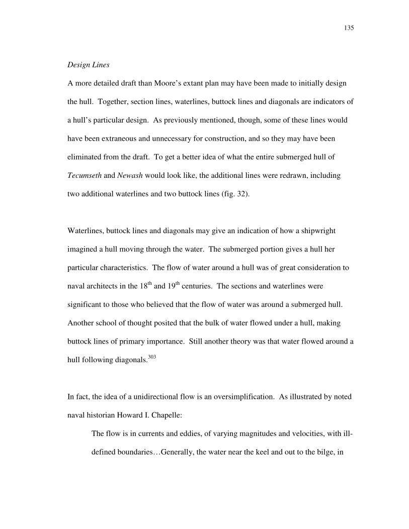
135
Design Lines
A more detailed draft than Moore’s extant plan may have been made to initially design
the hull. Together, section lines, waterlines, buttock lines and diagonals are indicators of
a hull’s particular design. As previously mentioned, though, some of these lines would
have been extraneous and unnecessary for construction, and so they may have been
eliminated from the draft. To get a better idea of what the entire submerged hull of
Tecumseth and Newash would look like, the additional lines were redrawn, including
two additional waterlines and two buttock lines (fig. 32).
Waterlines, buttock lines and diagonals may give an indication of how a shipwright
imagined a hull moving through the water. The submerged portion gives a hull her
particular characteristics. The flow of water around a hull was of great consideration to
naval architects in the 18th
and 19th
centuries. The sections and waterlines were
significant to those who believed that the flow of water was around a submerged hull.
Another school of thought posited that the bulk of water flowed under a hull, making
buttock lines of primary importance. Still another theory was that water flowed around a
hull following diagonals.303
In fact, the idea of a unidirectional flow is an oversimplification. As illustrated by noted
naval historian Howard I. Chapelle:
The flow is in currents and eddies, of varying magnitudes and velocities, with ill-
defined boundaries…Generally, the water near the keel and out to the bilge, in

136
Fig
ure
32
: R
evis
ed l
ines
dra
win
g, sh
ow
ing
tw
o a
dd
itio
nal
wat
erli
nes
an
d t
wo
ad
dit
ion
al b
utt
ock
lin
es.

137
the forebody, appears to move under the hull, while that at the bilges follows a
fairly normal diagonal, and that above the bilge moves around the sides of the
hull.304
However water was believed to flow around the hull, it presented resistance to motion.
Resistance occurs in two ways: “frictional resistance due to the sliding of particles of
water over the immersed surface,” and “wave resistance due to the formation of waves
by the boat.”305
Reduction of this resistance was of primary importance in designing a
swift hull. It is not expressly clear that Robert Moore set out to design a particularly fast
ship. In the nature of their duties, though, it would be advantageous to have swift sailing
characteristics, and it is known that Tecumseth and Newash were intended to be “sharp”
vessels.
Designing a sharp vessel involves minimizing any unnecessary bulk in the hull and
reducing resistance. Earlier vessels, built to maximize cargo capacity, had nearly
vertical stems and sternposts and flat-bottomed sections. Sharp vessels, in contrast, had
angular, V-shaped sections and angled, or raked, stems and sternposts. Raking the stem
forward and the sternpost aft gave the vessel a longer overall length without a longer
keel.
Raked stems and sternposts allowed both Newash and Tecumseth a length over the deck
of 70 feet 6 inches (21.49 m). This number is slightly misleading, though, because the
138
portion of the hull actually in contact with the water was much less. Obviously, lower
portions of the hull are shorter in length. As the amount of hull immersed could vary at
any time due to loading considerations and dynamic conditions of heeling, it is very
difficult to analyze a hull except in theory. For the purposes of this discussion, the
predicted load waterline that appears on Robert Moore’s draft was used as the upper
extreme of the submerged hull. Tecumseth and Newash had a length along the load
waterline, as predicted by Moore’s draft, of 66 feet 6 inches (20.27 m).
In his study of fast sailing hulls, The Search for Speed Under Sail: 1750 - 1855, Howard
I. Chapelle noted three main areas where speed advantages could be had. “[A] sharp
entrance was advantageous for speed as was length of hull, and also that hollow in the
vicinity of the forefoot…could be expected to produce a fast sailing vessel.”306
While
true understanding of hydrodynamics would not come until much later, empirical
observations and experimentation led to some early conclusions about fast hull forms.
Many of the characteristics had been discovered as early as 1670, and documented in the
Pepysian Library.307
The entrance of a vessel, or the forward surface she presents to water, is of primary
importance in speed. As a ship moves forward, she first encounters still water in front of
her as resistance. That water must be pushed aside for the vessel to move. A plane
placed perpendicularly to a surface of water will present the most resistance to forward
motion. As that plane is angled away from the perpendicular, resistance is reduced.

139
Essentially, this is the same as sticking a hand out a moving car’s window. The most
pressure is felt when the hand is perpendicular to the road, with less and less pressure as
the hand is angled in either direction. Resistance decreases in approximate proportion to
the sine of a plane’s angle to the water. A plane perpendicular to a water surface will
present a resistance factor of 1. A plane at 80º to the same water surface has a resistance
factor of .98. A plane at 70º presents a factor of .94, and so on.308
Newash and
Tecumseth’s stems had an angle of 62º to their load waterlines (fig. 33). Though the
resistance factor at that angle, .88, is only a theoretical expression, it is apparent that
reducing the hull’s resistance at the entrance was a concern of the designer. The
entrance of the submerged body is also significant, just like the entrance of the stem.
The angles of the two additional buttock lines were 34° and 28°, indicating the sharpness
of the hull form.
Figure 33: Angle of entrance in bow.
140
After the sharp entrance, the hull gradually widens. This wider portion of the hull
actually encounters less resistance than the entrance. The stem is always encountering
water that is not moving, while the after parts of the ship encounter water that is already
in motion in the same direction as the ship, making it less resistant than still water.309
Logically, then, the widest point in a ship should occur in the middle of her length, so
that the hull forms a nice oval shape for water to flow around. Naval architects in the
16th
century noticed, however, that fish are not found with that nice, ovular shape; a
painting by Matthew Baker shows a fish form superimposed on the submerged portion
of a ship’s hull. The widest part of a fish is found further towards its head than the
middle of its body length. When this characteristic was adopted in ship design, it was
called a “codfish head.” A codfish head-type hull has the widest point, or midships
section, well forward of the midpoint of the waterline length. On Tecumseth and
Newash, the midships section is located 6 feet 7 inches (2.01 m) forward of the midpoint
of the load waterline (fig. 34).
One worry of a codfish head-style hull is the potential for wave-making, the second part
of resistance. As a vessel travels through the water, she creates her own waves. It is
easy to imagine the wake of a modern power vessel, but even sailing ships create waves
as they travel. These waves present additional resistance from the water. Form and
proportion almost exclusively govern a hull’s wave-making resistance.310
A codfish
head bow can present problems in wave-making resistance. With the midships section
forward in the ship, it has the potential to create waves early in the ship’s movement,

141
Fig
ure
34
: D
ista
nce
bet
wee
n m
idsh
ips
sect
ion
an
d c
ente
r o
f lo
ad w
ater
lin
e.
142
reducing her speed. One way to reduce this potential is to have a “raking midsection;”311
the widest point of the vessel is moved further aft in the lower portions of the ship.
Tecumseth and Newash have only a slight rake to their midsections. The widest point in
the load waterline is at the midships section, but in the lower two waterlines, it does
appear very slightly further aft.
Length of a vessel, along the load waterline, is also significant to speed. Physically, a
hull is limited in terms of achievable speed by wave-making resistance. This limitation,
called hull speed, comes when a vessel is restricted by the waves she makes. A vessel
traveling through the water creates a bow wave and a stern wave. At the upper limits of
her potential speeds, the bow and stern of the ship are at the same point in the bow and
stern waves, and a long trough forms between them. At this point, the hull is essentially
trapped in a hole. Sailing at speeds higher than hull-speed is difficult, but not
impossible. The longer a hull is, however, the longer the time before hull-speed is
achieved. Simply put, the longer a ship is, the faster she can go.
In addition to the codfish head, the draft of Newash and Tecumseth shows a hollow, or
concavity, in the load waterline seen in the half-breadth plan. Such a hollow has a
tendency to create a “shoulder” abaft the hollow, which produced greater wave-making
resistance. Variables such as vessel speed or hardness of shoulder affected the impact of
these shoulders in wave-making resistance. To lessen their impact, shoulders were
raked. This meant shaping the hull so that “the shoulders in each level line (or
143
waterline), from load line down, were shifted aft in the forebody and forward in the
afterbody.”312
With the two additional waterlines, it can be seen that the hollow indeed shifts aft further
down the hull. The rake in the hollow is far more pronounced than the rake in the
midsection. It is interesting to note that there does not appear to be any hollow near the
sternpost, as might be expected. Chapelle’s study had noted that hollow in the after
portions of the ship could also be expected to give a ship swift sailing qualities. In the
case of Tecumseth and Newash, such hollow might have been a little too extreme, given
the ships’ shallow drafts.
The draft of a ship is usually significant in determining her characteristics, particularly in
the cases of Newash and Tecumseth . Interestingly, depth is not as great a concern in
hull design as one might think. “Resistance is nearly constant for all depths at any
named speed. In other words, depth of immersion does not seem to change
resistance.”313
This allowed ocean-going ships, which did not face the draft constraints
that ships in shallower waters did, to balance a lofty rig with a deep hull. In shallow
waters, however, deep hulls were impractical. Arguably the most striking feature of
Newash and Tecumseth were their remarkably shallow hulls. In the draft, the ships were
predicted to draw 6 feet (1.83 m) forward and 9 feet (2.74 m) aft.

144
When the keel is removed as a factor in examining the hull, the ships draw even less.
The mean draft, averaged from the depths in the bow and stern, is only 6.25 feet, or 6
feet 3 inches (1.91 m). The shallowness of the hulls must be kept in mind when
examining the next calculations. It is one thing to have a sharp-hulled vessel, but
another thing to have a sharp hull that is exceptionally shallow.
It may seem difficult to compare vessels of different sizes, or even the same sizes. Two
vessels built with the same overall length may appear very different below the water
line. To compare ships, it is helpful to look at a number of different ratios.
Coefficients and Ratios
Most hull coefficients and ratios involve the same basic hull dimensions, which are
given in Table 2. Many of the calculations do not take the keel, stem and sternpost into
account, as they are measures of the hull alone.
Table 2: Hull Dimensions
Length over deck 70 feet 6 inches (21.49 m)
Maximum Beam 24 feet 5 inches (7.44 m)
Load Waterline, extreme 66 feet 6 inches (20.27 m)
Load Waterline without posts 63 feet 11 inches (19.49 m)
Load Beam, moulded 23 feet 4 inches (7.11 m)
Load Beam, extreme 23 feet 10 inches (7.27 m)
Mean Draft 6 feet 3 inches (1.91 m)
Volume of Hull, excluding keel and posts 3989.10 cubic feet (113.05 m3)
Volume of Hull, inclusive of posts 4068.97 cubic feet (115.31 m3)
Volume of Hull, long tons in salt water314
116.26 long tons
Volume of Hull, long tons in fresh water 119.05 long tons
Waterplane Area 1118.67 square feet (103.97 m2)

145
Two ratios that are easily calculated are the length-to-beam ratios. Length-to-beam
ratios can be calculated from overall maximum dimensions, or from load waterline
dimensions. Using the overall dimensions of length over the deck and maximum beam,
a ratio of 2.88:1 is found. Using dimensions of load waterline length and beam yields a
ratio of 2.70:1. These ratios show that the vessels were more than twice, but not quite
three times, as long as they were wide. Typically, ratios between 2.5:1 and 3:1 are
indicative of good sailing ships. Later ships would have even higher length-to-beam
ratios, but the ratio is not necessarily indicative of any quality on its own.
Like the length-to-beam ratio, there are several hull coefficients that can be calculated,
but which are fairly arbitrary on their own. The coefficients are useful in comparing
dissimilar and similar ships. In his work The Search for Speed Under Sail: 1750 – 1855,
Chapelle calculated hull coefficients for 100 vessels from the period mentioned. For
comparison purposes, coefficients for the vessels from 20 years previous to Newash and
Tecumseth’s construction to 20 years later are provided in Appendix D.
A block coefficient is a ratio of the volume of a ship’s submerged hull (exclusive of keel,
stem and sternpost) to the volume of a block of the same overall dimensions (load
waterline x load beam x mean draft). For Tecumseth and Newash, this is the ratio of
3989.10 cubic feet (113.05 m3) to 9905.73 cubic feet (280.73 m
3), or .40.
146
A midship coefficient is a ratio of the area of the midship section to a plane of the same
overall dimensions. The area of the midship section for the two hulls is 95.22 square
feet (8.85 m2). The area of a plane of the same overall dimensions (load beam x depth at
midship section) is 141.02 square feet (13.11 m2), yielding a ratio of .68.
The area of the midship section also factors into the prismatic coefficient. This is a ratio
of the volume of the submerged hull to a prism having the same area as the midship
section and the length of the load waterline. The ratio of 3989.10 cubic feet (113.05 m3)
to 6086.18 cubic feet (172.47 m3) is .66.
Another ratio that can be useful in comparing hulls is the camber-length ratio. The
information for this ratio is derived from a quarter-beam buttock line. As previously
discussed, the buttocks are lines which describe the shape of the hull as if sliced
longitudinally and viewed from the side. For this ratio, a buttock line is drawn at “one
quarter of the load waterline beam (out from the longitudinal and vertical centerlines of
the hull)”315
(see fig. 32). Using only the portion of that line which is below the load
waterline, the length and maximum depth, or camber, are measured. The ratio of the
camber to the length provides further insight into two hulls having the same prismatic
coefficient. “If two vessels have the same or nearly the same prismatic, the one with the
larger quarterbeam buttock camber-length ratio can usually be presumed to be the
faster.”316
A buttock line placed 5 feet 10 inches (1.78 m) from the centerline is 52 feet
147
10 inches (16.11 m) long with a 4 feet 6 inch (1.37 m) camber. This yields a buttock
camber-length ratio of 11.74.
Buttock lines can also be used to examine how the forward part of the hull would have
encountered the water. After all, a sharp stem is wasted if the rest of the hull is not built
upon similar principles. The angle formed by the intersection of a buttock line placed 2
feet 11 inches (0.89 m) from the centerline is 34º. The angle at the quarterbeam buttock
is 28º.
Chapelle calculates a displacement-length ratio for his list of hulls as well. This ratio is
calculated by the following formula.
DL = Displacement (0.010 x Length)3
Since this number is most useful in a comparison with the coefficients from Chapelle’s
work and those vessels were ocean-going hulls, the saltwater displacement for
Tecumseth and Newash was used. A saltwater displacement of 116.26 long tons and a
length of 63 feet 11 inches (19.49 m) yields a displacement-length ratio of 445.23.
A final ratio used to compare vessels, particularly those with noted speed qualities, is a
speed-length ratio. Swift vessels can be built to any size or length, but those with longer
load waterlines are faster, at least theoretically.317
Nevertheless, a smaller vessel might
achieve great speed for her length, placing her on par with a much larger vessel even

148
though the larger vessel may have a higher overall speed. To compare these two vessels,
a speed-length ratio is used. Calculating this is simply a factor of dividing a known
speed of the vessel by the square root of her load waterline length to arrive at a factor.
Chapelle gave the following illustration of this concept:
For example, an extreme case may be used to show the use of this quotient: a
vessel 121 feet [36.89 m] on the load waterline has recorded a run of 16 knots,
while another vessel 240 feet [73.17 m] on the load waterline ran 21 knots.
Which of the two vessels had the faster design on the basis of speed-length?
Calculating the speed-length ratio of each it is found that the 121-foot [36.89 m]
vessel has a ratio of 1.455 while the ratio of the 240-foot [73.17 m] vessel is
1.355. This indicates that the 121-foot [36.89 m] vessel is of the basically faster
design.318
None of the surviving logbooks of Newash or Tecumseth record any known speeds.
Speed-length ratios may still be calculated, however, on the basis of known examples
from fast ships. Chapelle noted that speed-length ratios of 1.25 – 1.35 were not
uncommon in seagoing sailing ships. With a load waterline of 66 feet 6 inches (20.27
m), a speed of 10.19 knots would have to be achieved to reach a speed-length ratio of
1.25. For a ratio of 1.35, 11.01 knots would have to be reached.
It is important to note, as Chapelle did, that the observed maximum speed “is the highest
speed recorded in one hour of sailing on any point.”319
Over the course of a passage,
149
particularly one of long duration, the average speed fell significantly, and a speed-length
ratio calculated for an average speed would be much less than those just discussed.
Unfortunately, there are no decisive boundaries in terms of these ratios. There is no
definition of a sharp vessel, even in terms of these various coefficients. These terms are
used only for comparison of different hulls. Of course, it must also be considered that
all calculations here were done from a construction drawing, which may or may not have
truly reflected the completed vessels.
Waterplane Area and Immersion
A waterplane coefficient can be calculated by comparing the known waterplane area
with a plane having the dimensions of the extreme load beam and the load waterline
length. The waterplane area was calculated at 1118.67 square feet (103.97 m2), while
the larger plane had an area of 1584.89 square feet (147.29 m2), giving a coefficient of
.71.
The waterplane area is also used in another calculation which has a little more practical,
albeit theoretical, value. The waterplane area, when divided by a factor of 420, gives the
number of tons necessary for one inch of hull immersion.320
This number, called TPI
(for Tons Per Inch), is 2.66 long tons for Tecumseth and Newash. This means that, at
this particular draft, 5958.4 pounds (2708.36 kg) loaded onto the vessels would cause
their drafts to increase by one inch.

150
To put this number into perspective, let us look at the example of lightening the hulls to
cross the Grand River bar at the end of the winter of 1815 – 1816. Second Master
Childs’ logbook records a draft of 7 feet 2 inches aft (2.18 m). The prescribed draft from
Moore’s draft was 9 feet (2.74 m) aft. In order to achieve this difference of 22 inches
(55.89 cm), it may be estimated that at least 50 tons321
(112,000 pounds or 50909.10 kg)
had to be removed from the hull.
The TPI can also be used to look at the effect of the guns on deck. Using the average
weight of two 24-pounder carronades and two 24-pounder long guns, it was determined
that the guns alone added 14,560 pounds (6618.18 kg) to the hull. The guns alone were
responsible for approximately 2 inches (5.08 cm)322
of the vessels’ drafts.
Deck-Edge Immersion and Downflooding
One final calculation that can be found from analyzing the construction draft is the angle
of deck-edge immersion. This angle may be of little use in examining a hull on paper,
but it was of incredible importance to those sailing in the ship. The angle of deck-edge
immersion is the limit of how far a ship can be heeled without running the risk of
downflooding.
Forces of both gravity and buoyancy are always at work in a hull afloat:
Water exerts an upward pressure on the underwater surfaces of the vessel that
tends to push it up and out of the water. The upward forces of buoyancy are
151
opposed by the downward forces of gravity which tend to make the vessel sink.
The buoyant forces, which act vertically upward, are exactly equal to the weight
of the water which the vessel displaces.323
A static equilibrium between these forces keeps a vessel upright when still, and the
tendency towards equilibrium returns a vessel to her upright position when temporarily
heeled. Every hull tends toward a static position, and the tendency to do so is called a
righting arm. The righting arm is greatest when the vessel is heeled to approximately the
same angle as the deck-edge.324
Beyond the angle of deck-edge immersion, the righting
arm still exists, so a vessel can return to an upright state after heeling beyond deck-edge
immersion. At greater angles, the righting arm decreases, and the stability of a ship may
be compromised further by downflooding or loose water on the deck. The angle of
deck-edge immersion may be considered the limit of comfortable sailing, but not a point
of no return.
In a vessel such as Newash and Tecumseth, with their low open rails, deck-edge
immersion is exceptionally low. The angle of deck-edge immersion from Robert
Moore’s draft was taken as the angle between the midships load waterline and the height
of the deck at the midships section. (fig. 35). It is a frightening 18º.325
There is a slight
difference between the height of the deck and the maximum height of the outer planking
at the same section. The planking extends 1 foot 2 inches (0.36 m) higher than the deck.
This gives a slight buffer, allowing the ship to heel to 21º before water actually began

152
washing onto the deck. In comparison, Chapelle noted a range of heeling angles for
many War of 1812-era ships of 45º to 50º, with other ships reaching ranges of 55º to
60º.326
Tender and Stiff Vessels
The state of equilibrium between forces of buoyancy and gravity, as mentioned, keeps a
vessel upright. The stability of a ship is concerned with the vessel’s ability to right
herself after a roll. How a vessel is loaded affects the way a vessel rolls and rights
herself, and how long she may take.
Figure 35: Angle of deck-edge immersion.
(Detail from John R. Stevens, “The Story of
H.M. Armed Schooner Tecumseth, 28.)
153
If a vessel is laden in such a manner as to be top-heavy, she will be considered “tender.”
This means that the vessel has a weak ability to right herself, and will have a long,
sluggish roll. If an opposing measure is taken, and a vessel is loaded with too much
weight concentrated low in the hull, she will become “stiff.” A stiff vessel has a strong
tendency to return to an upright position, but may do so with quick, harsh motions that
can damage the vessel.
Both tender and stiff conditions can become problematic. A stiff vessel may be
uncomfortable for those onboard, “and can also lead to synchronous rolling where the
period of the ocean waves and the apparent rolling period of the vessel are exactly the
same – resulting in very heavy rolling or, if sustained, capsizing.”327
A tender vessel has
poor stability and a smaller margin of safety if flooding occurs or her cargo or ballast
shifts. Tenderness can also cause a vessel to “capsize without warning as a result of a
series of unexpectedly high waves, heavy weather or relatively slight damage…There
will also be a greater tendency for seas to break over her weather decks.”328
Discussion: Hull Design and Purpose
In the end, hull analysis is difficult. It should be remembered that all of these
coefficients and ratios and numbers have been calculated from a paper drawing. The
draft may not truly represent the ships as they were launched. Furthermore, after the
numbers are calculated, they must be examined.
154
Think of the hundreds of models of cars on the road today. There are miniscule sub-
compact cars, monstrous trucks and everything in between. Ships are no different. Even
today, there are dinghies, daysailers, cruise ships and freighters. Finding any sort of
pattern among the multitudes of vehicles is difficult, even painful. Perhaps the pattern is
not in the cars but in the people who drive them. After all, the owner of the sub-compact
expects a certain level of performance and selected that vehicle for specific reasons, just
as the owner of the enormous truck chose it.
Hulls, too, were built for specific functions. Newash and Tecumseth were built to
transport goods. They also had to carry guns and a large crew who were to be instantly
ready for action. They were built as sharp vessels, with fine entrances, hollows in the
bow and three feet (0.91 m) drag to their keels. These were probably incorporated into
the design to make the ships swift. The distant parts of the Canadian frontier needed
vessels that could move supplies and men quickly. Yet, the coefficients do not reveal
that the hulls were built to any extremes. They were by no means the sharpest vessels of
their day, nor is there evidence that they were lauded for exceptional speed.
It should be noted and stressed, however, that these hulls were extremely shallow, a
condition which is not adequately reflected in the hull coefficients. Work on the lakes
necessitated a shallow draft, and the Great Lakes offered more protection than would be
seen in the middle of the ocean. Still, the lakes were not subjected to continuous calm
155
conditions, and there must have been times when Tecumseth and Newash became truly
frightening ships.
In addition to the shallowness of the hulls, stability was a concern, and the dynamic
nature of their work did little to alleviate this. Each time that Newash and Tecumseth
were loaded, a new stability condition was created within their hulls. As transport
vessels, the officers and crew would have had opportunities to observe their vessels in
various states and conditions, thus gathering a feeling for how proper loading could be
accomplished. The fact that their cargoes regularly included men, women and children,
who could not be counted on to remain in one place, must have been a particular
difficulty in ensuring the safety of the ship and those aboard.
It is almost a shame that the careers of these vessels were so affected by the political
atmosphere of the time. It would be very interesting, to say the least, to see how these
ships might have been regarded by their officers and crew had the vessels had longer
lives.
Penetanguishene’s Sailing Replica
Sailing replicas and reconstructions can often be useful in experimental archaeology,
offering a different perspective of a sailing vessel than what can be gathered from
historical documents and hull remains. Replicas and reconstructions can also be
beneficial in raising awareness of an area’s maritime past by providing an active,
156
tangible exhibit for the public to experience. In order to carry members of the public,
however, modern vessels must comply with a rigid set of safety standards. Often, these
standards involve compromising some of the historical integrity of a vessel, in order to
fulfill a certain mission.
In 1991, a sailing replica of H.M. Schooner Tecumseth was built for Discovery Harbour
(Havre de la Découverte). To meet with modern safety standards, some concessions
were made in the design and construction of the schooner. The most notable of these
was the choice of hull material; H.M.S. Tecumseth, as she is known, is a steel-hulled
vessel. Undoubtedly, steel was chosen as the building material because of the increased
longevity and ease of maintenance, as compared to a wooden hull. Wooden vessels
require continual inspection and upkeep, which can become very costly.
The choice of steel as a hull material has limited the number of comparisons that can be
drawn between the replica vessel and the original hull design and remains. Steel
construction methods are completely different than wooden shipbuilding, and steel
vessels display a distinct set of characteristics on the water. In the summers of 2007 and
2008, H.M.S. Tecumseth was on display at the museum’s waterfront, though in previous
years she had sailed to other Great Lakes ports. Because recent sailing schedules had
not allowed many of the museum staff to gain first-hand experience on the schooner, it
was difficult to gather anecdotal information on the vessel’s sailing characteristics. To
avoid any confusion and focus the current discussion to the information that can be

157
gathered from the documentary and archaeological remains of Tecumseth and Newash,
this discussion will not include references to the sailing replica.

158
CHAPTER XII
RECONSTRUCTING THE SCHOONER RIG
A number of historical documents are stored in the Bayfield Room at the
Penetanguishene Public Library in Penetanguishene, Ontario, and are accessible for
viewing upon request. These documents focus on Penetanguishene’s naval and military
history, as well as the town’s early development. A number of documents from the War
of 1812 and early 19th
century can be found as well, having been copied from archival
materials now held at the Library and Archives of Canada. One particular item, a
rigging warrant written by Lieutenant Thomas Bushby in 1815, contained a wealth of
information on Newash’s sailing rig. A majority of the documents were compiled and
consulted during the research that allowed the reconstruction of the Penetanguishene
Navy Yard, now open to the public as Discovery Harbour (Havre de la Découverte).
Some material dealt specifically with research conducted in preparation for the
construction of Discovery Harbour’s replica sailing vessel, H.M.S. Tecumseth. Previous
to the construction of this vessel, John R. Stevens published a rigging plan based on
research and hull elements observed in 1954 (fig. 36). Stevens portrayed Tecumseth in
her early sailing configuration, with square main and fore topsails, while the modern
replica sails with a gaff topsail on the mainmast.
In favor of a fresh approach, these previous rigging interpretations were disregarded in
the preparation of the current reconstruction (fig. 37). The major sources for this
reconstruction were the masting and rigging treatises of David R. Steel, originally

159
Fig
ure
36
: Jo
hn
R. S
tev
ens’
rec
on
stru
cted
rig
gin
g p
lan
. (
Det
ail
fro
m J
oh
n R
. S
tev
ens,
“T
he
Sto
ry o
f
H.M
. A
rmed
Sch
oo
ner
Tec
um
seth
,” 2
9.)

160
Fig
ure
37
: R
eco
nst
ruct
ed s
cho
on
er r
igg
ing
pla
n.

161
published in 1794329
and John Fincham, originally published in 1829.330
. Specifications
for many elements were taken from Darcy Lever’s The Young Sea Officer’s Sheet
Anchor, originally published in 1819. The reconstruction was also heavily informed by
Thomas Bushby’s rigging warrant,331
taken aboard Newash in September 1815. It
should be noted that this warrant lists the sails onboard in the schooner’s first
configuration, including a square-rigged main topsail and topgallant. The warrant omits
the gear for those sails, however, and includes the running rigging and blocks needed for
a gaff topsail to be rigged on the main topmast.
Bushby’s rigging warrant contains the sizes and lengths of the standing and running
rigging, and the number and sizes of the associated blocks. From this, it is known that
the schooners carried nine sails in their original configuration: flying jib, standing jib,
gaff foresail, square sail (foresail), fore topsail, fore topgallant, boom mainsail, main
topsail, and main topgallant.
To support these sails, the fore and main masts were each made of a two-part assembly,
the lower mast and topmast. The topgallant pole extended from the topmast, but was not
a separate piece. In front of the ship, a similar two-part assembly of bowsprit and
jibboom made up the basis of the headrig. Chapter III has already discussed how stays,
runners, backstays, and shrouds form a network of rigging to support these spars,
distribute any strain or load on them, and keep them in place. Shortly after launching in
1815, Newash’s spars were raised in the following order: main lower mast, fore lower
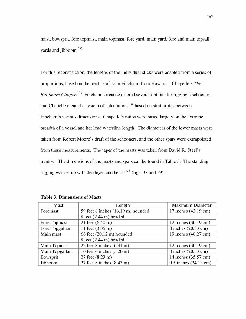
162
mast, bowsprit, fore topmast, main topmast, fore yard, main yard, fore and main topsail
yards and jibboom.332
For this reconstruction, the lengths of the individual sticks were adapted from a series of
proportions, based on the treatise of John Fincham, from Howard I. Chapelle’s The
Baltimore Clipper.333
Fincham’s treatise offered several options for rigging a schooner,
and Chapelle created a system of calculations334
based on similarities between
Fincham’s various dimensions. Chapelle’s ratios were based largely on the extreme
breadth of a vessel and her load waterline length. The diameters of the lower masts were
taken from Robert Moore’s draft of the schooners, and the other spars were extrapolated
from these measurements. The taper of the masts was taken from David R. Steel’s
treatise. The dimensions of the masts and spars can be found in Table 3. The standing
rigging was set up with deadeyes and hearts335
(figs. 38 and 39).
Table 3: Dimensions of Masts
Mast Length Maximum Diameter
Foremast 59 feet 8 inches (18.19 m) hounded 17 inches (43.19 cm)
8 feet (2.44 m) headed
Fore Topmast 21 feet (6.40 m) 12 inches (30.49 cm)
Fore Topgallant 11 feet (3.35 m) 8 inches (20.33 cm)
Main mast 66 feet (20.12 m) hounded 19 inches (48.27 cm)
8 feet (2.44 m) headed
Main Topmast 22 feet 8 inches (6.91 m) 12 inches (30.49 cm)
Main Topgallant 10 feet 6 inches (3.20 m) 8 inches (20.33 cm)
Bowsprit 27 feet (8.23 m) 14 inches (35.57 cm)
Jibboom 27 feet 8 inches (8.43 m) 9.5 inches (24.13 cm)

163
Figure 38: Larboard deadeye.
(Detail from Darcy Lever, The
Young Sea Officer’s Sheet Anchor,
14, 22, 24, figs. 113, 167, 176.)
Figure 39: Rigging
heart. (Detail from
Darcy Lever, The
Young Sea
Officer’s Sheet
Anchor, 14,
fig. 114.)
164
Main Rigging
The main lower mast itself was raised with the aid of sheers, and placed into the main
mast step. The lowest part of the mast is called the heel. In the case of Newash and
Tecumseth, the heels of the masts were roughly shaped to fit into the mortise in the mast
steps. Moving upwards from the heel of the mast, the mast passed through a hole in the
deck, where it was supported and secured by mast partners and wedges.
The schooner rig presented an interesting challenge in interpreting the main rigging. On
a fully square-rigged vessel, the main stay led directly to the deck without interfering
with any other sails. Such a stay would have interfered with the proper operation of the
fore-and-aft rigged foresail. A stay leading between the heads of the main and fore
lower masts would not have the proper downward angle, and would have to be carefully
placed to avoid interfering with the operation of the main topsail.
The rigging arrangement proposed here combines these two types of stays. Newash’s
rigging warrant lists a “Main Mast Head Stay”336
and two “Main Mast Deck Stays,” of
different size rope. From this, it may be assumed that two stays were rigged from the
main lower mast hounds to the deck, one on either side of the ship. The ideal
arrangement would have these stays leading as far forward as possible within the
confines of the hull. Two 9-inch (22.87 cm)337
double sheave blocks were rigged to each
of the pendants of the deck stays, which allowed the stays to be hove taut or slacked
off.338
These blocks were set up as a two-fold purchase; (fig. 40) four times the

165
advantage was gained. When sailing, the leeward deck stay was slackened and moved
or nipped out of the way, to avoid cutting into the shape of the foresail. The weather
deck stay remained taut, supporting the mast. During tacking or wearing operations, or
in cases when both stays were slack, the mast was supported by the mast head stay,
which ran between the main and fore lower masts.
The main runners, or breast backstays, opposed the main stays, and were given as much
of an aft lead as possible, while remaining within the confines of the hull. These were
made of two pieces: a pendant, which led down from the lower mast hounds, and a
block and tackle system, which allowed the runner to be tensioned. The end of the
pendant was seized around a 9-inch (22.87 cm) single sheave block. A runner line was
rove through the sheave of this block, and a 9-inch (22.87 cm) double sheave block was
Figure 40: A
two-fold
purchase.
166
seized into the end.339
A single luff purchase was set up with the double sheave and
another 9-inch (22.87 cm) single sheave block (see fig. 11). The luff tackle provided
triple the power than without purchase.
Moore’s drawing of the ships indicates that the mainmast carried three shrouds on each
side of the ship.340
The forward two legs on each side were made from the same line,
which was middled and seized to form an eye. The after legs were made as single legs,
having an eye spliced into the end. Each shroud had a deadeye made into its lower end,
which was connected, by a lanyard, to another deadeye attached to the hull of the ship.
The shrouds were tensioned with purchase blocks and secured with a lanyard. Each
lanyard had a stopper knot, usually a lanyard knot or Matthew Walker knot (fig. 41) tied
in one end, and was rove through the holes of the deadeye.341
A series of smaller lines
tied between each shroud leg provided ratlines for sailors to climb on when working
aloft.
Fore Rigging
Rigging the fore lower mast presented less of a challenge than the main, but was not
straightforward. Bushby’s rigging warrant does not list a fore stay at all. There must
have been one, however, for the vessel to sail. James Childs’ logbook contains an entry
on setting up a “preventer fore stay,”342
indicating that the original fore stay was
insufficient, but not that it was absent completely.
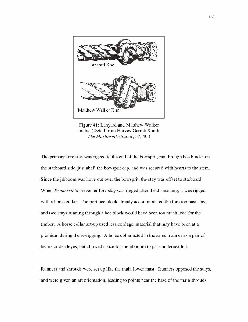
167
The primary fore stay was rigged to the end of the bowsprit, ran through bee blocks on
the starboard side, just abaft the bowsprit cap, and was secured with hearts to the stem.
Since the jibboom was hove out over the bowsprit, the stay was offset to starboard.
When Tecumseth’s preventer fore stay was rigged after the dismasting, it was rigged
with a horse collar. The port bee block already accommodated the fore topmast stay,
and two stays running through a bee block would have been too much load for the
timber. A horse collar set-up used less cordage, material that may have been at a
premium during the re-rigging. A horse collar acted in the same manner as a pair of
hearts or deadeyes, but allowed space for the jibboom to pass underneath it.
Runners and shrouds were set up like the main lower mast. Runners opposed the stays,
and were given an aft orientation, leading to points near the base of the main shrouds.
Figure 41: Lanyard and Matthew Walker
knots. (Detail from Hervey Garrett Smith,
The Marlinspike Sailor, 37, 40.)

168
The fore runners were set up with a runner line and luff tackle. Three pairs of shrouds,
as evident from Moore’s draft, steadied the fore lower mast laterally.
Bowsprit Rigging
The bowsprit itself can be imagined as a mast that has been leaned forward. Like the
main and fore masts, it had stays and shrouds. In this case, the stays were called
bobstays, and led to the ship’s stem. Unlike the main and fore lower mast stays, which
had hearts seized into their lower ends for obvious reasons, bobstays had hearts or
deadeyes seized into their upper ends. This prevented the vulnerable lanyard from
excess rot caused by immersion in water, and gave the bobstay hearts a clearer lead back
onto the deck when they were tensioned.
The rigging warrant lists only one length of cordage for a bobstay, but James Childs’
logbook records the plural “bobstays” on several occasions, even before the
dismasting.343
It is probable, then, that two bobstays were set up. Since the bobstays
supported the bowsprit by pulling it downward, the lowest lead possible was preferred.
Because of the low angle of the bowsprit, this meant placing the bobstay bridles near the
waterline. Shortly after she was rerigged, Tecumseth’s crew shifted her bobstays “a foot
[0.30 m] further down.”344
This may have meant that the bobstays were submerged –
perhaps continually or only periodically.
169
The hemp standing rigging required some form of covering to keep water and sunlight
from destroying the fibers. Rope that was exposed to excess chafe or other elements was
coated with tar, then wormed, parcelled and served. A thorough application of tar345
was
necessary to keep all standing rigging in shape; tar protected rope from rot due to
dampness, but also reduced the rope’s flexibility and strength.346
Worming meant
winding smaller-diameter line in the crevices of the twisted rope. This gave the rope a
nice, solid cylindrical shape. The rope was wrapped with parcelling or pieces of old
canvas. Finally, the rope was served: a small-diameter line was wrapped tightly around
the rope. In between each step, the material was thoroughly tarred. Parcelling and
service added two layers of protection for the rope, and the tar prevented water from
penetrating to the rope core.
The lone pair of bowsprit shrouds was set up just like the shrouds on the main and fore
masts. With only one shroud on each side and the near-horizontal angle of the bowsprit,
it would be impossible and impractical to rig ratlines. On some larger vessels, horses
might have been rigged under the bowsprit for men to stand on, but they were not listed
in Bushby’s rigging warrant. Men needing to work on the bowsprit or further in the
headrig probably climbed out on the bowsprit itself. The upper side of the bowsprit
might have been planed down to a horizontal surface, to provide better footing for those
sailors.
170
Trestletrees, Crosstrees and Mast Caps
To be properly stayed by the standing rigging, the mast was shaped with an enlarged
“shoulder” for the eyes of the rigging to be placed over and tightened against. In
addition, since the lower masts supported another mast above, a sufficient place for the
standing rig of the topmasts to be secured was made. A pair of timbers, called
trestletrees, was placed at the shoulder of the masts, supported underneath by cheeks,
which enlarge the fore and aft dimension of the masts. On top of the longitudinal
trestletrees, crosstrees were placed, which ran perpendicular to the trestletrees. The tic-
tac-toe framework of the trestletrees and crosstrees provided a base to seat the heels of
the main and fore topmasts and to secure the deadeyes of the topmast shrouds, as well as
other rigging elements.
At the upper ends of the lower masts and outer end of the bowsprit, the topmasts and
jibboom were secured with caps. Roughly rectangular in shape, these mastcaps
contained a mortise in the after or lower half, for a tenon cut in the lower mast or
bowsprit. A circular hole was cut in the other half of the cap, through which the topmast
or jibboom was pushed. (fig. 42) This secured the lower mast and topmast, or bowsprit
and jibboom, to one another. The overlap of the two masts was called the “doubling.”
Topmast Rigging
With the lower rig in place, the topmasts were swayed. To avoid overburdening the ship
with a heavy rig aloft, the topmasts were smaller in dimensions than the lower masts, the
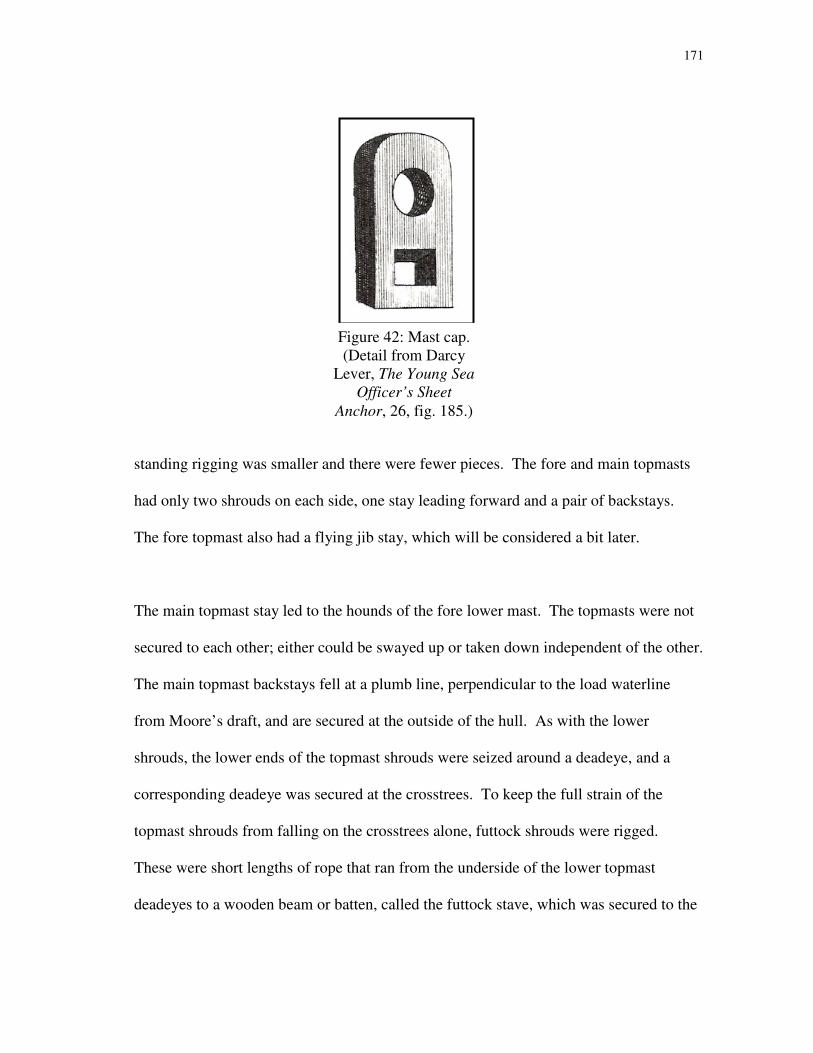
171
standing rigging was smaller and there were fewer pieces. The fore and main topmasts
had only two shrouds on each side, one stay leading forward and a pair of backstays.
The fore topmast also had a flying jib stay, which will be considered a bit later.
The main topmast stay led to the hounds of the fore lower mast. The topmasts were not
secured to each other; either could be swayed up or taken down independent of the other.
The main topmast backstays fell at a plumb line, perpendicular to the load waterline
from Moore’s draft, and are secured at the outside of the hull. As with the lower
shrouds, the lower ends of the topmast shrouds were seized around a deadeye, and a
corresponding deadeye was secured at the crosstrees. To keep the full strain of the
topmast shrouds from falling on the crosstrees alone, futtock shrouds were rigged.
These were short lengths of rope that ran from the underside of the lower topmast
deadeyes to a wooden beam or batten, called the futtock stave, which was secured to the
Figure 42: Mast cap.
(Detail from Darcy
Lever, The Young Sea
Officer’s Sheet
Anchor, 26, fig. 185.)
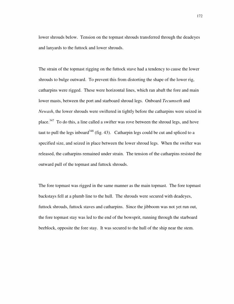
172
lower shrouds below. Tension on the topmast shrouds transferred through the deadeyes
and lanyards to the futtock and lower shrouds.
The strain of the topmast rigging on the futtock stave had a tendency to cause the lower
shrouds to bulge outward. To prevent this from distorting the shape of the lower rig,
catharpins were rigged. These were horizontal lines, which ran abaft the fore and main
lower masts, between the port and starboard shroud legs. Onboard Tecumseth and
Newash, the lower shrouds were swiftered in tightly before the catharpins were seized in
place.347
To do this, a line called a swifter was rove between the shroud legs, and hove
taut to pull the legs inboard348
(fig. 43). Catharpin legs could be cut and spliced to a
specified size, and seized in place between the lower shroud legs. When the swifter was
released, the catharpins remained under strain. The tension of the catharpins resisted the
outward pull of the topmast and futtock shrouds.
The fore topmast was rigged in the same manner as the main topmast. The fore topmast
backstays fell at a plumb line to the hull. The shrouds were secured with deadeyes,
futtock shrouds, futtock staves and catharpins. Since the jibboom was not yet run out,
the fore topmast stay was led to the end of the bowsprit, running through the starboard
beeblock, opposite the fore stay. It was secured to the hull of the ship near the stem.

173
Topgallant Rigging
Since the topmasts and topgallantmasts were made from the same pieces of wood, the
topgallant standing rigging was placed before the topmasts were completely in place.
The rigging was not tensioned, however, until after the topmast rigging had been
secured. Again, being higher in the rig, the topgallantmasts were a smaller diameter than
the top and lower masts below them, and had less rigging. In the case of Tecumseth and
Newash, the main and fore topgallantmasts had one stay and two backstays, but no
shrouds. The topgallant sails were not permanently rigged but were set from the decks.
Without the weight of a topgallant yard and sail aloft, the support of additional standing
rigging was not needed.
Figure 43: Swiftering in shrouds. (Detail from Darcy Lever,
The Young Sea Officer’s Sheet Anchor, 25, fig. 182.)

174
The main topgallant stay led to the fore lower mast cap, and was secured at the fore
trestletrees. The main topgallant backstays fell at a plumb line to the hull, where they
were secured with deadeyes. The fore topgallant stay led to the end of the jibboom, and
could only be tensioned once the jibboom was securely in place. The fore topgallant
backstays also fell at a plumb line to the hull and were secured there.
A short pole stuck out above each topgallant mast. No sails were set on this pole, but a
flag halyard was placed at the truck of the mast and used to hoist signal flags. These
flags were used to communicate between vessels.
Jibboom Rigging
After the topmasts were swayed, the jibboom was rigged. Before it could be secured, a
martingale had to be made and placed. This was a short spar which projected downward
from the forward side of the bowsprit cap, and was raised just before the jibboom was
run out. Because of the low angle and long length of the bowsprit and jibboom, it would
be very difficult to get a downward pull on jibboom stays. By adding the martingale,
and running rigging through holes in its lower end, a better angle could be achieved.
Perhaps counterintuitively, the line that runs from the end of the jibboom, through the
martingale and back to the hull was not called a jibboom stay but a martingale stay.
The jibboom had two shrouds – one on each side of the ship – secured to the hull. The
jibboom also supported the fore topgallantmast. The fore topgallant stay ran through a

175
notch, or dumb sheave, in the end of the jibboom,349
through the martingale, and was
secured to the hull. The inboard end of the jibboom had to be secured as well, to prevent
the boom from sliding down the bowsprit. A heel rope and heel lashing were used for
this purpose.
The flying jib stay occupies a curious point in this discussion of the rigging. Having a
separate stay for the setting of the flying jib prevented the strain of the sail from falling
on any other piece of the rig. An iron ring, or traveler, was placed over the jibboom
before it was hove out. The traveler was circular in shape, with a thimble or shackle
attached at its upper side (fig. 44).350
The flying jib stay ran through this upper ring and
through a sheave in the jibboom. Aloft, the stay ran through a 6-inch (15.24 cm) single
sheave block at the fore topmast hounds. At either end of the stay, two more 6-inch
(15.24 cm) single sheave blocks were secured. A separate line ran through those blocks
and another to create a gun tackle purchase at both ends.351
The tackles meant that the
flying jib stay could be tensioned from its upper or lower end, and the traveler allowed
the stay to be moved along the length of the jibboom. This also meant that the entire
jibboom could be moved inboard, toward the bow of the ship. Two occasions recorded
in Lieutenant Kent’s logbook, kept aboard Newash in 1816 and 1817, mention that the
crew “eased the jib half boom in,” and “eased the jib in.”352
Bringing in the jibboom
might have also been done when the fore topmast was struck, to avoid having a large,
unsecured spar projecting from the hull.
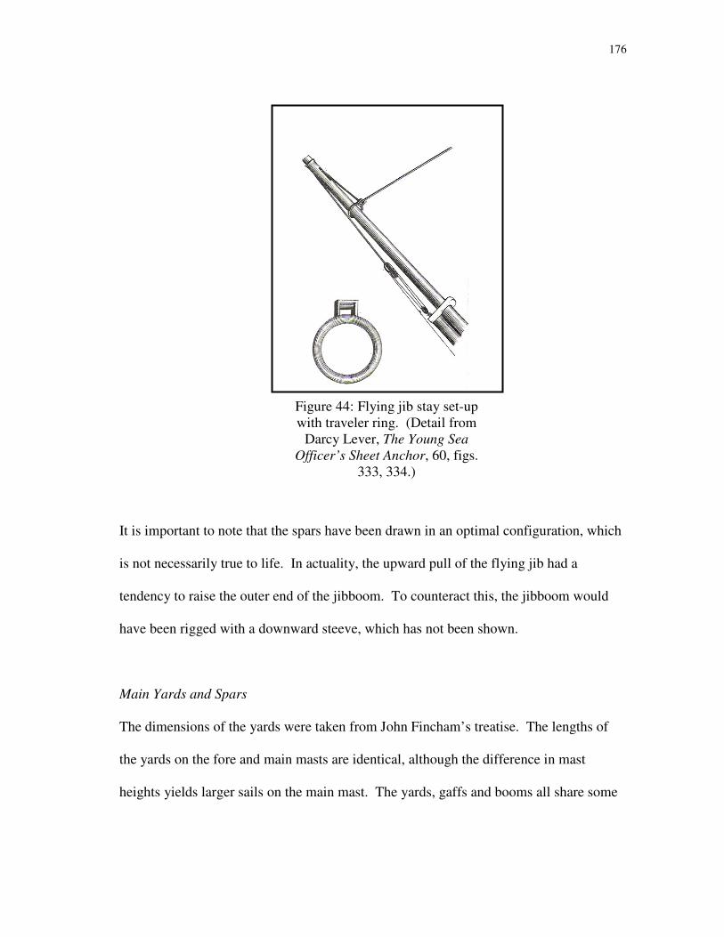
176
It is important to note that the spars have been drawn in an optimal configuration, which
is not necessarily true to life. In actuality, the upward pull of the flying jib had a
tendency to raise the outer end of the jibboom. To counteract this, the jibboom would
have been rigged with a downward steeve, which has not been shown.
Main Yards and Spars
The dimensions of the yards were taken from John Fincham’s treatise. The lengths of
the yards on the fore and main masts are identical, although the difference in mast
heights yields larger sails on the main mast. The yards, gaffs and booms all share some
Figure 44: Flying jib stay set-up
with traveler ring. (Detail from
Darcy Lever, The Young Sea
Officer’s Sheet Anchor, 60, figs.
333, 334.)

177
similar characteristics, both to each other and to other ships of the period, but each is
rigged slightly different. To best illustrate the differences between the spars and the
peculiarities of the rig, the yards and spars will be considered by mast (Table 4).
Table 4: Dimensions of Yards and Spars
What Maximum Diameter Length
Main/Fore Yards353
10 inches (25.41 cm) 38.50 ft, 1.67 ft arm
Main/Fore topsail yards 8 inches (20.33 cm) 31.17 ft, 2.83 ft arm
Main/Fore topgallant yards 6 inches (15.24 cm) 22.75 ft, .92 ft arm
Main Gaff 10 inches (25.41 cm) 24.75 ft
Main Boom 12 inches (30.49 cm) 46.33 ft
Fore Gaff 10 inches (25.41 cm) 22.45 ft
The mainsail was a hoisting sail. The sail stretched between a gaff at the head, or top, of
the sail, and a boom at the foot, or bottom. The gaff was raised with two halyards, a
throat halyard and a peak halyard (fig. 45). The throat halyard assembly included one 9-
inch (22.87 cm) double sheave block and one 9-inch (22.87 cm) single sheave block.354
The double sheave block was lashed to the underside of the main trestletrees and the
single block was lashed to the main gaff. This arrangement could provide three times
the hauling power. The peak halyard was hauled at the same time as the throat halyard
to raise the sail. The peak halyard was rigged with an 8-inch (20.33 cm) double sheave
block and an 8-inch (20.33 cm) single sheave block.355
To allow the peak of the gaff to
be raised higher than the throat, the double sheave block was secured to the after side of
the main mast. The single sheave block was attached to the gaff, approximately three-
quarters of the way to the end. The end of the halyard itself was made off to the end of

178
the gaff. This arrangement of blocks was similar to the double whip type of purchase,
where twice the power is gained.
To keep the gaff under control when lowering the sail, both the throat and the peak had a
downhaul. Each downhaul utilized a 6-inch (15.24 cm) block and line of approximately
0.50-inch (1.27 cm) diameter.356
The throat downhaul block was a single sheave block
while the peak downhaul block had two sheaves. The extra sheave was probably not for
purchase but for a separate flag halyard to be rove. It was not common practice to fly
the Royal Ensign at all times when underway, but the schooners could display it when
they needed to identify themselves as Royal Navy vessels. When the mainsail was set,
Figure 45: Throat and peak
halyard assemblies. (Detail
from Darcy Lever, The Young
Sea Officer’s Sheet Anchor, 43,
fig. 266.)
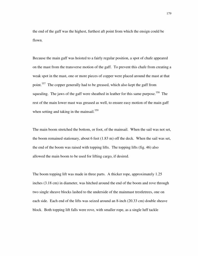
179
the end of the gaff was the highest, furthest aft point from which the ensign could be
flown.
Because the main gaff was hoisted to a fairly regular position, a spot of chafe appeared
on the mast from the transverse motion of the gaff. To prevent this chafe from creating a
weak spot in the mast, one or more pieces of copper were placed around the mast at that
point.357
The copper generally had to be greased, which also kept the gaff from
squealing. The jaws of the gaff were sheathed in leather for this same purpose.358
The
rest of the main lower mast was greased as well, to ensure easy motion of the main gaff
when setting and taking in the mainsail.359
The main boom stretched the bottom, or foot, of the mainsail. When the sail was not set,
the boom remained stationary, about 6 feet (1.83 m) off the deck. When the sail was set,
the end of the boom was raised with topping lifts. The topping lifts (fig. 46) also
allowed the main boom to be used for lifting cargo, if desired.
The boom topping lift was made in three parts. A thicker rope, approximately 1.25
inches (3.18 cm) in diameter, was hitched around the end of the boom and rove through
two single sheave blocks lashed to the underside of the mainmast trestletrees, one on
each side. Each end of the lifts was seized around an 8-inch (20.33 cm) double sheave
block. Both topping lift falls were rove, with smaller rope, as a single luff tackle

180
Figure 46: Boom lift assemblies. (Detail
from Darcy Lever, The Young Sea Officer’s
Sheet Anchor, 44, fig. 269.)
between the double sheave block and an 8-inch (20.33 cm) single sheave block lashed on
deck.
When the mainsail was set, the leeward lift was slackened, to allow the sail to fill
naturally. The weather lift remained taut to prevent the boom from falling if the wind
suddenly shifted or died. To make slacking the leeward lift easier, a lazy guy was
rigged. This was a line that ran through a block made along the run of the topping lift360
(fig. 47). When this line was hauled on, the topping lift would become slack faster and
easier than if the line were simply left hanging loose. The lazy guys ran through 8-inch
(20.33 cm) blocks.361
Like the peak downhaul, one of the blocks had a single sheave

181
Figure 47: Lazy guy assemblies.
(Detail from Darcy Lever, The Young
Sea Officer’s Sheet Anchor, 44,
fig. 268.)
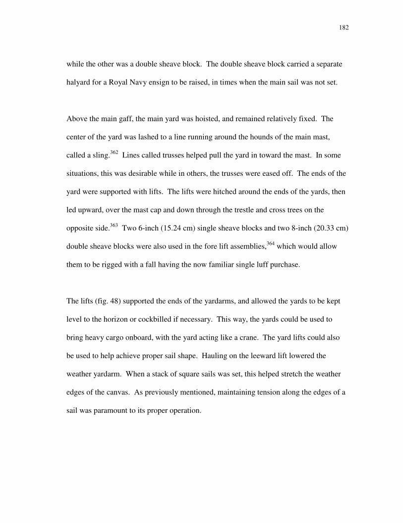
182
while the other was a double sheave block. The double sheave block carried a separate
halyard for a Royal Navy ensign to be raised, in times when the main sail was not set.
Above the main gaff, the main yard was hoisted, and remained relatively fixed. The
center of the yard was lashed to a line running around the hounds of the main mast,
called a sling.362
Lines called trusses helped pull the yard in toward the mast. In some
situations, this was desirable while in others, the trusses were eased off. The ends of the
yard were supported with lifts. The lifts were hitched around the ends of the yards, then
led upward, over the mast cap and down through the trestle and cross trees on the
opposite side.363
Two 6-inch (15.24 cm) single sheave blocks and two 8-inch (20.33 cm)
double sheave blocks were also used in the fore lift assemblies,364
which would allow
them to be rigged with a fall having the now familiar single luff purchase.
The lifts (fig. 48) supported the ends of the yardarms, and allowed the yards to be kept
level to the horizon or cockbilled if necessary. This way, the yards could be used to
bring heavy cargo onboard, with the yard acting like a crane. The yard lifts could also
be used to help achieve proper sail shape. Hauling on the leeward lift lowered the
weather yardarm. When a stack of square sails was set, this helped stretch the weather
edges of the canvas. As previously mentioned, maintaining tension along the edges of a
sail was paramount to its proper operation.
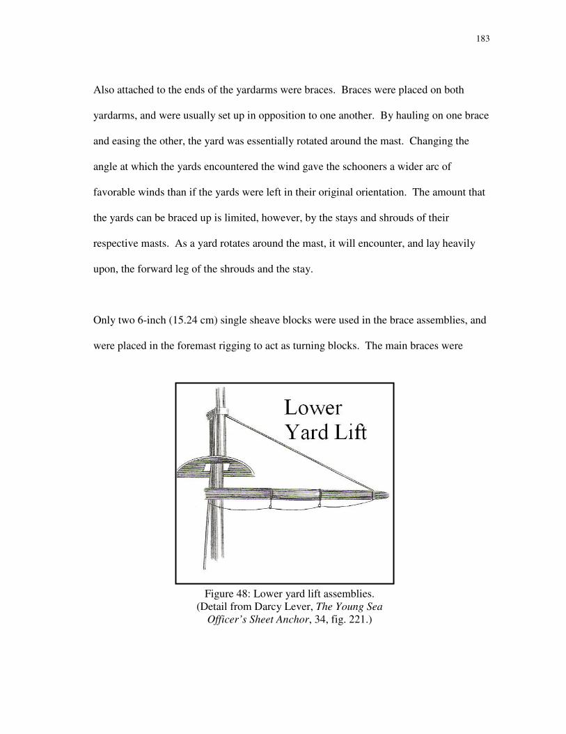
183
Also attached to the ends of the yardarms were braces. Braces were placed on both
yardarms, and were usually set up in opposition to one another. By hauling on one brace
and easing the other, the yard was essentially rotated around the mast. Changing the
angle at which the yards encountered the wind gave the schooners a wider arc of
favorable winds than if the yards were left in their original orientation. The amount that
the yards can be braced up is limited, however, by the stays and shrouds of their
respective masts. As a yard rotates around the mast, it will encounter, and lay heavily
upon, the forward leg of the shrouds and the stay.
Only two 6-inch (15.24 cm) single sheave blocks were used in the brace assemblies, and
were placed in the foremast rigging to act as turning blocks. The main braces were
Figure 48: Lower yard lift assemblies.
(Detail from Darcy Lever, The Young Sea
Officer’s Sheet Anchor, 34, fig. 221.)
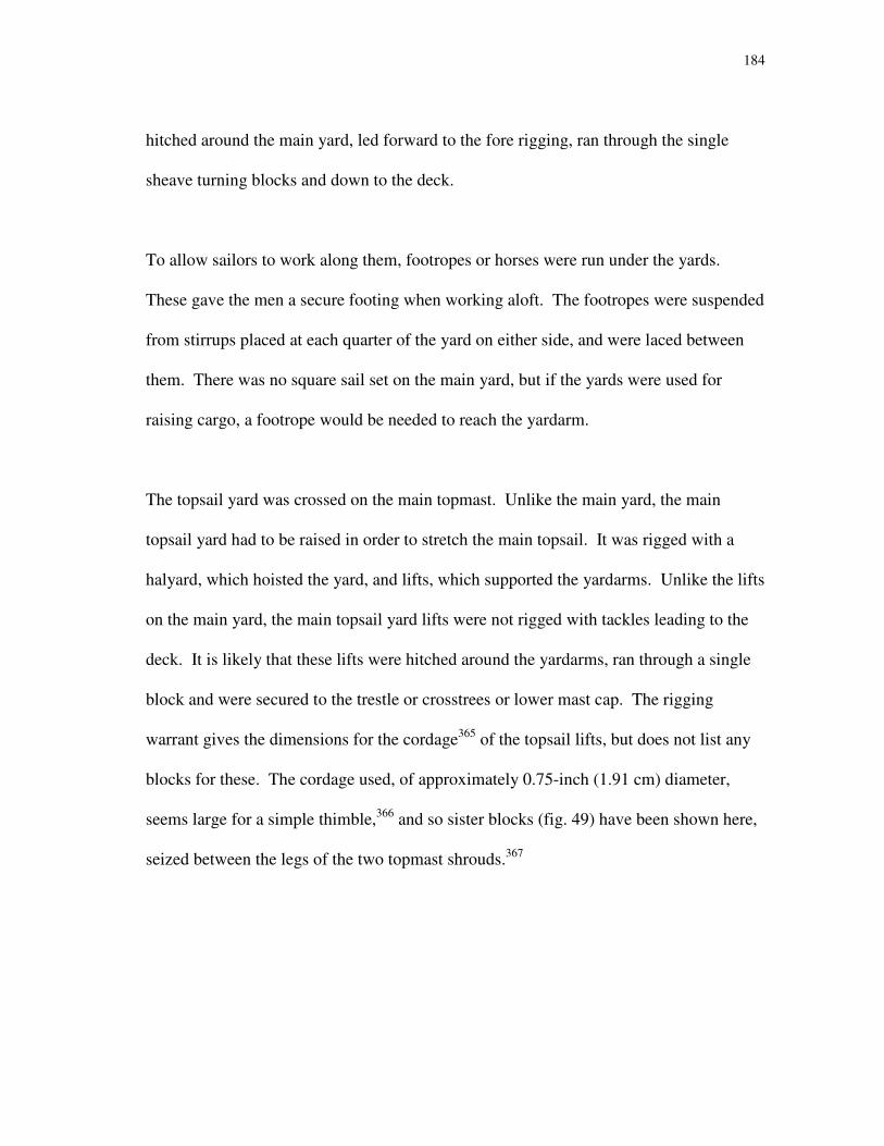
184
hitched around the main yard, led forward to the fore rigging, ran through the single
sheave turning blocks and down to the deck.
To allow sailors to work along them, footropes or horses were run under the yards.
These gave the men a secure footing when working aloft. The footropes were suspended
from stirrups placed at each quarter of the yard on either side, and were laced between
them. There was no square sail set on the main yard, but if the yards were used for
raising cargo, a footrope would be needed to reach the yardarm.
The topsail yard was crossed on the main topmast. Unlike the main yard, the main
topsail yard had to be raised in order to stretch the main topsail. It was rigged with a
halyard, which hoisted the yard, and lifts, which supported the yardarms. Unlike the lifts
on the main yard, the main topsail yard lifts were not rigged with tackles leading to the
deck. It is likely that these lifts were hitched around the yardarms, ran through a single
block and were secured to the trestle or crosstrees or lower mast cap. The rigging
warrant gives the dimensions for the cordage365
of the topsail lifts, but does not list any
blocks for these. The cordage used, of approximately 0.75-inch (1.91 cm) diameter,
seems large for a simple thimble,366
and so sister blocks (fig. 49) have been shown here,
seized between the legs of the two topmast shrouds.367

185
Footropes or horses were rigged on the main topsail yard like the main yard below. The
stirrups were fixed at approximate thirds across each side of the yard, however, since the
topsail yard was shorter than the main yard.
Both fore and main topgallants were set flying, or from the deck, which meant that there
was no standing rigging for these yards. The halyards that hoisted the yards ran through
a sheave in the topgallant mast and both ends ran to the deck. To set the sail, the halyard
was tied to the center of the yard. A downhaul was also attached, usually at one
yardarm. When it was necessary to brace up or in, the topgallant yards simply followed
the topsail yards around, since they had no braces of their own.
Fore Yards and Spars
The foresail, like the mainsail, was a fore-and-aft rigged sail, though it was not rigged to
hoist like the main. Instead, the fore gaff was raised and the sail brailed in to the gaff
and the fore mast. The fore was loose-footed and did not have a boom. Without a
boom, there was no need for topping lifts or lazy jacks. The gaff still required a throat
and peak halyard to hoist it into proper position. These were set up similarly to those on
the main, with the same arrangement of blocks, though the sizes were slightly different.
The fore throat and peak halyards ran through 9-inch (22.87 cm) blocks, where the main
had used 8-inch (20.33 cm) blocks.368
This may have been a matter of available
materials, since each halyard was made of 0.75-inch (1.91 cm) diameter line.369
Unlike
the main gaff, the fore gaff did not have peak and throat downhauls, since it was now
lowered each time the sail was taken in.

186
Figure 49: Sister
block. (Detail
from Darcy Lever,
The Young Sea
Officer’s Sheet
Anchor, 27,
fig. 191.)

187
The foreyard was rigged in a manner similar to the main yard. The yard was secured
with slings at the center, leveled with lifts at the yardarms, and squared or angled to the
mast with braces, which led to the mainmast. The foreyard was also hauled in towards
the mast with trusses, and footropes ran underneath to support sailors.
The fore lower mast did carry a square sail, unlike the main lower mast, and Bushby’s
rigging warrant lists both slings for the yard and a halyard for the sail. This would seem
redundant, since the slings would already support the bulk of the yard and sail. The
halyard may have been rigged for ease in lowering the yard, rather than hoisting it. The
rigging warrant lists only a 6-inch (15.24 cm) single sheave block. This is a rather small
block for the size of the yard, and the line used was only approximately 0.625 inch (1.59
cm) in diameter. Ninety fathoms (540 feet or 164.63 m) of line were available,
though.370
It is possible that the halyard was secured around the mast at the hounds, then
led through a block on the foreyard, through a sheave in the mast, and to the deck.371
The fore topsail yard was rigged in a similar manner to the main topsail yard, with a
halyard, lifts, and braces. The topgallant yard was again set from deck, with a halyard
and downhaul. As on the main, the topgallant yard followed the topsail yard when
bracing up or in.

188
Running Rigging
Some of the running rigging has already been discussed, such as halyards for the gaff
sails, and lifts and braces for the square sails. These were not the only lines which were
used for the setting and adjusting of these sails, though. Most lines used as running
rigging occur in pairs that oppose one another. We have already seen how halyards and
downhauls can be attached to the same point on a spar but work in opposite ways. Most
running rigging has this sort of opponent.
Halyards are used for raising a sail, regardless of whether this involves a yard, gaff, or
neither. On some sails, as we have seen, the halyard is opposed by a downhaul. On
fore-and-aft sails, sheets control the attitude. The attitude may be seen as the way in
which a sail encounters the wind. There is, of course, an optimal way in which a sail
encounters and uses the wind, for maximum effect. This can be achieved by proper
trimming of the sail using the sheet. On fore-and-aft sails, the sheets perform much the
same function as the braces on a square sail. A square sail still has sheets, however. On
a square sail, sheets are used to pull the bottom corners of the sail down towards the
deck, often to the ends of the yardarm below.
Square sails also had several other types of running rigging. One line, called a clueline,
opposed both the halyard and sheet. A clueline ran to the bottom corner, or clue372
of the
sail (fig. 50). When the sheet was in operation, drawing the clue down, the clueline was
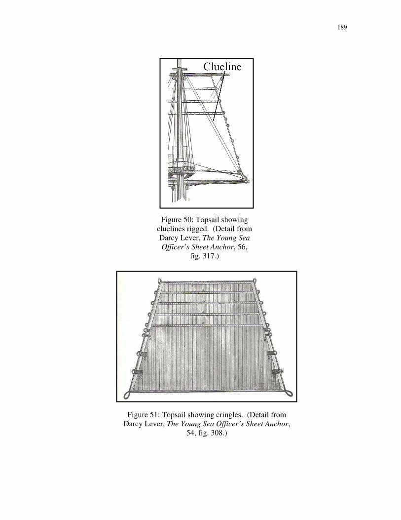
189
Figure 50: Topsail showing
cluelines rigged. (Detail from
Darcy Lever, The Young Sea
Officer’s Sheet Anchor, 56,
fig. 317.)
Figure 51: Topsail showing cringles. (Detail from
Darcy Lever, The Young Sea Officer’s Sheet Anchor,
54, fig. 308.)

190
left slack. To bring a sail back in, the opposite was done: the sheet was left slack and the
clueline was hauled on, which brought the clues back up to the yardarm. The clueline
was usually rove through a block near the center of a yard, or a short distance outboard
on both sides. Because the line ran through a block attached to the yard, it could also be
used to oppose the halyard. If the sheets were left taut, hauling on the clueline actually
pulled the yard down. Newash and Tecumseth’s original rigging configuration included
cluelines on the topsails but not topgallants. Since the topgallants were set from deck, it
was not necessary to have multiple lines that could bring the sail in.
Just as lifts and braces could be used to keep the weather edge of a square sail tight, lines
called bowlines could also be used for this same purpose. Bowlines were comprised of
several short lines called bridles, which are rove through cringles at the vertical edges of
a square sail (fig. 51). Cringles were semi-circles of rope which are attached to the
boltrope, a rope sewn along the edges of a sail. Near the head of the sail, cringles
corresponded with reef bands. On the lower parts of the sail, cringles were used for
bowline bridles. There was always one more cringle than there were bridles. The first
bridle was rove through an eye in the second bridle, and the ends of the first were
attached to the highest two bowline cringles. The second bridle, one end being a splice
to accommodate the first bridle, was rove through an eye in the third bridle and attached
to the third cringle. Any additional bridges were rove in the same manner. Finally, the
last bridle was not attached to the sail at all; an eye at one end accommodated the
previous bridle, and the line ran parallel to the fore topmast stay, through a block at the
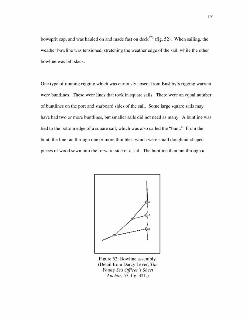
191
bowsprit cap, and was hauled on and made fast on deck373
(fig. 52). When sailing, the
weather bowline was tensioned, stretching the weather edge of the sail, while the other
bowline was left slack.
One type of running rigging which was curiously absent from Bushby’s rigging warrant
were buntlines. These were lines that took in square sails. There were an equal number
of buntlines on the port and starboard sides of the sail. Some large square sails may
have had two or more buntlines, but smaller sails did not need as many. A buntline was
tied to the bottom edge of a square sail, which was also called the “bunt.” From the
bunt, the line ran through one or more thimbles, which were small doughnut-shaped
pieces of wood sewn into the forward side of a sail. The buntline then ran through a
Figure 52: Bowline assembly.
(Detail from Darcy Lever, The
Young Sea Officer’s Sheet
Anchor, 57, fig. 321.)

192
turning block placed high in the rigging, and down to the deck. When the sail was being
set, buntlines were left slack, but they were used to take the sail in. Once a square sail’s
halyard had been eased, hauling on the buntlines brought the bulk of the canvas up to the
yard. This would have made it easier for sailors to furl the sails, as there was less canvas
left to billow and blow about. Buntlines do not appear on Bushby’s rigging warrant.
The small size of the square sails on Tecumseth and Newash may have made buntlines
unnecessary.
The original rigging configuration of Tecumseth and Newash included topgallant sails
which were set flying. The yards were not fixed to the masts, but were hauled from the
deck each time the sail was set. To accomplish this, the sail had a halyard and sheets as
well as a downhaul. The downhaul was likely attached at one of the yardarms. The
halyard was bent to the center of the yard, and nipped about halfway out the opposite
yard arm from where the downhaul was tied. Nipping the halyard off in this manner
allowed the yard to be hauled aloft in a vertical orientation. As the yard neared its
hoisted location, the nipper was untied and the yard crossed to a horizontal position. The
sails’ sheets were probably bent onto the sail when it was aloft, which allowed the
topgallants to set properly. To take the sail in, the sheets were untied, the halyard eased
and the downhaul hauled on until the sail and yard were once again on the deck.
Another interesting configuration in the original sail plan of the schooners can be found
when comparing the gaff-rigged main and foresails. Both were fore-and-aft sails
193
suspended from gaffs, which were hoisted with throat and peak halyards. The bottom
edge, or foot, of the foresail was not attached to any other spar, while the foot of the
mainsail was attached to the main boom. This meant that the entirety of the mainsail and
gaff had to be hoisted each time the sail was set. The sheet was attached to the boom,
which controlled the attitude of the sail. The foresail, however, in its loose-footed
configuration, was set and taken in with several lines called brails. These were small
lines tied off at various points of the after edge, or leech, of the sail. The lines led back
toward the foremast and ran through turning blocks to the deck. When the brails were
hauled on, the foresail could be drawn up and into the foremast, much like a stage
curtain can be drawn back. Because the gaff generally remained in a hoisted location,
two lines called vangs were used to control its movement. The vangs were tied to the
gaff and led to a tackle at deck level. Tension or slack of these vangs allowed the gaff to
pass from one side of the vessel to the other, or kept it secured parallel to the ship’s
centerline.
Discussion: Rigging and Manpower
Much of this rigging reconstruction is speculative. No records of the actual dimensions
of the vessels’ masts and spars could be found, though it is known that such documents
once existed.374
Thomas Bushby’s rigging warrant, however, provides an excellent base
for such speculation. One thing that can be interpreted with a measure of certainty from
the rigging warrant is the way that purchase blocks were used on board.
194
Single sheave blocks were used much more frequently than double sheave blocks, which
limit, to some degree, the possible setup of the rigging. With 30 men on board the
schooners, there was little shortage of muscle power, and purchase blocks were not
frequently needed. The opposite may have been true for a similarly-sized merchant ship.
Unlike a naval vessel, which had a large crew of contracted men, a merchant venture
preferred a small crew. Fewer men consumed less water and provisions, occupied less
precious space within the hull and cost the vessel’s owners less in wages.
Rigs, just like hulls, were designed for specific functions. Within the vehicles that a car-
buyer can choose from are dozens of different types of engines. The same is true for
ships. Some engines seem to be a better fit with certain types of vehicles, while others
are fairly universal. In the same manner, some features of ship rigs match some hull
features better than others. It would not make much sense to put a small engine in a
large truck, just as it would not make sense to put a small, short rig on a large vessel, or
an enormous pile of canvas on a tiny, shallow hull.
For the sake of argument, an ideal sail plan might have consisted of one extremely large
sail.375
The sail must, of course, be massive to utilize the maximum amount of available
wind. One obvious problem of this utopian sail plan was that such a sail would be so
heavy that it would require an enormous crew to set or handle it. The vessel might well
be full of men alone, without any room for cargo, guns or anything else, just to deal with
this sail. One obvious way to alleviate this problem was to split the sail into several
195
smaller sails, on more than one mast. Each sail uses less canvas, less wood, and required
less manpower.
Of course, this could be taken to the opposite extreme. A ship could be rigged with
dozens, even hundreds, of sails small enough to be set by one man alone. Since this one
man could only set one sail at a time, quick maneuvers would be out of the question.
This might have been acceptable in merchant sailing, where tacking and wearing did not
usually happen at a moment’s notice. Naval craft, however, needed to be nimble to
engage and evade an enemy.
Some of the small sails could be combined into a few larger ones, and purchase blocks
added to their rigging, which would multiply an individual’s power. This would permit
a sailor to set fewer, larger sails on his own, which quickened his ability to maneuver.
The trick in designing a rig, then, was to find a balance between sail area, the number of
sails, and the available manpower.
Tecumseth and Newash were Royal Navy vessels with large crews of 30 men. They
could set large sails, and handle them efficiently without the need for extra purchase
blocks. The number of men on board meant that quick maneuvers could be
accomplished, if needed. The rigging configurations were designed for their specific
hulls, hull characteristics and vessel purposes. To this end as well, the sails themselves

196
were made – and later altered – for optimal performance under the specific conditions of
the hulls, rigging and environment.

197
CHAPTER XIII
SAILS AND SAILING
From the rigging plan, it is apparent that these vessels were capable of carrying a
tremendous amount of canvas, especially considering the sharpness and shallowness of
the hull beneath it. The total sail area may be somewhat misleading, however, as there
were few occasions when all canvas was piled on and many more occasions when sails
were taken in or reefed.
When sailing on the Great Lakes, flexibility in terms of sail area was arguably more
important than simple sail area alone. Unlike some other parts of the world with
predominant patterns, the Great Lakes are prone to all types of weather. The months of
October and November bring squalls, strong winds and high seas. The spring carries the
same dangers. The summer can bring months of near-calm conditions. Sailing ships
operating on these waters for an extended period of time needed a certain amount of
flexibility, in terms of sail area, windage and weight aloft, in their rigs. When sailing in
the autumn months, a lofty rig was undesirable. Sail area was kept to a minimum, and
the most universal sails were those that set low and close to the center of the ship. In the
summer, when facing calm seas and light breezes, sailors set nearly every stitch of
canvas they could. Occasionally, the sails highest in the rig could catch a breeze that
could not even be felt at the water’s level. In these cases, the highest sails and those
furthest from the center of the ship were necessary.
198
A good working sail plan might have included the mainsail, foresail, standing jib and
fore and main topsails. In lighter winds or to increase speed topgallants and flying jib
were added. The square sail was used when running before the wind. As winds
increased sail area was reduced, from the outer edges and working inward. Topgallants
and flying jib were taken in. The topsails were reefed or taken in entirely. Reefs could
be taken in the lower sails as well.
In the original sails, there were two reef bands in the topsails, two in the foresail, and at
least one in the mainsail. During the winter of 1815 – 1816, sailors on Tecumseth were
busy making points for several new reef bands. Points are small pieces of line used to
secure the unused part of the sail. A sailmaker added “a balanced Reef in the
Mainsail,”376
third and fourth reef bands in the foresail, two reefs in the standing jib, a
third reef in the fore topsail, and a reef in the square sail.377
An abundance of reefs
allowed the lieutenants commanding the schooners even more control over the amount
of canvas that was set.
Reefing reduces the size of a single sail by essentially folding or rolling one edge and
securing it. The secured edge becomes the new top or bottom of the sail. On the main
and foresails and the standing jib, the bottom edge is rolled up and tied off, creating a
new foot of the sail. On the fore and main topsails, the top of the sail is rolled up and
tied off. A line is run through the upper cringles along the edge of the sail, which draw
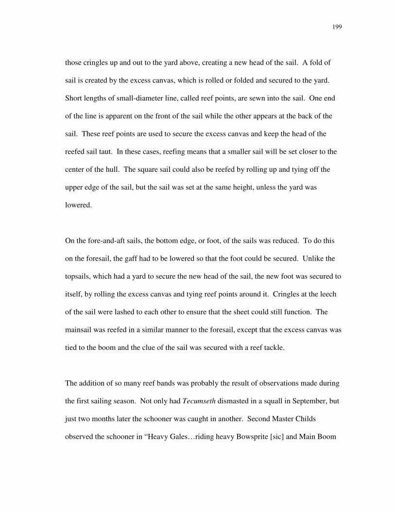
199
those cringles up and out to the yard above, creating a new head of the sail. A fold of
sail is created by the excess canvas, which is rolled or folded and secured to the yard.
Short lengths of small-diameter line, called reef points, are sewn into the sail. One end
of the line is apparent on the front of the sail while the other appears at the back of the
sail. These reef points are used to secure the excess canvas and keep the head of the
reefed sail taut. In these cases, reefing means that a smaller sail will be set closer to the
center of the hull. The square sail could also be reefed by rolling up and tying off the
upper edge of the sail, but the sail was set at the same height, unless the yard was
lowered.
On the fore-and-aft sails, the bottom edge, or foot, of the sails was reduced. To do this
on the foresail, the gaff had to be lowered so that the foot could be secured. Unlike the
topsails, which had a yard to secure the new head of the sail, the new foot was secured to
itself, by rolling the excess canvas and tying reef points around it. Cringles at the leech
of the sail were lashed to each other to ensure that the sheet could still function. The
mainsail was reefed in a similar manner to the foresail, except that the excess canvas was
tied to the boom and the clue of the sail was secured with a reef tackle.
The addition of so many reef bands was probably the result of observations made during
the first sailing season. Not only had Tecumseth dismasted in a squall in September, but
just two months later the schooner was caught in another. Second Master Childs
observed the schooner in “Heavy Gales…riding heavy Bowsprite [sic] and Main Boom
200
under every Dip Sea making a Complete Breach over us.”378
Increasing weather
conditions, particularly towards the end of the sailing season, warranted additional
compensating changes in the rig.
In addition to reef points, which aided in reducing sail area, both vessels were fitted with
a topmast studdingsail, or stuns’l, after the 1815 season.379
This sail was a tall and
narrow sail that set beside the fore topsail, usually to the weather side. Adding a
studdingsail to the sail plan gave the vessel more sail area to work with, when winds
were very light or speed was essential. It does not appear that these sails were used very
often.
Sail Plan and Area
For analysis, a hypothetical sail plan was drawn,380
including all nine sails (fig. 53). The
sail area of each of the sails was calculated, as well as the total (Table 5). The total sail
area of the plan was calculated to be 7284.50 square feet (677.00 m2). This is not
necessarily an accurate representation of the sail area that would be used, since it
includes both the foresail and square sail, which were not commonly used together,
although there were occasions when all possible sail was set. Without the square sail,
the sail area is 5904.50 square feet (548.75 m2). Without the foresail, the sail area was
6023.50 square feet (559.80 m2).
201
Fig
ure
53
: H
yp
oth
etic
al s
ail
pla
n o
f o
rig
inal
rig
.

202
Table 5: Hypothetical Sails and Sail Area
Sail Area
Mainsail 1918.75 square feet (178.32 m2 )
Main Topsail 677 square feet (62.92 m2)
Main Topgallant 275 square feet (25.56 m2)
Gaff Foresail 1225 square feet (113.85 m2)
Fore Topsail 715 square feet (66.45 m2)
Fore Topgallant 300 square feet (27.88 m2)
Square Sail 1344 square feet (124.91 m2)
Standing Jib 379.75 square feet (35.29 m2)
Flying Jib 414 square feet (38.48 m2)
Total 7248.5 square feet (677.00 m2)
This amount of sail area is larger than what might be expected. Howard I. Chapelle
calculated a predicted amount of sail area as 3.6 times that of the “load waterline
section.”381
Assuming that this means the waterplane area, rather than the area of the
midships section below the waterline, this calculation yielded a predicted sail area of
4027.21 square feet (374.28 m2). The sail area, as calculated from the hypothetical sail
plan, is more than 1.5 times that predicted.
From the hypothetical sail plan, several numbers were calculated. The first was the base
of sail, which was measured from the tack of the flying jib to the clue of the mainsail.
Chapelle noticed an overall relationship between the base of sail and the load waterline;
the base of sail was between 1.6 and 1.7 times as long as the load waterline or line of
flotation. Using this formula, a base of sail of was expected between 106.4 feet (32.44
m) and 113.05 feet (34.47 m). Measured from the prepared sail plan, however, the
actual base of sail was 125.5 feet (38.26 m).

203
The midpoint of the base of sail is the same as the fore-and-aft position of the center of
effort for the sail plan. To arrive at the height of the center of effort, Chapelle multiplied
the extreme breadth of a vessel by a factor of 1.12. With this formula, the center of
effort of the given sail plan was calculated as 27.44 feet (8.37 m) above the base of sail.
This placed the center of effort in the middle of the foresail.
The center of effort was 42 feet (12.80 m) above the load waterline, and 13 feet (3.96 m)
forward of the center of the lateral area of the underbody. The latter point was found by
cutting the submerged hull from the sheer profile in the lines drawing and balancing it on
the edge of a knife blade. The point about which such a profile balances was found just
forward of the mainmast step (fig. 54). Chapelle pointed out that the middle of the base
of sail (and, correspondingly, the center of effort of the sails) is often forward of the
center of the lateral area of the underbody. In brigs and schooners, the distance between
the two points is usually between .05 and .063 of the base of sail. These two factors
yielded an expected distance of 6.28 feet (1.91 m) to 7.91 feet (2.41 m).
The distance between the center of the lateral area of the underbody and the midpoint of
the base of sail can also be called the “leading.” High leading gave ships a certain
amount of lee-helm, meaning that the ships had a greater tendency to fall off from the
wind than to round up into it.

204
Fig
ure
54
: C
ente
r o
f la
tera
l b
od
y.
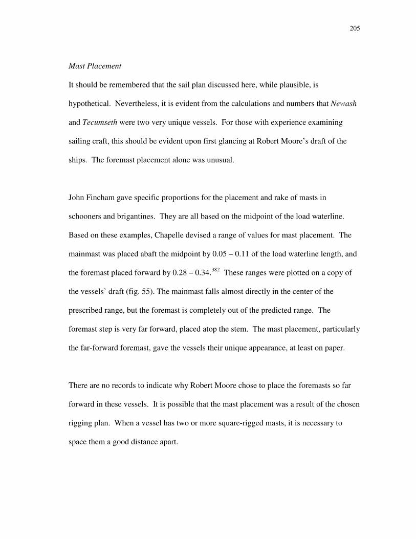
205
Mast Placement
It should be remembered that the sail plan discussed here, while plausible, is
hypothetical. Nevertheless, it is evident from the calculations and numbers that Newash
and Tecumseth were two very unique vessels. For those with experience examining
sailing craft, this should be evident upon first glancing at Robert Moore’s draft of the
ships. The foremast placement alone was unusual.
John Fincham gave specific proportions for the placement and rake of masts in
schooners and brigantines. They are all based on the midpoint of the load waterline.
Based on these examples, Chapelle devised a range of values for mast placement. The
mainmast was placed abaft the midpoint by 0.05 – 0.11 of the load waterline length, and
the foremast placed forward by 0.28 – 0.34.382
These ranges were plotted on a copy of
the vessels’ draft (fig. 55). The mainmast falls almost directly in the center of the
prescribed range, but the foremast is completely out of the predicted range. The
foremast step is very far forward, placed atop the stem. The mast placement, particularly
the far-forward foremast, gave the vessels their unique appearance, at least on paper.
There are no records to indicate why Robert Moore chose to place the foremasts so far
forward in these vessels. It is possible that the mast placement was a result of the chosen
rigging plan. When a vessel has two or more square-rigged masts, it is necessary to
space them a good distance apart.
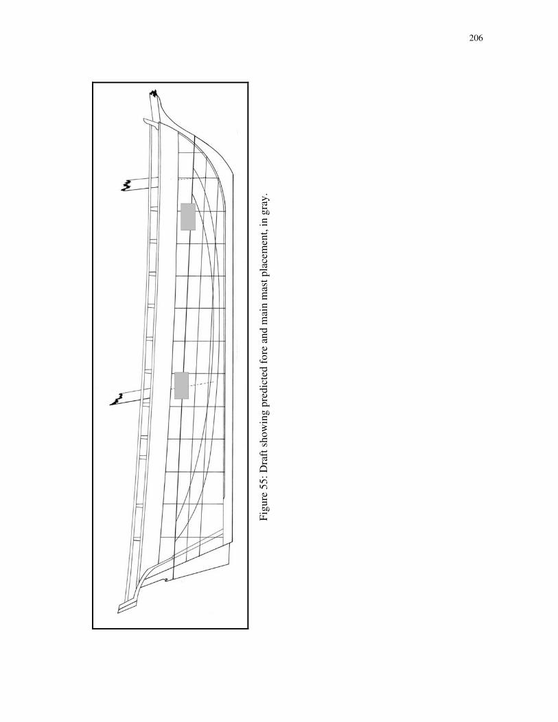
206
Fig
ure
55
: D
raft
sh
ow
ing
pre
dic
ted
fo
re a
nd
mai
n m
ast
pla
cem
ent,
in
gra
y.
207
On most points of sail, square sails are braced into the wind, at least to some degree.
When braced into the wind, air flows on both sides of a square sail and the sail itself
forms an airfoil shape. The airfoil shape provides lift and drive that propels a ship.
When two square-rigged masts are placed close together, the air flowing off the leeward
side of a sail – the side furthest from the wind – on the forward mast can distort sails on
the after mast. The after mast actually receives a breeze, on the wrong side of the sails,
from the mast in front of it. This causes a distortion on the leeward side of the after
sails, reducing their effectiveness.
Another issue that occurred with multiple masts and sails was blanketing. This was the
effect of two sails whose areas overlapped, causing one sail to essentially steal wind
from the other. Perhaps the best example of this effect was of a square-rigged vessel
with the wind dead astern. No matter how the fore sails were braced, those on the main
mast almost always blanketed them.
An ideal sail plan would have consisted of a solid “wall” of canvas, which used all the
wind within its limits. Such a sail plan would have required a single, massive sail
supported by tremendous timbers, which is unrealistic. Instead, shipwrights and naval
architects created ways to use multiple smaller sails to achieve the same effect, while
remaining manageable for those operating them. What is effective on one point of sail,
however, is not always optimal for others. Thus, blanketing can occur, causing some
sails to be distorted or even aback, with the wind entirely on the wrong side, while others
208
are drawing well. These concerns may have caused Moore to ensure that the masts were
placed a good distance apart, which led to the placement show in his draft.
It should be noted that the location of the foremast did yield a fairly balanced sail plan.
The center of effort is a mathematical calculation based on the waterline and beam of a
vessel, rather than the actual areas of the sails. Using that point as a midpoint, the sail
areas forward and aft were calculated. The resultant areas were 3615.5 square feet
(336.01 m2) aft and 3633 square feet (337.64 m
2) forward. Had the foremast been
placed any further aft, that much more sail area of the foresail would have been aft of the
center of effort, potentially affecting how the vessels handled.

209
CHAPTER XIV
RECONSTRUCTION OF THE BRIGANTINE AND SCHOONER II RIGS
Mast placement was also an issue in reconstructing Newash’s second rigging
arrangement, as a brigantine. The rigging change occurred at the end of the 1815 sailing
season, while the vessels were laid up for the winter at Grand River. An account of work
taking place at Grand River during December 1815 includes mention of “cutting new
mast hole” and “shifting three streaks [strakes] of deck [planking] in wake of mast
hole.”383
Since only minimal changes were made to Tecumseth’s rig, it has been assumed that the
new mast hole was cut in the deck of Newash, as part of the shift to a brigantine rig. The
new foremast placement would have changed the geometry of the standing rigging.
New headsails were cut to fit the new arrangement and the old standing and flying jibs
were given to Tecumseth.384
The fore-and-aft rigged foresail could be of little use in the
new rig, and was probably turned over to the other vessel as well.
When the raised hull was identified as Tecumseth, one of the points of evidence was the
lack of a second foremast step. Surviving bolts and wedges indicated a mast step, the
placement of which corresponded closely to the schooners’ draft. Historian C.H.J.
Snider proposed that the foremast was “probably moved aft 10 feet [3.05 m] and
extended”385
when Newash was rigged as a brigantine.

210
A shift of 10 feet (3.05 m) seems a bit excessive. John Fincham’s treatise on rigging
noted that for brigantines, the foremast was placed before the middle of the waterline by
0.300 for one example and 0.294 for a second example.386
Both examples fall within
Chapelle’s prescribed range for a schooner’s foremast placement, but require a shift of
only 5 feet 9 inches (1.75 m) or 6 feet (1.83 m) aft.
Extending either of the masts also seems excessive. True, brigantine rigs were typically
taller than schooner rigs. Fincham’s overall mast heights for a schooner of 24-foot (7.32
m) beam are 92.60 feet (28.23 m) on the mainmast and 87.6 feet (26.71 m) on the fore.
In comparison, using the same beam, a brigantine might be 112.30 feet (34.24 m) tall at
the mainmast and 112 feet (34.15 m) tall at the fore.387
It is important to note that in
both examples the mainmast is taller than the foremast; this is essential in rigging either
a schooner or a brigantine.
It is unlikely that the existing sails, spars and rigging were all scrapped in favor of
completely overhauling the rig. The account of work also mentioned “felling trees for
foremast[,] fore topmast[,] fore topgallant mast[,] fore yard [and] fore topsail yard.”388
It
does not appear that the mainmast was altered, except to rig a gaff topsail instead of a
square topsail and topgallant. Without extending the mainmast assembly, a longer
foremast assembly is unlikely. It seems more befitting the Royal Navy to conserve
resources where possible, reusing sails and spars and changing only what was absolutely

211
necessary. This was probably especially true on Lakes Erie and Huron, with their
distances from resources and supplies, and secondary importance in the post-war years.
As might be expected, Fincham’s schooners typically had longer gaffs and booms than
Fincham’s brigantines, but shorter yards. It is likely that the new yards cut and shaped
for Newash’s brigantine rig were slightly longer than those she had used as a schooner.
The fore yard for a 70 foot-6 inch (21.49 m) common schooner, according to Fincham’s
treatise, was 40.30 feet (12.29 m); the fore topsail yard was 28.80 feet (8.78 m); the fore
topgallant was 18.50 feet (5.64 m).389
In comparison, for a brigantine of the same
length, the fore yard was 40.54 feet (12.36 m); the fore topsail yard was 29.83 feet (9.09
m); the fore topgallant yard was 17.11 feet (5.22 m).390
In addition to longer spars, which would have provided for larger sails, a fore topmast
studdingsail could be set (fig. 56). The foot of the studdingsail was stretched by a small
boom, which was stored atop the foreyard and could be pushed outboard for use. The
bottom corners of the sail were tensioned and secured with a tack and a sheet,
which led to the deck. The head of the sail was attached to a short yard that was hoisted
from the deck by a studdingsail halyard.391

212
Figure 56: Studdingsails.
(Detail from Darcy Lever,
The Young Sea Officer’s
Sheet Anchor, 65,
fig. 351.)
213
The Conversion Factor
Historian and artist Rowley Murphy, writing on the recovery of Tecumseth in 1954,
proposed that the conversion of Newash from a schooner to a brigantine rig would have
been accompanied by a change in standing rigging. Murphy noted that “[t]he usual
practice in rigging vessels of brigantine or barkentine rig was, and is, to stay their
foremasts with more shrouds than were used on the mainmast.”392
Murphy theorized
that “at least four and possibly five shrouds” were needed to stabilize a brigantine’s
foremast.393
Murphy may be correct, and there was a blacksmith employed at the Grand
River establishment who could have made the necessary ironwork for an additional
chainplate or two. Bushby also requested 30 fathoms (180 feet or 54.88 m) of 4.50-inch
(11.43 cm) rope, only slightly smaller than the 5-inch (12.70 cm) rope used for the fore
shrouds.394
The account of work at the establishment, however, lists the smith “repairing
stoves and stove pipes…making bolts for bolting steps of fore mast and tressle [sic]
trees…[and] making hoops[,] staples and hooks to yard.”395
No mention was made of
chainplates, chains, or deadeyes. The remains of what appear to be chainplates were
found during Erich Heinold’s 1998 investigations on the wreck of Newash. Only three
such pieces were found, though the associated timber remains are fragmentary.
It should be remembered that Newash was converted to a brigantine, rather than
constructed as one. Some changes were certainly made, but probably not as many as if
the hull had been completely stripped down and an entirely new rig designed. It is
difficult, if not impossible, to determine exactly which items were retained and which
214
were altered. As schooners, Newash and Tecumseth were capable of carrying three
square-rigged sails on their foremasts. On 11 October 1815, Newash’s logbook recorded
sailing with “all sail,” including square sail, fore topsail and fore topgallant.396
The
foresail was set as well, giving the schooner a significant amount of canvas on her
foremast. Even with longer yards and larger sails, it seems doubtful that the brigantine
fore stack had more sail area than the schooner fore stack. Without an increase in sail
area, it is questionable whether the vessel would have required additional standing
rigging.
Gaff Topsails and Main Topmast Staysails
The extant mainmast assembly could be altered to accommodate a gaff topsail quite
easily. British ships at this time commonly used lug-rigged gaff topsails, the sail being
suspended between the main gaff at the foot, and a short spar called a lug at the head.397
Bushby’s rigging warrant lists a gaff topsail halyard, sheet and downhaul. One 8-inch
(20.33 cm) single sheave block was used for the halyard, with two 8-inch (20.33 cm)
single sheave blocks for the sheet and a 6-inch (15.24 cm) single sheave block for the
downhaul. This arrangement indicates that the sail was set flying. The halyard ran
through the halyard block, which was affixed near the truck of the topgallant pole. The
lug of the sail was bent on to the halyard before the sail could be set. One of the sheet
blocks was placed at the peak of the main gaff, with the other acting as a turning block
near the throat. The downhaul was probably tied to the clue of the sail, like the sheet,
and ran through a block along the lug. When the sail was taken in, the sheet was cast off

215
and the downhaul hauled upon, which acted to brail the sail in, similar to the schooner
foresail. The downhaul continued to be hauled on as the halyard was eased, bringing the
sail and lug down to the deck. This assembly was probably used for both vessels, as gaff
topsails were added to both the brigantine and revamped schooner rigs.
Tecumseth’s second schooner rig varied only slightly from the original arrangement. A
trysail mast was stepped on deck immediately abaft the foremast. The jaws of the fore
gaff and boom fit around the trysail mast, while the squaresail yard was attached to the
foremast itself. This allowed the sails to be operated more independently of each other.
The square-rigged main topsail and main topgallant were removed, as with Newash, in
favor of a main gaff topsail and a main topmast staysail.
E.W.C.R. Owen seems to have been enamored with the gaff topsail and main topmast
staysail configuration. The arrangement was specifically chosen for Sauk and Huron
when those schooners were refitted for the Royal Navy.398
In October 1815, E.W.C.R.
Owen wrote of his “desire that in all the future equipments of these and other schooners
on the Lakes, square main topsails shall not be issued, but that gaff main topsails and
main topmast staysails shall be given them in lieu.”399

216
CHAPTER XV
CONCLUSIONS AND COMMENT
An individual vessel offers a unique insight into not only her specific purpose but
potentially even to the political climate at the time of her inception. Newash and
Tecumseth are particularly interesting, because of the light they shed on a very particular
and little-known period of time. The Napoleonic Wars and the War of 1812 demanded
certain ships, and the resultant vessels are fairly well documented. In almost every case,
the possibility or certainty of war is evident. These were gun ships and row galleys,
ships that were off the stocks in mere weeks, and were often fragile platforms laden with
enormous artillery. War was the principle of the time. When war was removed,
however, the paradigms that dictated thinking and building had to shift. Perhaps the
most interesting aspect of the two schooners discussed here is their presentation of how
that shift occurred.
Unlike the prevalent attitude of the shipbuilders’ war on the Great Lakes, the size of
Tecumseth and Newash indicates that bigger was no longer thought to be better.
E.W.C.R. Owen specified two schooners of 130 tons were to be built. Robert Moore
designed them to be a little larger, a little sleeker, and a little faster. Even while
designed as sharp hulls, their primary purpose of transporting troops and stores was
evident. Newash and Tecumseth were beamier than their War of 1812 counterparts.
Their shallow, wide hulls would have made the vessels dangerous and unsafe on ocean
passages, but Lakes Erie and Huron offered a different scenario entirely.
217
The original configuration of the ships had them equipped with four guns apiece and
lofty rigs. Square sails were placed on both masts. Large crews allowed the schooners
to set heavy sails with manpower alone. Yet even in their short sailing careers, both
vessels’ rigs were altered. The new rigs were originally implemented as experiments.
With the war over, concepts of sails and sailing that had been germinating could be put
to a test. The most prominent change in these two new rigs was the abandonment of
square sails on the mainmast in favor of fore-and-aft rigged gaff topsail and main
topmast staysail.
The shift in sails is striking. Why bother to change half of the rig after only half of a
sailing season? One reason may be the changing political atmosphere on the Great
Lakes. The hard-fought War of 1812 was over. Little territory had changed hands, and
that had changed right back. Hard feelings remained, but neither side was eager to
reenter the bloody stages of battle again. Except for occasional spikes of enmity,
tensions cooled after the Treaty of Ghent.
When Newash and Tecumseth were first envisioned, peace was a novelty. Though
officially transports, the schooners were to be heavily armed and ready to fight at a
moments’ notice. In case fighting erupted, the schooners were rigged with square sails
on the fore and main masts.
218
Square sails were a feature of vessels sailing downwind, such as trade-wind sailing
vessels, and ships at war. The balance of square sails, particularly when placed on more
than one mast, allows a ship to slow down, stop herself, drift sideways or go backwards.
When engaging an enemy, they can maneuver quickly and in tight quarters. Fore-and-
aft sails are useful on more points of sail, but vessels carrying them are slower to react,
and slower to turn. Fore-and-aft vessels are best used in evading an enemy, running a
blockade, outpointing another ship or sailing fast.
Had post-war strain and stress flared anywhere on Lake Huron or Lake Erie, Newash and
Tecumseth could have sailed there quickly, and acted as battleships when needed.
During their first season, however, it became increasingly apparent that while tensions
still existed, diplomacy rather than deadly force would be used. Newash and
Tecumseth’s square sails became antiquated. The vessels were re-rigged with a more
“peaceful” sail plan.
Elsewhere on the lakes, the shifting politics became evident as well. British military
outposts were reduced in size and number. A number of men were given acreage in
Canada, populating the frontier with loyal settlers and offering a base from which to
draft recruits should the need arise. Fewer men were required on the establishments, and
on the ships as well.

219
With fewer men working the same rig, each man would need to do a little more work.
Adapting Tecumseth and Newash’s rigs for a smaller crew would have been a matter of
simply exchanging a few single sheave blocks for double sheave blocks and increasing
the purchase power of the tackles. Without a square-rigged main topsail, there was no
yard aloft to be raised, or brought down in case of poor weather. The gaff topsail was
set from the deck, as was the fore topgallant. The sails had a number of reef bands,
allowing them to be shortened in case of inclement weather. The regular company was
often augmented by men being transported, who could be counted on to haul on a line if
needed.
The Rush-Bagot agreement rendered Newash and Tecumseth obsolete after very short
sailing careers. Ironically, interactions with American ships occurring onboard the ships
themselves affected the way the agreement was framed. The vessels had acted as
architects of their own demises. William Bourchier had thought his post on Lake Erie a
distant and obscure corner of Canada; the harbor where the schooners were retired truly
was. Disarmed and neglected as peace prevailed, the ships simply rotted away.
The rebirth of interest in Great Lakes naval history that led to the relocation and removal
of Tecumseth in 1953 ignored the shadowy story of post-war people and politics. The
people of Penetanguishene wanted to recover a warship, preferably a relic from the
Battle of Lake Erie. The skeletal remains failed to live up to pre-salvage enthusiasm.

220
In recent years, however, with the introduction of nautical archaeology and the
incorporation of various disciplines that it demands, the story of Tecumseth and Newash
has come to light. The two vessels are really fascinating and their history, while short, is
intriguing; analysis of the architecture and rigging shows that they were remarkable
vessels in many ways. The two hulls have offered a truly unique point from which to
gather information on the variety of areas that influence different aspects of a singular
vessel design.

221
NOTES
1 For full text of the treaty, see Appendix A.
2 L. Farrington, “The Decline of Naval Bases on the Lakes of Canada,” 3.
3 James Lucas Yeo to Prevost, 25 February 1815. LAC, Admiralty Fonds, ADM 1/2262.
4 Bathurst to Drummond, 10 January 1815, in William Wood, Select British Documents of the Canadian
War of 1812, vol. III, part I, 507.
5 There are two Owen brothers – Commodore Edward William Campbell Rich Owen and Captain
William Fitz William Owen – who factor significantly into this story. To avoid confusion, their initials
and last name – E.W.C.R. Owen and W.F.W. Owen – will be used throughout the text to distinguish
between them.
6 The title “Senior Officer on the Lakes of Canada” was used in most correspondence addressed to
E.W.C.R. Owen, though he signed his letters “Commodore in Command.” See LAC, Admiralty Fonds,
ADM 1/2262-2266.
7 E.W.C.R. Owen, “Estimate of the Force Required for the War Establishment on the Lakes of Canada,” 5
November 1815. LAC, Admiralty Fonds, ADM 1/2264. Since the Royal Navy apparently had no
intention of carrying out these plans, Owen’s estimate can only be considered hypothetical.
8 A Naval Encyclopaedia, 1881, s.v. “Ordnance.”
9 E.W.C.R. Owen to Dobbs, 17 July 1815. LAC, Record Group 8, Series III, Vol. 3.
10 Lieutenant Colonel Robert McDouall was to recommend a site for the new military post, but the site
had to be approved by a naval officer before construction could begin. J. Harvey to E.W.C.R. Owen, 27
March 1815. LAC, Admiralty Fonds, ADM 1/2262.
11 While Lakes Erie, Huron and Michigan are all geographically connected, the Royal Navy had little
interest or need to venture into Lake Michigan, and most of its efforts were confined to the other bodies of
water.
12 E.W.C.R. Owen to Croker, 28 November 1816. LAC, Admiralty Fonds, ADM 1/2264.
13 The Lachine locks opened in 1825, the Welland Canal (between Lakes Erie and Ontario) in 1829 and
the Rideau Canal in 1832.
14 Robert Hall to Navy Board, 29 November 1814. LAC, Admiralty Fonds, ADM 106/1997.
15 James Lucas Yeo to Prevost, 25 February 1815. LAC, Admiralty Fonds, ADM 1/2262.
16 E.W.C.R. Owen to Croker, 25 March 1815. LAC, Admiralty Fonds, ADM 1/2262.
17 Robert McDouall to Forster, 15 March 1815, in William Wood, Select British Documents of the
Canadian War of 1812, vol. III, part I, 532.
18 Robinson to Prevost, 14 November 1814, in William Wood, Select British Documents of the Canadian
War of 1812, vol. III, part I, 503.

222
19 Edward Collier to Yeo, 11 March 1815. LAC, Admiralty Fonds, ADM 1/2262.
20 E.W.C.R. Owen to Drummond, 6 April 1815, PRO, Record Group 8, Series IC, vol. 734.
21 Draft of Schooners. PRO, Admiralty Fonds, ADM, Reg. No. 4562, Box 64.
22 Henry Kent to E.W.C.R. Owen, 11 June 1815. LAC, Admiralty Fonds, ADM 1/2262.
23 Robert Hall to Navy Board, 18 May 1815. LAC, Admiralty Fonds, ADM 106/1997.
24 Henry Kent to E.W.C.R. Owen, 11 June 1815. LAC, Admiralty Fonds, ADM 1/2262. A work party of
24 Royal Marines at Street’s Creek was employed rafting timber from the Chippewa to the shipyard.
25 E.W.C.R. Owen, “Observations relative to the defence [sic] of the Lake Frontier continued from
enclosures to Letters 36, 37 and 48,” 5 November 1815. LAC, Admiralty Fonds, ADM 1/2264.
26 E.W.C.R. Owen, “Observations relative to the defence [sic] of the Lake Frontier continued from
enclosures to Letters 36, 37 and 48,” 5 November 1815. LAC, Admiralty Fonds, ADM 1/2264.
27 In spite of the fact that only Huron and Sauk were actually outfitted on the banks of the Chippewa
River, Chippewa (also spelled “Chippawa” and “Chippeway”) is given as the site of the construction of
Newash and Tecumseth in several Admiralty documents. Robert Hall to Navy Board, 18 May 1815.
LAC, Admiralty Fonds, ADM 106/1997.
28 E.W.C.R. Owen to Croker, 19 April 1815. LAC, Admiralty Fonds, ADM 1/2262.
29 E.W.C.R. Owen to Croker, 19 April 1815. LAC, Admiralty Fonds, ADM 1/2262.
30 Robert Hall to Navy Board, 18 May 1815. LAC, Admiralty Fonds, ADM 106/1997.
31 Draft of Schooners. PRO, Admiralty Fonds, ADM, Reg. No. 4562, Box 64.
32 “Statement of Force on Lake Erie and Huron [sic],” 1 June 1815. LAC, Admiralty Fonds, ADM
1/2262.
33 E.W.C.R. Owen to Drummond, 6 April 1815. PRO, Record Group 8, Series IC, vol. 734.
34 For a discussion of what it means to be a “sharp” vessel and the hull characteristics of these ships, see
Chapter 11.
35 Draft of Schooners. PRO, Admiralty Fonds, ADM, Reg. No. 4562, Box 64.
36 Draft of Schooners. PRO, Admiralty Fonds, ADM, Reg. No. 4562, Box 64.
37 The spelling “fo’c’sle” is also commonly used.
38 “Statement of Force on Lake Erie and Huron [sic],” 1 June 1815. LAC, Admiralty Fonds, ADM
1/2262.
39 “Statement of Force on Lake Erie and Huron [sic],” 1 June 1815. LAC, Admiralty Fonds, ADM
1/2262.

223
40 Robert Hall to Navy Board, 18 May 1815. LAC, Admiralty Fonds, ADM 106/1997.
41 This change may have been made because it allowed the ships to carry one size shot, which could be
used in any of the guns. There was one gunner at the Lake Erie establishment, but he could not be present
on each of the vessels in the fleet. Had any of the schooners actually seen combat action, it would have
been easier to carry one size shot that could be used universally.
42 For an excellent history of the carronade, see Spencer C. Tucker, “The Carronade,” 65 – 70.
43 E.W.C.R. Owen to Drummond, 4 April 1815. PRO, Record Group 8, Series IC, vol. 734.
44 Robert Hall to Navy Board, 18 May 1815. LAC, Admiralty Fonds, ADM 106/1997.
45 E.W.C.R. Owen, “General Instructions for the Commander of the Naval Establishment upon Lake
Erie,” 12 October 1815. LAC, Admiralty Fonds, ADM 1/2264.
46 E.W.C.R. Owen, “General Instructions for the Commander of the Naval Establishment upon Lake
Erie,” 12 October 1815. LAC, Admiralty Fonds, ADM 1/2264.
47 E.W.C.R. Owen to the Captain Commanding the Naval Establishment at Isle Aux Noix, 15 June 1815.
LAC, Admiralty Fonds, ADM 106/1997.
48 Officer’s Service Record, Captain Thomas Bushby. PRO, Admiralty Fonds, ADM 196/3.
49 Officer’s Service Record, Captain Henry Kent. PRO, Admiralty Fonds, ADM 196/5, part 1.
50 H.F. Pullen, March of the Seamen, 16.
51 H.F. Pullen, March of the Seamen, 17.
52 Edwards Laws to Walker, 4 July 1815. LAC, Record Group 8, Series III, vol. 5.
53 “A General Table of Day Pay, for the Workmen in His Majesty’s Dock and Rope Yards, Established by
Admiralty Order,” 19 March 1815. LAC, Record Group 8, Series III, vol. 1.
54 E.W.C.R. Owen, “Observations relative to the defence [sic] of the Lake Frontier continued from
enclosures to Letters 36, 37 and 48,” 5 November 1815. LAC, Admiralty Fonds, ADM 1/2264.
55 “Log of the Proceedings on Board HM Schooner/Brigantine Newash on Lake Erie, 13 August 1815 –
30 June 1817,” 13 August 1815. PRO, Admiralty Fonds, ADM 51/2607.
56 “Log of the Proceedings on Board HM Schooner/Brigantine Newash on Lake Erie, 13 August 1815 –
30 June 1817,” 14 August 1815. PRO, Admiralty Fonds, ADM 51/2607.
57 “Log of the Proceedings on Board HM Schooner/Brigantine Newash on Lake Erie, 13 August 1815 –
30 June 1817,” 15 August 1815. PRO, Admiralty Fonds, ADM 51/2607.
58 Edward Laws to Navy Board, 13 September 1815. LAC, Admiralty Fonds, ADM 106/1997; Edward
Laws to Payne, 12 September 1815. LAC, Admiralty Fonds, ADM 106/1997; Robert Hall to Navy Board,
26 November 1815. LAC, Admiralty Fonds, ADM 106/1997.
59 For a description of a schooner’s rigging elements and sails, see Appendix B.

224
60 Thomas Bushby, “An Account of Rigging and Sails Belonging to His Majesty’s Schooner Newash,” 19
September 1815. LAC, Record Group 8, Series III, vol. 5.
61 In reality, it is redundant to say “forward-leading stays” since the nature of a stay is that it leads
forward. To avoid any confusion between “stays” and “backstays” in this discussion, however, the
terminology has been used.
62 A similar situation occurred on H.M.S. Princess Charlotte in 1814, which was heaved down over the
course of three days to remove cleats which remained on her bottom after launching. Henry Kent, “The
Extraordinary March of Lieutenant Henry Kent,” 9.
63 “Log of the Proceedings on Board HM Schooner/Brigantine Newash on Lake Erie, 13 August 1815 –
30 June 1817,” 21 August 1815. PRO, Admiralty Fonds, ADM 51/2607.
64 Thomas Bushby, “An Account of the Rigging and Sails Belonging to His Majesty’s Schooner
Newash,” 19 September 1815. LAC, Record Group 8, Series III, vol. 5.
65 Charles Payne to Laws, 25 August 1815. LAC, Admiralty Fonds, Record Group 8, Series III, vol. 4,
Number 2.
66 “Log of the Proceedings on Board HM Schooner/Brigantine Newash on Lake Erie, 13 August 1815 –
30 June 1817” 26 August 1815. PRO, Admiralty Fonds, ADM 51/2607.
67 Henry Kent, “Log of H.M. Brigantine Newash on the Lakes Erie and Huron Between the 14th of
November 1816 and 30th June 1817,” 14 November 1816. LAC, Admiralty Fonds, ADM 52/4548.
68 See James Childs, “Log of the Proceedings onboard H.M. Schooner Tecumseth on Lake Erie Between
the 13th of August 1815 and 13th of November 1816,” 30 August 1815, 31 August 1815, 1 September
1815. LAC, Admiralty Fonds, ADM 52/3933; “Log of the Proceedings on Board HM
Schooner/Brigantine Newash on Lake Erie, 13 August 1815 – 30 June 1817,” 30 August 1815, 31 August
1815. PRO, Admiralty Fonds, ADM 51/2607.
69 James Childs, “Log of the Proceedings onboard H.M. Schooner Tecumseth on Lake Erie Between the
13th of August 1815 and 13th of November 1816,” 30 August 1815. LAC, Admiralty Fonds, ADM
52/3933.
70 Three logbooks record the events of the morning of 2 September 1815, but do not agree on the exact
wind direction. Captain Bourchier recorded a northerly wind, Second Master Childs a north-northeasterly
wind, and Lieutenant Bushby a south-southwesterly breeze. Bushby is the only one to record a sea
direction, observing a southwesterly swell. This makes the south-southwesterly breeze which Bushby
records seem more likely. It also seems more appropriate to the situation described, since a northerly or
north-northeasterly wind would not have had the fetch, or long stretch of sea room, necessary to kick up
the swell that occurred.
71 “Log of the Proceedings on Board HM Schooner/Brigantine Newash on Lake Erie, 13 August 1815 –
30 June 1817,” 2 September 1815. PRO, Admiralty Fonds, ADM 51/2607.
72 William Bourchier, “Journal of the Proceedings of His Majesty’s Ships Viz: Tecumseth From 12th
August 1815 to 30th June 1817, Laurel from 21st February 1811 to 21st December 1814,” 2 September
1815. LAC, Admiralty Fonds, ADM 51/2502.

225
73 The rank of “Second Master” seems to be much less common than “Master’s Mate,” though both titles
refer to an individual subordinate to the vessel’s master, who carried out the more menial of the master’s
tasks. In most cases, the “Second Master” or “Master’s Mate” was apprenticed to the Master, a useful step
for those who would eventually pursue higher naval ranks. John Masefield, Sea Life in Nelson’s Time, 68.
74 James Childs, “Log of the Proceedings onboard H.M. Schooner Tecumseth on Lake Erie Between the
13th of August 1815 and 13th November 1816,” 2 September 1815. LAC, Admiralty Fonds, ADM
52/3933.
75 Gusts are here assumed to be one and half times greater than the sustained winds of these conditions.
Using a mean wind speed at Force 5 of 19 knots (21.87 mph), gusts for the same conditions would reach
28.5 knots (32.79 mph).
76 “Log of the Proceedings on Board HM Schooner/Brigantine Newash on Lake Erie, 13 August 1815 –
30 June 1817,” 2 September 1815. PRO, Admiralty Fonds, ADM 51/2607.
77 “Log of the Proceedings on Board HM Schooner/Brigantine Newash on Lake Erie, 13 August 1815 –
30 June 1817,” 2 September 1815. PRO, Admiralty Fonds, ADM 51/2607.
78 “Log of the Proceedings on Board HM Schooner/Brigantine Newash on Lake Erie, 13 August 1815 –
30 June 1817,” 5 September 1815. PRO, Admiralty Fonds, ADM 51/2607.
79 E.W.C.R. Owen, “General Instructions for the Commander of the Naval Establishment upon Lake
Erie,” 12 October 1815. LAC, Admiralty Fonds, ADM 1/2264.
80 E.W.C.R. Owen to Drummond, 10 July 1815. PRO, Record Group 8, Series IC, vol. 735.
81 James Childs, “Log of the Proceedings onboard H.M. Schooner Tecumseth on Lake Erie Between the
13th of August 1815 and 13th of November 1816,” 29 June 1816. LAC, Admiralty Fonds, ADM 52/3933.
82 James Childs, “Log of the Proceedings onboard H.M. Schooner Tecumseth on Lake Erie Between the
13th of August 1815 and 13th of November 1816,” 18 June 1816. LAC, Admiralty Fonds, ADM 52/3933.
83 James Childs, “Log of the Proceedings onboard H.M. Schooner Tecumseth on Lake Erie Between the
13th of August 1815 and 13th of November 1816,” 16 August 1816. LAC, Admiralty Fonds, ADM
52/3933.
84 Navy Office to the Respective Officers of His Majesty’s Yard at Quebec, 12 June 1815. LAC, Record
Group 8, Series III, vol. 1.
85 James Childs, “Log of the Proceedings onboard H.M. Schooner Tecumseth on Lake Erie Between the
13th of August 1815 and 13th of November 1816,” 9 April 1816. LAC, Admiralty Fonds, ADM 52/3933.
86 James Childs, “Log of the Proceedings onboard H.M. Schooner Tecumseth on Lake Erie Between the
13th of August 1815 and 13th of November 1816,” 15 June 1816. LAC, Admiralty Fonds, ADM 52/3933.
87 James Childs, “Log of the Proceedings onboard H.M. Schooner Tecumseth on Lake Erie Between the
13th of August 1815 and 13th November 1816,” 23 December 1815. LAC, Admiralty Fonds, ADM
52/3933.
88 James Childs, “Log of the Proceedings onboard H.M. Schooner Tecumseth on Lake Erie Between the
13th of August 1815 and 13th of November 1816,” 13 June 1816. LAC, Admiralty Fonds, ADM 52/3933.

226
89 E.W.C.R. Owen to Laws, 5 October 1815. LAC, Record Group 8, Series III, vol. 5.
90 E.W.C.R. Owen to W.F.W. Owen, 18 November 1815. LAC, Admiralty Fonds, ADM 1/2264.
91 E.W.C.R. Owen to Croker, 2 December 1815. LAC, Admiralty Fonds, ADM 1/2264.
92 For examples of these specific provisions, see James Childs, “Log of the Proceedings onboard H.M.
Schooner Tecumseth on Lake Erie Between the 13th of August 1815 and 13th of November 1816,” 17 July
1816, 27 July 1816, 28 July 1816 and 26 October 1816. LAC, Admiralty Fonds, ADM 52/3933.
93 James Childs, “Log of the Proceedings onboard H.M. Schooner Tecumseth on Lake Erie Between the
13th of August 1815 and 13th of November 1816,” 9 June 1816. LAC, Admiralty Fonds, ADM 52/3933.
94 W.F.W. Owen to Respective Captains and Commanders of His Majesty’s Ships and Vessels on the
Lake Ontario, no date. LAC, Admiralty Fonds, ADM 1/2265.
95 W.F.W. Owen to Baumgardt, no date. LAC, Admiralty Fonds, ADM 1/2265.
96 “Weekly Returns, 1st – 31st January 1816, Lake Huron.” LAC, Admiralty Fonds, ADM 1/2265.
97 “Weekly Returns, 2nd October to 30 November 1815 on Lake Huron.” LAC, Admiralty Fonds, ADM
1/2265; “Weekly Returns, 1st – 31st January 1816, Lake Huron.” LAC, Admiralty Fonds, ADM 1/2265.
98 James Childs, “Log of the Proceedings onboard H.M. Schooner Tecumseth on Lake Erie Between the
13th of August 1815 and 13th of November 1816,” 26 July 1816. LAC, Admiralty Fonds, ADM 52/3933.
99 James Childs, “Log of the Proceedings onboard H.M. Schooner Tecumseth on Lake Erie Between the
13th of August 1815 and 13th of November 1816,” 3 April 1816. LAC, Admiralty Fonds, ADM 52/3933.
100 Thomas Bushby, “An Account of Rigging and Sails Belonging to His Majesty’s Schooner Newash,”
19 September 1815. LAC, Record Group 8, Series III, vol. 5.
101 Twenty-five feet (7.62 m) is 1/240 of a nautical mile (6000 ft or 1829.27 m). Correspondingly, 15
seconds is 1/240 of an hour (60 minutes or 3600 seconds).
102 If using a 15-second glass, the number of knots counted equals the ships speed in nautical miles per
hour, or knots. If using a 30-second glass, the number of knots must be divided by two, or an additional
log line must be prepared with knots 50 feet (15.24 m) apart. William Brady, writing on American naval
practices in 1847, used a 28-second glass and a log line with marks every 47.60 feet (14.51 m). Brady
seemed concerned with measuring the fractions of each knot (in eighths) but his method seems
unnecessarily complex. William Brady, The Kedge-Anchor or Young Sailor’s Assistant, 148.
103 Thomas Bushby, “An Account of Rigging and Sails Belonging to His Majesty’s Schooner Newash,”
19 September 1815. LAC, Record Group 8, Series III, vol. 5.
104 Thomas Bushby, “An Account of Rigging and Sails Belonging to His Majesty’s Schooner Newash,”
19 September 1815. LAC, Record Group 8, Series III, vol. 5.
105 James Childs, “Log of the Proceedings onboard H.M. Schooner Tecumseth on Lake Erie Between the
13th of August 1815 and 13th of November 1816,” 8 October 1816. LAC, Admiralty Fonds, ADM
52/3933.

227
106 James Childs, “Log of the Proceedings onboard H.M. Schooner Tecumseth on Lake Erie Between the
13th of August 1815 and 13th of November 1816,” 17 May 1816. LAC, Admiralty Fonds, ADM 52/3933.
107 James Childs, “Log of the Proceedings onboard H.M. Schooner Tecumseth on Lake Erie Between the
13th of August 1815 and 13th of November 1816,” 29 October 1816. LAC, Admiralty Fonds, ADM
52/3933.
108 James Childs, “Log of the Proceedings onboard H.M. Schooner Tecumseth on Lake Erie Between the
13th of August 1815 and 13th of November 1816,” 12 June 1816. LAC, Admiralty Fonds, ADM 52/3933.
109 James Childs, “Log of the Proceedings onboard H.M. Schooner Tecumseth on Lake Erie Between the
13th of August 1815 and 13th of November 1816,” 28 April 1816. LAC, Admiralty Fonds, ADM
52/3933.
110 W.F.W. Owen to Bourchier, 20 May 1816. LAC, Admiralty Fonds, ADM 1/2266.
111 James Childs, “Log of the Proceedings onboard H.M. Schooner Tecumseth on Lake Erie Between the
13th of August 1815 and 13th of November 1816,” 1 September 1816. LAC, Admiralty Fonds, ADM
52/3933.
112 Thomas Bushby, “An Account of Rigging and Sails Belonging to His Majesty’s Schooner Newash,”
19 September 1815. LAC, Record Group 8, Series III, vol. 5.
113 James Childs, “Log of the Proceedings onboard H.M. Schooner Tecumseth on Lake Erie Between the
13th of August 1815 and 13th of November 1816,” 23 April 1816. LAC, Admiralty Fonds, ADM
52/3933.
114 It is regular practice on the U.S. Brig Niagara, a modern re-interpretation of a war of 1812 vessel, to
haul the ship to short stay by hand, and employ the brig’s capstan only when breaking the anchor out of
the lake bottom. Captain Walter Rybka, master of Niagara, has stated that the momentum gathered by the
hull as the anchor rode is hauled on often causes the ship to sail over her anchor, breaking it out in the
process. In this case, the capstan is used only as a safety precaution. Walter Rybka, pers. comm.
115 “Log of the Proceedings on Board HM Schooner/Brigantine Newash on Lake Erie, 13 August 1815 –
30 June 1817,” 27 September 1815. PRO, Admiralty Fonds, ADM 51/2607.
116 Thomas Bushby to Bourchier, 9 November 1815. PRO, Record Group 8, Series IC, vol. 736.
117 E.W.C.R. Owen to Baker, 23 October 1815. LAC, Admiralty Fonds, ADM 1/2264.
118 Enclosed in E.W.C.R. Owen to Baker, 23 October 1815. LAC, Admiralty Fonds, ADM 1/2264.
119 Thomas Jefferson to Crawford, 14 February 1815, with Postscript dated 26 February. “American
Memory, The Thomas Jefferson Papers.”
120 James Jackson to Bourchier, 16 November 1815. LAC, Admiralty Fonds, ADM 1/2265.
121 Laws to Navy Board, 18 May 1816. LAC, Admiralty Fonds, ADM 106/1997.
122 E.W.C.R. Owen to Baker, 9 September 1815. LAC, Admiralty Fonds, ADM 1/2263.
123 E.W.C.R. Owen to Baker, 9 September 1815. LAC, Admiralty Fonds, ADM 1/2263.

228
124 Alexander Vidal to E.W.C.R. Owen, 8 November 1815. LAC. Admiralty Fonds, ADM 1/2265.
125 Alexander Vidal to E.W.C.R. Owen, 16 October 1815, Enclosed in E.W.C.R. Owen to Baker, 6
November 1815. LAC, Admiralty Fonds, ADM 1/2265.
126 Sir Anthony Baker had been one of the commissioners to ratify the Treaty of Ghent.
127 Alexander Vidal to E.W.C.R. Owen, 16 October 1815, Enclosed in E.W.C.R. Owen to Baker, 6
November 1815. LAC, Admiralty Fonds, ADM 1/2265. Including the attorney’s fee, Vidal was required
to pay $778.85.
128 E.W.C.R. Owen to Baker, 6 November 1815. LAC, Admiralty Fonds, ADM 1/2265.
129 E.W.C.R. Owen to Baker, 6 November 1815. LAC, Admiralty Fonds, ADM 1/2265.
130 E.W.C.R. Owen to Baker, 6 November 1815. LAC, Admiralty Fonds, ADM 1/2265.
131 Richard Rush to Bagot, 4 April 1817. LAC, Bagot Papers, Military Group 24, Series A13, vol. 14.
The situation was still unsettled in April 1817.
132 See W.F.W. Owen to Hambly, 16 December 1815; Sir Gordon Drummond to W.F.W. Owen, 6
January 1816; W.F.W. Owen to Sir Gordon Drummond, 17 January 1816a and 17 January 1816b. LAC,
Admiralty Fonds, ADM 1/2265.
133 W.F.W. Owen to Drummond, 17 January 1816a. LAC, Admiralty Fonds, ADM 1/2265.
134 E.W.C.R. Owen, “Observations relative to the defence [sic] of the Lake Frontier continued from
enclosures to Letters 36, 37 and 48,” 5 November 1815. LAC, Admiralty Fonds, ADM 1/2264.
135 E.W.C.R. Owen, “Observations relative to the defence [sic] of the Lake Frontier continued from
enclosures to Letters 36, 37 and 48,” 5 November 1815. LAC, Admiralty Fonds, ADM 1/2264.
136 W.F.W. Owen to Drummond, 17 January 1816b. LAC, Admiralty Fonds, ADM 1/2265.
137 Robert Hall to Navy Board, 12 March 1815. LAC, Admiralty Fonds, ADM 106/1997.
138 John Aldersly to W.F.W. Owen, Enclosed in Thomas Payne to Croker, no date. LAC, Admiralty
Fonds, ADM 1/2263.
139 E.W.C.R. Owen to Croker, 8 October 1815. LAC, Admiralty Fonds, ADM 1/2263.
140 Burlington Bay is on the western shore of Lake Ontario, near the modern city of Hamilton, Ontario.
W.F.W. Owen to E.W.C.R. Owen, 20 July 1815. LAC, Admiralty Fonds, ADM 1/2263.
141 W.F.W. Owen to E.W.C.R. Owen, 20 July 1815. LAC, Admiralty Fonds, ADM 1/2263.
142 United States Army Corps of Engineers, “Detroit District – Detroit River.” This phenomena is not
limited to the Grand River entrance. The whole of Lake Erie is affected by certain winds. In modern
times, the U.S. Army Corps of Engineers has recorded a surface difference of 14.50 feet (4.42 m) from
one end of the lake to the other. Several of the smaller adjacent waterways are likewise affected, such as
Sandusky Bay and the Detroit River.

229
143 John Harris and John Aldersly to E.W.C.R. Owen, 10 June 1815. PRO, Record Group 8, Series IC,
vol. 370.
144 E.W.C.R. Owen to Laws, 5 August 1815. LAC, Record Group 8, Series III, vol. 5. These barracks
were apparently not complete when the vessels arrived, as a working party from Tecumseth’s crew was
sent “building Barracks” after the vessel arrived at Grand River. James Childs, “Log of the Proceedings
onboard H.M. Schooner Tecumseth on Lake Erie Between the 13th of August 1815 and the 13th
November 1816,” 15 November 1815. LAC, Admiralty Fonds, ADM 52/3933.
145 John Aldersly to W.F.W. Owen, Enclosed in Thomas Payne to Croker, no date. LAC, Admiralty
Fonds, ADM 1/2263.
146 W.F.W. Owen to Croker, 21 February 1816. LAC, Admiralty Fonds, ADM 1/2265. Sauk and
Confiance wintered at Drummond Island, while Surprize was at Nottawasaga.
147 A “quarterman of shipwrights” is a supervisory role, similar to a foreman.
148 E.W.C.R. Owen, “Revised Naval Civil Establishments,” 6 October 1815. LAC, Record Group 8,
Series III, vol. 5.
149 E.W.C.R. Owen, “General Instructions for the Commander of the Naval Establishment upon Lake
Erie,” 12 October 1815. LAC, Admiralty Fonds, ADM 1/2264.
150 E.W.C.R. Owen, “General Instructions for the Commander of the Naval Establishment upon Lake
Erie,” 12 October 1815. LAC, Admiralty Fonds, ADM 1/2264.
151 E.W.C.R. Owen, “General Instructions for the Commander of the Naval Establishment upon Lake
Erie,” 12 October 1815. LAC, Admiralty Fonds, ADM 1/2264.
152 Since the “mole” would have been used to lay the ships up for the winter, it was presumably similar to
a dock or pier.
153 E.W.C.R. Owen to W.F.W. Owen, 5 November 1815. LAC, Admiralty Fonds, ADM 1/2264.
154 James Childs, “Log of the Proceedings onboard H.M. Schooner Tecumseth on Lake Erie Between the
13th of August 1815 and the 13th November 1816,” 10 November 1815, 11 November 1815, 12
November 1815, 13 November 1815. LAC, Admiralty Fonds, ADM 52/3933.
155 John Jewell, “A Return of all the Boats and Batteaux Belonging to His Majesty’s Naval Establishment
Lake Erie and Not Attached to Vessels,” 31 December 1815. LAC, Admiralty Fonds, ADM 1/2265.
156 James Childs, “Log of the Proceedings onboard H.M. Schooner Tecumseth on Lake Erie Between the
13th of August 1815 and 13th November 1816,” 12 November 1815. LAC, Admiralty Fonds, ADM
52/3933.
157 James Childs, “Log of the Proceedings onboard H.M. Schooner Tecumseth on Lake Erie Between the
13th of August 1815 and 13th November 1816,” 13 November 1815. LAC, Admiralty Fonds, ADM
52/3933.
158 James Childs, “Log of the Proceedings onboard H.M. Schooner Tecumseth on Lake Erie Between the
13th of August 1815 and 13th November 1816,” 18 November 1815. LAC, Admiralty Fonds, ADM
52/3933.

230
159 James Childs, “Log of the Proceedings onboard H.M. Schooner Tecumseth on Lake Erie Between the
13th of August 1815 and 13th November 1816,” 20 December 1815, 21 December 1815. LAC, Admiralty
Fonds, ADM 52/3933.
160 W.F.W. Owen to the Respective Captains and Commanders of His Majesty’s Ships and Vessels on
the Lakes of Canada,” 8 April 1816. LAC, Admiralty Fonds, ADM 1/2266.
161 James Childs, “Log of the Proceedings onboard H.M. Schooner Tecumseth on Lake Erie Between the
13th of August 1815 and 13th November 1816,” 29 November 1815. LAC, Admiralty Fonds, ADM
52/3933.
162 James Childs, “Log of the Proceedings onboard H.M. Schooner Tecumseth on Lake Erie Between the
13th of August 1815 and 13th November 1816,” 22 September 1815. LAC, Admiralty Fonds, ADM
52/3933.
163 John Jewell, “Return of Work at Grand River,” 31 December 1815. LAC, Admiralty Fonds, ADM
1/2265.
164 John Jewell, “Return of Work at Grand River,” 31 December 1815. LAC, Admiralty Fonds, ADM
1/2265.
165 John Jewell, “Return of Work at Grand River,” 31 December 1815. LAC, Admiralty Fonds, ADM
1/2265.
166James Childs, “Log of the Proceedings onboard H.M. Schooner Tecumseth on Lake Erie Between the
13th of August 1815 and 13th November 1816,” 7 May 1816. LAC, Admiralty Fonds, ADM 52/3933.
167 E.W.C.R. Owen, “General Instructions No. 2 for the Commander of the Naval Establishment upon
Lake Erie,” 12 October 1815. LAC, Admiralty Fonds, ADM 1/2264.
168 James Childs, “Log of the Proceedings onboard H.M. Schooner Tecumseth on Lake Erie Between the
13th of August 1815 and 13th November 1816,” 7 December 1815. LAC, Admiralty Fonds, ADM
52/3933.
169 James Childs, “Log of the Proceedings onboard H.M. Schooner Tecumseth on Lake Erie Between the
13th of August 1815 and 13th November 1816,” 18 January 1816. LAC, Admiralty Fonds, ADM
52/3933.
170 James Childs, “Log of the Proceedings onboard H.M. Schooner Tecumseth on Lake Erie Between the
13th of August 1815 and 13th November 1816,” 10 March 1816, 12 March 1816, 23 March 1816. LAC,
Admiralty Fonds, ADM 52/3933.
171 James Childs, “Log of the Proceedings onboard H.M. Schooner Tecumseth on Lake Erie Between the
13th of August 1815 and 13th November 1816,” 23 March 1816, 30 March 1816, 2 April 1816, 3 April
1816. LAC, Admiralty Fonds, ADM 52/3933.
172 James Childs, “Log of the Proceedings onboard H.M. Schooner Tecumseth on Lake Erie Between the
13th of August 1815 and 13th November 1816,” 4 April 1816. LAC, Admiralty Fonds, ADM 52/3933.
173 James Childs, “Log of the Proceedings onboard H.M. Schooner Tecumseth on Lake Erie Between the
13th of August 1815 and 13th November 1816,” 18 April 1816. LAC, Admiralty Fonds, ADM 52/3933.

231
174 James Childs, “Log of the Proceedings onboard H. M. Schooner Tecumseth on Lake Erie Between the
13th of August 1815 and 13th November 1816,” 20 April 1816, 21 April 1816, 22 April 1816. LAC,
Admiralty Fonds, ADM 52/3933.
175 James Childs, “Log of the Proceedings onboard H.M. Schooner Tecumseth on Lake Erie Between the
13th of August 1815 and 13th November 1816,” 22 April 1816. LAC, Admiralty Fonds, ADM 52/3933.
176 James Childs, “Log of the Proceedings onboard H.M. Schooner Tecumseth on Lake Erie Between the
13th of August 1815 and 13th November 1816,” 22 April 1816. LAC, Admiralty Fonds, ADM 52/3933.
177 James Childs, “Log of the Proceedings onboard H.M. Schooner Tecumseth on Lake Erie Between the
13th of August 1815 and 13th November 1816,” 23 April 1816. LAC, Admiralty Fonds, ADM 52/3933.
178 James Childs, “Log of the Proceedings onboard H.M. Schooner Tecumseth on Lake Erie Between the
13th of August 1815 and 13th November 1816,” 24 April 1816. LAC, Admiralty Fonds, ADM 52/3933.
179 James Childs, “Log of the Proceedings onboard H.M. Schooner Tecumseth on Lake Erie Between the
13th of August 1815 and 13th November 1816,” 27 April 1816. LAC, Admiralty Fonds, ADM 52/3933.
180 James Childs, “Log of the Proceedings onboard H.M. Schooner Tecumseth on Lake Erie Between the
13th of August 1815 and 13th November 1816,” 27 April 1816. LAC, Admiralty Fonds, ADM 52/3933.
181 The Royal Navy’s daily rum ration continued until 1970.
182 James Childs, “Log of the Proceedings onboard H.M. Schooner Tecumseth on Lake Erie Between the
13th of August 1815 and 13th November 1816,” 27 April 1816. LAC, Admiralty Fonds, ADM 52/3933.
183 “Log of the Proceedings on Board HM Schooner/Brigantine Newash on Lake Erie, 13 August 1815 –
30 June 1817,” 28 April 1816, 29 April 1816. PRO, Admiralty Fonds, ADM 51/2607.
184 “Log of the Proceedings on Board HM Schooner/Brigantine Newash on Lake Erie, 13 August 1815 –
30 June 1817,” 29 April 1816. PRO, Admiralty Fonds, ADM 51/2607.
185 “Log of the Proceedings on Board HM Schooner/Brigantine Newash on Lake Erie, 13 August 1815 –
30 June 1817,” 30 April 1816. PRO, Admiralty Fonds, ADM 51/2607.
186 “Log of the Proceedings on Board HM Schooner/Brigantine Newash on Lake Erie, 13 August 1815 –
30 June 1817,” 1 May 1816. PRO, Admiralty Fonds, ADM 51/2607.
187 W.F.W. Owen to Bourchier, 31 March 1816. LAC, Admiralty Fonds, ADM 1/2266.
188 L. Farrington, The Decline of Naval Bases on the Lakes of Canada, 1815 – 1834, 10.
189 Henry Kent, “Log of H.M. Brigantine Newash on the Lakes Erie and Huron Between the 14th of
November 1816 and 30th June 1817,” 17 November 1816. LAC, Admiralty Fonds, ADM 52/4548.
190 Henry Kent, “Log of H.M. Brigantine Newash on the Lakes Erie and Huron Between the 14th of
November 1816 and 30th June 1817,” 13 December 1816. LAC, Admiralty Fonds, ADM 52/4548.
191 See Henry Kent, “Log of H.M. Brigantine Newash on the Lakes Erie and Huron Between the 14th of
November 1816 and 30th June 1817,” 25 December 1816, 16 January 1817, 20 January 1817, 28 January
1817, 31 January 1817, 10 February 1817. LAC, Admiralty Fonds, ADM 52/4548.

232
192 Robert Hall to Navy Board, 26 September 1816. LAC, Admiralty Fonds, ADM 106/1997.
193 Officer’s Service Record, Captain Thomas Bushby. PRO, Admiralty Fonds, ADM 196/13.
194 Officer’s Service Record, Lieutenant Abraham Whitehead. PRO, Admiralty Fonds, ADM 196/6.
195 W.F.W. Owen to Drummond, 21 April 1816. LAC, Admiralty Fonds, ADM 1/2266.
196 William Bourchier, “Extract of a letter from Captain W. Bourchier Commanding His Majesty’s Naval
Establishment on Lake Erie to Captain W.F.W. Owen, Senior Officer on the Lakes of Canada, dated
Grand River 2 March 1816.” LAC, Admiralty Fonds, ADM 1/2266.
197 William Bourchier, “Extract of a letter from Captain W. Bourchier Commanding His Majesty’s Naval
Establishment on Lake Erie to Captain W.F.W. Owen, Senior Officer on the Lakes of Canada, dated
Grand River 2 March 1816.” LAC, Admiralty Fonds, ADM 1/2266.
198 William Bourchier to Baumgardt, enclosed in William Baumgardt to Bagot, 5 September 1816. LAC,
Bagot Papers, Military Group 24, Series A13, vol. 1.
199 W.F.W. Owen, “Extract of a letter from Captain [W.F.W.] Owen to Lieutenant Governor Gore, dated
Kingston Naval Yard 21 March 1816.” LAC, Admiralty Fonds, ADM 1/2266.
200 W.F.W. Owen, “Extract of a letter from Captain [W.F.W.] Owen to Lieutenant Governor Gore, dated
Kingston Naval Yard 21 March 1816.” LAC, Admiralty Fonds, ADM 1/2266.
201 Darcy Boulton, “Case for the Opinion of the Attourney [sic] General respecting Seizures or Searches
on the Lakes in Canada by the Navy.” LAC, Admiralty Fonds, ADM 1/2266.
202 William Bourchier to the Commanding Officers of H.M. Vessels on Lake Erie, 23 July 1816. LAC,
Bagot Papers, Military Group 24, Series A13, vol. 1.
203 William Bourchier to the Commanding Officers of H.M. Vessels on Lake Erie, 23 July 1816, enclosed
in William Baumgardt to Bagot, 5 September 1816. LAC, Bagot Papers, Military Group 24, Series A13,
vol. 1.
204 Henry Kent to Bourchier, 28 July 1816, enclosed in William Baumgardt to Bagot, 5 September 1816.
LAC, Bagot Papers, Military Group 24, Series A13, vol. 1.
205 See James Childs, “Log of the Proceedings onboard H.M. Schooner Tecumseth on Lake Erie Between
the 13th of August 1815 and 13th November 1816,” 6 July 1816, 7 July 1816. LAC, Admiralty Fonds,
ADM 52/3933; Henry Kent to Bourchier, 28 July 1816, enclosed in William Baumgardt to Bagot, 5
September 1816. LAC, Bagot Papers, Military Group 24, Series A13, vol. 1.
206 Charles Bagot to Sherbrooke and Commodore E.W.C.R. Owen, 14 August 1816. LAC, Bagot Papers,
Military Group 24, Series A13, vol. 1.
207 Henry Kent to Bourchier, 28 July 1816, enclosed in William Baumgardt to Bagot, 5 September 1816.
LAC, Bagot Papers, Military Group 24, Series A13, vol. 1.

233
208 This wording is significant, as the border between the United States and Canada was to follow the
middle of the border lakes, and split the main channel of passage between them. Interestingly, today the
channel between Bois Blanc Island and the Canadian mainland is used for north-bound traffic. The
channel to the west of Bois Blanc Island is used for south-bound traffic. Bois Blanc Island (now called
Boblo Island) itself is Canadian.
209 Lewis Cass to the Officer Commanding His Britannic Majesty’s Schooner Tecumseth, n.d., enclosed
in William Baumgardt to Bagot, 5 September 1816. LAC, Bagot Papers, Military Group 24, Series A13,
vol. 1.
210 Lewis Cass to the Officer Commanding His Britannic Majesty’s Schooner Tecumseth, n.d., enclosed
in William Baumgardt to Bagot, 5 September 1816. LAC, Bagot Papers, Military Group 24, Series A13,
vol. 1.
211 William Baumgardt to Bourchier, 5 September 1816, enclosed in William Baumgardt to Bagot, 5
September 1816. LAC, Bagot Papers, Military Group 24, Series A13, vol. 1.
212 James Monroe to Bagot, 2 August 1816. LAC, Bagot Papers, Military Group 24, Series A13, vol. 14.
213 James Monroe to Bagot, 2 August 1816. LAC, Bagot Papers, Military Group 24, Series A13, vol. 14.
214 W.F.W. Owen to Baumgardt, 3 September 1816, enclosed in William Baumgardt to Bagot, 5
September 1816. LAC, Bagot Papers, Military Group 24, Series A13, vol. 1.
215 W.F.W. Owen to Baumgardt, 3 September 1816, enclosed in William Baumgardt to Bagot, 5
September 1816. LAC, Bagot Papers, Military Group 24, Series A13, vol. 1.
216 W.F.W. Owen to Baumgardt, 3 September 1816, enclosed in William Baumgardt to Bagot, 5
September 1816. LAC, Bagot Papers, Military Group 24, Series A13, vol. 1.
217 James Monroe to Bagot, 2 August 1816. LAC, Bagot Papers, Military Group 24, Series A13, vol. 14.
218 Charles Bagot, “Bagot Agreement,” 28 April 1816. LAC, Bagot Papers, Military Group 24, Series
A13, vol. 14.
219 For full text of the agreement, see Appendix C.
220 Henry Kent, “Log of H.M. Brigantine Newash on the Lakes Erie and Huron Between the 14th of
November 1816 and 30th June 1817,” 18 June 1817. LAC, Admiralty Fonds, ADM 52/4548.
221 Abraham Whitehead, “Log of the Proceedings of H.M. Schooner Tecumseth Commencing November
14th 1816 and ending June 30th 1817,” 19 June 1817. LAC, Admiralty Fonds, ADM 51/2072.
222 Henry Kent, “Log of H.M. Brigantine Newash on the Lakes Erie and Huron Between the 14th of
November 1816 and 30th June 1817,” 21 June 1817. LAC, Admiralty Fonds, ADM 52/4548.
223 Abraham Whitehead, “Log of the Proceedings of H.M. Schooner Tecumseth Commencing November
14th 1816 and ending June 30th 1817,” 21 June 1817. LAC, Admiralty Fonds, ADM 51/2072.
224 Henry Kent, “Log of H.M. Brigantine Newash on the Lakes Erie and Huron Between the 14th of
November 1816 and 30th June 1817,” 23 June 1817, 24 June 1817. LAC, Admiralty Fonds, ADM
52/4548.

234
225 Henry Kent, “Log of H.M. Brigantine Newash on the Lakes Erie and Huron Between the 14th of
November 1816 and 30th June 1817,” 24 June 1817. LAC, Admiralty Fonds, ADM 52/4548.
226 Henry Kent, “Log of H.M. Brigantine Newash on the Lakes Erie and Huron Between the 14th of
November 1816 and 30th June 1817,” 30 June 1817. LAC, Admiralty Fonds, ADM 52/4548; Abraham
Whitehead, “Log of the Proceedings of H.M. Schooner Tecumseth Commencing November 14th 1816 and
ending June 30th 1817,” 30 June 1817. LAC, Admiralty Fonds, ADM 51/2072.
227 “Survey of His Majesty’s Buildings and Wharves at Penetanguishene, on Lake Huron,” 22 September
1820. LAC, Admiralty Fonds, ADM 106/1997.
228 Robert Barrie to his mother, 14 September 1819. Royal Military College, Robert Barrie
Correspondence 1819 – 1828.
229 Robert Barrie to Commissioners, 25 August 1819, quoted in L. Farrington, “The Decline of Naval
Bases on the Lakes of Canada, 1815 – 1834,” 6.
230 Robert Adams, William Wilson, and C. Thomas, “A Survey of His Majesty’s Brigantine Newash
Pursuant to an Order from Commissioner Barrie C.B. to Mr. Robert Adams Quartermaster of
Shipwrights,” 15 September 1819. LAC, Admiralty Fonds, ADM 106/1998.
231 T.F. Hawkes and William Morgan, “Survey of H.M. Schooner Tecumseth, Taken Afloat,” n.d. LAC,
Admiralty Fonds, ADM 106/1998; T.F. Hawkes and William Morgan, “Survey of H.M. Schooner
Newash, Taken Afloat,” n.d. LAC, Admiralty Fonds, ADM 106/1998.
232 Robert Adams, William Wilson, C. Thomas, “A Survey of His Majesty’s Brigantine Newash Pursuant
to an Order from Commissioner Barrie C.B. to Mr. Robert Adams Quartermaster of Shipwrights,” 15
September 1819. LAC, Admiralty Fonds, ADM 106/1998.
233 John Croker to Bushby, 10 February 1821. PRO, Admiralty Fonds, ADM 2/1585.
234 L. Farrington, “The Decline of Naval Bases on the Lakes of Canada, 1815 – 1834,” 6, 35.
235 Henry Kent to Croker, 29 April 1830. LAC, Admiralty Fonds, ADM 1/2031; Officer’s Service
Record, Captain Henry Kent. PRO, Admiralty Fonds, ADM 196/5 Part 1.
236 H.D.C. Douglas, William Woodin, J. McNicoll, Samuel Richardson and William Wilson, “Survey on
His Majesty’s Vessels and Boats at Penetanguishene,” 31 December 1827. LAC, Admiralty Fonds, ADM
106/2000.
237 Samuel Richardson, “A List of Naval Stores which Commodore Barrie C.B. intends recommending to
be disposed of by Public Sale at Hollands Landing and Penetanguishene,” 23 August 1831. LAC,
Admiralty Fonds, ADM 106/2002.
238 L. Farrington, “The Decline of Naval Bases on the Lakes of Canada, 1815 – 1834,” 10.
239 L. Farrington, “The Decline of Naval Bases on the Lakes of Canada, 1815 – 1834,” 11.
240 Terry McDonald, “’It is Impossible for His Majesty's Government to Withdraw from these
Dominions’ Britain and the Defence of Canada, 1813 to 1834,” 53.
235
241 U.S. Department of State, Pro memoria note recording consultations between the United States and
Canada on same (April 22, 2003).
242 On the American side of the border, the remains of the brig Lawrence, from the Battle of Lake Erie,
was recovered in 1875; her sister ship Niagara was salvaged in 1913, for the centennial of the battle.
243 C.H.J. Snider, “Recovery of H.M.S. Tecumseth,” 98.
244 C.H.J. Snider, “Recovery of H.M.S. Tecumseth,” 98.
245 Howard I. Chapelle, The History of the American Sailing Navy, 270 – 272; W.W. Dobbins, The
History of the Battle of Lake Erie and Reminiscences of Flagships “Lawrence” and “Niagara,” 33.
There has been some confusion as to Tigress’s identity. Historian Howard I. Chapelle proposed that the
schooner Amelia, which had been purchased for the American Lake Erie fleet, was renamed Tigress. Both
Captain W.W. Dobbins, son of American sailor Daniel Dobbins, and shipwright Noah Brown have stated
that Brown built Tigress, and that Amelia was sunk in Erie harbor after being condemned during survey.
246 C.H.J. Snider, “Recovery of H.M.S. Tecumseth,” 99.
247 C.H.J. Snider, “Recovery of H.M.S. Tecumseth,” 100.
248 C.H.J. Snider, “Recovery of H.M.S. Tecumseth,”100.
249 C.H.J. Snider, “Recovery of H.M.S. Tecumseth,” 101.
250 C.H.J. Snider, “Recovery of H.M.S. Tecumseth,” 101. These experts included C.H.J. Snider, W.M.
Prentice, Lieutenant Rowley W. Murphy, John R. Stevens, and a Lieutenant Russell from the Naval
Museum at Halifax.
251 C.H.J. Snider, “Recovery of H.M.S. Tecumseth,” 103.
252 C.H.J. Snider, “Schooner Days,” MXXIX, MCXXI, MCXXVIII, MCXXXI. Great Lakes Historical
Society, Dana Thomas Bowen Collection.
253 H.F. Pullen, The March of the Seamen, 5.
254 John R. Stevens, “The Story of H.M. Armed Schooner Tecumseth,” 28 – 29.
255 Charles Hett, “Report on Visit to Penetanguishene – October 6th, 1976.” Private Collection of Kevin
J. Crisman, College Station, TX.
256 Charles Hett, “Report on Visit to Penetanguishene – October 6th, 1976.” Private Collection of Kevin
J. Crisman, College Station, TX.
257 Charles Hett, “Report on Visit to Penetanguishene – October 6th, 1976.” Private Collection of Kevin
J. Crisman, College Station, TX.
258 C. Nepean Longridge, The Anatomy of Nelson’s Ships, 7.
259 C. Nepean Longridge, The Anatomy of Nelson’s Ships, 13 – 14.

236
260 Mary-Lou Florian to Hett, 5 November 1976. “Memorandum on Wood Samples from HMS
Tecumseh [sic],” #2. Private Collection of Kevin J. Crisman, College Station, TX.
261 Erich Heinold, “Tecumseth Scantling List.” Private Collection of Kevin J. Crisman, College Station,
TX.
262 Considering the length of time that Tecumseth spent aground in Spring 1816, a false keel may have
been necessary. Without it, the proper keel of the vessel may have been scraped down to nothing.
263 J. Richard Steffy, Wooden Ship Building, 292, fig. G-11b.
264 Comparison of figs. 18 and 19 shows that the port and starboard views of the keel/stem joint are
distinctly different; the keel projects further on the starboard face than it does on the port face. Without
disassembling these timbers, this is the only evidence that confirms the type of scarf used in this joint.
265 John R. Stevens, “The Story of H.M. Armed Schooner Tecumseth,” 23.
266 Erich Heinold, “Tecumseth Scantling List.” Private Collection of Kevin J. Crisman, College Station,
TX.
267 Eric Emery, “Newash Project: Stem – Stbd Profile & Plan View,” July 8 – 10, 13 – 14, 1998. Private
Collection of Kevin J. Crisman, College Station, TX.
268 Erich Heinold, “Tecumseth Scantling List.” Private Collection of Kevin J. Crisman, College Station,
TX.
269 John R. Stevens, “The Story of H.M. Armed Schooner Tecumseth,” 23.
270 Bryan Atchison, “Horseshoe Plate (Port),” 23 June 1997. Private Collection of Kevin Crisman,
College Station, TX. Field notes give the following diameters: two bolts measure 1.25 inches (3.18 cm),
while the other three are 0.75 inches (1.91 cm), 1.38 inches (3.49 cm) and 0.83 inches (2.22 cm).
271 C. Nepean Longridge, The Anatomy of Nelson’s Ships, 13.
272 These measurements were taken from the more-accessible starboard plate.
273 C. Nepean Longridge, The Anatomy of Nelson’s Ships, 11.
274 Erich Heinold, “Tecumseth Scantling List.” Private Collection of Kevin J. Crisman, College Station,
TX.
275 John R. Stevens, “The Story of H.M. Armed Schooner Tecumseth,” 23; Rowley Murphy,
“Resurrection at Penetanguishene,” 5.
276 Erich Heinold, “H.M. Schooner Newash Wreck Plan.” Private Collection of Kevin J. Crisman,
College Station, TX.
277 Mary-Lou Florian to Hett, 5 November 1976. “Memorandum on Wood Samples from HMS
Tecumseh [sic],” #4. Private Collection of Kevin J. Crisman, College Station, TX.
278 John R. Stevens, “The Story of H.M. Armed Schooner Tecumseth,” 23.

237
279 Mary-Lou Florian to Hett, 5 November 1976. “Memorandum on Wood Samples from HMS
Tecumseh [sic],” #3. Private Collection of Kevin J. Crisman, College Station, TX.
280 Chris P. “Mast Piece,” 30 June 1997. Private Collection of Kevin J. Crisman, College Station, TX.
The identification of these marks as hatchet marks is from Heinold’s field notes from the 1997 season.
281 Some publications refer to this assembly as a “shelf” or “shelf-clamp.”
282 John R. Stevens, “The Story of H.M. Armed Schooner Tecumseth,” 24.
283 John R. Stevens, “The Story of H.M. Armed Schooner Tecumseth,” 24, 29.
284 John R. Stevens, “The Story of H.M. Armed Schooner Tecumseth,” 24.
285 Bryan Atchison, “Deck Beam,” 28 June 1997. Private Collection of Kevin J. Crisman, College
Station, TX.
286 E.B. Emery, “Clamp/Waterway,” 15 – 16 July 1998. Private Collection of Kevin J. Crisman, College
Station, TX.
287 Chris P. “Deadeye on CA-1-U,” 30 June 1997. Private Collection of Kevin J. Crisman, College
Station, TX.
288 Mary-Lou Florian to Hett, 5 November 1976. “Memorandum on Wood Samples from HMS
Tecumseh [sic],” #1. Private Collection of Kevin J. Crisman, College Station, TX.
289 These measurements were taken from field notes recorded during Erich Heinold’s 1997 field season,
now among Kevin Crisman’s personal files regarding War of 1812 shipwrecks, as well as measurements
taken during the author’s 2007 and 2008 investigations.
290 Mary-Lou Florian to Hett, 5 November 1976. “Memorandum on Wood Samples from HMS
Tecumseh [sic],” #5. Private Collection of Kevin J. Crisman, College Station, TX; John R. Stevens, “The
Story of H.M. Armed Schooner Tecumseth,” 23.
291 Navy Office to the Respective Officers of His Majesty’s Yard at Quebec, 12 June 1815. LAC, Record
Group 8, Series III, vol. 1.
292 James Walker to Laws, 22 August 1815. LAC, Record Group 8, Series III, vol. 8. Naval depots at
Quebec and Montreal had an abundance of sheet copper after the war, which was not needed for lake
service.
293 Rowley Murphy, “Resurrection at Penetanguishene,” 6.
294 Rowley Murphy, “Resurrection at Penetanguishene,” 6.
295 James Childs, “Log of the Proceedings onboard H.M. Schooner Tecumseth on Lake Erie Between the
13th of August 1815 and 13th of November 1816,” 23 July 1816. LAC, Admiralty Fonds, ADM 52/3933.
296 Rowley Murphy, “Resurrection at Penetanguishene,” 7.
297 Kevin J. Crisman, The Eagle, 255.
238
298 Kevin J. Crisman, The Eagle, 204 – 205; Robert Seppings, “On a New Principle of Constructing His
Majesty’s Ships of War,” 285 – 302; Robert Seppings, “On a New Principle of Constructing Ships in the
Mercantile Navy,” 133 – 143.
299 John R. Stevens, “The Story of H.M. Armed Schooner Tecumseth,” 24.
300 Kevin J. Crisman, The Eagle, 147.
301 Of course, the vessels may have had false keels, which could have offered those few inches of lateral
resistance. Archaeological evidence of such in scanty, and no false keel appears on the construction draft,
but that would not necessarily rule such a feature out.
302 For the purposes of this hull analysis, the Newash/Tecumseth hull will be considered as a singular
entity.
303 Howard I. Chapelle, The Search for Speed under Sail, 46.
304 Howard I. Chapelle, The Search for Speed under Sail, 48.
305 Charles Desmond, Naval Architecture Simplified, 32.
306 Howard I. Chapelle, The Search for Speed under Sail, 398 – 399.
307 Howard I. Chapelle, The Search for Speed under Sail, 398 – 399.
308 Charles Desmond, Naval Architecture Simplified, 32.For obvious reasons, there is a practical
limitation on how far the raking of a stem could be carried out on a vessel, though there is no expressed
limit.
309 Charles Desmond, Naval Architecture Simplified, 32. This same theory is used in all types of racing
where “drafting” can be seen.
310 Charles Desmond, Naval Architecture Simplified, 33.
311 Howard I. Chapelle, Boatbuilding, 193.
312 Howard I. Chapelle, The Search for Speed under Sail, 399.
313 Charles Desmond, Naval Architecture Simplified, 31.
314 The salt water displacement is given only for comparison purposes with the hulls analyzed in Howard
I. Chapelle’s The Search for Speed under Sail: 1750 – 1855, some of which are reprinted in Appendix D.
Since Newash and Tecumseth only saw duty on the fresh water of the Great Lakes, the fresh water
displacement is the only one that would have truly affected the hulls.
315 Howard I. Chapelle, The Search for Speed under Sail. 45.
316 Howard I. Chapelle, The Search for Speed under Sail. 408.
317 The theory that correlates waterline lengths and potential speeds is also responsible for methods of
handicapping sailing races.

239
318 Howard I. Chapelle, The Search for Speed under Sail, 29.
319 Howard I. Chapelle, The Search for Speed under Sail, 30.
320 Richard A. Block, Limited Master, Mate, & Operator License Study Course, STAB-46.
321 The calculation for the actual weight necessary for lightening the hull 22 inches (55.89 cm) is not as
simple as multiplying 2.66 tons by 22, which yields a weight of 58.52 tons (59,584 kg). The TPI changes
at different drafts, as the waterplane area at these drafts would be different. Rather than calculating the
waterplane area for each inch the hull was lightened, the weight has been estimated as at least 50 tons.
322 Again, since the waterplane area differs at different depths, 2 inches (5.08 cm) is estimated.
323 Richard A. Block, Limited Master, Mate, & Operator License Study Course, STAB-5.
324 Richard A. Block, Limited Master, Mate, & Operator License Study Course, STAB-52.
325 This is not exactly correct, since the geometry of the submerged hull changes as it is heeled to either
side, changing the position of the center of buoyancy. As the center of buoyancy shifts, it also changes in
intensity. The hull would actually have to heel slightly beyond 18º for deck-edge immersion to occur. For
the purposes of this discussion, however, the calculation of 18º will suffice.
326 Howard I. Chapelle, The Search for Speed under Sail, 213.
327 Richard A. Block, Limited Master, Mate, & Operator License Study Course, STAB-37.
328 Richard A. Block, Limited Master, Mate, & Operator License Study Course, STAB-37.
329 David R. Steel , Steel’s Elements of Mastmaking, Sailmaking, and Rigging.
330 John Fincham, A Treatise on Masting Ships and Mast Making.
331 Thomas Bushby, “An Account of Rigging and Sails Belonging to His Majesty’s Schooner Newash,”
19 September 1815. LAC, Record Group 8, Series III, vol. 5. The rigging warrant is reproduced in
Appendix E.
332 “Log of the Proceedings on Board HM Schooner/Brigantine Newash on Lake Erie, 13 August 1815 –
30 June 1817,” 15 August 1815, 18 August 1815, 23 August 1815, 24 August 1815. PRO, Admiralty
Fonds, ADM 51/2607.
333 Howard I. Chapelle, The Baltimore Clipper, 161, 179-185. All of the dimensions of the spars
correspond to the ratios provided by Chapelle except the bowsprit and jibboom. Chapelle’s ratios, which
were based on Fincham’s various examples, are far shorter than the actual numbers reported in Fincham’s
treatise. For this reconstruction, both bowsprit and jibboom were lengthened, to a dimension closer to
those given by Fincham directly.
334 For these calcuations, see Appendix F.
335 Walter Rybka, Captain of the U.S. Brig Niagara, has offered an explanation for why hearts and
deadeyes are used where they are. It is included in Appendix G.
336 Later schooners referred to this as a “triatic stay.”

240
337 The measurement on a block refers to the length of its cheeks. A 9-inch (22.87 cm) single sheave
block and a 9-inch (22.87 cm) double sheave block had the same size outer cheeks.
338 The rigging warrant includes entries for these blocks, but does not specifically mention the tackles or
falls of the deck stays in the cordage section. The warrant does list “Main Tackles” which may refer to
falls for the runners as well as the deck stays. No number is given for any of the entries, though it may be
assumed that several refer to at least two of the items listed.
339 This set up is called a “runner tackle” in Darcy Lever, The Young Sea Officer’s Sea Anchor, 16. The
full set up of a breast backstay is shown on page 29.
340 In Bushby’s logbook, the two sides of a ship were referred to as “starboard” and “larboard,” rather
than the later “starboard” and “port.”
341Hervey Garrett Smith, The Marlinspike Sailor, 37, 40.
342 James Childs, “Log of the Proceedings onboard H.M. Schooner Tecumseth on Lake Erie Between the
13th of August 1815 and 13th November 1816,” 7 September 1815. LAC, Admiralty Fonds, ADM
52/3933.
343 James Childs, “Log of the Proceedings onboard H.M. Schooner Tecumseth on Lake Erie Between the
13th of August 1815 and 13th November 1816,” 28 August 1815. LAC, Admiralty Fonds, ADM 52/3933.
344 James Childs, “Log of the Proceedings onboard H.M. Schooner Tecumseth on Lake Erie Between the
13th of August 1815 and 13th November 1816,” 20 September 1815. LAC, Admiralty Fonds, ADM
52/3933.
345 James Childs, “Log of the Proceedings onboard H.M. Schooner Tecumseth on Lake Erie Between the
13th of August 1815 and 13th November 1816,” 27 November 1815, 30 September 1816. LAC,
Admiralty Fonds, ADM 52/3933.
346 Austin M. Knight et al, Modern Seamanship, 534. In the case of standing rigging, the loss of
flexibility was preferable.
347 James Childs, “Log of the Proceedings onboard H.M. Schooner Tecumseth on Lake Erie Between the
13th of August 1815 and 13th November 1816,” 18 August 1815, 14 September 1815, 28 March 1816.
LAC, Admiralty Fonds, ADM 52/3933.
348 An example of swiftering shrouds can be seen in Darcy Lever, The Young Sea Officer’s Sheet Anchor,
25, Fig. 182.
349 The dumb sheave here is simply a notch cut into the end of the jibboom. Tension on the fore
topgallant stay kept the line in place. By cutting only a notch, shipwrights were able to save on materials.
Though the notch would have added more friction than a sheave, it was much simpler and quicker to rig
than a regular sheave would have been.
350 Darcy Lever, The Young Sea Officer’s Sheet Anchor, 60, figs. 333 – 336.
351 Darcy Lever, The Young Sea Officer’s Sheet Anchor, 60, fig. 337.

241
352 Henry Kent, “Log of the Proceedings of H.M. Brigantine Newash on Lakes Erie and Huron Between
the 14th of November 1816 and 30th June 1817,” 19 May 1817; 5 June 1817. LAC, Admiralty Fonds,
ADM 52/4548.
353 Fincham’s dimensions for masts and spars of a common schooner also include a “square boom” which
was used to extend the foot of the square-rigged foresail. Bushby’s rigging warrant contains no references
to such a spar, and so it has been omitted from this reconstruction.
354 Thomas Bushby, “An Account of Rigging and Sails Belonging to His Majesty’s Schooner Newash,”
19 September 1815. LAC, Record Group 8, Series III, vol. 5.
355 Thomas Bushby, “An Account of Rigging and Sails Belonging to His Majesty’s Schooner Newash,”
19 September 1815. LAC, Record Group 8, Series III, vol. 5.
356 Thomas Bushby, “An Account of Rigging and Sails Belonging to His Majesty’s Schooner Newash,”
19 September 1815. LAC, Record Group 8, Series III, vol. 5.
357 James Childs, “Log of the Proceedings onboard H.M. Schooner Tecumseth on Lake Erie Between the
13th of August 1815 and 13th November 1816,” 7 June 1816. LAC, Admiralty Fonds, ADM 52/3933.
358 James Childs, “Log of the Proceedings onboard H.M. Schooner Tecumseth on Lake Erie Between the
13th of August 1815 and 13th November 1816,” 28 August 1816. LAC, Admiralty Fonds, ADM 52/3933.
359 James Childs, “Log of the Proceedings onboard H.M. Schooner Tecumseth on Lake Erie Between the
13th of August 1815 and 13th November 1816,” 12 June 1816, 12 July 1816. LAC, Admiralty Fonds,
ADM 52/3933.
360 Darcy Lever, The Young Sea Officer’s Sheet Anchor, 44.
361 Thomas Bushby, “An Account of Rigging and Sails Belonging to His Majesty’s Schooner Newash,”
19 September 1815. LAC, Record Group 8, Series III, vol. 5.
362 Darcy Lever, The Young Sea Officer’s Sheet Anchor, 35.
363 Darcy Lever, The Young Sea Officer’s Sheet Anchor, 34, fig. 221.
364 These are the blocks listed in Bushby’s rigging warrant for the fore yard. The warrant does not
mention any of the gear necessary for the main yards, since they were going to be replaced with a gaff
topsail. The rigging for the main yards here has been taken from the rigging for the fore yards, assuming
that the blocks and lines used were identical or similar.
365 Curiously, the rigging warrant lists 28 fathoms (168 feet or 51.22 m) of 2 ½-inch (6.35 cm) cordage
for the fore topsail lifts, an extraordinarily long length of rope for lines which were apparently rigged
without falls.
366 Darcy Lever, The Young Sea Officer’s Sheet Anchor, 47. Such a setup, where the lifts ran through
thimbles that were seized to the forward legs of their respective shrouds is given by Darcy Lever.
367 It has been supposed that the sister blocks were considered differently than the other blocks listed in
the rigging warrant, perhaps due to the permanency of their placement.

242
368 Different size blocks might have also been used for the main topsail and topgallant rigging, which is
not recorded in the warrant. Bushby’s request for stores for six months includes two 5-inch (12.70 cm)
double sheave blocks, six 7-inch (17.78 cm) double sheave blocks and twelve 7-inch (17.78 cm) single
sheave blocks, though none of the lines specified call for such sizes. These may otherwise have been used
for rigging handy billies or other tackles for various uses around the deck.
369 Thomas Bushby, “An Account of Rigging and Sails Belonging to His Majesty’s Schooner Newash,”
19 September 1815. LAC, Record Group 8, Series III, vol. 5.
370 Thomas Bushby, “An Account of Rigging and Sails Belonging to His Majesty’s Schooner Newash,”
19 September 1815. LAC, Record Group 8, Series III, vol. 5.
371 Darcy Lever, The Young Sea Officer’s Sheet Anchor, 39, fig. 248.
372 Also spelled “clew.”
373 Darcy Lever, The Young Sea Officer’s Sheet Anchor, 57, figs. 321 – 322, 324.
374 Several historical documents mention enclosures of rigging dimensions, which could not be located.
375 Of course, if this sail was square-rigged, its versatility would be limited by the rigging that supported
it. A fore-and-aft sail also has restrictions on its use, since it is not the preferred sail for certain conditions.
376 James Childs, “Log of the Proceedings onboard H.M. Schooner Tecumseth on Lake Erie Between the
13th of August 1815 and 13th November 1816,” 22 February 1816. LAC, Admiralty Fonds, ADM
52/3933.
377 James Childs, “Log of the Proceedings onboard H.M. Schooner Tecumseth on Lake Erie Between the
13th of August 1815 and 13th November 1816,” 23 February 1816, 23 February 1816, 24 February 1816,
26 February 1816 and 27 February 1816. LAC, Admiralty Fonds, ADM 52/3933.
378 James Childs, “Log of the Proceedings onboard H.M. Schooner Tecumseth on Lake Erie Between the
13th of August 1815 and 13th November 1816,” 9 November 1815. LAC, Admiralty Fonds, ADM
52/3933.
379 James Childs, “Log of the Proceedings onboard H.M. Schooner Tecumseth on Lake Erie Between the
13th of August 1815 and 13th November 1816,” 3 September 1815. LAC, Admiralty Fonds, ADM
52/3933; Henry Kent, “Log of H.M. Brigantine Newash on the Lakes Erie and Huron Between the 14th of
November 1816 and 30th June 1817,” 22 November 1816. LAC, Admiralty Fonds, ADM 52/4548.
380 Howard I. Chapelle, The Baltimore Clipper, 162 – 163. Individual sails were drawn using a number
of proportions from Howard I Chapelle’s The Baltimore Clipper. These provided ratios of leeches, luffs,
heads and feet of sails.
381 Howard I. Chapelle, The Baltimore Clipper, 160.
382 Howard I. Chapelle, The Baltimore Clipper, 160.
383 John Jewell, “Return of Work at Grand River,” 31 December 1815. LAC, Admiralty Fonds, ADM
1/2265.

243
384 E.W.C.R. Owen, “General Instructions No. 2 for the Commander of the Naval Establishment upon
Lake Erie,” 12 October 1815. LAC, Admiralty Fonds, ADM 1/2264.
385 C.H.J. Snider, “Recovery of H.M.S. Tecumseth,” 103.
386 Howard I. Chapelle, The Baltimore Clipper, 179.
387 Howard I. Chapelle, The Baltimore Clipper, 179-185. These numbers were reached by adding the
hounded heights of the main and fore mast assemblies from Fincham’s figures reprinted by Chapelle.
388 John Jewell, “Return of Work at Grand River,” 31 December 1815. LAC, Admiralty Fonds, ADM
1/2265.
389 Howard I. Chapelle, The Baltimore Clipper, 182. These were calculated by averaging the 70-foot
(21.34 m) and 71-foot (21.65 m) dimensions for a common schooner.
390 Howard I. Chapelle, The Baltimore Clipper, 184. These were calculated by averaging the 70-foot
(21.34 m) and 71-foot (21.65 m) dimensions for brigantines.
391 Darcy Lever, The Young Sea Officer’s Sheet Anchor, 65.
392 Rowley Murphy, “Resurrection at Penetanguishene,” 4.
393 Rowley Murphy, “Resurrection at Penetanguishene,” 4.
394 Thomas Bushby, “An Account of Rigging and Sails Belonging to His Majesty’s Schooner Newash,”
19 September 1815. LAC, Record Group 8, Series III, vol. 5.
395 John Jewell, “Return of Work at Grand River,” 31 December 1815. LAC, Admiralty Fonds, ADM
1/2265.
396 “Log of the Proceedings on Board HM Schooner/Brigantine Newash on Lake Erie, 13 August 1815 –
30 June 1817,” 11 October 1815. PRO, Admiralty Fonds, ADM 51/2607.
397 Howard I. Chapelle, The Baltimore Clipper, 174.
398 E.W.C.R. Owen to Laws, 5 August 1815. LAC, Admiralty Fonds, ADM Record Group 8, Series III,
vol. 5.
399 E.W.C.R. Owen to Laws, 4 October 1815. Reprinted in John R. Stevens, “The Story of H.M. Armed
Schooner Tecumseth,” 26.

244
REFERENCES
Primary Sources
Brady, William. The Kedge-Anchor: or Young Sailors’ Assistant. 1847. Reprinted.
Mineola, NY: Dover Publications, Inc., 2002.
Canada. Library and Archives of Canada. Admiralty Fonds. Canada, 1814 – 1816.
ADM 106/1997.
———. Canada, 1817 – 1819. ADM 106/1998.
———. Canada, 1822 – 1823. ADM 106/2000.
———. Canada, 1828 – 1832. ADM 106/2002.
———. Captains’ Logs: TECUMSETH, 14 November 1816 – 30 June 1817. ADM
51/2072.
———. Captains’ Logs: TECUMSETH, 29 Oct 1816 – 13 November 1816. ADM
51/2502.
———. Letters from Captains, Surnames K: 1828 – 1831. ADM 1/2031.

245
———. Letters from Captains, Surnames O: 1815, nos. 1 – 70. ADM 1/2262.
———. Letters from Captains, Surnames O: 1815, nos. 71 – 114. ADM 1/2263.
———. Letters from Captains, Surnames O: 1816: nos. 1 – 50. ADM 1/2264.
———. Letters from Captains, Surnames O: 1816: nos. 51 – 80. ADM 1/2265.
———. Letters from Captains, Surnames O: 1816: nos. 81 – 112. ADM 1/2266.
———. Masters’ Logs, TECUMSETH, 13 August 1815 – 13 November 1816. ADM
52/3933.
———. Masters’ Logs, NEWARK [sic], 14 November 1816 – 30 June 1817. ADM
52/4548.
Canada. Library and Archives of Canada. Bagot Papers. Military Group 24, Series
A13, vol. 1.
———, vol. 14.
Canada. Library and Archives of Canada. Record Group 8, Series III, vol. 1.

246
———, vol. 3.
———, vol. 4.
———, vol. 5.
———, vol. 8.
Canada. Royal Military College. Robert Barrie Correspondence, 1819 – 1828.
Fincham, John. A Treatise on Masting Ships and Mast Making. 1829. Reprinted.
London: Conway Maritime Press Ltd., 1982.
Great Lakes Historical Society. Dana Thomas Bowen Collection.
Jefferson, Thomas. “American Memory, The Thomas Jefferson Collection.” Library of
Congress, 2008. http://www.memory.loc.gov (accessed 28 April 2008).
Kent, Henry. “Extraordinary March of Lieutenant Henry Kent, from St. John’s, New
Brunswick, to Kingston, in Upper Canada, being a distance of 900 Miles, in the depth of
Winter.” The Naval Chronicle for 1815 XXXIII (1815): 1-9.
247
Lever, Darcy. The Young Sea Officer’s Sea Anchor: Or a Key to the Leading of Rigging
and to Practical Seamanship. 1819. Reprinted. Mineola, NY: Dover Publications,
1998.
Malloy, William, comp. Treaties, Conventions, International Acts, Protocols and
Agreements between the United States of America and Other Powers, 1776 – 1909.
Washington, D.C.: Government Printing Office, 1910.
A Naval Encyclopaedia: Comprising A Dictionary of Nautical Words and Phrases;
Biographical Notices, and Records of Naval Officers; Special Articles on Naval Art and
Science, Written Expressly for this Work by Officers and Others of Recognized Authority
in the Branches Treated by Them. Together with Descriptions of the Principal Naval
Stations and Seaports of the World. Philadelphia: L.R. Hammersly & Co., 1881.
Seppings, Robert. “On a New Principle of Constructing His Majesty’s Ships of War.”
Philosophical Transactions of the Royal Society of London 104 (1814): 285 – 302.
———. “On a New Principle of Constructing Ships in the Mercantile Navy.”
Philosophical Transactions of the Royal Society of London 110 (1820): 133 – 143.
Steel, David R. Steel’s Elements of Mastmaking, Sailmaking, and Rigging. 1794.
Reissue by Claude S. Gill. Largo, FL: Edward W. Sweetman Co., 1982.

248
United Kingdom. Public Record Office. Admiralty Fonds. ADM 2/1585.
———. ADM, Reg. No. 4562, Box 64.
———. Captains’ Logs: NEWASH, 13 August 1815 – 30 June 1817. ADM 51/2607.
———. Officers’ Service Records: Officers [sic] Time of Service, Dates of Entry: 1777
– 1848, Latest Date of Discharge: 1866. ADM 196/6.
———. Officers’ Service Records: Officers [sic] Time of Service, Date of Entry: 1780
– 1851, Latest Date of Discharge: 1857. ADM 196/3.
———. Officers’ Service Records: Officers [sic] Time of Service, Date of Entry: 1782
– 1851, Latest Date of Discharge: 1875. ADM 196/5.
———. Officers’ Service Records: Naval Cadets to Admirals, Dates of Entry: 1818 –
1857, Latest Date of Discharge: 1897. ADM 196/13.
United Kingdom. Public Record Office. Record Group 8, Series IC, vol. 370.
———, vol. 734.

249
———, vol. 735.
———, vol. 736.
Wood, William. Select Documents of the Canadian War of 1812, vol. III, part I.
Toronto: Champlain Society, 1926.
Secondary Sources
Block, Richard A., ed. Limited Master, Mate, & Operator License Study Course, Vol. 3.
Houma, LA: Marine Education Textbooks, Inc., 2001.
Chapelle, Howard I. The Baltimore Clipper. Salem, MA: The Marine Research Society,
1930.
———. Boatbuilding. New York: W.W. Norton & Co., Inc, 1941.
———. History of the American Sailing Navy. New York: Bonanza Books, 1949.
———. The Search for Speed under Sail: 1750 – 1855. New York: Bonanza Books,
1967.

250
Crisman, Kevin J. The Eagle: An American Brig on Lake Champlain during the War of
1812. Annapolis, MD: The Naval Institute Press, 1987.
Desmond, Charles. Naval Architecture Simplified: Explained in Non-Technical Terms,
2nd ed. New York: The Rudder Publishing Co., 1918.
Dobbins, W.W. History of the Battle of Lake Erie (September 10, 1813) and
Reminiscences of the Flagships “Lawrence” and “Niagara,” 2nd ed. Erie, PA: Ashby
Printing Company, 1913.
Farrington, L. “The Barry German Naval History Prize 1955: Subject; The Decline of
Naval Bases on the Lakes of Canada, 1815 – 1834”. N.p., n.d. Private Collection of
Kevin J. Crisman.
Knight, Austin M., Ralph S. Wentworth, John V. Noel, Jr., Officers of the U.S. Naval
Academy, Officers of the U.S. Coast Guard Academy, Officers and Civilian Specialists
in the Bureau of Ships and in the Bureau of Naval Personnel, Navy Department and
Frederick L. Caudle. Modern Seamanship, 12th
ed. Princeton, NJ: D. Van Nostrand
Company, Inc., 1959.
Longridge, C. Nepean. The Anatomy of Nelson’s Ships. London: Percival Marshall &
Co., 1955.

251
Masefield, John. Sea Life in Nelson’s Time. 1907. Reissue by Kessinger Publishing,
Whitefish, MT: Kessinger Publishing, 2007.
McDonald, Terry. “‘It is Impossible for His Majesty's Government to Withdraw from
these Dominions’ Britain and the Defence [sic] of Canada, 1813 to 1834.” Journal of
Canadian Studies 39.3 (2005): 40 – 59.
Murphy, Rowley. “Resurrection at Penetanguishene.” Inland Seas X (1954): 3 – 8.
Pullen, H.F. March of the Seamen. Halifax: Maritime Museum of Canada, 1961.
Smith, Hervey Garrett. The Marlinspike Sailor. Clinton Corners, NY: John de Graff,
Inc., 1986.
Snider, C.H.J. “Recovery of H.M.S. Tecumseth of the Upper Canada Naval Department,
Succeeding His Majesty’s Provincial Marine, at Penetanguishene, August 29, 1953.”
Ontario History xlvi, no. 2 (1954): 97 – 105.
Steffy, J. Richard. Wooden Ship Building and the Interpretation of Shipwrecks. College
Station, TX: Texas A&M University Press, 1994.
252
Stevens, John R. “The Story of H.M. Armed Schooner Tecumseth.” In March of the
Seamen, by H.F. Pullen, 23 – 29. Halifax, Nova Scoia: Maritime Museum of Canada,
1961.
Tucker, Spencer C. “The Carronade.” U.S. Naval Institute Proceedings August 1973: 65
– 70.
United States Army Corps of Engineers, “Detroit District – Detroit River.” U.S. Army
Corps of Engineers, 2006. http://www.lre.usace.army.mil/greatlakes/hh/outflows/
discharge_measurements/detroit_river/ (accessed 1 September 2008).
United States Department of State. “Pro memoria note recording consultations between
the United States and Canada on same (April 22, 2003).” Digest of United States
Practice in International Law (2003): 18. http://www.state.gov/s/l/2003/44389.htm
(accessed 10 October 2008).

253
APPENDIX A
TREATY OF GHENT
(“Treaty of Peace and Amity,” William Malloy, comp. Treaties, Conventions,
International Acts, Protocols and Agreements between the United States of America and
Other Powers, 1776 – 1909, 612 - 619.)
His Britannic Majesty and the United States of America desirous of terminating the
war which has unhappily subsisted between the two Countries, and of restoring upon
principles of perfect reciprocity, Peace, Friendship, and good Understanding between
them, have for that purpose appointed their respective Plenipotentiaries, that is to say,
His Britannic Majesty on His part has appointed the Right Honourable James Lord
Gambier, late Admiral of the White now Admiral of the Red Squadron of His Majesty's
Fleet; Henry Goulburn Esquire, a Member of the Imperial Parliament and Under
Secretary of State; and William Adams Esquire, Doctor of Civil Laws: And the
President of the United States, by and with the advice and consent of the Senate thereof,
has appointed John Quincy Adams, James A. Bayard, Henry Clay, Jonathan Russell, and
Albert Gallatin, Citizens of the United States; who, after a reciprocal communication of
their respective Full Powers, have agreed upon the following Articles.
ARTICLE THE FIRST.
There shall be a firm and universal Peace between His Britannic Majesty and the
United States, and between their respective Countries, Territories, Cities, Towns, and
People of every degree without exception of places or persons. All hostilities both by sea
and land shall cease as soon as this Treaty shall have been ratified by both parties as
hereinafter mentioned. All territory, places, and possessions whatsoever taken by either
party from the other during the war, or which may be taken after the signing of this
Treaty, excepting only the Islands hereinafter mentioned, shall be restored without delay
and without causing any destruction or carrying away any of the Artillery or other public
property originally captured in the said forts or places, and which shall remain therein
254
upon the Exchange of the Ratifications of this Treaty, or any Slaves or other private
property; And all Archives, Records, Deeds, and Papers, either of a public nature or
belonging to private persons, which in the course of the war may have fallen into the
hands of the Officers of either party, shall be, as far as may be practicable, forthwith
restored and delivered to the proper authorities and persons to whom they respectively
belong. Such of the Islands in the Bay of Passamaquoddy as are claimed by both parties
shall remain in the possession of the party in whose occupation they may be at the time
of the Exchange of the Ratifications of this Treaty until the decision respecting the title
to the said Islands shall have been made in conformity with the fourth Article of this
Treaty. No disposition made by this Treaty as to such possession of the Islands and
territories claimed by both parties shall in any manner whatever be construed to affect
the right of either.
ARTICLE THE SECOND.
Immediately after the ratifications of this Treaty by both parties as hereinafter
mentioned, orders shall be sent to the Armies, Squadrons, Officers, Subjects, and
Citizens of the two Powers to cease from all hostilities: and to prevent all causes of
complaint which might arise on account of the prizes which may be taken at sea after the
said Ratifications of this Treaty, it is reciprocally agreed that all vessels and effects
which may be taken after the space of twelve days from the said Ratifications upon all
parts of the Coast of North America from the Latitude of twenty three degrees North to
the Latitude of fifty degrees North, and as far Eastward in the Atlantic Ocean as the
thirty sixth degree of West Longitude from the Meridian of Greenwich, shall be restored
on each side:-that the time shall be thirty days in all other parts of the Atlantic Ocean
North of the Equinoctial Line or Equator:-and the same time for the British and Irish
Channels, for the Gulf of Mexico, and all parts of the West Indies:-forty days for the
North Seas for the Baltic, and for all parts of the Mediterranean-sixty days for the
Atlantic Ocean South of the Equator as far as the Latitude of the Cape of Good Hope.-
ninety days for every other part of the world South of the Equator, and one hundred and
twenty days for all other parts of the world without exception.
255
ARTICLE THE THIRD.
All Prisoners of war taken on either side as well by land as by sea shall be restored as
soon as practicable after the Ratifications of this Treaty as hereinafter mentioned on their
paying the debts which they may have contracted during their captivity. The two
Contracting Parties respectively engage to discharge in specie the advances which may
have been made by the other for the sustenance and maintenance of such prisoners.
ARTICLE THE FOURTH.
Whereas it was stipulated by the second Article in the Treaty of Peace of one
thousand seven hundred and eighty three between His Britannic Majesty and the United
States of America that the boundary of the United States should comprehend "all Islands
within twenty leagues of any part of the shores of the United States and lying between
lines to be drawn due East from the points where the aforesaid boundaries between Nova
Scotia on the one part and East Florida on the other shall respectively touch the Bay of
Fundy and the Atlantic Ocean, excepting such Islands as now are or heretofore have
been within the limits of Nova Scotia, and whereas the several Islands in the Bay of
Passamaquoddy, which is part of the Bay of Fundy, and the Island of Grand Menan in
the said Bay of Fundy, are claimed by the United States as being comprehended within
their aforesaid boundaries, which said Islands are claimed as belonging to His Britannic
Majesty as having been at the time of and previous to the aforesaid Treaty of one
thousand seven hundred and eighty three within the limits of the Province of Nova
Scotia: In order therefore finally to decide upon these claims it is agreed that they shall
be referred to two Commissioners to be appointed in the following manner: viz: One
Commissioner shall be appointed by His Britannic Majesty and one by the President of
the United States, by and with the advice and consent of the Senate thereof, and the said
two Commissioners so appointed shall be sworn impartially to examine and decide upon
the said claims according to such evidence as shall be laid before them on the part of His
Britannic Majesty and of the United States respectively. The said Commissioners shall
256
meet at St Andrews in the Province of New Brunswick, and shall have power to adjourn
to such other place or places as they shall think fit. The said Commissioners shall by a
declaration or report under their hands and seals decide to which of the two Contracting
parties the several Islands aforesaid do respectely [sic] belong in conformity with the
true intent of the said Treaty of Peace of one thousand seven hundred and eighty three.
And if the said Commissioners shall agree in their decision both parties shall consider
such decision as final and conclusive. It is further agreed that in the event of the two
Commissioners differing upon all or any of the matters so referred to them, or in the
event of both or either of the said Commissioners refusing or declining or wilfully [sic]
omitting to act as such, they shall make jointly or separately a report or reports as well to
the Government of His Britannic Majesty as to that of the United States, stating in detail
the points on which they differ, and the grounds upon which their respective opinions
have been formed, or the grounds upon which they or either of them have so refused
declined or omitted to act. And His Britannic Majesty and the Government of the United
States hereby agree to refer the report or reports of the said Commissioners to some
friendly Sovereign or State to be then named for that purpose, and who shall be
requested to decide on the differences which may be stated in the said report or reports,
or upon the report of one Commissioner together with the grounds upon which the other
Commissioner shall have refused, declined or omitted to act as the case may be. And if
the Commissioner so refusing, declining, or omitting to act, shall also wilfully [sic] omit
to state the grounds upon which he has so done in such manner that the said statement
may be referred to such friendly Sovereign or State together with the report of such other
Commissioner, then such Sovereign or State shall decide ex parse upon the said report
alone. And His Britannic Majesty and the Government of the United States engage to
consider the decision of such friendly Sovereign or State to be final and conclusive on all
the matters so referred.
ARTICLE THE FIFTH.
Whereas neither that point of the Highlands lying due North from the source of the
River St Croix, and designated in the former Treaty of Peace between the two Powers as
257
the North West Angle of Nova Scotia, nor the North Westernmost head of Connecticut
River has yet been ascertained; and whereas that part of the boundary line between the
Dominions of the two Powers which extends from the source of the River st [sic] Croix
directly North to the above mentioned North West Angle of Nova Scotia, thence along
the said Highlands which divide those Rivers that empty themselves into the River St
Lawrence from those which fall into the Atlantic Ocean to the North Westernmost head
of Connecticut River, thence down along the middle of that River to the forty fifth
degree of North Latitude, thence by a line due West on said latitude until it strikes the
River Iroquois or Cataraquy, has not yet been surveyed: it is agreed that for these several
purposes two Commissioners shall be appointed, sworn, and authorized to act exactly in
the manner directed with respect to those mentioned in the next preceding Article unless
otherwise specified in the present Article. The said Commissioners shall meet at se
Andrews in the Province of New Brunswick, and shall have power to adjourn to such
other place or places as they shall think fit. The said Commissioners shall have power to
ascertain and determine the points above mentioned in conformity with the provisions of
the said Treaty of Peace of one thousand seven hundred and eighty three, and shall cause
the boundary aforesaid from the source of the River St Croix to the River Iroquois or
Cataraquy to be surveyed and marked according to the said provisions. The said
Commissioners shall make a map of the said boundary, and annex to it a declaration
under their hands and seals certifying it to be the true Map of the said boundary, and
particularizing the latitude and longitude of the North West Angle of Nova Scotia, of the
North Westernmost head of Connecticut River, and of such other points of the said
boundary as they may deem proper. And both parties agree to consider such map and
declaration as finally and conclusively fixing the said boundary. And in the event of the
said two Commissioners differing, or both, or either of them refusing, declining, or
wilfully [sic] omitting to act, such reports, declarations, or statements shall be made by
them or either of them, and such reference to a friendly Sovereign or State shall be made
in all respects as in the latter part of the fourth Article is contained, and in as full a
manner as if the same was herein repeated.
258
ARTICLE THE SIXTH.
Whereas by the former Treaty of Peace that portion of the boundary of the United
States from the point where the fortyfifth [sic] degree of North Latitude strikes the River
Iroquois or Cataraquy to the Lake Superior was declared to be "along the middle of said
River into Lake Ontario, through the middle of said Lake until it strikes the
communication by water between that Lake and Lake Erie, thence along the middle of
said communication into Lake Erie, through the middle of said Lake until it arrives at the
water communication into the Lake Huron; thence through the middle of said Lake to
the water communication between that Lake and Lake Superior:" and whereas doubts
have arisen what was the middle of the said River, Lakes, and water communications,
and whether certain Islands lying in the same were within the Dominions of His
Britannic Majesty or of the United States: In order therefore finally to decide these
doubts, they shall be referred to two Commissioners to be appointed, sworn, and
authorized to act exactly in the manner directed with respect to those mentioned in the
next preceding Article unless otherwise specified in this present Article. The said
Commissioners shall meet in the first instance at Albany in the State of New York, and
shall have power to adjourn to such other place or places as they shall think fit. The said
Commissioners shall by a Report or Declaration under their hands and seals, designate
the boundary through the said River, Lakes, and water communications, and decide to
which of the two Contracting parties the several Islands lying within the said Rivers,
Lakes, and water communications, do respectively belong in conformity with the true
intent of the said Treaty of one thousand seven hundred and eighty three. And both
parties agree to consider such designation and decision as final and conclusive. And in
the event of the said two Commissioners differing or both or either of them refusing,
declining, or wilfully [sic] omitting to act, such reports, declarations, or statements shall
be made by them or either of them, and such reference to a friendly Sovereign or State
shall be made in all respects as in the latter part of the fourth Article is contained, and in
as full a manner as if the same was herein repeated.
259
ARTICLE THE SEVENTH.
It is further agreed that the said two last mentioned Commissioners after they shall
have executed the duties assigned to them in the preceding Article, shall be, and they are
hereby, authorized upon their oaths impartially to fix and determine according to the true
intent of the said Treaty of Peace of one thousand seven hundred and eighty three, that
part of the boundary between the dominions of the two Powers, which extends from the
water communication between Lake Huron and Lake Superior to the most North
Western point of the Lake of the Woods;-to decide to which of the two Parties the
several Islands lying in the Lakes, water communications, and Rivers forming the said
boundary do respectively belong in conformity with the true intent of the said Treaty of
Peace of one thousand seven hundred and eighty three, and to cause such parts of the
said boundary as require it to be surveyed and marked. The said Commissioners shall by
a Report or declaration under their hands and seals, designate the boundary aforesaid,
state their decision on the points thus referred to them, and particularize the Latitude and
Longitude of the most North Western point of the Lake of the Woods, and of such other
parts of the said boundary as they may deem proper. And both parties agree to consider
such designation and decision as final and conclusive. And in the event of the said two
Commissioners differing, or both or either of them refusing, declining, or wilfully [sic]
omitting to act, such reports, declarations or statements shall be made by them or either
of them, and such reference to a friendly Sovereign or State shall be made in all respects
as in the latter part of the fourth Article is contained, and in as full a manner as if the
same was herein revealed.
ARTICLE THE EIGHTH.
The several Boards of two Commissioners mentioned in the four preceding Articles
shall respectively have power to appoint a Secretary, and to employ such Surveyors or
other persons as they shall judge necessary. Duplicates of all their respective reports,
declarations, statements, and decisions, and of their accounts, and of the Journal of their
proceedings shall be delivered by them to the Agents of His Britannic Majesty and to the
Agents of the United States, who may be respectively appointed and authorized to
260
manage the business on behalf of their respective Governments. The said
Commissioners shall be respectively paid in such manner as shall be agreed between the
two contracting parties, such agreement being to be settled at the time of the Exchange
of the Ratifications of this Treaty. And all other expenses attending the said
Commissions shall be defrayed equally by the two parties. And in the case of death,
sickness, resignation, or necessary absence, the place of every such Commissioner
respectively shall be supplied in the same manner as such Commissioner was first
appointed; and the new Commissioner shall take the same oath or affirmation and do the
same duties. It is further agreed between the two contracting parties that in case any of
the Islands mentioned in any of the preceding Articles, which were in the possession of
one of the parties prior to the commencement of the present war between the two
Countries, should by the decision of any of the Boards of Commissioners aforesaid, or of
the Sovereign or State so referred to, as in the four next preceding Articles contained,
fall within the dominions of the other party, all grants of land made previous to the
commencement of the war by the party having had such possession, shall be as valid as
if such Island or Islands had by such decision or decisions been adjudged to be within
the dominions of the party having had such possession.
ARTICLE THE NINTH.
The United States of America engage to put an end immediately after the Ratification
of the present Treaty to hostilities with all the Tribes or Nations of Indians with whom
they may be at war at the time of such Ratification, and forthwith to restore to such
Tribes or Nations respectively all the possessions, rights, and privileges which they may
have enjoyed or been entitled to in one thousand eight hundred and eleven previous to
such hostilities. Provided always that such Tribes or Nations shall agree to desist from
all hostilities against the United States of America, their Citizens, and Subjects upon the
Ratification of the present Treaty being notified to such Tribes or Nations, and shall so
desist accordingly. And His Britannic Majesty engages on his part to put an end
immediately after the Ratification of the present Treaty to hostilities with all the Tribes
or Nations of Indians with whom He may be at war at the time of such Ratification, and
261
forthwith to restore to such Tribes or Nations respectively all the possessions, rights, and
privileges, which they may have enjoyed or been entitled to in one thousand eight
hundred and eleven previous to such hostilities. Provided always that such Tribes or
Nations shall agree to desist from all hostilities against His Britannic Majesty and His
Subjects upon the Ratification of the present Treaty being notified to such Tribes or
Nations, and shall so desist accordingly.
ARTICLE THE TENTH.
Whereas the Traffic in Slaves is irreconcilable with the principles of humanity and
Justice, and whereas both His Majesty and the United States are desirous of continuing
their efforts to promote its entire abolition, it is hereby agreed that both the contracting
parties shall use their best endeavours to accomplish so desirable an object.
ARTICLE THE ELEVENTH.
This Treaty when the same shall have been ratified on both sides without alteration
by either of the contracting parties, and the Ratifications mutually exchanged, shall be
binding on both parties, and the Ratifications shall be exchanged at Washington in the
space of four months from this day or sooner if practicable. In faith whereof, We the
respective Plenipotentiaries have signed this Treaty, and have hereunto affixed our Seals.
Done in triplicate at Ghent the twenty fourth day of December one thousand eight
hundred and fourteen.
GAMBIER. [Seal]
HENRY GOULBURN [Seal]
WILLIAM ADAMS [Seal]
JOHN QUINCY ADAMS [Seal]
J. A. BAYARD [Seal]
H. CLAY. [Seal]
JON. RUSSELL [Seal]
ALBERT GALLATIN [Seal]

262
APPENDIX B
SCHOONER SPARS AND SAILS
Newash and Tecumseth’s Original Schooner Spars
A – Main Lower Mast
B – Main Topmast
C – Main Topgallant Pole
D – Fore Lower Mast
E – Fore Topmast
F – Fore Topgallant Pole
G – Bowsprit
H – Jibboom
I – Main Lower Yard
J – Main Topsail Yard
K – Main Topgallant Yard
L – Fore Lower Yard
M – Fore Topsail Yard
N – Fore Topgallant Yard
O – Mainsail Boom
P – Mainsail Gaff
Q – Foresail Gaff

263
Newash and Tecumseth’s Original Schooner Sails
1 – Boom Mainsail
2 – Main Topsail
3 – Main Topgallantsail
4 – Gaff Foresail
5 – Square Sail
6 – Fore Topsail
7 – Fore Topgallantsail
8 – Standing Jib
9 – Flying Jib

264
Tecumseth’s Schooner II Sails
1 – Boom Mainsail
2 – Main Gaff Topsail
3 – Main Topmast Staysail
4 – Gaff Foresail
5 – Square Sail
6 – Fore Topsail
7 – Fore Topgallantsail
8 – Standing Jib
9 – Flying Jib

265
APPENDIX C
RUSH-BAGOT AGREEMENT
(“Agreement Effected by Exchange of Notes Concerning Naval Force on the Great
Lakes,” Willaim Malloy, comp. Treaties, Conventions, International Acts, Protocols
and Agreements between the United States of America and Other Powers, 1776 – 1909,
628-630.)
Exchange of Notes Relative to Naval Forces on the American Lakes, signed at
Washington April 28 and 29, 1817. Originals in English. Submitted to the Senate
April 6, 1818. Resolution of approval and consent April 16, 1818. Proclaimed April 28,
1818. WASHINGTON April 16, 1817
The Undersigned, His Britannick Majesty's Envoy Extraordinary and Minister
Plenipotentiary, has the honour to acquaint Mr. Rush, that having laid before His
Majesty's Government the correspondence which passed last year between the Secretary
of the Department of State and the Undersigned upon the subject of a proposal to reduce
the Naval Force of the respective Countries upon the American Lakes, he has received
the Commands of His Royal Highness The Prince Regent to acquaint the Government of
the United States, that His Royal Highness is willing to accede to the proposition made
to the Undersigned by the Secretary of the Department of State in his note of the second
of August last.
His Royal Highness, acting in the name and on the behalf of His Majesty, agrees, that
the Naval Force to be maintained upon the American Lakes by His Majesty and the
Government of the United States shall henceforth be confined to the following Vessels
on each side-that is:
On Lake Ontario to one Vessel not exceeding one hundred Tons burthen and armed
with one eighteen pound cannon.
On the Upper Lakes to two Vessels not exceeding like burthen each and armed with
like force.
266
On the Waters of Lake Champlain to one Vessel not exceeding like burthen and
armed with like force.
And His Royal Highness agrees, that all other armed Vessels on these Lakes shall be
forthwith dismantled, and that no other Vessels of War shall be there built or armed.
His Royal Highness further agrees, that if either Party should hereafter be desirous of
annulling this Stipulation, and should give notice to that effect to the other Party, it shall
cease to be binding after the expiration of six months from the date of such notice.
The Undersigned has it in command from His Royal Highness the Prince Regent to
acquaint the American Government, that His Royal Highness has issued Orders to His
Majestys Officers on the Lakes directing, that the Naval Force so to be limited shall be
restricted to such Services as will in no respect interfere with the proper duties of the
armed Vessels of the other Party.
The Undersigned has the honour to renew to Mr. Rush the assurances of his highest
consideration.
CHARLES BAGOT
DEPARTMENT OF STATE,
April 29. 1817.
The Undersigned, Acting Secretary of State, has the honor to acknowledge the receipt
of Mr. Bagot's note of the 28th of this month, informing him that, having laid before the
Government of His Britannick Majesty, the correspondence which passed last year
between the Secretary of State and himself upon the subject of a proposal to reduce the
naval force of the two countries upon the American Lakes, he had received the
commands of His Royal Highness The Prince Regent to inform this Government that His
Royal Highness was willing to accede to the proposition made by the Secretary of State
in his note of the second of August last.

267
The Undersigned has the honor to express to Mr. Bagot the satisfaction which The
President feels at His Royal Highness The Prince Regent's having acceded to the
proposition of this government as contained in the note alluded to. And in further answer
to Mr. Bagot's note, the Undersigned, by direction of The President, has the honor to
state, that this Government, cherishing the same sentiments expressed in the note of the
second of August, agrees, that the naval force to be maintained upon the Lakes by the
United-States and Great Britain shall, henceforth, be confined to the following vessels
on each side,-that is:
On Lake Ontario to one vessel not exceeding One Hundred Tons burden, and armed
with one eighteen-pound cannon. On the Upper Lakes to two vessels not exceeding the
like burden each, and armed with like force, and on the waters of Lake Champlain to one
vessel not exceeding like burden and armed with like force.
And it agrees, that all other armed vessels on these Lakes shall be forthwith
dismantled, and that no other vessels of war shall be there built or armed. And it further
agrees, that if either party should hereafter be desirous of annulling this stipulation and
should give notice to that effect to the other party, it shall cease to be binding after the
expiration of six months from the date of such notice.
The Undersigned is also directed by The President to state, that proper orders will be
forthwith issued by this Government to restrict the naval force thus limited to such
services as will in no respect interfere with the proper duties of the armed vessels of the
other party.
The Undersigned eagerly avails himself of this opportunity to tender to Mr. Bagot the
assurances of his distinguished consideration and respect.
RICHARD RUSH

26
8
APPENDIX D
TABLE OF COEFFICIENTS FOR SELECT VESSELS, 1800 – 1832, FROM HOWARD I. CHAPELLE’S THE SEARCH
FOR SPEED UNDER SAIL, PAGES 404 – 406.
Name Rig L.W.L. Displ’t,
in Long
Tons
Block
Coeff’t
Midship
Coeff’t
Prismatic
Coeff’t
Camber-
Length
Ratio
Displ’t-Length
Ratio
Date
La
Vengeance
Ship 105 feet 0 inches
[32.31 m]
330.40 .34 .61 .56 10.80 259.00 1800
La
Superieure
Schooner 80 feet 0 inches
[24.62 m]
160.60 .39 .62 .63 12.90 308.00 1801
Numa Brig 89 feet 6 inches
[27.54 m]
189.00 .42 .64 .64 14.20 290.00 1801
Bermuda
Water Tanks
3-masted
Schooner
68 feet 4 inches
[19.79 m]
136.40 .48 .72 .67 10.80 434.00 1804
Bergh’s Ship Ship 75 feet 10.5 inches
[23.35 m]
330.20 .59 .86 .64 6.80 752.00 1804
Revenge 3-masted
Schooner
74 feet 0 inches
[22.77 m]
109.20 .39 .60 .65 13.20 269.00 1805
Steer’s
Design
Schooner 82 feet 3 inches
[25.31 m]
176.30 .36 .60 .59 10.70 319.00 1805
Canton Yacht Schooner 46 feet 2 inches
[14.21 m]
22.80 .32 .62 .68 15.00 234.00 1805 – 8
Nimble Schooner 53 feet 0 inches
[16.31 m]
34.60 .37 .59 .63 17.30 232.00 1806
Nonpareil Schooner 82 feet 6 inches
[25.38 m]
177.70 .32 .59 .59 10.70 311.00 1807
Dominica Schooner 84 feet 6 inches
[26.00 m]
141.80 .38 .59 .64 14.70 231.00 1809
Experiment Schooner 71 feet 4 inches
[21.95 m]
96.20 .31 .51 .62 14.70 213.00 1810

26
9
Name Rig L.W.L. Displ’t in
Long
Tons
Block
Coeff’t
Midship
Coeff’t
Prismatic
Coeff’t
Camber-
Length
Ratio
Displ’t-Length
Ratio
Date
Fly Schooner 76 feet 8 inches
[23.59 m]
142.40 .31 .60 .65 12.60 312.00 1811
Hannibal Ship 129 feet 10 inches
[39.95 m]
934.60 .48 .68 .70 11.10 425.00 1811
Lynx Schooner 88 feet 0 inches
[27.08 m]
191.30 .37 .63 .59 11.70 288.00 1812
William
Bayard
Schooner 91 feet 8 inches
[28.21 m]
205.90 .39 .61 .64 14.10 265.00 1812
Grecian Schooner 89 feet 0 inches
[27.38 m]
216.40 .35 .54 .65 13.20 307.00 1812
Zebra Schooner 98 feet 5 inches
[30.28 m]
247.50 .40 .59 .67 15.60 261.00 1812
Transfer Schooner 90 feet 0 inches
[27.69 m]
176.00 .36 .60 .61 14.90 241.00 1812
Neufchatel Hermaphro
dite
Schooner
107 feet 5 inches
[33.05 m]
253.00 .39 .64 .62 17.00 204.00 1812
Achilles Schooner 62 feet 0 inches
[19.08 m]
64.40 .38 .63 .64 14.50 273.00 1812
Snap Dragon Schooner 84 feet 10 inches
[25.86 m]
157.70 .34 .56 .62 15.90 257.00 1812
116-foot
[35.69 m]
Schooner
Schooner 109 feet 10 inches
[33.79 m]
411.50 .43 .67 .62 10.20 309.00 1812 –
14
Dash Schooner-
Brigantine
99 feet 7 inches
[30.64 m]
220.50 .38 .60 .63 15.10 224.00 1813
Spark U.S.N. Brig 96 feet 11 inches
[29.59 m]
293.60 .42 .63 .66 13.00 321.00 1813
Reindeer Hermaphro
dite
Schooner
116 feet 5 inches
[35.82 m]
580.00 .48 .72 .68 10.90 366.00 1814
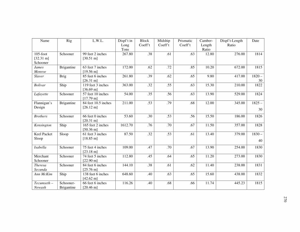
27
0
Name Rig L.W.L. Displ’t in
Long
Tons
Block
Coeff’t
Midship
Coeff’t
Prismatic
Coeff’t
Camber-
Length
Ratio
Displ’t-Length
Ratio
Date
105-foot
[32.31 m]
Schooner
Schooner 99 feet 2 inches
[30.51 m]
267.80 .38 .61 .63 12.80 276.00 1814
James
Monroe
Brigantine 63 feet 7 inches
[19.56 m]
172.00 .62 .72 .85 10.20 672.00 1815
Slaver Brig 85 feet 6 inches
[26.31 m]
261.80 .39 .62 .65 9.80 417.00 1820 –
30
Bolivar Ship 119 feet 3 inches
[36.69 m]
363.00 .32 .55 .63 15.30 210.00 1822
Lafayette Schooner 57 feet 10 inches
[17.79 m]
54.00 .35 .56 .63 13.90 529.00 1824
Flannigan’s
Design
Brigantine 84 feet 10.5 inches
[26.12 m]
211.00 .53 .79 .68 12.00 345.00 1825 –
30
Brothers Schooner 66 feet 0 inches
[20.31 m]
53.60 .30 .53 .56 15.50 186.00 1826
Kensington Ship 165 feet 2 inches
[50.36 m]
1612.70 .76 .70 .67 11.50 357.00 1828
Keel Packet
Sloop
Sloop 61 feet 3 inches
[18.85 m]
87.50 .32 .53 .61 13.40 379.00 1830 –
40
Isabella Schooner 75 feet 4 inches
[23.18 m]
109.00 .47 .70 .67 13.90 254.00 1830
Merchant
Schooner
Schooner 74 feet 5 inches
[22.90 m]
112.80 .45 .64 .65 11.20 273.00 1830
Theresa
Secunda
Schooner 84 feet 6 inches
[25.76 m]
144.10 .38 .61 .62 11.40 238.00 1831
Ann McKim Ship 138 feet 6 inches
[42.62 m]
648.60 .40 .63 .65 15.60 438.00 1832
Tecumseth –
Newash
Schooner-
Brigantine
66 feet 6 inches
[20.46 m]
116.26 .40 .68 .66 11.74 445.23 1815

271
APPENDIX E
“AN ACCOUNT OF RIGGING AND SAILS BELONGING TO HIS MAJESTY’S
SCHOONER NEWASH”
(Thomas Bushby, “An Account of Rigging and Sails Belonging to His Majesty’s
Schooner Newash,” LAC, Record Group 8, Series III, Volume 5.)
For What Use Species Quantity
Anchors Best Bower 8 cwt. 2 qrs. 0 lbs. [952 lbs or
432 kg]
One
Anchors Small Bower 7 cwt. 0 qrs. 0 lbs. [784 lbs or
356 kg]
One
[Cordage]
[For What Use] [Size] [Length]
Cablets 7 ½ inch [19.05 cm] Two
Cablets 4 inch [10.16 cm] One
Cablets 3 inch [7.62 cm] One
Bowsprit Shrouds 4 ½ inch [11.43 cm] Six fathoms
Bobstay 5 ½ inch [13.97 cm] Six fathoms
Jibboom Guys 2 ½ inch [6.35 cm] Twenty-four fathoms
Martingale Stays 2 ½ inch [6.35 cm] Thirty fathoms
Flying Jib Stay 3 inch [7.62 cm] Twenty-four fathoms
Jib Hallyards 2 inch [5.08 cm] Sixty-two fathoms
Jib Sheets 2 inch [5.08 cm] Eighteen fathoms
Jib Downhauller 1 ½ inch [3.81 cm] Twenty-two fathoms
Flying Jib Hallyards 2 inch [5.08 cm] Fifty fathoms
Flying Jib Sheets 2 inch [5.08 cm] Twenty-five fathoms
Flying Jib Downhauller 1 inch [2.54 cm] Forty fathoms
Horses for Jibboom 2 ½ inch [6.35 cm] Twelve fathoms
Fore Shrouds 5 inch [12.70 cm] Sixty fathoms
Fore Mast Head Pendants 5 inch [12.70 cm] Eight fathoms
Fore Runners 4 inch [10.16 cm] Twenty fathoms
Fore Tackles 2 inch [5.08 cm] Fifty fathoms
Fore Yard Lifts 2 inch [5.08 cm] Twenty-four fathoms
Fore Yard Trusses 1 ½ inch [3.81 cm] Eighteen fathoms
Fore Yard Horses 2 inch [5.08 cm] Nine fathoms
ForeYard Slings 6 inch [15.24 cm] Three fathoms
Fore [Gaff] Throat Hallyards 2 ½ inch [6.35 cm] Forty fathoms
Fore [Gaff] Peak Hallyards 2 ½ inch [6.35 cm] Thirty-six fathoms
Fore [Gaff] Vangs 2 ½ inch [6.35 cm] Ten fathoms
Fore [Gaff] Vang Falls 1 ½ inch [3.81 cm] Twenty fathoms
Fore Peak Brails 1 inch [2.54 cm] Thirty-six fathoms
Fore Throat Brails 1 ½ inch [3.81 cm] Thirty-eight fathoms
Fore Foot Brails 1 ½ inch [3.81 cm] Thirty-four fathoms

272
[For What Use] [Size] [Length]
Fore Sheets 2 ½ inch [6.35 cm] Thirty fathoms
Fore Topmast Shrouds 3 inch [7.62 cm] Twenty-two fathoms
Fore Topmast Stay 3 ½ inch [8.89 cm] Nineteen fathoms
Fore Topmast Backstays 3 inch [7.62 cm] Thirty-two fathoms
Fore Topsail Hallyards 2 inch [5.08 cm] Forty-two fathoms
Fore Topsail Sheets 2 ½ inch [6.35 cm] Forty-four fathoms
Fore Topsail Cluelines 1 ½ inch [3.81 cm] Forty fathoms
Fore Topsail Bowlines 1 ½ inch [3.81 cm] Fifty-four fathoms
Fore Topsail Horses 2 inch [5.08 cm] Six fathoms
Fore Topsail Lifts 2 ½ inch [6.35 cm] Twenty-eight fathoms
Fore Topsail Braces 2 ½ inch [6.35 cm] Ninety fathoms
Fore Topgallant Stay 2 inch [5.08 cm] Thirty-four fathoms
Fore Topgallant Hallyards 2 inch [5.08 cm] Thirty-six fathoms
Fore Topgallant Sheets 1 inch [2.54 cm] Twenty-five fathoms
Fore Topgallant Downhauller 1 inch [2.54 cm] Twenty fathoms
To Signal Hallyards ¾ inch [1.91 cm] Thirty-six fathoms
Square Sail Hallyards 2 inch [5.08 cm] Ninety fathoms
Square Sail Sheets 2 inch [5.08 cm] Twenty fathoms
Main Shrouds 5 inch [12.70 cm] Sixty fathoms
Main Mast Head Pendants 5 inch [12.70 cm] Sixty fathoms
Main Mast Head Stay 4 ½ inch [11.43 cm] Seven fathoms
Main Deck Stay 6 ½ inch [16.51 cm] Eleven fathoms
Main Deck Stay 5 inch [12.70 cm] Eleven fathoms
Main Runners 4 inch [10.16 cm] Twenty fathoms
Main Tackles 2 inch [5.08 cm] Fifty fathoms
Main Gaff Throat Hallyard 2 ½ inch [6.35 cm] Forty fathoms
Main Gaff Peak Hallyard 2 ½ inch [6.35 cm] Forty-two fathoms
Main Gaff Throat Downhaul 1 ½ inch [3.81 cm] Fourteen fathoms
Main Gaff Peak Downhaul 1 ½ inch [3.81 cm] Forty fathoms
Main Boom Sheet 2 ½ inch [6.35 cm] Twenty fathoms
Main Boom Topping Lift 4 inch [10.16 cm] Twenty-eight fathoms
Main Boom Topping Lift Falls 2 inch [5.08 cm] Sixty-four fathoms
Lazy Guy 4 inch [10.16 cm] Five fathoms
Tackle for Lazy Guy 2 inch [5.08 cm] Twelve fathoms
Main Reef Tackle 1 ½ inch [3.81 cm] Twenty-five fathoms
Main Reef Pendants 2 ½ inch [6.35 cm] Ten fathoms
Main Topmast Shrouds 3 inch [7.62 cm] Twenty fathoms
Main Topmast Stay 3 inch [7.62 cm] Ten fathoms
Main Topmast Backstays 3 inch [7.62 cm] Thirty-two fathoms
Signal Hallyards ¾ inch [1.91 cm] Forty fathoms
Gaff Topsail Hallyards 2 ½ inch [6.35 cm] Forty fathoms
Gaff Topsail Sheets 2 ½ inch [6.35 cm] Forty fathoms
Gaff Topsail Tacks 2 ½ inch [6.35 cm] Twenty-five fathoms
Gaff Topsail Downhauller 2 inch [5.08 cm] Thirty fathoms
Cat Falls 2 ½ inch [6.35 cm] Ten fathoms
Blocks
[For What Use] Quality Number
Cat Block Double 12 inch [30.48 cm] Two

273
[For What Use] [Quality] [Number]
Fore Top[sail] Bowline Single 6 inch [15.24 cm] Two
Flying Jib Downhauller and
Hallyard
Single 6 inch [15.24 cm] Two
Standing Jib Downhauller and
Hallyard
Single 6 inch [15.24 cm] Three
Standing Jib Sheets Single 8 inch [20.36 cm] Two
Flying Jib Stay Single 6 inch [15.24 cm] Five
Fore Brace Single 6 inch [15.24 cm] Two
Fore Lift Single 6 inch [15.24 cm] Two
Fore Topsail Sheet Single 9 inch [22.86 cm] Two
Fore Topsail Hallyard Single 6 inch [15.24 cm] Three
Fore Lift Double 8 inch [20.36 cm] Two
Peak Hallyards Double 9 inch [22.86 cm] One
Peak Hallyards Single 9 inch [22.86 cm] One
Throat Hallyards Double 9 inch [22.86 cm] One
Throat Hallyards Single 9 inch [22.86 cm] One
Topsail Hallyard and Clueline Double 6 inch [15.24 cm] Three
Square Sail Hallyard Single 6 inch [15.24 cm] One
Fore Runner and Tackle Single 9 inch [22.86 cm] Four
Fore Runner and Tackle Double 9 inch [22.86 cm] Two
Brail Blocks Single 6 inch [15.24 cm] Eight
Brail Blocks Double 6 inch [15.24 cm] One
Fore Sheet Single 9 inch [22.86 cm] Two
Fore Vangs Single 6 inch [15.24 cm] Four
Main Stay Double 9 inch [22.86 cm] Four
Main Runners and Tackles Single 9 inch [22.86 cm] Four
Main Runners and Tackles Double 9 inch [22.86 cm] Two
Boom Topping Lift Single 10 inch [25.40 cm] Two
Boom Topping Lift Falls Double 8 inch [20.36 cm] Two
Boom Topping Lift Falls Single 8 inch [20.36 cm] Two
Throat Hallyard Double 8 inch [20.36 cm] One
Throat Hallyard Single 8 inch [20.36 cm] One
Peak Hallyard Double 8 inch [20.36 cm] One
Peak Hallyard Single 8 inch [20.36 cm] One
Throat Downhaul Single 6 inch [15.24 cm] One
Peak Downhaul Double 6 inch [15.24 cm] One
Boom Sheets Double 9 inch [22.86 cm] Two
Lazy Guy Double 8 inch [20.36 cm] One
Lazy Guy Single 8 inch [20.36 cm] One
Reef Tackle Fall Double 6 inch [15.24 cm] One
Reef Tackle Fall Single 6 inch [15.24 cm] One
Gaff Topsail Hallyard Single 8 inch [20.36 cm] One
Gaff Topsail Sheet Single 8 inch [20.36 cm] Two
Gaff Topsail Downhauller Single 6 inch [15.24 cm] One
Sails
Flying Jib One
Standing Jib One
Gaff Foresail One

274
[Sails]
Square Sail One
Fore Topsail One
Fore Topgallantsail One
Boom Mainsail One
Main Topsail One – To be converted into a
Main Topgallantsail One – Gaff Topsail
Wanting to Complete for Six Months
Quality Species Quantity
Rope 4 ½ inch [11.43 cm] Thirty fathoms
Rope 3 ½ inch [8.89 cm] One Coil
Rope 3 inch [7.62 cm] One Coil
Rope 2 ½ inch [6.35 cm] Three Coils
Rope 2 inch [5.08 cm] Two Coils
Rope 1 ½ inch [3.81 cm] Two Coils
Rope 1 inch [2.54 cm] Two Coils
Rope ¾ inch [1.91 cm] One Coil
Tallow Fifty-six lbs.
Junk Five cwt.
Lead Lines Deepsea One
Hand Lines Four
Log Lines Eight
Canvas No. 5 One Bolt
Canvas No. 6 One Bolt
Canvas No. 7 One Bolt
Canvas No. 8 One Bolt
Twine and Needles in
Proportion
Glass ½ hour One
Glass ½ minute One
Glass ¼ minute One
Hooks Boat Five
Paint White Thirty lbs.
Paint Black Thirty lbs.
Paint Yellow Ten lbs.
Oil Lynseed Twelve Gallons
Oil Dryar Two lbs.
Spirits Turpentine Four Gallons
Varnish Black Ten Gallons
Thimbles of Sizes Fifty
Tackle Hooks Thirty
Blocks Double 5 inch [12.70 cm] Two
Blocks Double 6 inch [15.24 cm] Twelve
Blocks Double 7 inch [17.78 cm] Six
Blocks Double 8 inch [20.36 cm] Ten
Blocks Double 9 inch [22.86 cm] Six
Blocks Double 10 inch [25.40 cm] Two
Blocks Cat Double 12 inch [30.48 cm] Two
Blocks Single 6 inch [15.24 cm] Twenty

275
[Quality] [Species] [Quantity]
Blocks Single 7 inch [17.78 cm] Twelve
Blocks Single 8 inch [20.36 cm] Ten
Blocks Single 9 inch [22.86 cm] Six
Blocks Single 10 inch [25.40 cm] Four
Blocks Single 11 inch [27.94 cm] Six
Old Canvas Fifty yards
Hammocks Twenty-five

276
APPENDIX F
SPAR LENGTH PROPORTIONS FROM HOWARD I. CHAPELLE’S THE
BALTIMORE CLIPPER, PAGE 160.
Main mast, hounded Extreme Breadth x 2.60 – 2.80
Fore Mast, hounded Main Mast x 0.90 – 0.97
Topmasts, hounded Extreme Breadth x 0.83 – 1.00
Heads of Lower Masts Topmasts x 0.30 – 0.40
Pole heads of Topmasts Hounded length x 0.50
Bowsprit LWL x ~0.33
Jibboom LWL x ~0.40
Main Boom LWL x 0.66 – 0.75
Main Gaff Main Boom x 0.48 – 0.53
Fore Gaff Main Gaff x 0.73 – 1.00
Fore Yard LWL x 0.48 – 0.57
Fore Topsail Yard Fore Yard x 0.70 – 0.75
Fore Topgallant Yard Fore Yard x 0.42 – 0.48
Main Yards nearly equal to fore stack
Square Sail Boom LWL x 0.37 – 0.44
277
APPENDIX G
E-MAIL COMMUNICATION FROM CAPTAIN WALTER RYBKA ON THE USE OF
HEARTS AND DEADEYES
Hello to both LeeAnne and Kevin,
I have never found a definitive answer as to why hearts are used on stays and deadeyes
on shrouds. However, based on operational experience I can offer a supposition:
In tuning the rig it is more of a challenge to get the stays tight enough, and to keep them
that way. You only have one or two stays leading forward per mast section, but four to
seven shrouds. Furthermore, the greatest strain on the rig probably came when staying
(tacking) into a head sea. Slack stays would not only allow the headsails to sag off to
leeward (destroying windward ability) but would also permit the masts to whip fore and
aft from the pounding of a sea on the bow, as well as from the sudden shift of square sails
full to aback during maneuvers. So keeping the stays taut was more important than the
shrouds.
Deadeyes to my knowledge never had more than three holes, and rove off from one side
to the other. This limited them to six parts of line, which was the most practical due to
cumulative friction when hauling on only one end of the lanyard. In fact the hard part of
setting up deadeyes is not having one of them rotate due to the assymetrical [sic] strain.
The deadeye needs to be tightly seized into the shroud, and the lanyard needs to be well
lubricated and attention payed [sic] to all parts moving as the lanyard is rove taut. A
deadeye is inherently stronger than a heart, offering so much more wood to rope ratio, but
the cost is in the friction of that much bearing surface.
Hearts were typically scored for four to even five parts. Smaller ones had one end of the
lanyard spliced and hauled on the other, and were really no better than a deadeye. But it
was also possible to middle the lanyard, pass it over a center score in one heart, and then
278
reeve each end in opposite directions. The result would be two hauling parts on the one
lanyard which could be hove taut either together or separately. By dividing the pull this
way you could have more parts rove, but less cumulative friction than would occur with
one bitter end secured.
So to sum up, I think hearts were used where there was room for a bulkier arrangement
combined with the need for more tension than could be achieved with a deadeye.
What I have never figured out is why the idea of a double ended lanyard wasn’t applied
to deadeyes. If you used a three hole deadeye for the upper, and a four hole for the lower,
and began reeving from the center hole of the upper, each end going in opposite
directions through the center holes of the lower, you would end up with eight parts of line
instead of six, but no one part had to move through more than three holes. There has to
be a catch, the idea must have been tried and discarded. Or perhaps several centuries too
late I have stumbled onto an improved version of a stone ax.
Best wishes, Walter

279
VITA
LeeAnne Elizabeth Gordon received a Bachelor of Arts degree in English from Auburn
University in 2001. After graduation, Miss Gordon spent several years sailing in
traditionally-rigged tall ships. In her travels, she has sailed on all five Great Lakes as
well as the east and west coasts of the United States and Canada and the Caribbean. She
entered the Nautical Archaeology Program in the Anthropology Department at Texas
A&M University in August 2006 and received her Master of Arts degree in May 2009.
Miss Gordon’s research interests include the Great Lakes, the War of 1812 and sail
training.
Miss Gordon can be reached at 1665 Davison Road, Harborcreek, PA 16421. Her e-mail
address is [email protected].


