

Next Generation TV: ATSC 3.0
HOW DOES IT WORK?
OCT 1, 2018
Rich ChernockATSC TG Chair Emeritus

IEEE Broadcast Technology Society
IEEE BROADCAST TECHNOLOGY SOCIETY
“ THE TECHNOLOGIES TO DELIVER INFORMATION AND ENTERTAINMENT TO AUDIENCES WORLDWIDE, AT HOME AND ON THE GO.”
Benefits of IEEE BTS Membership
The BTS is a trans-national Society with over 2000 members and 20 Chapters worldwide. Our Society concerns itself with devices, equipment, techniques and systems related to broadcast technology, including the production, distribution, transmission, and propagation aspects. Our Society is working to advance the professional standing and education of its Members, through our publications, conferences, tutorials and Chapter meetings.
10/1/20184
Distinguished Lecturer ProgramMission: To serve the needs of the members of the Broadcast Technology Society to enhance their professional knowledge and vitality by keeping them informed of the latest research results and their practical applications. The BTS Distinguished Lecturer Program exists for the purpose of providing BTS chapters with a list of quality lecturers who can potentially give talks at local chapter meetings, as well as funding to support the travel expenses of the lecturer. The program provides a means for chapters to have access to individuals who are well known educators and authors in the fields of broadcast technology to lecture at chapter meetings.
10/1/20185

6
• USA
• UK
• Canada
• France
• Italy
• Singapore
• Argentina
• China
• Spain
• Korea
• Malaysia
• DTV & MPEG
• ATSC 3.0
• Display Monitors
• Cameras
• Satellite
• Audio Loudness
• Video & Audio Compression & Coding technologies
• Channel Rate allocation techniques
• 3D TV
• Digital Radio
• Broadcast Regulatory & Legislative Issues
• 8-VSB
• AM, FM, TV antennas
• Image Artifacts
• Directional Pattern design for antennas
• Multimedia Broadcast Services w/ Distributed Transmission Network
• Signal Processing in Broadband Multimedia Communications
• Transmitter ID for Digital Video Broadcast
• SFN, Distributed & Cloud Transmission Systems
• Wind Turbine impact to UHF Band DTV
• Video Streaming w/Multiple Description Coding & Network Diversity
• Temporal Dependant Rate Distortion Optimization in Motion Compensated Video Coding

Please Consider Joining IEEE Broadcast Technology SocietyTODAY
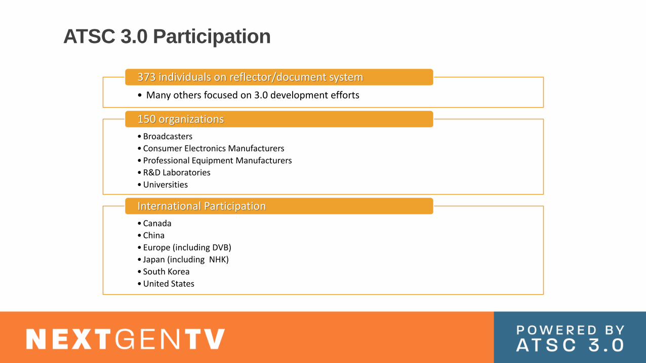
ATSC 3.0 Participation
• Many others focused on 3.0 development efforts
373 individuals on reflector/document system
• Broadcasters
• Consumer Electronics Manufacturers
• Professional Equipment Manufacturers
• R&D Laboratories
• Universities
150 organizations
• Canada
• China
• Europe (including DVB)
• Japan (including NHK)
• South Korea
• United States
International Participation

Goals of ATSC 3.0
To add value to the
broadcasting service platform
Enables new business models
Reaches more viewers on more
devices
To address changing consumer behavior
Provides higher quality audio
and video, more accessibility
Watch what you want, when you want, where you
want
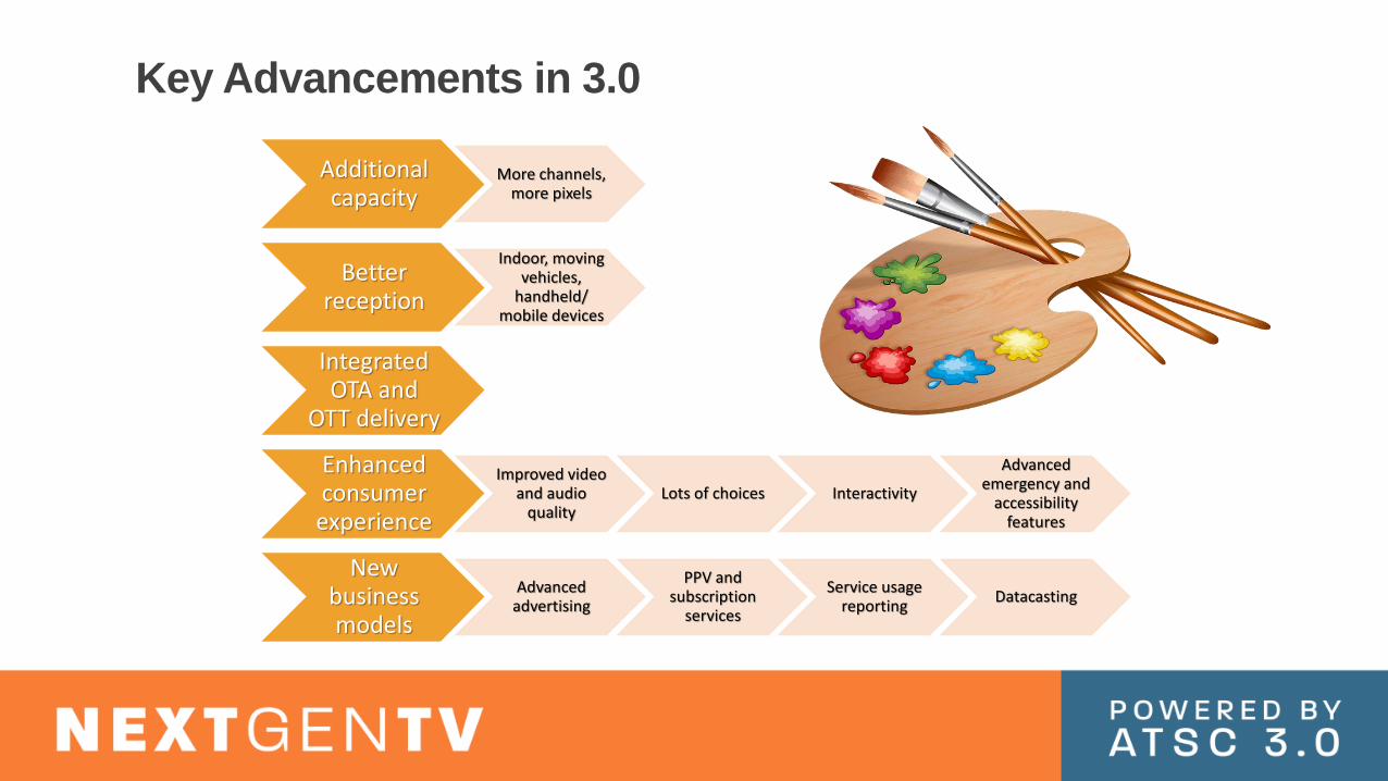
Key Advancements in 3.0
Additional capacity
More channels, more pixels
Better reception
Indoor, moving vehicles,
handheld/mobile devices
Integrated OTA and
OTT delivery
Enhanced consumer experience
Improved video and audio
qualityLots of choices Interactivity
Advanced emergency and
accessibility features
New business models
Advanced advertising
PPV and subscription
services
Service usage reporting
Datacasting

ATSC 3.0 Physical Layer and Transport Layer

Physical Layer Architecture
Input Formatting
Enca
psu
lati
on
Sch
edu
ling
Bas
eban
d
Pack
etiz
ing
Scra
mb
ling
Bit Interleaving, Coding And Modulation (BICM)
Forw
ard
Err
or
Co
rrec
tio
n (
FEC
)
Bit
Inte
rlea
vin
g
Mo
du
lati
on
M
app
ing
Framing and Interleaving
Tim
e In
terl
eavi
ng
Fram
ing
/ C
ell
Mu
ltip
lexi
ng
Freq
uen
cy
Inte
rlea
vin
g
Waveform Generation
Pilo
t In
sert
ion
Inve
rse
Fast
Fo
uri
er T
ran
s.
Peak
to
Ave
rage
Po
wer
Red
uct
ion
Gu
ard
Inte
rval
Ad
d B
oo
tstr
ap

0
2
4
6
8
10
12
-10 -5 0 5 10 15 20 25 30 35
BIC
M L
ink
Eff
icie
nc
y
(bit
s/s
/Hz)
SNR (dB)
Bit Interleaving, Coding, and Modulation Performance
Shannon Limit
ATSC 3.0, QPSK
ATSC 3.0, 16QAM
ATSC 3.0, 64QAM
ATSC 3.0, 256QAM
ATSC 3.0, 1024QAM
ATSC 3.0, 4096QAM
ATSC 1.0
A/53
Low Capacity, More Robust
High Capacity, Less Robust

Frame Hierarchy for Payload
• The largest physical layer container for carrying data traffic is a physical layer frame
Frames
• Each frame contains one or more subframes
• Each subframe is associated with a subframe type, which is a function of the OFDM configuration parameters for that subframe
• Subframes within the same frame can have the same or different type
Subframes
• Each subframe contains one or more physical layer pipes which carry actual payload data
• A PLP’s throughput capacity depends on: Forward Error Correction (FEC) code rate, modulation order, and number of allocated cells
• Multiple PLPs for different services can share the same subframe
• Maximum of 64 distinct PLPs in an RF channel; maximum of 4 PLPs in a given service
Physical Layer Pipes (PLPs)

Signaling HierarchyA frame consists of bootstrap, preamble, and data portions
L1-B
asic
Sig
nal
ing
L1-D
eta
il S
ign
alin
g
Su
b-F
ram
e P
aylo
ad
Su
b-F
ram
e P
aylo
ad
Su
b-F
ram
e P
aylo
ad
… …
Bootstrap Signal
Preamble Frame
Time
Fre
qu
en
cy
o The bootstrap serves as the robust universal entry point to a waveform and signals parameters that enable decoding of L1-Basic
o L1-Basic signals parameters that enable the decoding of L1-Detail and the initial processing of the first subframe.

Layer Division Multiplexing (LDM)
Layer Division Multiplexing (LDM) is based upon the superposition of
two signals operating at
different amplitude (power) levels.
LDM Capable Receiver is able to “subtract” the core layer to decode the
enhanced layer
LDM provides large “gain” in
transmission efficiency
Time Division Multiplexing
(TDM), Frequency Division
Multiplexing (FDM) along with LDM are
all possibleLDM overlay spectrum
RFChannel BW
5 dB
Core Layer
6 dB
Enhanced Layer
Future Extension Layer
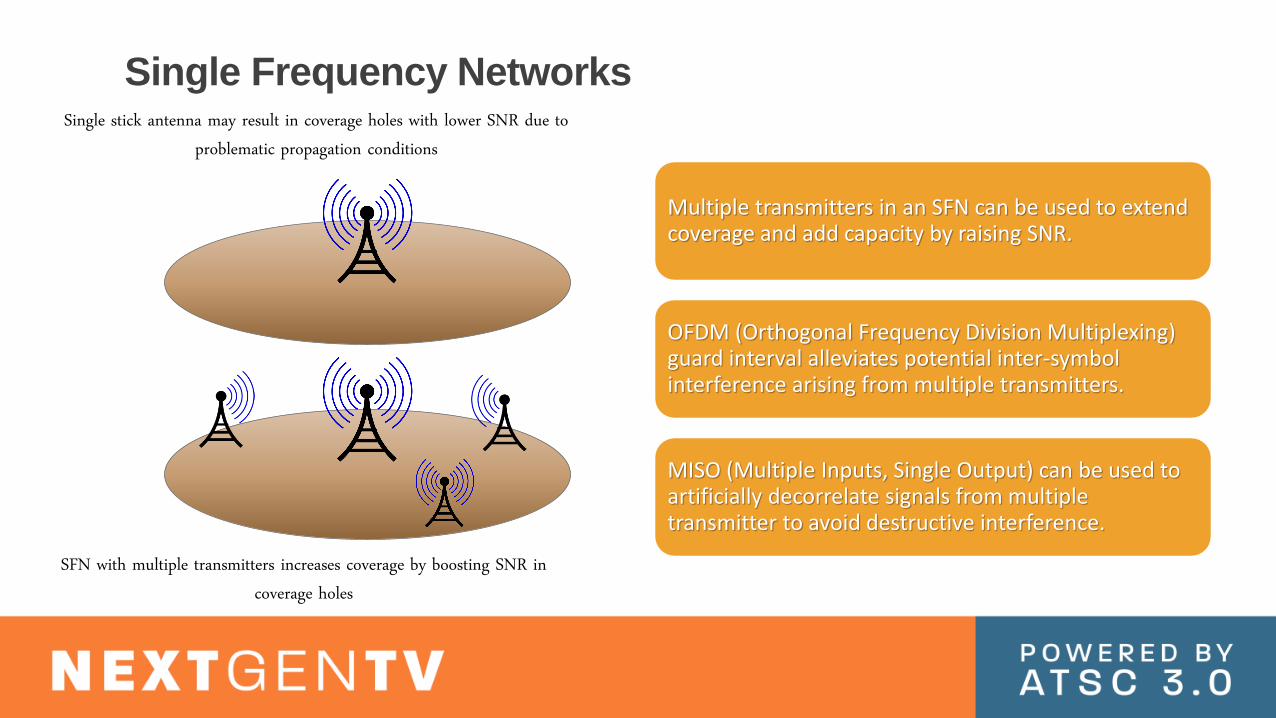
Single Frequency Networks
Multiple transmitters in an SFN can be used to extend coverage and add capacity by raising SNR.
OFDM (Orthogonal Frequency Division Multiplexing) guard interval alleviates potential inter-symbol interference arising from multiple transmitters.
MISO (Multiple Inputs, Single Output) can be used to artificially decorrelate signals from multiple transmitter to avoid destructive interference.
Single stick antenna may result in coverage holes with lower SNR due to problematic propagation conditions
SFN with multiple transmitters increases coverage by boosting SNR in coverage holes

Single Frequency Network (1)
Radio Horizon Spillover into adjacent market
This set-up can be used to enable continuous service from one DMA to another

Single Frequency Network (2)
Radio Horizon
> Indoor Reception
This set-up can be used to increase coverage in a given DMA
No spill-over into adjacent market

Washington, DC without SFN (example)
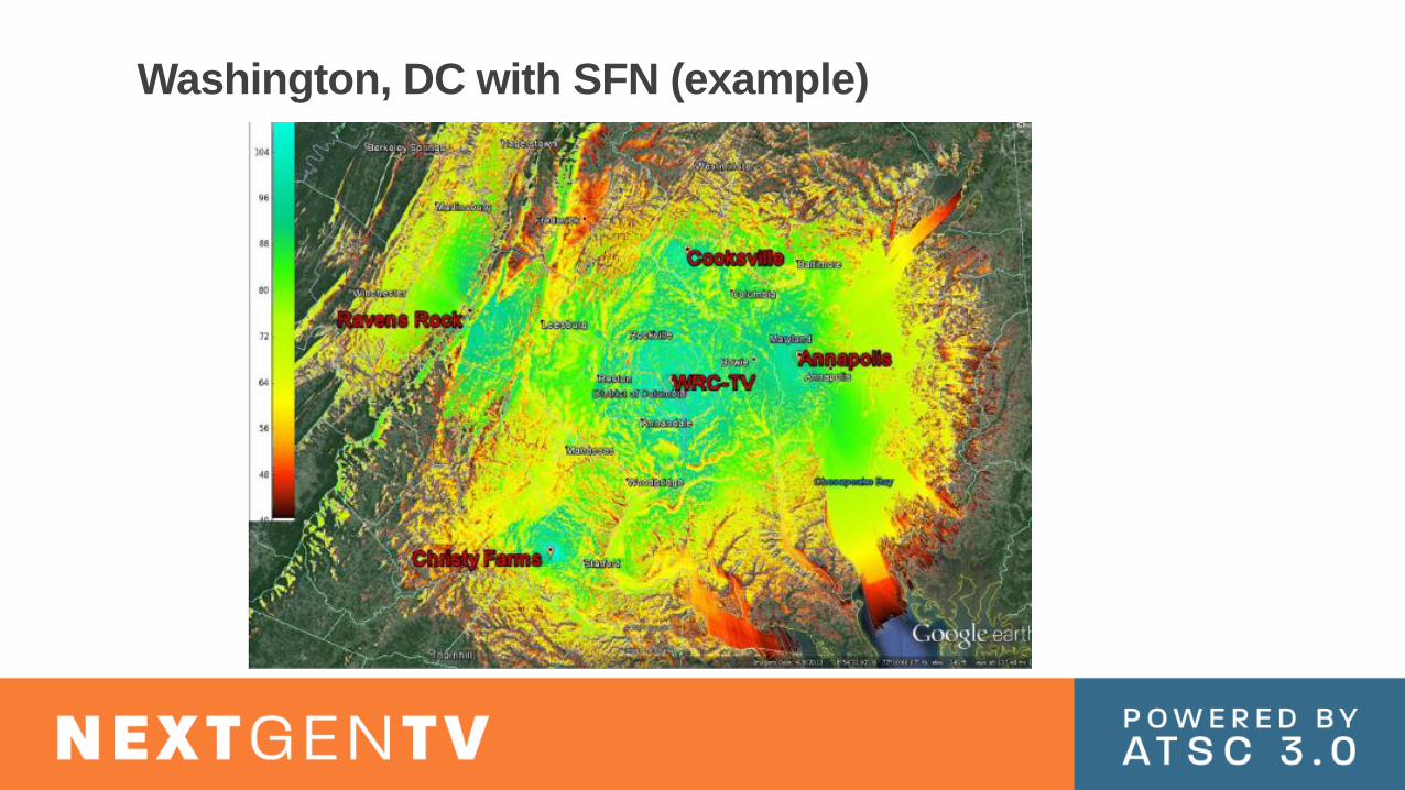
Washington, DC with SFN (example)

Physical Layer Benefits
The ATSC 3.0 suite of standards
enables many system options for the broadcasting
industry
Hierarchical control signaling
of parameters provides robust
yet efficient communication of
waveform configuration
High robustness, spectrally efficient operating points
Flexible configuration of operating modes
with large SNR range
Very robust synchronization with signaling of
basic system parameters to
allow for future technology advances
Many flexible functions
(framing, time interleaving, etc.) for optimization per broadcaster
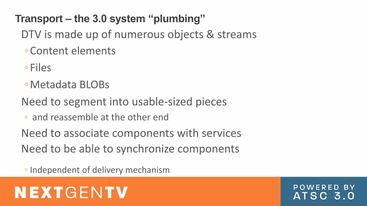
Transport – the 3.0 system “plumbing”
DTV is made up of numerous objects & streams
◦Content elements
◦Files
◦Metadata BLOBs
Need to segment into usable-sized pieces◦ and reassemble at the other end
Need to associate components with services
Need to be able to synchronize components
◦ Independent of delivery mechanism

Transport Layer Key Elements
Common elements include◦ Use of IP Transport for broadcast delivery◦ Use of ISOBMFF as a content format
for streaming delivery
◦ Use of UTC for synchronization and buffer management◦ All elements of the system
“know what time it is”
IP-based protocols
ISOBMFF streaming
media format
UTC clock reference
moovftyp moof mdatmoof mdatmoof
moovftyp moof moof moofstyp styp
ISOBMFF file
Initialization Segment Media Segment Media Segment
mdat
mdat mdatmdat
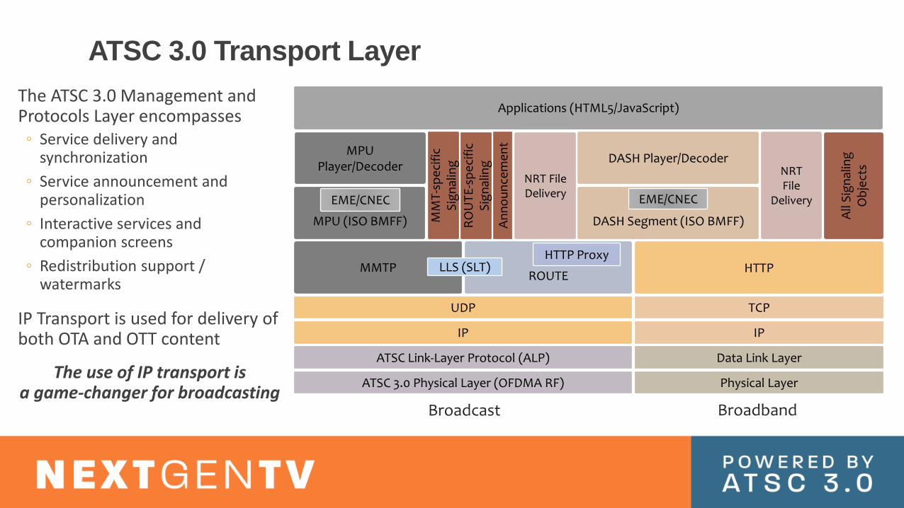
ATSC 3.0 Transport Layer
Broadcast Broadband
Physical Layer
ATSC Link-Layer Protocol (ALP) Data Link Layer
IP IP
UDP TCP
MMTPROUTE
HTTP ProxyHTTP
MM
T-s
pe
cifi
c S
ign
alin
g
RO
UT
E-s
pe
cifi
c S
ign
alin
g
MPU (ISO BMFF)
NRT File Delivery
DASH Segment (ISO BMFF)
NRT File
Delivery
All
Sig
nal
ing
O
bje
cts
DASH Player/DecoderMPU
Player/Decoder
LLS (SLT)
EME/CNEC EME/CNEC
An
no
un
cem
en
t
Applications (HTML5/JavaScript)
ATSC 3.0 Physical Layer (OFDMA RF)
The ATSC 3.0 Management and Protocols Layer encompasses
◦ Service delivery and synchronization
◦ Service announcement and personalization
◦ Interactive services and companion screens
◦ Redistribution support / watermarks
IP Transport is used for delivery of both OTA and OTT content
The use of IP transport is a game-changer for broadcasting

Transport – the 3.0 system “plumbing” (comparison)
DTV is made up of numerous objects & streams No change
◦Content elements
◦Files
◦Metadata BLOBs
Need to segment into usable-sized pieces IP Packets vs MPEG-2 TS packets
◦ and reassemble at the other end
Need to associate components with services IP Address/Port vs PIDs
Need to be able to synchronize components Universal System time vs STC established via PCRs
◦ Independent of delivery mechanism
ATSC 3.0 Video System

ATSC 3.0 Video Resolutions up to 3840 × 2160
Spatial scalability (SHVC)
• Up to 100, 120, 120/1.001 (plus lower framerates)
• Temporal sub-layering enables backward compatibility
• Plus temporal filtering for optimizing both the SFR and HFR pictures
High Frame Rate
• PQ & HLG transfer functions (plus SDR)
• Metadata for PQ
High Dynamic Range
• Wide Color Gamut BT.2100 (plus BT.709 for SDR)
• Y’CBCR non-constant luminance
• ICTCP constant luminance (for PQ)
• Full Range coding (for PQ)
• SL-HDR1 for delivering SDR/709 stream that SL-HDR1-capable decoders can render as HDR/2020
Wide Color Gamut

• SD: {640,704,720}x480
• HD: {1440,1920}x1080
Legacy Interlace
Video Formats
• Resolutions: 16:9/square pixels, divisible by 8 in both dimensions, up to 3840x2160
• HDR, WCG, HFR, 4K, Scalable, etc. are only supported for progressive formats
Progressive Video Formats
Legacy and Progressive Video Formats
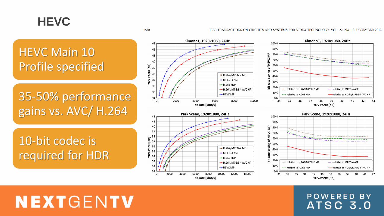
HEVC Main 10 Profile specified
35-50% performance gains vs. AVC/ H.264
10-bit codec is required for HDR
HEVC

Limited to 2 spatial layers
Base layer optimized for mobile reception
Enhancement layer optimized for UHD resolution
SHVC: Spatial Scalability
SHVC encoder
BL encoder(HD)
EL encoder(UHD)
UHD
source
2x down-scaling
ATSC
3.0
PHY
layerUHD
videoHigh BW
High
robust-
ness
HD, audio
HEVC decoder
SHVC decoder
UHD
video
HD
video
Mobile / distant receiver
Fixed receiver
High loss
channel
Low loss
channel
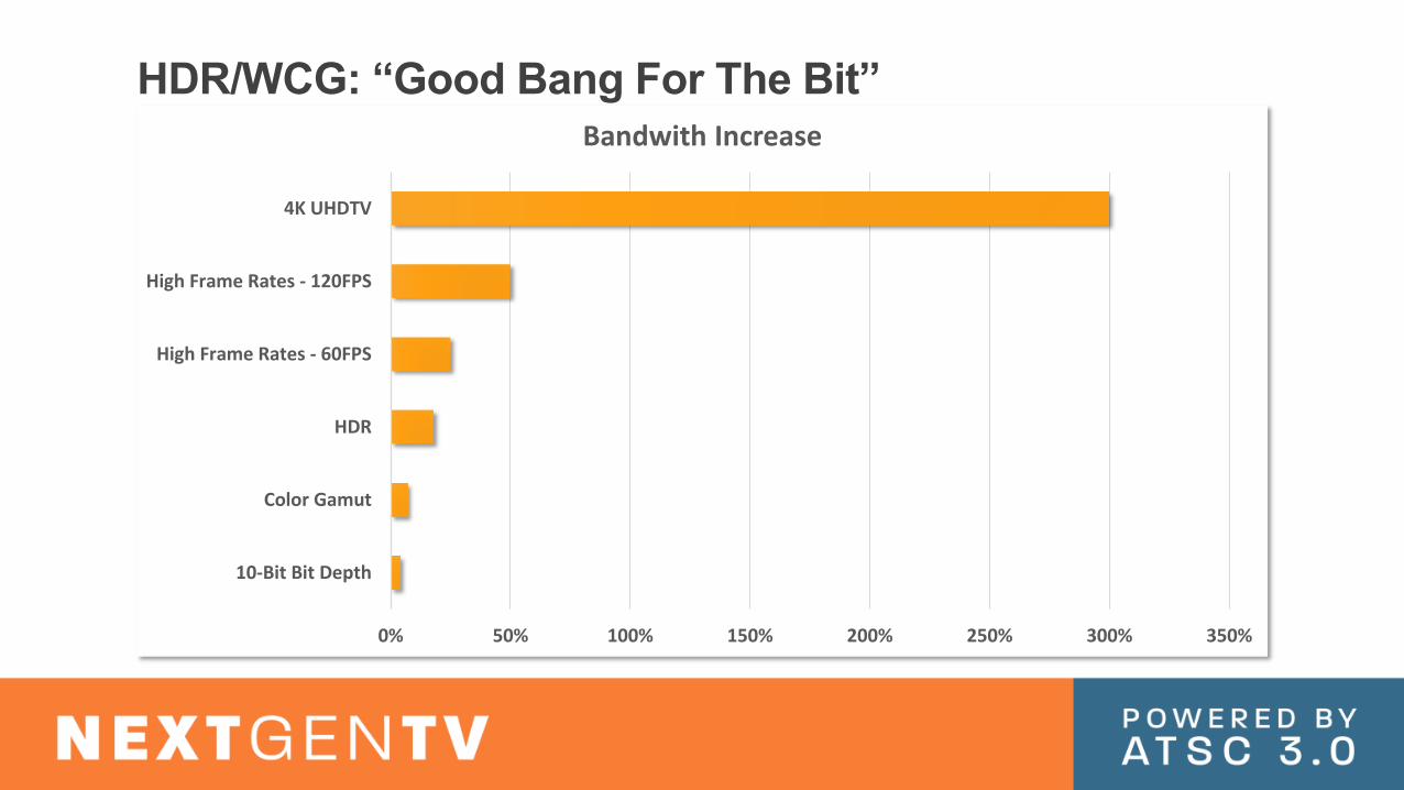
HDR/WCG: “Good Bang For The Bit”
0% 50% 100% 150% 200% 250% 300% 350%
10-Bit Bit Depth
Color Gamut
HDR
High Frame Rates - 60FPS
High Frame Rates - 120FPS
4K UHDTV
Bandwith Increase
ATSC 3.0 Audio System

2 audio technologies are standardized in the ATSC 3.0 suite
• Dolby AC-4 for use in the U.S.
• MPEG-H in South Korea1 technology per country or region
ATSC 3.0 Audio Systems
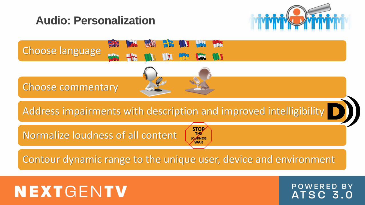
Choose language
Choose commentary
Address impairments with description and improved intelligibility
Normalize loudness of all content
Contour dynamic range to the unique user, device and environment
Audio: Personalization
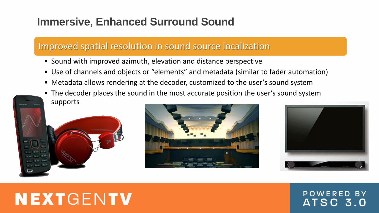
Immersive, Enhanced Surround Sound
Improved spatial resolution in sound source localization
• Sound with improved azimuth, elevation and distance perspective
• Use of channels and objects or “elements” and metadata (similar to fader automation)
• Metadata allows rendering at the decoder, customized to the user’s sound system
• The decoder places the sound in the most accurate position the user’s sound system supports

Headphone Reproduction Will Simulate Height & Depth –
Sounding more like speakers and the feeling of listening in a room
Rendering for Headphones
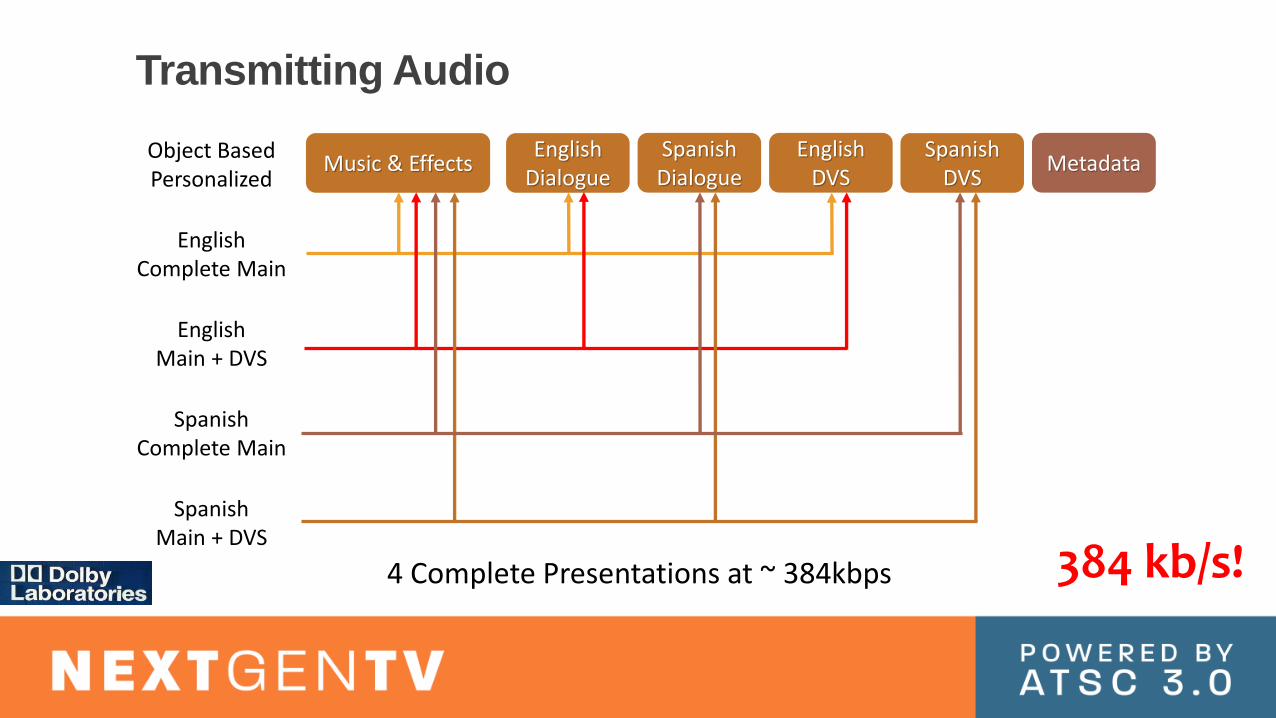
Transmitting Audio
4 Complete Presentations at ~ 384kbps
Music & EffectsEnglish
DialogueSpanishDialogue
EnglishDVS
SpanishDVS
MetadataObject BasedPersonalized
EnglishComplete Main
EnglishMain + DVS
SpanishComplete Main
SpanishMain + DVS
4 Complete Presentations at ~ 384kbps 384 kb/s!
ATSC 3.0 Accessibility
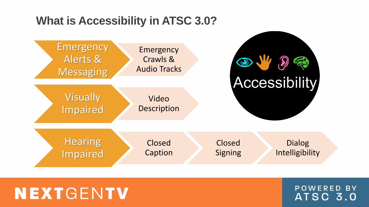
What is Accessibility in ATSC 3.0?
Emergency Alerts &
Messaging
Emergency Crawls &
Audio Tracks
Visually Impaired
Video Description
Hearing Impaired
Closed Caption
Closed Signing
Dialog Intelligibility

ATSC 1.0 requires VD to be sent as a secondary audio program typically mono or stereo mix down with narration.
ATSC 3.0 allows VD object element to be broadcast in audio stream and mixed in with music, dialog and effects with minimal effect on broadcast capacity while providing a better experience to audience.
Aural renderings of emergency messages can also be an object element
In both cases multiple versions are possible (e.g., alternate languages)
Visually Impaired

• Mandatory
• IMSC1 via broadcast
• Optional
• IMCS1 via broadband (e.g. alt. language)
• 608/708 in the video SEI
Caption Stream
• In ATSC 1.0 the mix cannot be easily modified.
• In ATSC 3.0 the dialog can be maintained as a separate element.
Dialog Intelligibility
• Interactive standard enables Picture in Picture
• PiP can be used for sign language that can be toggled on/off like captions
Closed Signing
Hearing Impaired
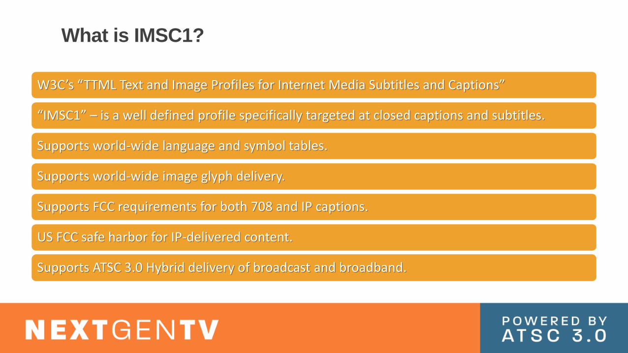
W3C’s “TTML Text and Image Profiles for Internet Media Subtitles and Captions”
“IMSC1” – is a well defined profile specifically targeted at closed captions and subtitles.
Supports world-wide language and symbol tables.
Supports world-wide image glyph delivery.
Supports FCC requirements for both 708 and IP captions.
US FCC safe harbor for IP-delivered content.
Supports ATSC 3.0 Hybrid delivery of broadcast and broadband.
What is IMSC1?

ATSC 3.0 Interactivity
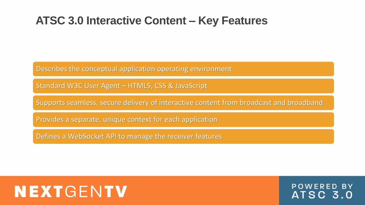
ATSC 3.0 Interactive Content – Key Features
Describes the conceptual application operating environment
Standard W3C User Agent – HTML5, CSS & JavaScript
Supports seamless, secure delivery of interactive content from broadcast and broadband
Provides a separate, unique context for each application
Defines a WebSocket API to manage the receiver features

Foundation 1: HTML5
• Current Web Standard
HTML5: HyperText Mark-up Language, version 5
• Refers to other pages and content using URLs
• <a href=“http://www.xbc.com/somepage.html”>My Web Site</a>
Simple Language: Elements (tags), Attributes, and Text
• <a href=“http://www.xbc.com/somepage.html”><img class=“someClass” source=“images/myicon.png” title=“A ToolTip” border=“0”width=“16px” height=“16px” />
</a>
Elements can be nested
• Loaded pages are represented in a Document Object Model (DOM)
• The DOM provides data and built-in APIs for JavaScript manipulation
HTML5 Pages are loaded into User Agents (e.g. Browsers)
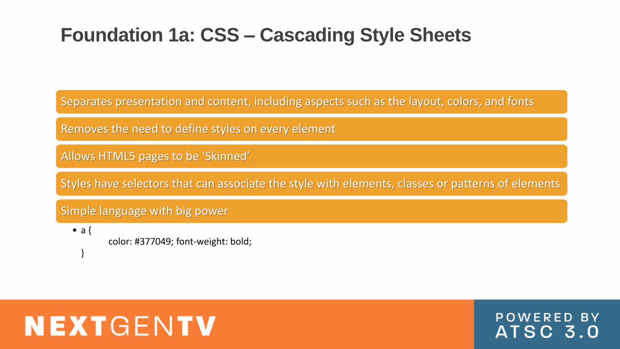
Foundation 1a: CSS – Cascading Style Sheets
Separates presentation and content, including aspects such as the layout, colors, and fonts
Removes the need to define styles on every element
Allows HTML5 pages to be ‘Skinned’
Styles have selectors that can associate the style with elements, classes or patterns of elements
Simple language with big power
• a {color: #377049; font-weight: bold;
}

Foundation 2: JavaScript
High-level, dynamic, untyped, and interpreted run-time language
• Standardized in the ECMAScript language specification
The Language of the Broadcaster Application
• HTML5 & CSS describe data
• JavaScript codifies logic that manipulates that data
<button id="hellobutton">Hello</button>
<script>
document.getElementById( 'hellobutton‘ ).onclick = function() {
alert('Hello world!'); // Show a dialog
var myTextNode = document.createTextNode('Some new words.');
document.body.appendChild(myTextNode); // Append "Some new words" to the page
};
</script>

Interactivity – Example
When a goal is scored, an event can be sent to the app causing celebration graphics to appear.
ADVANCED EMERGENCY ALERTS

What is Advanced Emergency Alerting?
Enables broadcasters to deliver a rich set of data and media to viewers or non-public audiences
• Text, images, video, interactive interfaces
• Viewer can dismiss messages (unlike “burned-in” crawls)
Supplements, enhances, but doesn’t replace EAS
Possibility of geo-targeting
• For receivers that “know where they are”
Possibility of waking up devices in stand-by mode
Possibility of targeting (and encrypting) messaging for groups (first responders, gov’t, business…)

AEA Wake-up Function
The Bootstrap is the initial discovery and entry point in the ATSC 3.0 waveform
Wake-up Field is comprised of two bits in
the Bootstrap
Two bits = 4 wakeup states…one negative and 3 positive
• Change in state is what matters
• Designed to avoid nuisance factor and extend battery life
Note that there is one Bootstrap per RF band
• Broadcasters that are channel-sharing must coordinate use of the wake-up bits
Bo
ots
tra
p
Pre
am
ble
Time
Fre
qu
en
cy
Frame
Subframe 0 Subframe n-1. . .

Advanced Emergency Alert Table AEAT contains the
elements and attributes of the emergency messages
Who gets it
When
Where
Alert Narrative
File-basedMedia
Live Media
Alert Summary

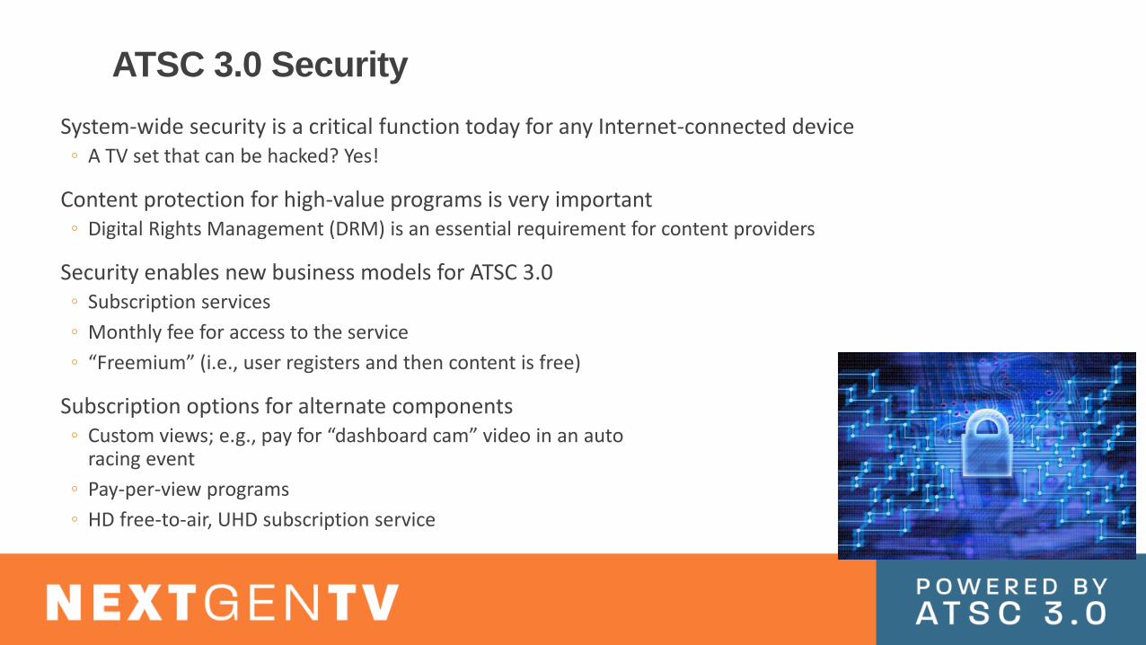
ATSC 3.0 Security
System-wide security is a critical function today for any Internet-connected device◦ A TV set that can be hacked? Yes!
Content protection for high-value programs is very important◦ Digital Rights Management (DRM) is an essential requirement for content providers
Security enables new business models for ATSC 3.0◦ Subscription services
◦ Monthly fee for access to the service
◦ “Freemium” (i.e., user registers and then content is free)
Subscription options for alternate components◦ Custom views; e.g., pay for “dashboard cam” video in an auto
racing event
◦ Pay-per-view programs
◦ HD free-to-air, UHD subscription service

Security ResultsContent Encryption (CA and/or DRM)◦ Allows charging for premium content
◦ Allows use of “Freemium” model◦ For example, agreement to allow anonymous usage monitoring in return for access to extra/premium content
◦ Allows protection of content once it arrives on receiving device
Allows transactions over the Internet◦ Return channel has same concerns as general Internet use, but same technology solutions
can be used
Provides protections against MITM attacks◦ Application & Signaling Signing
◦ Use of DRM on content & signed signaling

ATSC 3.0 is a Powerful New Tool
New business opportunities
Flexible physical layer supports wide range of service types
Great improvements in pictures and sound
New interactivity features
Advanced emergency messaging tools
New accessibility enhancements
More robust signal and higher data capacity
And, and, and….

ATSC 3.0 Standards
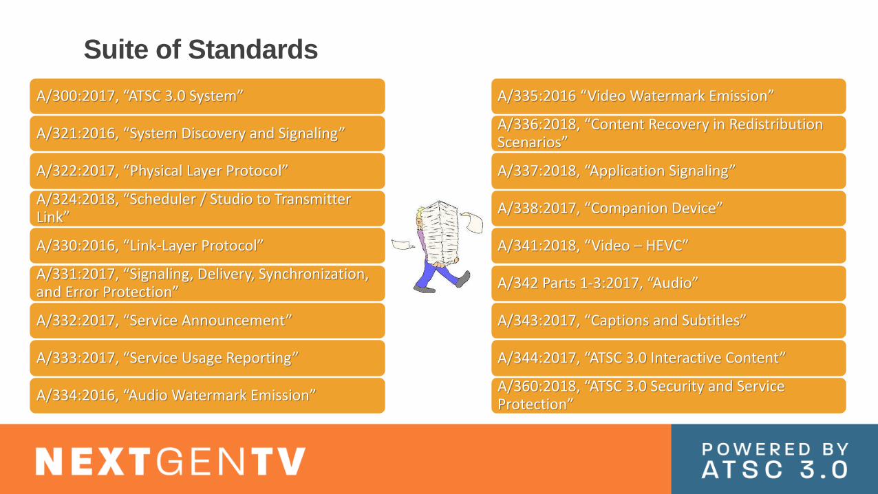
Suite of Standards
A/300:2017, “ATSC 3.0 System”
A/321:2016, “System Discovery and Signaling”
A/322:2017, “Physical Layer Protocol”
A/324:2018, “Scheduler / Studio to Transmitter Link”
A/330:2016, “Link-Layer Protocol”
A/331:2017, “Signaling, Delivery, Synchronization, and Error Protection”
A/332:2017, “Service Announcement”
A/333:2017, “Service Usage Reporting”
A/334:2016, “Audio Watermark Emission”
A/335:2016 “Video Watermark Emission”
A/336:2018, “Content Recovery in Redistribution Scenarios”
A/337:2018, “Application Signaling”
A/338:2017, “Companion Device”
A/341:2018, “Video – HEVC″
A/342 Parts 1-3:2017, “Audio”
A/343:2017, “Captions and Subtitles”
A/344:2017, “ATSC 3.0 Interactive Content”
A/360:2018, “ATSC 3.0 Security and Service Protection”
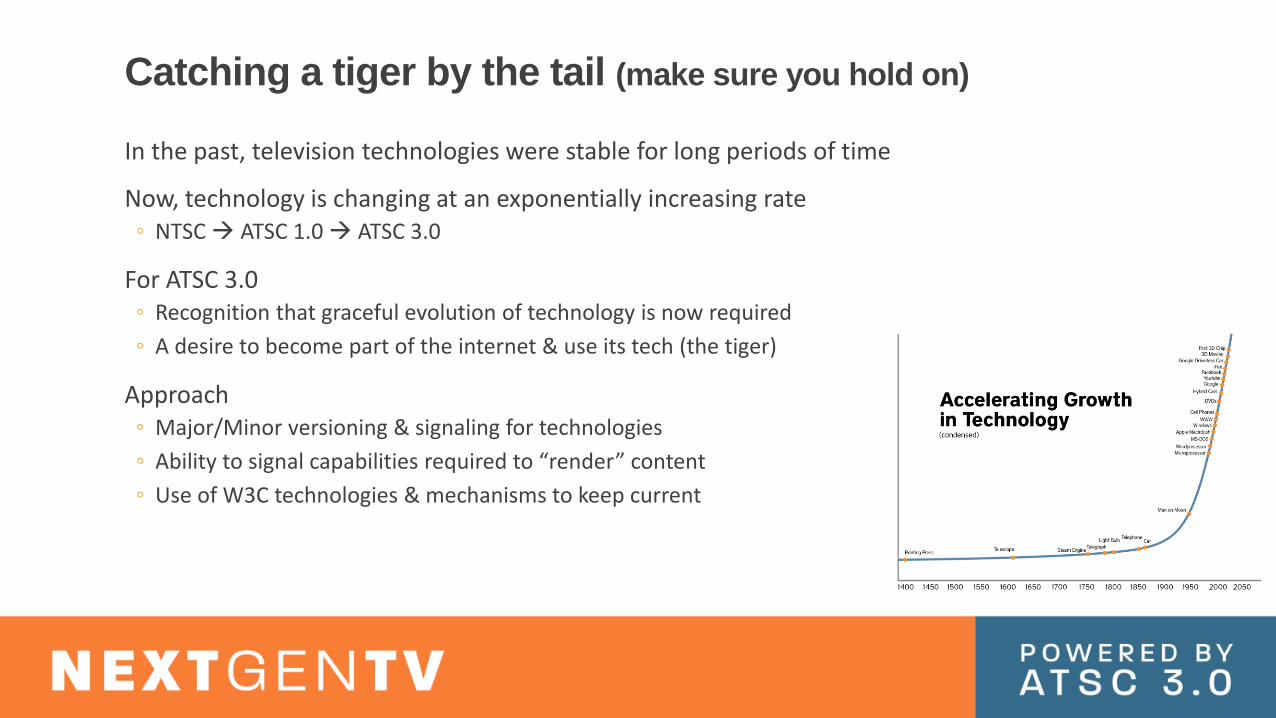
Catching a tiger by the tail (make sure you hold on)
In the past, television technologies were stable for long periods of time
Now, technology is changing at an exponentially increasing rate◦ NTSC ATSC 1.0 ATSC 3.0
For ATSC 3.0◦ Recognition that graceful evolution of technology is now required
◦ A desire to become part of the internet & use its tech (the tiger)
Approach◦ Major/Minor versioning & signaling for technologies
◦ Ability to signal capabilities required to “render” content
◦ Use of W3C technologies & mechanisms to keep current


