
J Artif Organs (2001) 4:161-164 �9 The Japanese Society for Artificial Organs 2001
Akio Kawamura, MD, PhD Motoki Yonekawa, MD, PhD �9 Kazutaka Kukita, MD, PhD Jun-Ichi Meguro, MD, PhD �9 Tohru Tamaki, MD, PhD Mituko Tanaka, MD, PhD �9 Takashi Horie, MD Yoshihiro Masuko, MD �9 Jun-Ichi Iida, MD Yasushi Uchida, MD �9 Noriyuki Murai, MD, PhD Takashi Kaizu, MD �9 Jun Arikura, MD �9 Hiroshi Abe
No-needle blood access device for hemodialysis and no-needle connecting cannula assembly (K-NOBA PATJIAP2983540)
Abstract Our group is developing a no-needle b lood access for main tenance hemodialysis. The device is made f rom ti tanium. The device is connected at the middle par t of the prosthet ic graft A - V shunt. I t has two wells on the condui t and they are closed by shutters. The specially designed cannulas are inser ted in the wells and hemodialysis is per formed. Pat ients have no pain and good QOL. Self- cannulat ion and home dialysis are possible.
Key words No-need le b lood access �9 Hemodia lys is �9 H o m e dialysis
Background
Blood access is the Achi l les ' heel of t rea tment of chronic hemodialysis. Need le puncture every time to the internal shunt for t r ea tment is stressful to pat ients and medical staff. However , an external shunt does not bother a patient . Some complicat ions are thrombosis and infection, which can be make daily life inconvenient.
To overcome these drawbacks of the pr ior shunts, a new blood access device for hemodialysis has been proposed . The b lood access device, given the t rade name Hemasi te , conceptual ly belongs to the external shunt group. ~'2 The Hemas i t e b lood access device is equipped with a tool that has a backflow valve for b lood and is adap ted to acquire a plentiful b lood flow immedia te ly if the tool is simply con- nected to a circuit leading to a dialyzer. The Hemas i te has the advantage that needle puncture is not required, but because of its compl ica ted structure, it is costly and t rouble- some to handle.
Received: September 29, 2000 / Accepted: November 24, 2000
A. Kawamura (~3) �9 M. Yonekawa �9 K. Kukita �9 J. Meguro - T. Tamaki �9 M. Tanaka �9 T. Horie �9 Y. Masuko - J. Iida �9 Y. Uchida �9 N. Murai - T. Kaizu �9 J. Arikura �9 H. Abe Center of Artificial Organs, Sapporo Hokuyu Hospital, 6-6 Higashisapporo, Shiroishi-ku, Sapporo 003-0006, Japan Tel. +81-11-865-0111; Fax +81-11-865-9719
It is therefore an object of the present invention to pro- vide a b lood access device for hemodialysis that does not require needle puncture, has a mechanism of simple struc- ture, can be manufac tured at a relat ively low cost, and is easy to handle, as well as a no-needle connecting cannulas assembly that enables a pat ient to move around with rela- tive f reedom during hemodialysis .
Design
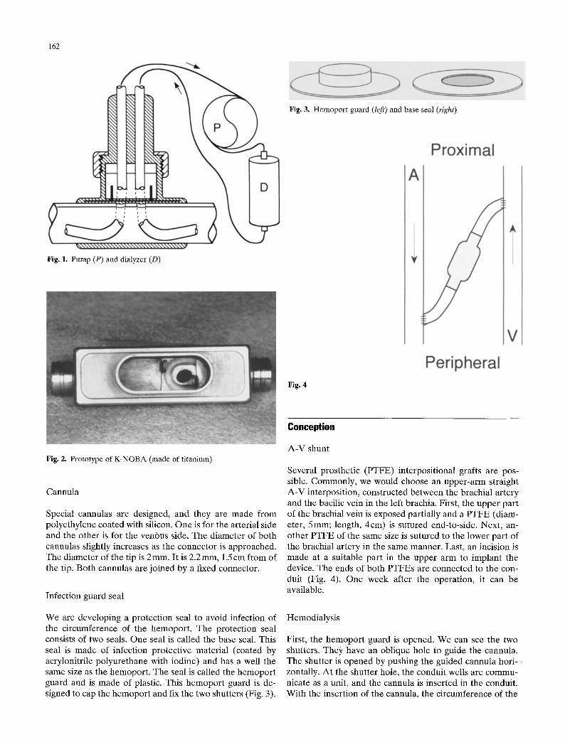
Conceptual ly, this device is an external shunt. The device, however, is implanted under the skin, except the par t of the hemopor t . This device consists of a conduit , two shutters, and a hemopor t . They are made from t i tanium as a unit. The device is pos i t ioned be tween the two prosthet ic grafts. P T E E is connected to a circuit of dialyzer by the specially designed cannulas (Fig. 1).
Blood access
We designed No-Need le B lood Access (K-NOBA) , which is divided mainly into three parts. The lower par t of the t i tanium body is a cylindrical conduit . The length is 4 cm, the outer d iameter is 5 ram, and the inner d iameter is 4ram. The K - N O B A has two wells at the center of the conduit. The inner d iameter is 2 mm. The interval of wells is 5 ram. The circumference of the wells is enclosed by a silicon ring for sealing.
The middle par t is the upper par t of the horizontal con- duit. On this part , a pair of thin sl idable t i tanium shutters are housed within opposed pockets formed respectively and arranged such that they can be opened and closed. W h e n the shutters are open, the well is brought into communica- t ion with the conduit , and when the shutters are closed, the well is brought out of communica t ion with the conduit.
The upper par t is the hemopor t . This par t is posi t ioned at the center of the device and has a cap for fixing and covering shutters and the port. The length is 15mm and the height is 5 ram. This section is outs ide the body (Fig. 2).
162
Fig. 3. Hemoport guard (left) and base seal (right)
Fig. 1. Pump (P) and dialyzer (D)
Fig. 4
Fig. 2. Prototype of K-NOBA (made of titanium)
Cannula
Special cannulas are designed, and they are made from polyethylene coated with silicon. One is for the arterial side and the other is for the venous side. The diameter of both cannulas slightly increases as the connector is approached. The diameter of the tip is 2 ram. It is 2.2 mm, 1.5 cm from of the tip. Both cannulas are joined by a fixed connector.
Infection guard seal
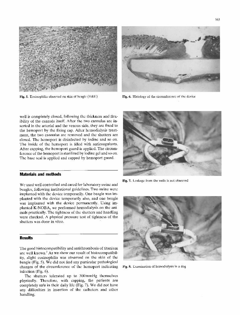
We are developing a protection seal to avoid infection of the circumference of the hemoport. The protection seal consists of two seals. One seal is called the base seal. This seal is made of infection protective material (coated by acrylonitrile polyurethane with iodine) and has a well the same size as the hemoport. The seal is called the hemoport guard and is made of plastic. This hemoport guard is de- signed to cap the hemoport and fix the two shutters (Fig. 3).
Conception
A-V shunt
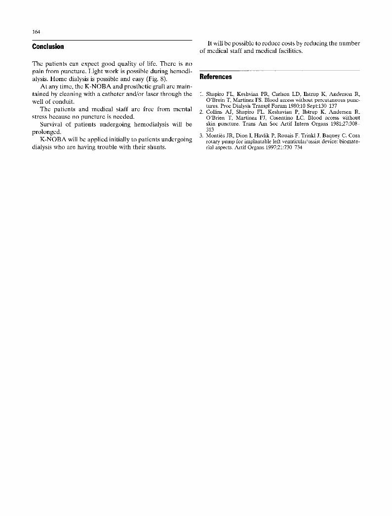
Several prosthetic (PTFE) interpositional grafts are pos- sible. Commonly, we would choose an upper-arm straight A-V interposition, constructed between the brachial artery and the bacilic vein in the left brachia. First, the upper part of the brachial vein is exposed partially and a PTFE (diam- eter, 5mm; length, 4cm) is sutured end-to-side. Next, an- other PTFE of the same size is sutured to the lower part of the brachial artery in the same manner. Last, an incision is made at a suitable part in the upper arm to implant the device. The ends of both PTFEs are connected to the con- duit (Fig. 4). One week after the operation, it can be available.
Hemodialysis
First, the hemoport guard is opened. We can see the two shutters. They have an oblique hole to guide the cannula. The shutter is opened by pushing the guided cannula hori- zontally. At the shutter hole, the conduit wells are commu- nicate as a unit, and the cannula is inserted in the conduit. With the insertion of the cannula, the circumference of the
163
Fig. 5. Eosinophilia observed on skin of beagle (H&E) Fig. 6. Histology of the circumference of the device
well is completely closed, following the thickness and flex- ibility of the cannula itself. After the two cannulas are in- serted in the arterial and the venous side, they are fixed to the hemoport by the fixing cap. After hemodialysis treat- ment, the two cannulas are removed and the shutters are closed. The hemoport is disinfected by iodine and so on. The inside of the hemoport is filled with anticoagulants. After capping, the hemoport guard is applied. The circum- ference of the hemoport is sterilized by iodine gel and so on. The base seal is applied and capped by hemoport guard.
Materials and methods
We used well-controlled and cared for laboratory swine and beagles, following institutional guidelines. Two swine were implanted with the device temporarily. One beagle was im- planted with the device temporarily also, and one beagle was implanted with the device permanently. Using im- planted K-NOBA, we performed hemodialysis on the ani- mals practically. The tightness of the shutters and handling were checked. A physical pressure test of tightness of the shutters was done in vitro.
Fig. 7. Leakage from the wells is not observed
Results
The good histocompatibility and antithrombosis of titanium are well known. 3 As we show our result of histocompatibil- ity, slight eosinophilia was observed on the skin of the beagle (Fig. 5). We did not find any particular pathological changes of the circumference of the hemoport indicating infection (Fig. 6).
The shutters tolerated up to 300mmHg themselves physically. Therefore, with capping, the patients are completely safe in their daily life (Fig. 7). We did not have any difficulties in insertion of the catheters and other handling.
Fig. 8. Examination of hemodialysis in a dog
164
Conclusion It will be possible to reduce costs by reducing the number of medical staff and medical facilities.
The pat ients can expect good quali ty of life. There is no pain f rom puncture. Light work is possible during hemodi- alysis. H o m e dialysis is possible and easy (Fig. 8).
A t any time, the K - N O B A and prosthet ic graft are main- ta ined by cleaning with a ca theter and/or laser through the well of conduit.
The pat ients and medical staff are free from menta l stress because no puncture is needed.
Survival of pat ients undergoing hemodialysis will be prolonged.
K - N O B A will be appl ied initially to pat ients undergoing dialysis who are having t rouble with their shunts.
References
1. Shapiro FL, Keshvian PR, Carlson LD, Ilstrup K, Anderson R, O'Brein T, Martinez FS. Blood access without percutaneous punc- tures. Proc Dialysis Transpl Forum 1980;10 Sept:13~137
2. Collins AJ, Shapiro FL, Keshavian P, Ilstrup K, Andersen R, O'Brien T, Martinez FJ, Cosentino LC. Blood access without skin puncture. Trans Am Soc Artif Intern Organs 1981;27:308- 313
3. Monti6s JR, Dion I, Havlik P, Rouais F, Trinkl J, Baquey C. Cora rotary pump for implantable left ventricular'assist device: biomate- rial aspects. Artif Organs 1997;21:730-734


