NORTHERN TELECOM PRACTICES SECTION 363-2011-500 Issued: 79 12 07
Standard N
DMS-1* DIGITAL MULTIPLEX SYSTEM SYSTEM FAULT LOCATING
CONTENTS PAGE
1. GENERAL. . . . . . . . . . . . . . . . . . . . . . . . I
2. LOCATING SELF-ALARM FAULTS . . . . . . . . . . . . . . . . . . . . . . . . . 3
3. LOCATING AUDIT-ALARM FAULTS . . . . . . . . . . . . . . . . . . . . . . . . . 3
4. LOCATING NO-ALARM FAULTS . . . . . . . . . . . . . . . . . . . . . . . . . 4
1. GENERAL
Scope
1.01 This section describes the procedures for locating and clearing faults in the DMS-1
system. The procedures include checks to verify system performance after a fault has been cleared.
1.02 Reason for Reissue: to add new and revised information.
• DMS-1 is a trademark of Northern Telecom Limited
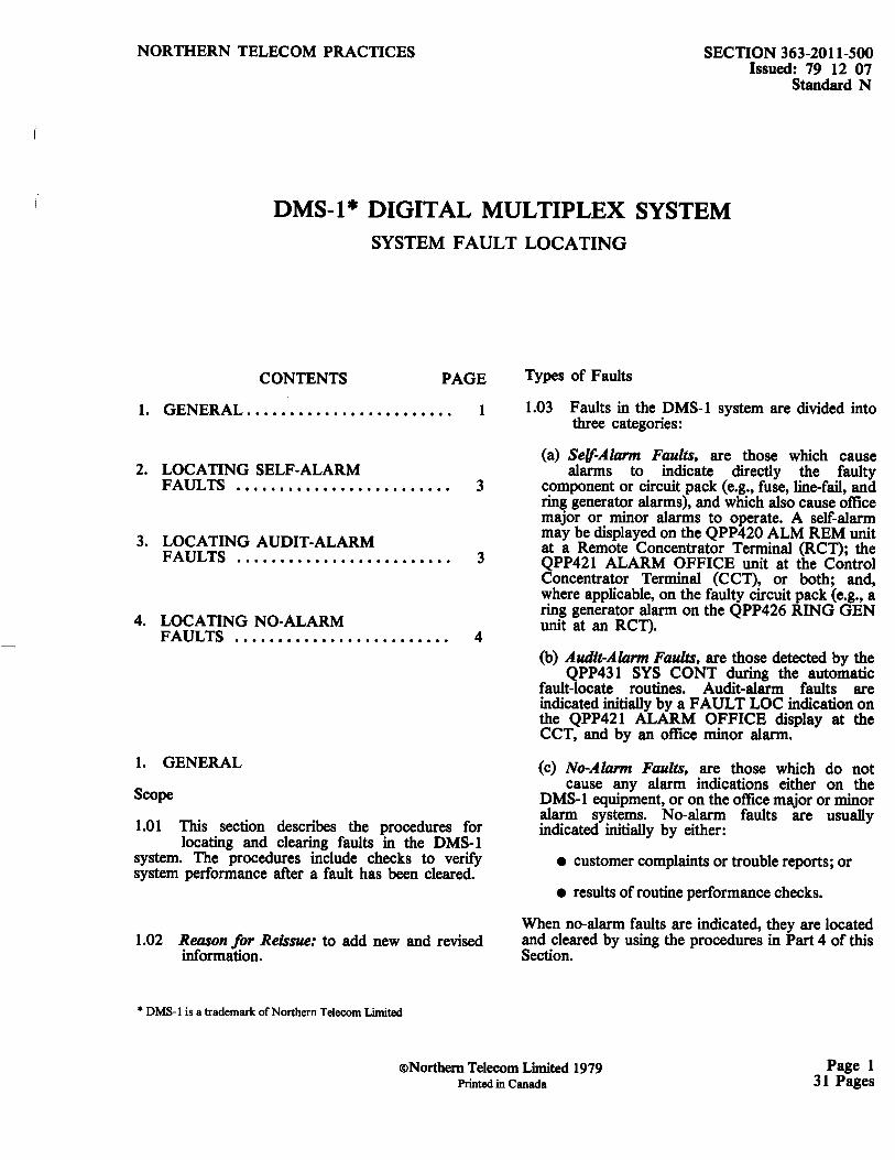
Types of Faults
1.03 Faults in the DMS-1 system are divided into three categories:
(a) Self-Alarm Faults, are those which cause alarms to indicate directly the faulty
component or circuit pack (e.g., fuse, line-fail, and ring generator alarms), and which also cause office major or minor alarms to operate. A self-alarm may be displayed on the QPP420 ALM REM unit at a Remote Concentrator Terminal (RCT); the QPP421 ALARM OFFICE unit at the Control Concentrator Terminal (CCT), or both; and, where applicable, on the faulty circuit pack (e.g., a ring generator alarm on the QPP426 RING GEN unit at an RCT).
(b) Audit-Alarm Faults, are those detected by the QPP431 SYS CONT during the automatic
fault-locate routines. Audit-alarm faults are indicated initially by a FAULT LOC indication on the QPP421 ALARM OFFICE display at the CCT, and by an office minor alarm.
(c) No-Alarm Faults, are those which do not cause any alarm indications either on the
DMS-1 equipment, or on the office major or minor alarm systems. No-alarm faults are usually indicated initially by either:
• customer complaints or trouble reports; or
• results of routine performance checks.
When no-alarm faults are indicated, they are located and cleared by using the procedures in Part 4 of this Section.
®Northern Telecom Limited 1979 Printed in Canada
Page 1 31 Pages

SECTION 363-2011-500
Functions of Indicators
~ MTCE ALM
RCT 1 LED 1 through 23 LED indicates type indicate control of fau It per code faults, per designation at RCT Table A 1 locatio11. (Note)
RCT 2 LED 1 through 23 LED indicates type indicate memory of fault per audit faults per designation at RCT Table B 2 location . (Note)
RCT 3 LED 1 through 23 LED indicates type indicate line of fau It per audit faults, designation at RCT per Table C 3 location . (Note)
RCT4 LED 1 through 23 LED indicates type indicate line of fault per identification designation at R CT faults, per 4 location. (Note) TableD
CCT See Table E LED indicates type of fau Its per designation at CCT location . (Note)
Note .
If FAULT LOC indicator is lit, follow the procedure for locating auditalarm faults given in part 3; use the MTCE column above as a guide .
ALARM OFFICE
• I MTCE : Al ii
1. 0C P FAIL - A
2. DtP F"Ail-B
) . LINE FAIL-A
· • liNE 1'-"A il- 8
S. LI NE FAIL-P
6 . 8YPA SS OP
7. LP 8t( OP
S . T 8A T F
9 . LJN...£ PWR
l O. RIHC CEN
ll . COH PWR
l2 . AC FAIL
ll . 8AT FA ll
14 . 0V£R TE MP
15 . 0PEN DOOR
16 . RINC OIST f
17 . FAULT LOC
18 . ll OET FAIL
u 8 srs caNT 20. 21. 22. 13.
ACO
... ~"""',\ '-
LP TEST u.
QPP411A
363-029
Fig. l - QPP421 ALARM OFFICE- Alarm Analysis
Page 2
J Flowchart 1
}lowohoct 2
Flowchart 3
Flowchart 4
Flowchart 5
Flowchart 6
Flowchart 7
Flowchart 8
Flowchart 9
Flowchart 10
Flowchart 11
Flowchart 12
Flowchart 13
Note
Flowchart 14
Flowchart 15

Basic Fault-Locating Procedure
1.04 When either a self-alarm or an audit-alarm fault occurs, the frrst indication is normally an
office minor or major alarm (audible, visual, or both). When an office alarm does occur, the following steps should be taken to locate and clear the fault. On the QPP421 ALARM OFFICE unit at the CCT:
(1) Momentarily press and release the ACO button to silence the office alarms.
(2) Turn the RCT/CCT selector switch to the CCT or the RCT position indicated by a
lighted Light Emitting Diode (LED). If more than one RCT indicator is lit, set the switch to the lowest numbered RCT indicated by a lighted LED.
(3) Observe the alarm(s) displayed on the unit, and go to the appropriate flowchart as shown
in Fig. 1. If more than one indicator is lit, go to the flowchart indicated by the first lighted LED from the top of the display.
(4) Locate and correct the fault.
(5) Simultaneously press and release the RESTART and RESTART ARM buttons on
each system controller, in turn, to check for any new fault conditions.
(6) Ensure that no other alarm(s) are present at the QPP421 ALARM OFFICE circuit pack.
1.05 Precaution. To prevent loss of clock on the digital line when removing the active QPP431
SYS CONT, the following precaution must be observed:
Verify that the FAIL lamp is on before removing the QPP431; if the lamp is not on, force it on by pressing the RESTART and RESTART ARM buttons simultaneously and holding them pressed while removing the QPP431 from the shelf.
This precaution is not necessary,
(a) if the DMS-1 system is equipped with only one QPP431, since removing the QPP431 at any
time causes total system failure;
(b) on the standby QPP431; the standby can be removed without affecting service.
2. LOCATING SELF-ALARM FAULTS
2.01 Flowcharts 1 through 15 describe the faultlocating procedure to locate self-alarm faults.
SECTION 363-2011-500
2.02 Notes to Flowcharts. The following notes apply to Flowcharts 1 through 15.
Note 1: Ensure that the MTCE/ ALM switch on the QPP421 ALARM OFFICE circuit pack is in the ALM position.
Note 2: Ensure that the RCT/CCT selector switch on the QPP421 ALARM OFFICE circuit pack is in a position indicated by a lighted LED.
Note 3: If the replacement of a circuit pack does not clear the fault, the original circuit pack should be returned to its operating position.
3. LOCATING AUDIT-ALARM FAULTS
3.01 When the FAULT LOC LED on the QPP421 ALARM OFFICE display lights, perform the
following steps in sequence to locate and correct the fault.
(1) Press the ACO button to tum off the audible and visual office alarms and the top-of-bay
lamp.
(2) Switch the MTCE/ ALM switch to the MTCE position.
(3) Tum the RCT/CCT selector switch to the numbered position indicated by a lighted LED.
If more than one LED is lit, set the switch to the lowest number indicated by a lighted LED.
(4) Refer to Table A, B, C, D, or E, as indicated by the selector switch (see Fig. 2). In the table,
locate the maintenance action number corresponding to the ftrst lighted alarm lamp number on the QPP421 ALARM OFFICE display (Fig. 1), and perform the steps listed under the ACTION column.
Table A Table B Table C Table 0
""' r-----'l.- R CT f / """' 2 3 4
I Lamp Indicators
_j
Rotary Knob
Fig. 2 - Maintenance Table Selection
Page 3
SECTION 363-2011-500
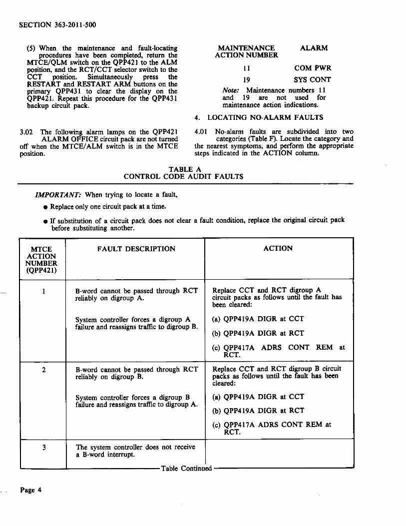
(5) When the maintenance and fault-locating procedures have been completed, return the
MTCE/QLM switch on the QPP421 to the ALM position, and the RCT/CCT selector switch to the CCT position. Simultaneously press the RESTART and RESTART ARM buttons on the primary QPP431 to clear the display on the QPP421. Repeat this procedure for the QPP431 backup circuit pack.
MAINTENANCE ACTION NUMBER
11
19
ALARM
COMPWR
SYS CONT
Note: Maintenance numbers ll and 19 are not used for maintenance action indications.
4. LOCATING NO-ALARM FAULTS
3.02 The following alarm lamps on the QPP421 ALARM OFFICE circuit pack are not turned
off when the MTCE/ ALM switch is in the MTCE position.
4.01 No-alarm faults are subdivided into two categories (Table F). Locate the category and
the nearest symptoms, and perform the appropriate steps indicated in the ACTION column.
TABLE A CONTROL CODE AUDIT FAULTS
IMPORTANT: When trying to locate a fault,
• Replace only one circuit pack at a time.
• If substitution of a circuit pack does not clear a fault condition, replace the original circuit pack before substituting another.
MTCE ACTION NUMBER (QPP421)
2
FAULT DESCRIPTION
B-word cannot be passed through RCT .reliably on digroup A.
System controller forces a digroup A failure and reassigns traffic to digroup B.
B-word cannot be passed through RCT reliably on digroup B.
System controller forces a digroup B failure and reassigns traffic to digroup A.
3 The system controller does not receive a B-word interrupt.
ACTION
Replace CCT and RCT digroup A circuit packs as follows until the fault has been cleared:
(a) QPP419A DIGR at CCT
(b) QPP419A DIGR at RCT
(c) QPP417A ADRS CONT REM at RCT.
Replace CCT and RCT digroup B circuit packs as follows until the fault has been cleared:
(a) QPP419A DIGR at CCT
{b) QPP419A DIGR at RCT
(c) QPP417A ADRS CONT REM at RCT.
'------..L-----------Table Continued-----------------
Page 4

MTCE ACTION NUMBER (QPP421)
4
5
6
7
8
9-10
11
12-18
19
20
21
22
23
SECTION 363-2011-500
TABLE A Continued CONTROL CODE AUDIT FAULTS
FAULT DESCRIPTION ACTION
(a) No B words are returned from the (a) Replace QPP432A B-WD circuit pack. RCT.
(b) Waveform generator failed. (b) After having checked (a), replace QPP418 ADRS CONT OFF.
Replace QPP431 system controller, if alarm is still present.
Left QPP432 B-WD circuit pack Replace left QPP432 B-WD. failure.
Right QPP432 B-WD circuit pack Replace right QPP432 B-WD. failure.
Waveform generator on QPP418 Replace QPP418 ADRS CONT OFF on ADRS CONT OFF in digroup A digroup A. position has failed.
Waveform generator on QPP418 Replace QPP418 ADRS CONT OFF on ADRS CONT OFF in digroup B digroup B. position has failed.
Unassigned.
COM PWR alarm - see 3.02.
Unassigned.
SYS CONT alarm - see 3.02.
Protection switch failure RCTI. Replace QPP428/498 PROT SW RCTl.
Protection switch failure RCT2. Replace QPP428/498 PROT SW RCT2.
Protection switch failure RCT3. Replace QPP428/498 PROT SW RCT3.
Protection switch failure RCT4. Replace QPP428/498 PROT SW RCT4.
Page 5
SECTION 363-2011-500
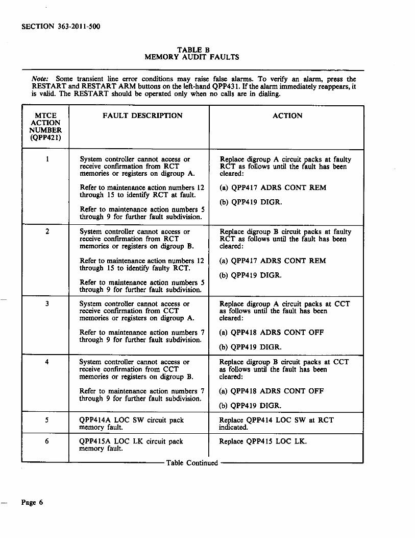
TABLE B MEMORY AUDIT FAULTS
Note: Some transient line error conditions may raise false alarms. To verify an alarm, press the RESTART and RESTART ARM buttons on the left-hand QPP43l. lfthe alarm immediately reappears, it is valid. The RESTART should be operated only when no calls are in dialing.
MTCE FAULT DESCRIPTION ACTION ACTION NUMBER (QPP421)
1 System controller cannot access or Replace digroup A circuit packs at faulty receive confmnation from RCT RCT as follows until the fault has been memories or registers on digroup A. cleared:
Refer to maintenance action numbers 12 (a) QPP417 ADRS CONT REM through 15 to identify RCT at fault.
(b) QPP419 DIGR. Refer to maintenance action numbers 5 through 9 for further fault subdivision.
2 System controller cannot access or Replace digroup B circuit packs at faulty receive confirmation from RCT RCT as follows until the fault has been memories or registers on digroup B. cleared:
Refer to maintenance action numbers 12 (a) QPP417 ADRS CONT REM through 15 to identify faulty RCT.
(b) QPP419 DIGR. Refer to maintenance action numbers 5 through 9 for further fault subdivision.
3 System controller cannot access or Replace digrotif A circuit packs at CCT receive confrrmation from CCT as follows un · the fault has been memories or registers on digroup A. cleared:
Refer to maintenance action numbers 7 (a) QPP418 ADRS CONT OFF through 9 for further fault subdivision.
(b) QPP419 DIGR.
4 System controller cannot access or Replace digroup B circuit packs at CCT receive confrrmation from CCT as follows until the fault has been memories or registers on digroup B. cleared:
Refer to maintenance action numbers 7 (a) QPP418 ADRS CONT OFF through 9 for further fault subdivision.
(b) QPP419 DIGR.
5 QPP414A LOC SW circuit pack Replace QPP414 LOC SW at RCT memory fault. indicated.
6 QPP415A LOC LK circuit pack Replace QPP415 LOC LK. memory fault.
Table Continued
Page 6

MTCE ACTION NUMBER
7
8
9
10
11
12
13
14
15
16
17
18
19
20-23
SECTION 363-2011-500
TABLE B Continued MEMORY AUDIT FAULTS
FAULT DESCRIPTION ACTION
Alarm scan fault. Replace digroup A and B circuit packs at RCT as follows until the fault is cleared:
RCT alarm indications should be (a) QPP417 ADRS CONT REM ignored until this fault has been cleared. (b) QPP419 DIGR
(c) QPP420 ALM REM.
Maintenance operation favlt. (a) Refer to mantenance action numbers 1 and 2 above.
Control codes for maintenance actions (b) Replace QPP420 ALM REM. are not properly recognized or replied to.
Line test access fault. (a) Refer to maintenance action numbers 1 and 2 above.
Control codes for operation of line test (b) Replace QPP417 ADD CONT REM. access relays are not properly recognized or replied to.
Subscriber line test/test extension - Replace QPP423 or QPP447. memory fault.
COM PWR alarm - see 3.02.
Fault at RCTL
Fault at RCT2.
Fault at RCT3.
Fault at RCT4.
System controller memory failure. Replace QPP431 SYS CONT.
Line test office failure. Replace QPP424.
VF fault on QPP450 Test Control. (a) Replace QPP450 TEST CONTROL
(b) Check self-test on replacement QPP450.
SYS CONT alarm - see 3.02.
Unassigned.
Page 7
SECTION 363-2011-SOO
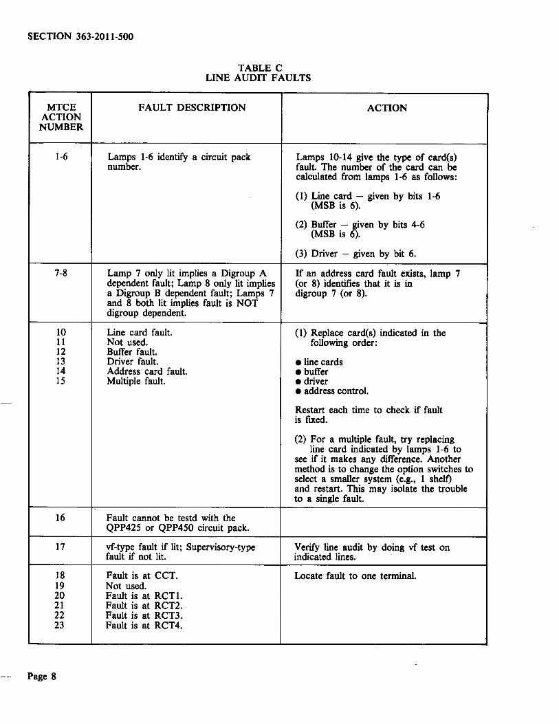
TABLE C LINE AUDIT FAULTS
MTCE FAULT DESCRIPTION ACTION ACTION NUMBER
1-6 Lamps 1-6 identify a circuit pack Lamps 10-14 give the type of card(s) number. fault. The number of the card can be
calculated from lamps 1-6 as follows:
( 1) Line card - given by bits 1-6 (MSB is 6).
(2) Buffer - given by bits 4-6 (MSB is 6).
(3) Driver - given by bit 6.
7-8 Lamp 7 only lit implies a Digroup A If an address card fault exists, lamp 7 dependent fault; Lamp 8 only lit implies (or 8) identifies that it is in a Digroup B dependent fault; Lamps 7 digroup 7 (or 8). and 8 both lit implies fault is NOT digroup dependent.
10 Line card fault. (1) Replace card(s) indicated in the 11 Not used. following order: 12 Buffer fault. 13 Driver fault. eline cards 14 Address card fault. • buffer IS Multiple fault. • driver
• address control.
Restart each time to check if fault is fixed.
(2) For a multiple fault, try replacing line card indicated by lamps 1-6 to
see if it makes any difference. Another method is to change the option switches to select a smaller system (e.g., 1 shelf) and restart. This may isolate the trouble to a single fault.
16 Fault cannot be testd with the QPP42S or QPP450 circuit pack.
17 vf-type fault if lit; Supervisory-type Verify line audit by doing vf test on fault if not lit. indicated lines.
18 Fault is at CCT. Locate fault to one terminal. 19 Not used. 20 Fault is at RCTL 21 Fault is at RCT2. 22 Fault is at RCT3. 23 Fault is at RCT4.
Page 8
SECTION 363-2011-SOO
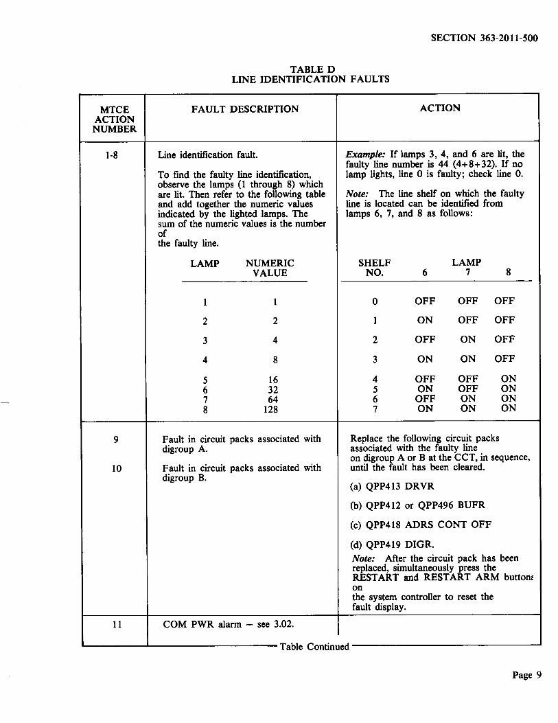
TABLED LINE IDENTIFICATION FAULTS
MTCE ACTION NUMBER
1-8
9
10
FAULT DESCRIPTION
Line identification fault.
To fmd the faulty line identification, observe the lamps (1 through 8) which are lit. Then refer to the following table and add together the numeric values indicated by the lighted lamps. The sum of the numeric values is the number of the faulty line.
LAMP
1
2
3
4
5 6 7 8
NUMERIC VALUE
1
2
4
8
16 32 64
128
Fault in circuit packs associated with digroup A.
Fault in circuit packs associated with digroup B.
11 COM PWR alarm - see 3.02 .
ACTION
Example: If lamps 3, 4, and 6 are lit, the faulty line number is 44 (4+8+32). If no lamp lights, line 0 is faulty; check line 0.
Note: The line shelf on which the faulty line is located can be identified from lamps 6, 7, and 8 as follows:
SHELF LAMP NO. 6 7 8
0 OFF OFF OFF
1 ON OFF OFF
2 OFF ON OFF
3 ON ON OFF
4 OFF OFF ON 5 ON OFF ON 6 OFF ON ON 7 ON ON ON
Replace the following circuit packs associated with the faulty line on digroup A orB at the CCT, in sequence, until the fault has been cleared.
(a) QPP413 DRVR
(b) QPP412 or QPP496 BUFR
(c) QPP418 ADRS CONT OFF
(d) QPP419 DIGR.
Note: After the circuit pack has been replaced, simultaneously press the RESTART and RESTART ARM buttom on the system controller to reset the fault display.
....._ ____ ........._ __________ Table Continued ______________ __.
Page 9
SECTION 363-2011-500
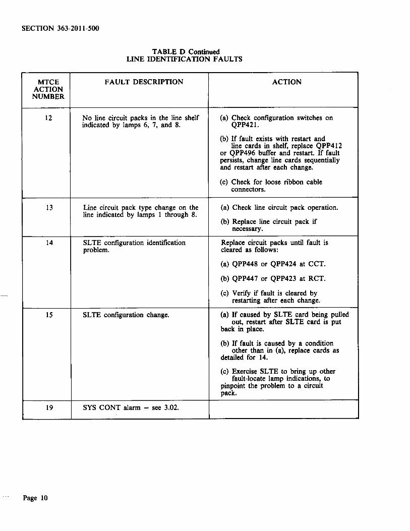
TABLE D Continued LINE IDENTIFICATION FAULTS
MTCE FAULT DESCRIPTION ACTION ACTION NUMBER
12 No line circuit packs in the line shelf (a) Check configuration switches on indicated by lamps 6, 7, and 8. QPP421.
(b) If fault exists with restart and line cards in shelf, replace QPP412
or QPP496 buffer and restart. If fault persists, change line cards sequentially and restart after each change.
(c) Check for loose ribbon cable connectors.
13 Line circuit pack type change on the (a) Check line circuit pack operation. line indicated by lamps 1 through 8.
(b) Replace line circuit pack if necessary.
14 SL TE configuration identification Replace circuit packs until fault is problem. cleared as follows:
(a) QPP448 or QPP424 at CCT.
(b) QPP447 or QPP423 at RCT.
(c) Verify if fault is cleared by restarting after each change.
15 SL TE configuration change. (a) If caused by SLTE card being pulled out, restart after SLTE card is put
back in place.
(b) If fault is caused by a condition other than in (a), replace cards as
detailed for 14.
(c) Exercise SLTE to bring up other fault-locate lamp indications, to
pinpoint the problem to a circuit pack.
19 SYS CONT alarm - see 3.02.
Page 10
SECTION 363-2011-500
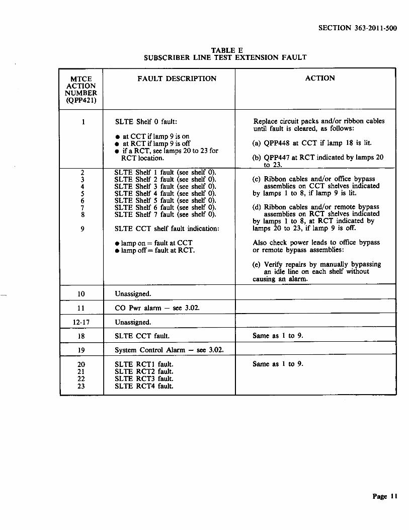
TABLE E SUBSCRIBER LINE TEST EXTENSION FAULT
MTCE FAULT DESCRIPTION ACTION ACTION NUMBER (QPP421)
1 SL TE Shelf 0 fault: Replace circuit packs and/or ribbon cables until fault is cleared, as follows:
• at CCT if lamp 9 is on • at RCT if lamp 9 is off (a) QPP448 at CCT if lamp 18 is lit. • if a RCT, see lamps 20 to 23 for
RCT location. (b) QPP447 at RCT indicated by lamps 20 to 23.
2 SL TE Shelf 1 fault (see shelf 0). 3 SLTE Shelf 2 fault (see shelf 0). (c) Ribbon cables and/or office bypass 4 SLTE Shelf 3 fault (see shelf 0). assemblies on CCT shelves indicated 5 SL TE Shelf 4 fault (see shelf 0). by lamps 1 to 8, if lamp 9 is lit. 6 SLTE Shelf 5 fault (see shelf 0). 7 SLTE Shelf 6 fault (see shelf 0). (d) Ribbon cables and/ or remote bypass 8 SL TE Shelf 7 fault (see shelf 0). assemblies on RCT shelves indicated
by lamps 1 to 8, at RCT indicated by 9 SLTE CCT shelf fault indication: lamps 20 to 23, if lamp 9 is off.
• lamp on= fault at CCT Also check power leads to office bypass • lamp off= fault at RCT. or remote bypass assemblies:
(e) Verify repairs by manually bypassing an idle line on each shelf without
causing an alarm.
10 Unassigned.
11 CO Pwr alarm - see 3.02.
12-17 Unassigned.
18 SL TE CCT fault. Same as 1 to 9.
19 System Control Alarm - see 3.02.
20 SLTE RCTI fault. Same as 1 to 9. 21 SLTE RCT2 fault. 22 SLTE RCT3 fault. 23 SLTE RCT4 fault.
Page 11

SECTION 363-2011-500
CATEGORY
(I) Customer Reports
(2) Maintenance Faults:
2.1 QPP425 or QPP450 Detected Faults
2.2 QPP424 Detected Faults
2.3 QPP434 Traffic Faults
2.4 QPP448 Detected Faults
Page 12
TABLE F NO-ALARM FAULTS
SYMPTOM
(a) No dial tone.
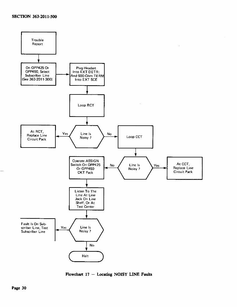
(b) Noisy line.
(c) Telephone does not ring but can originate calls.
When calling another line. connection is broken when terminating line goes off-hook.
Wrong or no long distance bills on 2-party line.
(a) Lines test consistently HIGH or LOW.
(b) No channel assigned when ASGN button operated.
(a) CAL CHECK FAIL lamp lights.
(b) Consistently wrong readings.
(c) Incorrect operation.
(a) Traffic indicators stop counting or count too fast.
Incorrect operation.
ACTION
Refer to Flowchart 16.
Refer to Flowchart 17.
Refer to Flowchart 18.
Replace QPP416 LOC LK DET.
Test ANI detector using System Test - refer to Flowchart 16 and 363-2011-300.
(a) Calibrate using procedures in 363-2011-300.
(b) Replace QPP425 or QPP450.
(a) Replace QPP423 and retest.
(b) Replace QPP423 and retest.
(c) Replace QPP424 and retest.
(a) Replace QPP434.
Replace QPP448 and retest.
No
No
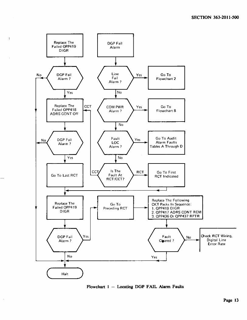
Replace The Failed QPP419
DIGR
Replace The Failed QPP418
ADRS CONT Off
Go To Last RCT
Replace The Failed QPP419
DIGR
No
( __ Ha-lt_)
DGP Fail Alarm
Go To Preceding RCT
Yes
Yes
Yes
RCT
Go To Flowchart 2
Go To Flowchart 8
Go To Audit Alarm Faults
Tables A Through D
Go To First RCT Indicated
Replace The Following CKT Packs In Sequence: 1. QPP419 DIGR
SECTION 363-2011-500
2. QPP417 AD RS CONT REM 3. QPP436 Or QPP437 RPTR
No Check RCT Wiring, Digital Line Error Rate
Flowchart 1 - Locating DGP FAIL Alarm Faults
Page 13
SECTION 363-2011-500
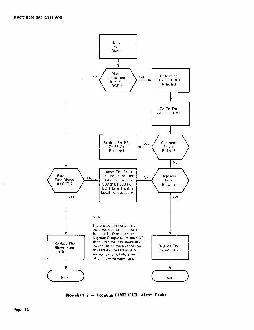
Repeater Fuse Blown At CCT?
Yes
Replace The Blown Fuse
(Note)
( __ Halt_)
No
No
Line Fail
Alarm
Yes
Replace F4, F5, Yes Or F6 As Required
Locate The Fault On The Failed Line.
Refer To Section 368·2101·503 For LD·1 Line Trouble
Locating Procedure
Note:
If a protection switch has occurred due to the blown
No
fuse on the Digroup A or Digroup B repeater at the CCT, the switch must be manually locked, using the switches on the OPP429 or OPP499 Pro· tection Switch, before replacing the repeater fuse.
Determine The First RCT
Affected
Go To The Affected R CT
Yes
Replace The Blown Fuse
C..., __ H_a_lt __ _.)
Flowchart 2 - Locating LINE FAIL Alarm Faults
Page 14

Bypass OP Alarm
Go To The RCT Indicated
Check Wiring For Shorts
Yes
Restart The QPC85 5/12V
Converters
Replace Each No OPC85 5/12V
Converter
Replace OPP420 Yes Alarm Remote
No
SECTION 363-2011-500
Measure The Output Voltage
On Each OPC85 5/12V Converter
Replace OPP428 Or OPP498
PROT SW Remote
No
( __ Halt_)
Flowchart 3 - Locating BYPASS OP Alarm Faults
Page 15
SECTION 363-2011-500
Page 16
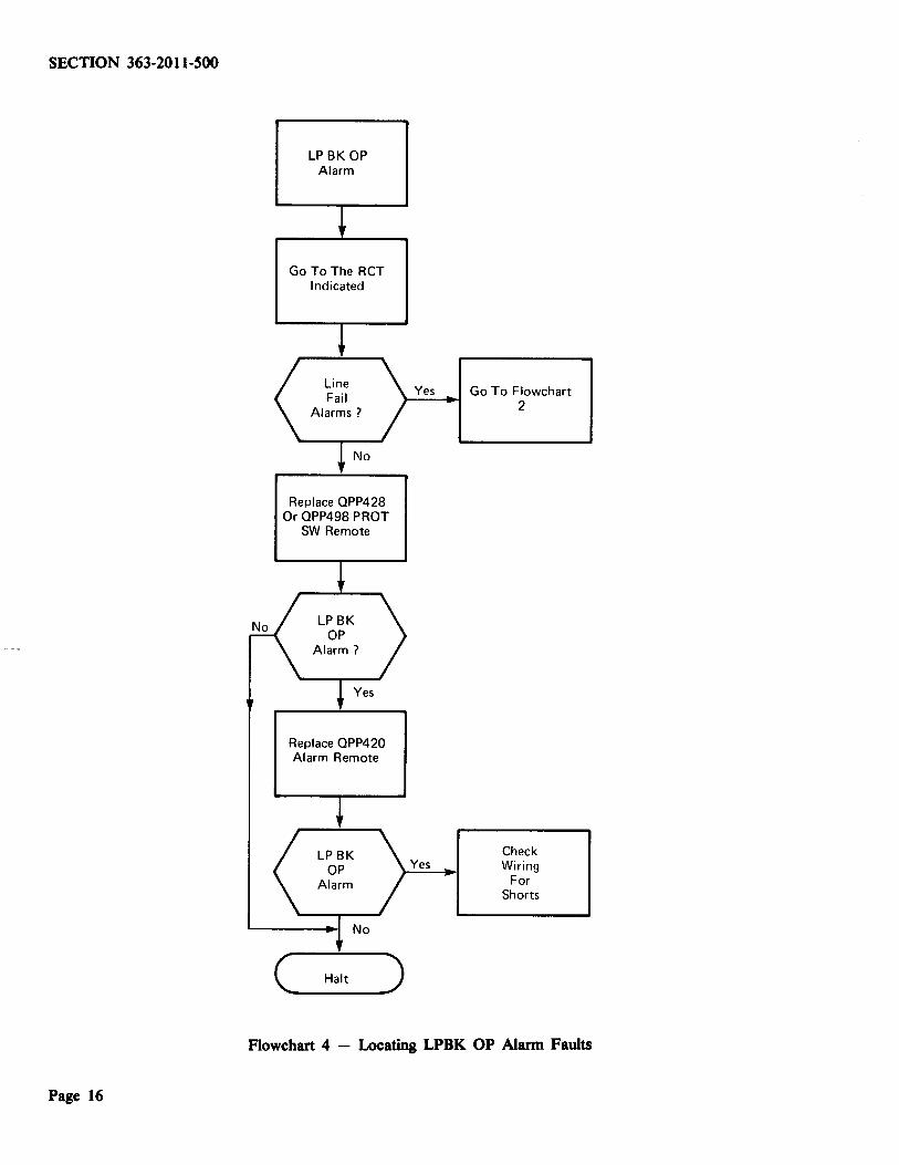
LP BK OP Alarm
Go To The RCT Indicated
Replace QPP428 Or QPP498 PROT
SW Remote
Replace QPP420 Alarm Remote
( __ Halt_)
Yes Go To Flowchart
Yes
2
Check Wiring
For Shorts
Flowchart 4 - U>cating LPBK OP Alarm Faults
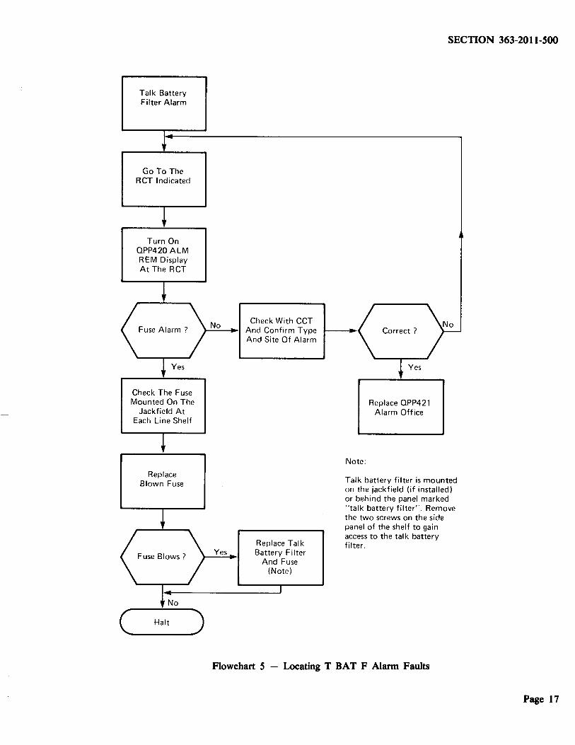
Talk Battery Filter Alarm
Go To The RCT Indicated
Turn On OPP420 ALM REM Display At The RCT
SECTION 363-2011-500
No Check With CCT )-....:..__.,~1 And Confirm Type
Check The Fuse Mounted On The
Jackfield At Each Line Shelf
Replace Blown Fuse
('--_Halt_)
Yes
And Site Of Alarm
Replace Talk Battery Filter
And Fuse (Note)
Note:
Replace OPP421 Alarm Office
Talk battery filter is mounted on the jackfield (if installed) or behind the panel marked "talk battery filter'·. Remove the two screws on the side panel of the shelf to gain access to the talk battery filter.
Flowchart 5 - Locating T BAT F Alarm Faults
Page 17

SECTION 363-2011-500
Replace OPP412 Or OPP496
BUFR On Same Line Shelf
Press Reset On The OPP439 L PWR
CONV
Measure The Voltages At The OPP439
L PWR CONV NTP 363-2011-205 Or 363-2011-206
1. Remove Line CKT Packs One-By-One Until Voltages Are Ok. Replace Faulty
Line CKT Packs 2. Inspect Wiring For
Loss Of Clock And Frame Pulses
{See SD7208A-01 And SD7209A-01)
Replace Fuse
Replace OPP439 L PWR CONV And
Press Reset
Replace OPP421 Alarm Office
Yes
Line PWR Alarm
Press Reset On Line PWR CONV
No
c ___ Ha-lt ~)
Flowchart 6 - Locating LINE PWR Alarm Faults
Page 18
Restart OPP431 SYSCONT
Go To The Alarmed RCT
Turn On QPP420 ALM REM Display
Check With CCT And Confirm Type And Site Of Alarm
Replace OPP420 ALM REM Or
QPP421 Alarm Office
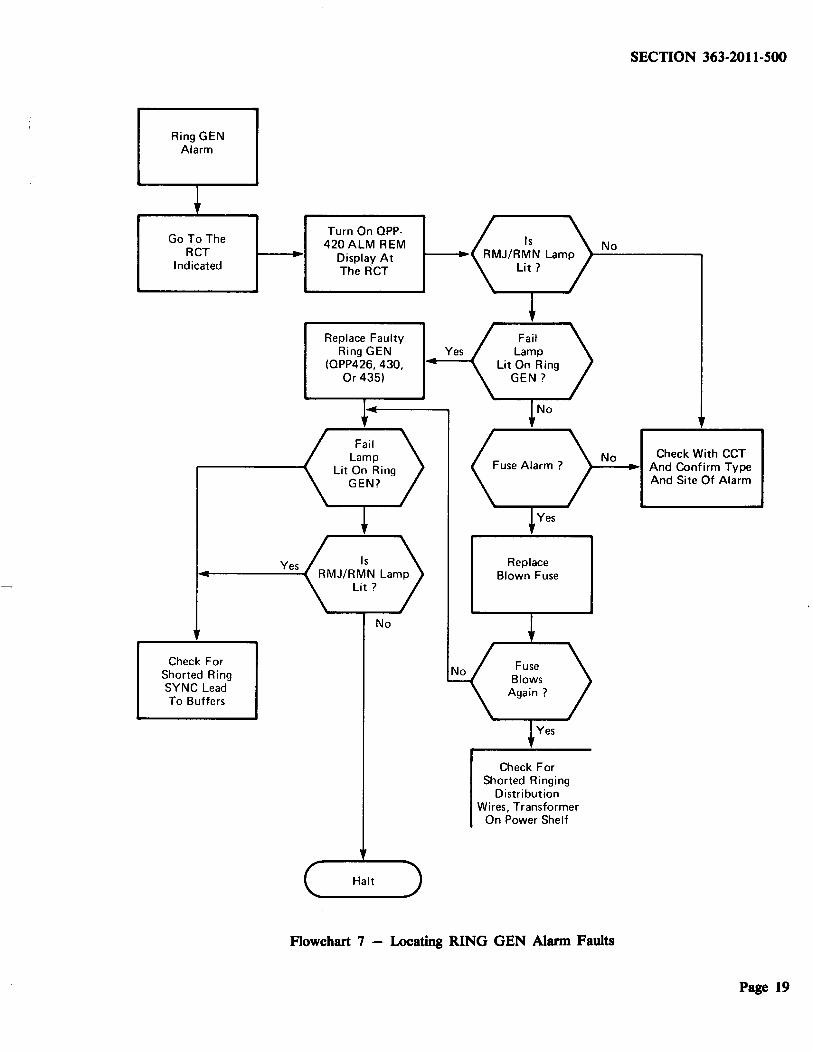
Ring GEN Alarm
Go To The RCT
Indicated
Check For Shorted Ring SYNC Lead To Buffers
Yes
Turn On OPP-420ALM REM
Display At The ACT
Replace Faulty Ring GEN Yes
(0PP426, 430, Or 435)
No
(_Halt_)
Replace Blown Fuse
Check For Shorted Ringing
Distribution Wires, Transformer
On Power Shelf
SECTION 363-2011-SOO
No
No Check With CCT ~----~1 And Confirm Type
And Site Of Alarm
Flowchart 7 - I.A>cating RING GEN Alarm Faults
Page 19
SECTION 363-2011-500
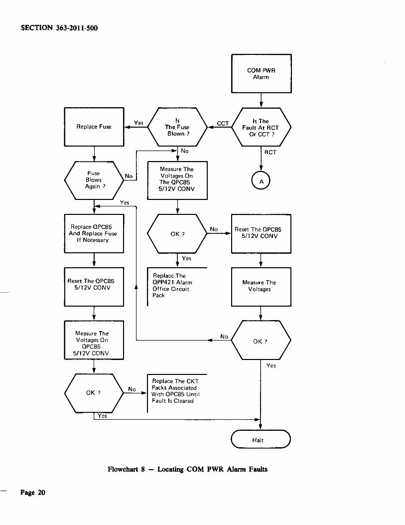
Replace Fuse
Replace OPC85 And Replace Fuse
If Necessary
Reset The OPC85 5/12V CONV
Measure The Voltages On
OPC85 5/12V CONV
Yes Is The Fuse Blown?
Measure The Voltages On The OPC85 5/12V CONV
Replace The OPP421 Alarm Office Circuit Pack
Replace The CKT No Packs Associated
r----.~1 With OPC85 Until Fault Is Cleared
No
COM PWR Alarm
RCT
Reset The OPC85 r--~1 5/12V CONV
No
Measure The Voltages
Yes
C .... __ H_al_t __ ... )
Flowchart 8 - Locating COM PWR Alarm Faults
Page 20

Go To The RCT
Indicated
Turn On OPP420 ALM REM Display At The RCT
Check With CCT And Confirm Type And Site Of Alarm
Measure The Voltages On The OPC85 5/12V CONV
Reset The 0PC85 5/12V Converter
Measure The Voltages
Yes
Yes
Yes
No
Replace The OPP420 Alarm Remote Circuit Pack
Replace The CKT Packs Associated With OPC85 Until Fault Is Cleared
No
SECTION 363-2011-SOO
Replace Fuse
Replace OPC85 And Replace Fuse
If Necessary
Reset The OPC85 Power
Converter
Measure The Voltages On The OPC85 5/12V CONV
C, __ H_a_lt __ _,)
Flowchart 8 Continued - Locating COM PWR Alarm Faults
Page 21

SECTION 363-2011-500
AC Fail Alarm
Go To The RCT
Indicated
Turn On OPP-420ALM REM
Display At The RCT
Refer To The Maintenance
Practices Of The Power Plant
Page 22
Replace OPY-352A Control Card In The
Rectifier
Yes
Measure AC Power
Voltage
Use Auxiliary Generator Until
AC Voltage Returns
Check For Yes Shorted Alarm
Leads, Alarm Relay Failure
Flowchart 9 - Locating AC FAIL Alarm Faults
Check With CCT And Confirm
Type And Site Of Alarm
Turn The Circuit
Breaker On
Turn Off OPP-420 ALM REM
Display
( __ Halt_)

BAT Fail Alarm
Go To The RCT
Indicated
Turn On QPP420 ALM REM Display
At The RCT
Refer To The Maintenance
Practices Of The Power Plant
Inspect Rectifier And
Wiring For
No
Yes
Replace QPY353A Circuit Pack In The Rectifier
Check With CCT ,_....;;_-.~• And Confirm Type
Yes
No
And Site Of Alarm
Replace QPY352A Control Card In
The Rectifier
Adjust Rectifier For Correct
Operation Using NTP 363-2011-214
Yes
Flowchart 10 - Locating BAT FAIL Alarm Faults
SECTION 363-2011-SOO
Go To Chart 9
Page 23
SECTION 363-2011-SOO
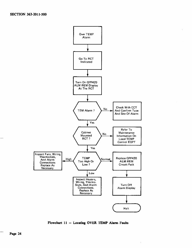
Inspect Fans, Wiring, Thermostats, And Alarm High
Connections Replace As Necessary
Over TEMP Alarm
Go To RCT Indicated
Turn On OPP420 ALM REM Display
At The RCT
Inspect Heaters, Wiring, Thermo. Stats, And Alarm
Connections. Replace As Necessary
No Check With CCT )-'..:..:;....---.~ And Confirm Type
No
Normal
And Site Of Alarm
Refer To Maintenance
Information On Local TEMP
Control EOPT
Replace OPP420 ALM REM
Circuit Pack
Turn Off Alarm Display
C..., __ H_a_lt __ .,)
Flowchart 11 - Locating OVER TEMP Alarm Faults
Page 24
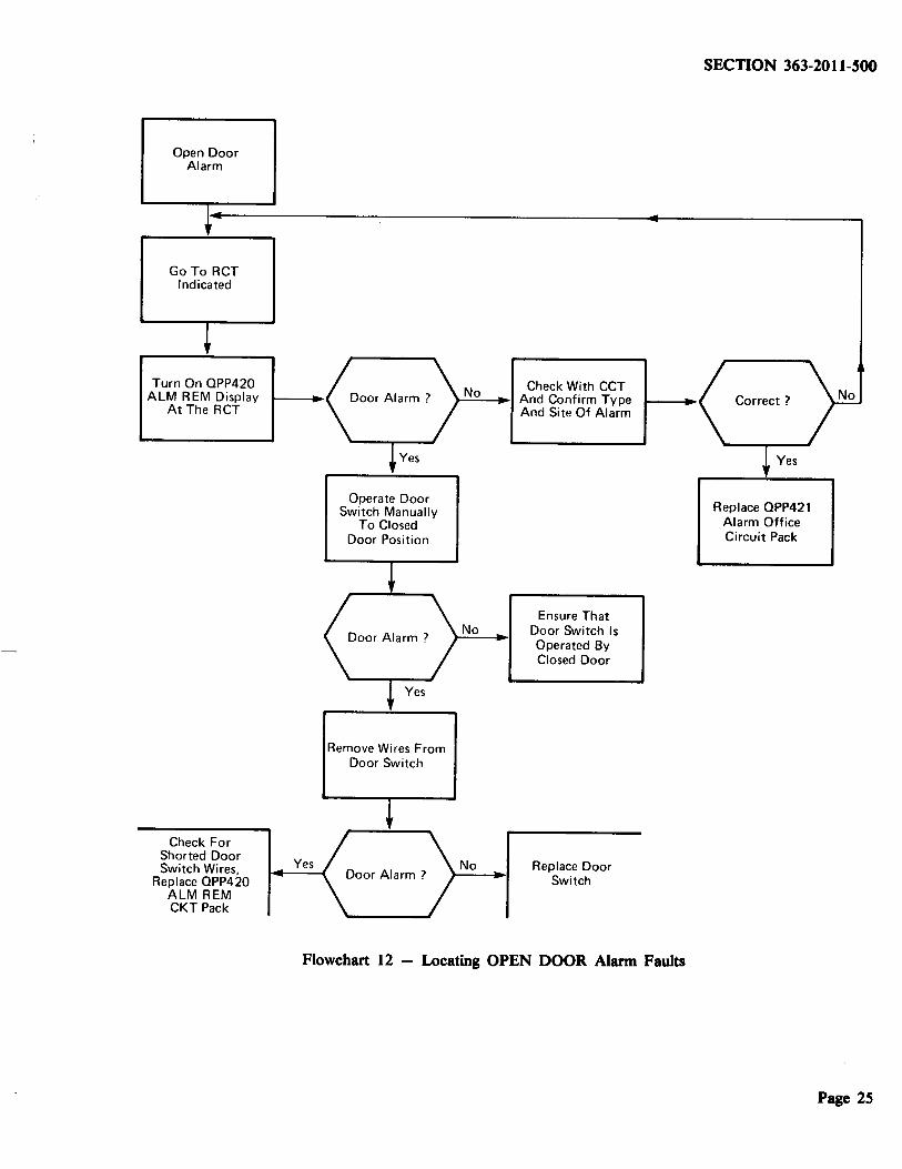
Open Door Alarm
Go To RCT Indicated
Turn On OPP420 ALM REM Display
At The RCT
Check For Shorted Door Switch Wires,
Replace OPP420 ALM REM CKT Pack
Yes
Operate Door Switch Manually
To Closed Door Position
Remove Wires From Door Switch
Check With CCT rN;..:;o_,._, And Confirm Type
No
No
And Site Of Alarm
Ensure That Door Switch Is Operated By Closed Door
Replace Door Switch
Flowchart 12 - Locating OPEN DOOR Alarm Faults
SECTION 363-2011-SOO
Replace OPP421 Alarm Office Circuit Pack
Page 2S

SECTION 363-2011-SOO
Ring DIST F Alarm
I f
Go To The Turn On The Alarm No Check With CCT
Alarmed ACT QPP420 ALM REM Indicated? And Confirm Type And Site Of Alarm
+ Yes
Replace No Fuse Blown ~ OPP422 At ACT On OPP422? Correct?
+Yes Yes
Replace Fuse At CCT, On OPP422 Replace RNG DIST OPP421
+
Replace OPP4 12 Test Each Sub
Or OPP496 Buffer Yes
Fuse Blows ? No Line On Line
Shelf Affected On Affected Shelf For Short TG. RG
+ Ring Each Sub Line No Short
Replace Fuse On Affected Shelf Found On TG, RG?
+ • Yes
Yes (\' Fuse Blows? Repair Short Fuse Blows?
~No +Yes
Inspect Ring Replace Affected Distrib Wiring For Shorts And Repair Line CKT Pack
+ Inspect Alarm Test New Line
Alarm Yes Wiring; Replace CKT Pack; See Indicated? OPP420 Alarm 363-2011-206,
Office 363-2011-213
I No
C Halt ) -----Flowchart 13 - Locating RING DIST F Alarm Faults
Page 26

SECTION 363-2011-SOO
LL DET Fail Alarm On
OPP421 ALM Off CKT Pack
+ Replace OPP416
LOC LK DET
+ Perform Procedures
Outlined In NTP Section 363-2011-213 To Check Local Link
Operation
Flowchart 14 - Locating LL DET FAIL Alarm Faults
Page 27
SECTION 363-2011-500
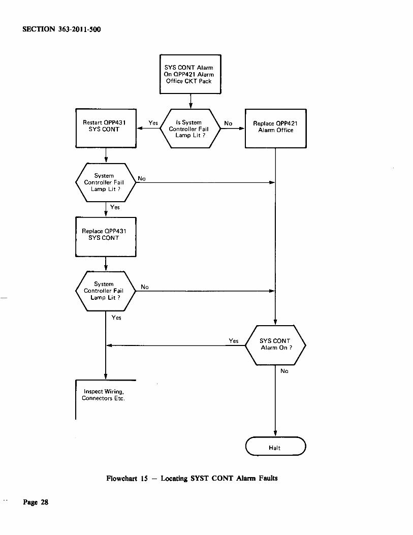
Restart OPP431 SYSCONT
Replace OPP431 SYSCONT
Yes
Inspect Wiring, Connectors Etc.
Yes
No
No
SYS CONT Alarm On OPP421 Alarm Office CKT Pack
No
Yes
Replace QPP421 Alarm Office
SYSCONT Alarm On?
No
C, __ H_a_lt __ _,)
Flowchart 15 - Locating SYST CONT Alarm Faults
Page 28
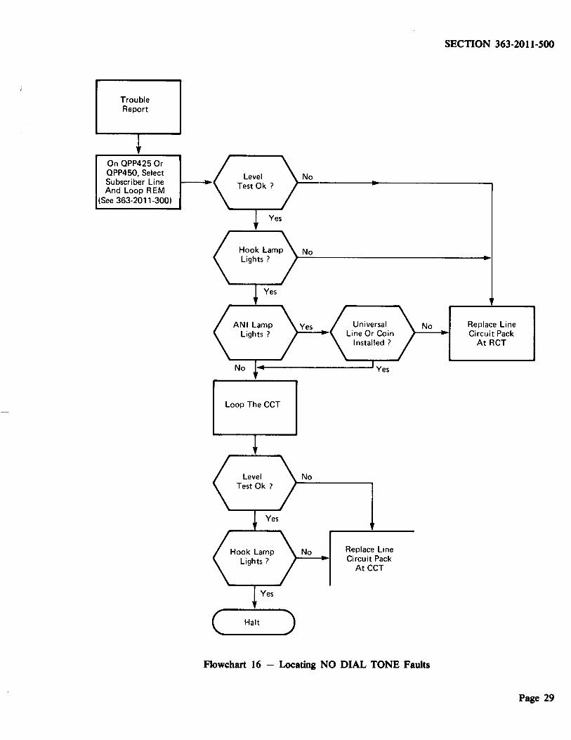
Trouble Report
On QPP425 Or QPP450, Select Subscriber Line And Loop REM
(See 363-2011-300)
Loop The CCT
(....__Ha-lt ___.,.)
No
No Replace Line Circuit Pack
AtCCT
SECTION 363-2011-500
No Replace Line Circuit Pack
AtRCT
Flowchart 16 - Locating NO DIAL TONE Faults
Page 29
SECTION 363-2011-500
Trouble Report
On OPP425 Or OPP450, Select Subscriber Line
(See 363-2011-300)
At RCT, Replace Line Circuit Pack
Fault Is On Sub· scriber Line, Test Subscriber Line
Page 30
Yes
Plug Headset Into EXT DETR:
And 900-0hm TERM Into EXT SCE
Loop RCT
Operate ASSIGN Switch On OPP425
Or OPP450 CKT Pack
Listen To The Line At Line Jack On Line Shelf, Or At Test Center
(....__H-alt_)
No Loop CCT
No
Flowchart 17 - Locating NOISY LINE Faults
Yes At CCT, Replace Line Circuit Pack
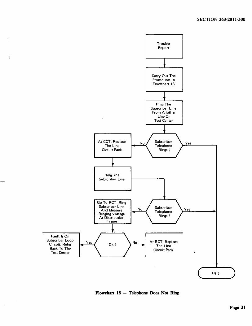
Fault Is On Subscriber Loop
Circuit. Refer Back To The Test Center
Yes
At CCT, Replace The Line
Circuit Pack
Ring The Subscriber Line
Go To RCT, Ring Subscriber Line
And Measure Ringing Voltage At Distribution
Frame
No
No
No
Trouble Report
Carry Out The Procedures In Flowchart 16
Ring The Subscriber Line From An.other
Line Or Test Center
Subscriber Telephone
Rings?
At RCT, Replace The Line
Circuit Pack
Flowchart 18 - Telephone Does Not Ring
SECTION 363-2011-500
Yes
Yes
Halt
Page 31


