
Numerical Simulation of Slug Generation at a
V-Shaped Elbow Between Inclined Pipes
Motoki Irikura 1,2
Munenori Maekawa 1
Shigeo Hosokawa 2
Akio Tomiyama 2
1 Chiyoda Corporation
2 Graduate School of Engineering, Kobe University
13th
International Conference on
MULTIPHASE FLOW IN INDUSTRIAL PLANTS
17-19 September 2014, Sestri Levante (Genova), Italy

13th International Conference on MULTIPHASE FLOW IN INDUSTRIAL PLANTS Numerical Simulation of Slug Generation at a V-Shaped Elbow Between Inclined Pipes Sep. 18th, 2014
1
Contents
1. Background and Motivation
2. Previous Experimental Work
3. Numerical Method
4. Slug Generation and Flow Patterns
5. Slug Characteristics
Gas Liquid
Slug generation at a V-shaped elbow

13th International Conference on MULTIPHASE FLOW IN INDUSTRIAL PLANTS Numerical Simulation of Slug Generation at a V-Shaped Elbow Between Inclined Pipes Sep. 18th, 2014
2
(Image: Marc Shandro via flickr.com , http://gasline.alaska.gov/)
(Image: http://www.offshore-mag.com, http://www.dpoperators.org,
http://pipeliner.com.au)
Oil and Gas Transport Pipeline
Background
Overland pipeline Offshore pipeline

13th International Conference on MULTIPHASE FLOW IN INDUSTRIAL PLANTS Numerical Simulation of Slug Generation at a V-Shaped Elbow Between Inclined Pipes Sep. 18th, 2014
3
Background
In such hilly-terrain pipelines, there are V-shaped elbows
between descending and ascending pipes.
Flow pattern and flow characteristics of oil and gas two-phase
flow varies at V-shaped elbow
Liquid slugs are often generated at V-shaped elbows

13th International Conference on MULTIPHASE FLOW IN INDUSTRIAL PLANTS Numerical Simulation of Slug Generation at a V-Shaped Elbow Between Inclined Pipes Sep. 18th, 2014
4
Gas
Liquid
Significant pressure fluctuation
Overflow in separator
Reduction of transport performance
For the piping design and execution of appropriate operation procedure, predicting slug generation and their characteristics is important
Slug flow in horizontal, vertical and inclined piping have been received much attention.
Knowledge on the slugging at a V-shaped elbow is scarce.
Background
Liquid Slugs at a V-shaped Elbow

13th International Conference on MULTIPHASE FLOW IN INDUSTRIAL PLANTS Numerical Simulation of Slug Generation at a V-Shaped Elbow Between Inclined Pipes Sep. 18th, 2014
5
To give reasonable predictions for this phenomena,
three-dimensional simulation is required
Gas
Liquid
Background
Liquid Slugs at a V-shaped Elbow
Flow field of terrain induced slugging is three-dimensional

13th International Conference on MULTIPHASE FLOW IN INDUSTRIAL PLANTS Numerical Simulation of Slug Generation at a V-Shaped Elbow Between Inclined Pipes Sep. 18th, 2014
6
[Numerical Method]
• Two-fluid model
• The free-surface model for the interfacial area density
Objectives
Three-dimensional numerical simulation was carried out to
examine its applicability to prediction of slug generation at a V-
shaped elbow and slug characteristics.
Gas
Liquid

13th International Conference on MULTIPHASE FLOW IN INDUSTRIAL PLANTS Numerical Simulation of Slug Generation at a V-Shaped Elbow Between Inclined Pipes Sep. 18th, 2014
7
θ θ
Test section
Ring type electrode
Mixing section
Flow meter Valve Mhono
pump
Tank
Filter Critical flow nozzle
Pressure regulator valve
Air filter
Cooler
Compressor
Tank
θ θ
l Insulant
Electrode 1 2 1
50mm 50mm
400 mm 800 mm
12 00 mm
Ring-type electrode
Flow
Test Fluids: Water and Air D = 20 mm
θ = 3˚, 5˚, 7˚
JG = 0.095 – 1.041 m/s
JL = 0.087 – 1.034 m/s
Air
Water
Separator Plate
Previous Work (Hosokawa and Tomiyama, 2003)
Experimental Apparatus
Test Section

13th International Conference on MULTIPHASE FLOW IN INDUSTRIAL PLANTS Numerical Simulation of Slug Generation at a V-Shaped Elbow Between Inclined Pipes Sep. 18th, 2014
8
0.5 1
0.5
1
0
Stratified-Slug
Stratified-Plug
Stratified-Semi-Slug Slug-Slug
Slug-Plug
<JL> (m/s)
<JG
> (m
/s)
D =20mm
θ = 5˚
Ascending pipe Descending pipe
Flow direction
Previous Work (Hosokawa and Tomiyama, 2003)
Flow Pattern in the Ascending Pipe
Flow direction
Stratified-Slug
Ascending pipe Descending pipe
Flow Pattern Map Target

13th International Conference on MULTIPHASE FLOW IN INDUSTRIAL PLANTS Numerical Simulation of Slug Generation at a V-Shaped Elbow Between Inclined Pipes Sep. 18th, 2014
9
θ θ
50mm 50mm
400 mm 800 mm
12 00 mm
Flow
Previous Work (Hosokawa and Tomiyama, 2003)
Measured Liquid Profile
l
0 1 20
10
20
= 20 mm = 5° = 0.61 m/s = 0.22 m/s
= 800-25 mm = 800+25 mm
Time (sec)
Liq
uid
lev
el (
mm
)
D
JG
JL
ll

13th International Conference on MULTIPHASE FLOW IN INDUSTRIAL PLANTS Numerical Simulation of Slug Generation at a V-Shaped Elbow Between Inclined Pipes Sep. 18th, 2014
θcos056.0log135.0θsin35.0ρ
ρ07.1 10
Eo
gDJJV
L
LGS
94.32.3exp,
LG
LU
U
SS
JJ
J
D
L
L
Vf
S
G
GU
S
V
J
L
L
α
11
Slug Velocity VS :
Slug Frequency fS :
Slug Length LS :
(Gas Volume Fraction αG ) 227.0625.0α
LG
G
GJJ
J
D = 20, 30, 40 mm
θ = 3˚, 5˚, 7˚
JG = 0.087 - 1.034 m/s
JL = 0.095 - 1.041 m/s
10
Previous Work (Hosokawa and Tomiyama, 2003)
Correlation for Slug Characteristics

13th International Conference on MULTIPHASE FLOW IN INDUSTRIAL PLANTS Numerical Simulation of Slug Generation at a V-Shaped Elbow Between Inclined Pipes Sep. 18th, 2014
11
)(||ρ8
1LGLGGLifL iG i AC VVVVFF
LiA α
LGGL ρ5.0ρ5.0ρ
5.3fC
])([ν T
kktk t VV τ
δκσ nF ss
Mass :
Momentum :
Governing Equations
Closure Models
Interfacial force :
Area density :
Density :
Friction coeff. :
Numerical Method
kk
s
kk
k ik t
T
kkkk
kk
kkk τP
t αραρ]})({[να
α
1
ρ
1)(
FFgVVVV
V
0
kk
k
tV
where k : gas or liquid
Turbulent stress :
Surface tension :
Free-surface treatment (Egorov, 2004; Vallée et al., 2005; Höhne et al., 2011)
Commercial Software CFX13 was used.
The k-ε model for the two-phase mixture was used for
turbulent viscoisity νt .
The Continuum Surface Force Model (Brackbill, 1992) was used for the
surface tension.

13th International Conference on MULTIPHASE FLOW IN INDUSTRIAL PLANTS Numerical Simulation of Slug Generation at a V-Shaped Elbow Between Inclined Pipes Sep. 18th, 2014
12
100D 100D Inlet
z
x
z
y
Water
Air
Number of cell : 54,000
Time step: 0.005 s
Time duration: 30 - 60 s
Calculation time: 4 – 6 d / run
CPU: Intel Xeon(2.9GHz, 4GB-RAM)
Parallel Core: 4 cores
Simulation Model
Calculation Model
Mesh
θ θ
Inlet
Constant velocity
Outlet
Constant pressure D = 20, 30, 40 mm
θ = 3˚, 5˚, 7˚
Close-up of V-section

13th International Conference on MULTIPHASE FLOW IN INDUSTRIAL PLANTS Numerical Simulation of Slug Generation at a V-Shaped Elbow Between Inclined Pipes Sep. 18th, 2014
13
D = 20 mm
θ = 5˚
JG = 0.60 m/s
JL = 0.22 m/s
Result Computed Liquid Distribution
Ascending pipe Descending pipe
Stratified-Slug
0
Tim
e (s
)
1
2
αL 1 0
l/D 40 50 60 70 80 90 30 20 10 0
0.5 1
0.5
1
0
Stratified-Slug
Stratified-Plug
Stratified-Semi-Slug Slug-Slug
Slug-Plug
<JL> (m/s)
<JG
> (m
/s)

13th International Conference on MULTIPHASE FLOW IN INDUSTRIAL PLANTS Numerical Simulation of Slug Generation at a V-Shaped Elbow Between Inclined Pipes Sep. 18th, 2014
14
Measured Predicted
Result Computed Liquid Profile @ l/D = 40
0 1 20
10
20
= 20 mm = 5° = 0.61 m/s = 0.22 m/s
= 800-25 mm = 800+25 mm
Time (sec)
Liq
uid
lev
el (
mm
)
D
JG
JL
ll
0 1 20
10
20
= 20 mm = 5° = 0.61 m/s = 0.22 m/s
= 800-25 mm = 800+25 mm
Time (sec)L
iquid
lev
el (
mm
)
D
JG
JL
ll

13th International Conference on MULTIPHASE FLOW IN INDUSTRIAL PLANTS Numerical Simulation of Slug Generation at a V-Shaped Elbow Between Inclined Pipes Sep. 18th, 2014
15
D = 20 mm
θ = 5˚
JG = 0.2 m/s
JL = 0.4 m/s
Result Computed Liquid Distribution
Ascending pipe Descending pipe
Stratified-Plug
0.5 1
0.5
1
0
Stratified-Slug
Stratified-Plug
Stratified-Semi-Slug Slug-Slug
Slug-Plug
<JL> (m/s)
<JG
> (m
/s)
0
Tim
e (s
)
1
2
l/D 40 50 60 70 80 90 30 20 10 0
αL 1 0

13th International Conference on MULTIPHASE FLOW IN INDUSTRIAL PLANTS Numerical Simulation of Slug Generation at a V-Shaped Elbow Between Inclined Pipes Sep. 18th, 2014
16
D = 20 mm
θ = 5˚
JG = 1.0 m/s
JL = 0.2 m/s
Result Computed Liquid Distribution
Ascending pipe Descending pipe
Stratified-Semislug
0.5 1
0.5
1
0
Stratified-Slug
Stratified-Plug
Stratified-Semi-Slug Slug-Slug
Slug-Plug
<JL> (m/s)
<JG
> (m
/s)
0
Tim
e (s
)
1
2
l/D 40 50 60 70 80 90 30 20 10 0
αL 1 0

13th International Conference on MULTIPHASE FLOW IN INDUSTRIAL PLANTS Numerical Simulation of Slug Generation at a V-Shaped Elbow Between Inclined Pipes Sep. 18th, 2014
17
Flow Pattern Map
Stratified-Plug
Stratified-Slug
Slug-Slug Stratified-Semi-slug
Slug-Plug
0 0.5 10
0.5
1
(m/s)
(m/s
)
JL
J G
Predicted flow pattern Stratified-Plug Stratified-Slug Stratified-Semi-slug
D = 20 mm
θ = 5˚

13th International Conference on MULTIPHASE FLOW IN INDUSTRIAL PLANTS Numerical Simulation of Slug Generation at a V-Shaped Elbow Between Inclined Pipes Sep. 18th, 2014
18
Slug Characteristics
0 1 20
1
2 = 20 mm = 5°
(m/s)
(m/s
)
=0.2 m/s Correlation Predicted
=0.4 m/s Correlation Predicted
=0.62 m/s Correlation Predicted
D
JL
JL
JL
JG
VS
0 1 20
10
20 = 20 mm = 5°
(m/s)
(1/s
)
=0.2 m/s Correlation Predicted
=0.4 m/s Correlation Predicted
=0.62 m/s Correlation Predicted
D
JL
JL
JL
JG
f S
0 0.5 1 1.5 20
0.5
1 = 20 mm = 5°
(m/s)
=0.2 m/s Correlation Predicted
=0.4 m/s Correlation Predicted
=0.62 m/s Correlation Predicted
D
JL
JL
JL
JG
LS /L
U
Slug Velocity Slug Frequency Slug Length
(non -dimensional)
Dependence on JG and JL D = 20 mm
θ = 5˚

13th International Conference on MULTIPHASE FLOW IN INDUSTRIAL PLANTS Numerical Simulation of Slug Generation at a V-Shaped Elbow Between Inclined Pipes Sep. 18th, 2014
19
Slug Characteristics
Slug Velocity Slug Frequency
Comparison between measured and predicted results
0 1 20
1
2
Measured and predicted (m/s)
Co
rrel
atio
n (
m/s
)
VS
-15%
+15%
Measured Predicted
= 20 mm = 3°, 5°, 7°
D
0 10 200
10
20
Measured and predicted (1/s)
Corr
elat
ion
(1
/s)
fS
+20%
-20%
Measured Predicted
= 20 mm = 3°, 5°, 7°
D
0 0.5 10
0.5
1
Measured and predicted
Co
rrel
atio
n
LS/LU
Measured Predicted
+20%
-20% = 20 mm = 3°, 5°, 7°
D
D = 20 mm
θ = 3˚, 5˚, 7˚
Slug Length
(non -dimensional)

13th International Conference on MULTIPHASE FLOW IN INDUSTRIAL PLANTS Numerical Simulation of Slug Generation at a V-Shaped Elbow Between Inclined Pipes Sep. 18th, 2014
20
Summary Three-dimensional numerical simulation of slugs generated at a V-shaped
elbow was carried out. The results are summarized as follows:
The two-fluid model with free surface treatment was able to
predict the slug generation at the V-shaped elbow and slug
growth and collapse in the ascending pipe.
The model gave reasonable predictions for the effects of the
gas and liquid volume fluxes on slug characteristics.
Since the pipe diameters studied here are relatively small compared with those
in practical systems, validation of the method for slug flow in large-size pipes is
required in the future.

13th International Conference on MULTIPHASE FLOW IN INDUSTRIAL PLANTS Numerical Simulation of Slug Generation at a V-Shaped Elbow Between Inclined Pipes Sep. 18th, 2014
21
END

13th International Conference on MULTIPHASE FLOW IN INDUSTRIAL PLANTS Numerical Simulation of Slug Generation at a V-Shaped Elbow Between Inclined Pipes Sep. 18th, 2014
22

13th International Conference on MULTIPHASE FLOW IN INDUSTRIAL PLANTS Numerical Simulation of Slug Generation at a V-Shaped Elbow Between Inclined Pipes Sep. 18th, 2014
23
Effect of Mesh
0 0.50
0.5
Predicted
Corr
elat
ion
LS/LU
54,000 cells 320,000 cells
+20%
-20% = 20 mm = 5°D
0 0.5 1 1.50
0.5
1
1.5
Predicted (m/s)
Co
rrel
atio
n (
m/s
)
VS
-15%
+15%
54,000 cells 320,000 cells
= 20 mm = 5°D
0 5 100
5
10
Predicted (1/s)
Corr
elat
ion
(1
/s)
fS
+20%
-20%
54,000 cells 320,000 cells
= 20 mm = 5°D
Slug Velocity Slug Frequency Slug Length
(non -dimensional)
D = 20 mm
θ = 5˚

13th International Conference on MULTIPHASE FLOW IN INDUSTRIAL PLANTS Numerical Simulation of Slug Generation at a V-Shaped Elbow Between Inclined Pipes Sep. 18th, 2014
24
Effect of friction coefficient Cf
Slug Velocity Slug Frequency Slug Length
(non -dimensional)
D = 20 mm
θ = 5˚
0 0.50
0.5
Predicted
Corr
elat
ion
LS/LU
= 0.5 = 3.5 = 10 = 50
+20%
-20%
Cf
0 0.5 1 1.50
0.5
1
1.5
Predicted (m/s)
Co
rrel
atio
n (
m/s
)
VS
-15%
+15%
= 0.5 = 3.5 = 10 = 50
Cf
0 5 100
5
10
Predicted (1/s)
Corr
elat
ion
(1/s
)
fS
+20%
-20%
= 0.5 = 3.5 = 10 = 50
Cf

13th International Conference on MULTIPHASE FLOW IN INDUSTRIAL PLANTS Numerical Simulation of Slug Generation at a V-Shaped Elbow Between Inclined Pipes Sep. 18th, 2014
Slug Velocity VS :
Slug Frequency fS :
Slug Length LS :
(Gas Volume Fraction αG )
25
Previous Work (Hosokawa and Tomiyama, 2003)
Correlation for Slug Characteristics
θcosθsinρ
ρhv
L
LGoS FrFrgD
JJCV
Based on the drift flux model:
D = 20, 30, 40 mm
θ = 3˚, 5˚, 7˚
JG = 0.087 - 1.034 m/s
JL = 0.095 - 1.041 m/s
Slip Velocity (Bendiksen, 1984)
θcos056.0log135.0θsin35.0ρ
ρ07.1 10
Eo
gDJJV
L
LGS
94.32.3exp,
LG
LU
U
SS
JJ
J
D
L
L
Vf
S
G
GU
S
V
J
L
L
α
11
227.0625.0α
LG
G
GJJ
J
Dimensionless slug unit length LU/D was assumed to
relates to the dimensionless liquid volume flux JL/(JL+JG)
Based on mass conservation of slug unit
Measured αG was proportional to the dimensionless gas
volume flux JL/(JL+JG)

13th International Conference on MULTIPHASE FLOW IN INDUSTRIAL PLANTS Numerical Simulation of Slug Generation at a V-Shaped Elbow Between Inclined Pipes Sep. 18th, 2014
26
)(||ρ8
1LGLGGLifL iG i AC VVVVFF
LiA α
LGGL ρ5.0ρ5.0ρ
5.3fC
])([ν T
kktk t VV τ
δκσ nF ss
Mass :
Momentum :
Governing Equations
Closure Models
Interfacial Force :
Area Density :
Density :
Friction Coeff. :
Numerical Method
kk
s
kk
k ik t
T
kkkk
kk
kkk τP
t αραρ]})({[να
α
1
ρ
1)(
FFgVVVV
V
0
kk
k
tV
where k : gas or liquid
Turbulent Stress :
Surface Tension :
Free-surface treatment (Egorov, 2004; Vallée et al., 2005; Höhne et al., 2011)
Commercial Software CFX13 was used.
The k-ε model for the two-phase mixture (ANSYS, 2010) was
used for turbulent viscoisity νt .
The Continuum Surface Force Model (Brackbill, 1992) was used for the surface
tension.

13th International Conference on MULTIPHASE FLOW IN INDUSTRIAL PLANTS Numerical Simulation of Slug Generation at a V-Shaped Elbow Between Inclined Pipes Sep. 18th, 2014
27
])σ
νν[(ε kk
kk
k
tmm P
tV
m
T
mmtP VVV ])([νk
]ε)σ
νν[(
εεε
ε 2
2ε1ε
k
kkk
tmm CPC
tV
m
GLLGGGm
ρ
ραρα VVV
m
LLLGGGm
ρ
ναναν
εν μ
2kCt
Numerical Method
Turbulence Model : k-ε Model for Two-Phase Mixture (ANSYS, 2010)
Turbulent Kinetic Energy k:
Turbulent Dissipation Rate ε:
where
Turbulent Kinematic Viscosity νt:
Production Rate of Shear-induced Turbulence Pk:
Mixture Kinematic Viscosity νm:
Mixture Velocity Vm:
13th International Conference on MULTIPHASE FLOW IN INDUSTRIAL PLANTS Numerical Simulation of Slug Generation at a V-Shaped Elbow Between Inclined Pipes Sep. 18th, 2014
28
|α|δ L
LL
L
L
LL
L α|α||α|
α
|α|
1
|α|
ακ n
Numerical Method
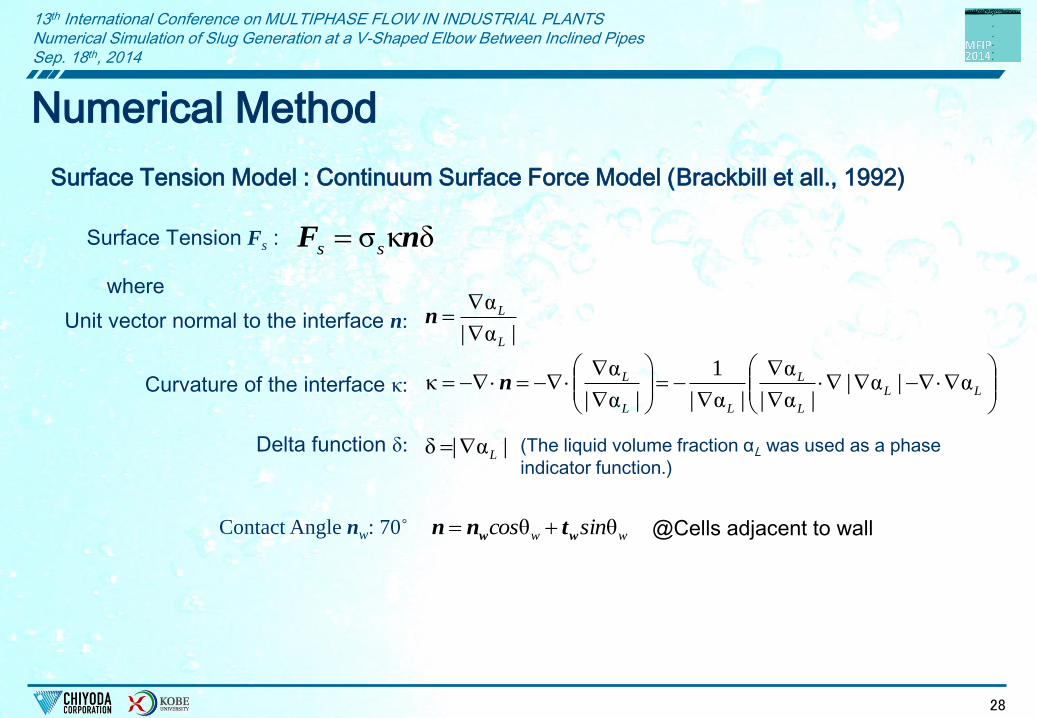
Surface Tension Model : Continuum Surface Force Model (Brackbill et all., 1992)
where
Unit vector normal to the interface n:
Curvature of the interface κ:
Delta function δ:
δκσ nF ss Surface Tension Fs :
|α|
α
L
L
n
(The liquid volume fraction αL was used as a phase
indicator function.)
Contact Angle nw: 70˚ ww sincos θθ ww tnn @Cells adjacent to wall
13th International Conference on MULTIPHASE FLOW IN INDUSTRIAL PLANTS Numerical Simulation of Slug Generation at a V-Shaped Elbow Between Inclined Pipes Sep. 18th, 2014
29
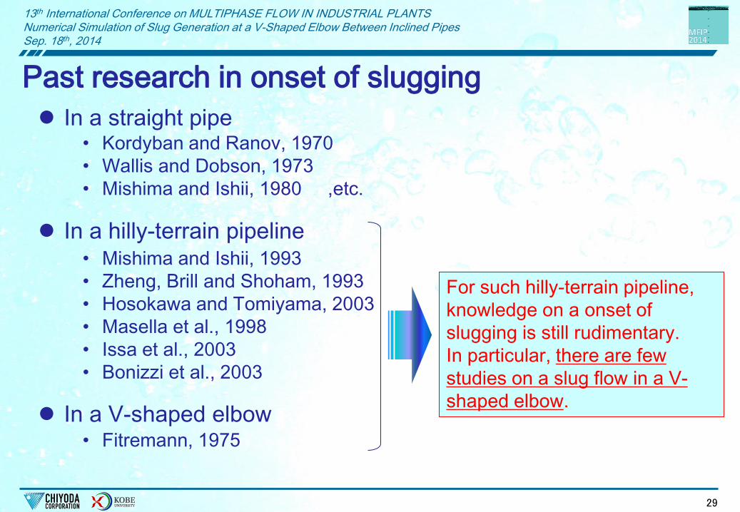
Past research in onset of slugging
In a straight pipe
In a hilly-terrain pipeline
• Kordyban and Ranov, 1970
• Wallis and Dobson, 1973
• Mishima and Ishii, 1980 ,etc.
• Mishima and Ishii, 1993
• Zheng, Brill and Shoham, 1993
• Hosokawa and Tomiyama, 2003
• Masella et al., 1998
• Issa et al., 2003
• Bonizzi et al., 2003
In a V-shaped elbow • Fitremann, 1975
For such hilly-terrain pipeline,
knowledge on a onset of
slugging is still rudimentary.
In particular, there are few
studies on a slug flow in a V-
shaped elbow.

13th International Conference on MULTIPHASE FLOW IN INDUSTRIAL PLANTS Numerical Simulation of Slug Generation at a V-Shaped Elbow Between Inclined Pipes Sep. 18th, 2014
30


