Download - Office Network and Hospitality Cabling
date/time
Office Network and Hospitality Cabling
Lau Chin Jien
Field Application Engineer

date/timeDecember 2, 2014
Introductions to Premises Cabling Standards
December 2, 2014
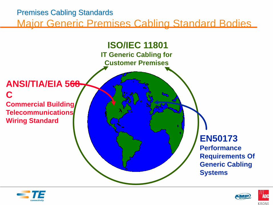
Premises Cabling Standards
Major Generic Premises Cabling Standard Bodies
ISO/IEC 11801IT Generic Cabling for
Customer Premises
ANSI/TIA/EIA 568-
CCommercial Building
Telecommunications
Wiring Standard
EN50173Performance
Requirements Of
Generic Cabling
Systems
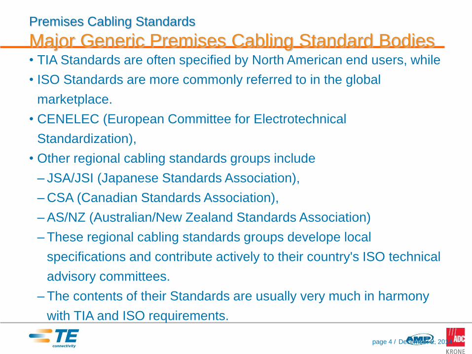
• TIA Standards are often specified by North American end users, while
• ISO Standards are more commonly referred to in the global
marketplace.
• CENELEC (European Committee for Electrotechnical
Standardization),
• Other regional cabling standards groups include
– JSA/JSI (Japanese Standards Association),
– CSA (Canadian Standards Association),
– AS/NZ (Australian/New Zealand Standards Association)
– These regional cabling standards groups develope local
specifications and contribute actively to their country's ISO technical
advisory committees.
– The contents of their Standards are usually very much in harmony
with TIA and ISO requirements.
Premises Cabling Standards
Major Generic Premises Cabling Standard Bodies
December 2, 2014page 4 /
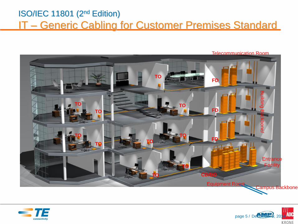
ISO/IEC 11801 (2nd Edition)
IT – Generic Cabling for Customer Premises StandardB
uild
ing B
ackb
on
e/
TO
Telecommunication Room
CD/BD
Entrance
Facility
Campus Backbone
TO
TO
TO
TO
TO
TO
TO
TO
TOFD
FD
FD
Equipment Room
December 2, 2014page 5 /

ISO/IEC 11801 (2nd Edition)
Distributors• Distributors should be located such
that the resulting cable lengths are
consistent with the channel
performance requirements of the
standard and that the maximum
allowed cabling lengths are not
exceeded.
• In any case the maximum channel
length in horizontal cabling is 100 m.
• Total maximum channel
length of horizontal, building
backbone and campus
backbone cabling is 2000 m
• The functions of multiple distributors may be combined, when needed. For
example the functions of campus, building and floor distributor can be
combined.
December 2, 2014page 6 /
date/time
Healthcare Facility Telecommunications
Infrastructure Standard - TIA-1179
Healthcare Facility Telecommunications Infrastructure
The TIA-1179 standard specifies requirements for telecommunications
infrastructure intended to support a wide range of healthcare facilities
and systems to include cabling, topology, pathways and work areas,
and the devices attached to it.

Pathways and spaces
• Recommends minimum of two diverse pathways from the entrance
facility to the equipment room to allow the user to segregate network-
type applications such as voice and data from other critical
applications that are more specific to healthcare, such as imaging and
diagnostic communications.
• Pathway redundancy
• Larger equipment rooms and telecommunications rooms (TRs) with a
minimum of 130 square feet.
Recommended Cables
• Recommends a minimum of Category 6 copper cabling for horizontal
runs (Category 6A for new builds), as well as 50-micron multimode
fiber-optic cabling for high-bandwidth transmissions. (Eg. Computed
tomography (CT) scans and magnetic resonance imaging (MRI)
exams)
• Multimode and singlemode fiber-optic cabling and should be
redundant.
• Recommendations is to segregate cables based on the applications
or services they are supporting. (Eg. color-code cables and
connectors so they can be identified easily )
• Choice of cable heavily affected by the environment (eg.
electromagnetic interference (EMI), temperature swings from area to
area, and the possibility of contact with chemicals and other gases)
Work Area Environments (ANSI/TIA-1179)
• Patient Services
• Surgery/Procedure/Operating Rooms
• Emergency
• Ambulatory Care
• Women’s Health
• Diagnostic and Treatment
• Caregiver
• Service/Support
• Facilities
• Operations
• Critical Care

Work Area
Each work area is given a recommended density of Low, Medium or
High, which provides a guideline as to how many information outlets
are appropriate for the space.
• Low density is defined to be between 2 – 6 outlets
• Medium density is 6 – 14 outlets
• High density work areas should have > 14 outlets
• Recommends the use of multi-user telecommunications outlet
assemblies (MUTOAs) to provide the flexibility of adding up to 24
additional outlets to a work area but does not recommend the use of
consolidation points (CPs) to add outlets to a work area.

TIA-1179 Healthcare Standard vs. TIA-568-C Commercial
Building Standards
Room Size—TIA-1179 recommends a growth factor of 100% when determining room size for
Equipment Rooms (ERs) and specifies that Telecommunications Rooms (TRs) should be sized at 12
m2 (130 ft2) or larger.
Cabling Practices—TIA-1179 specifies a minimum of two diverse pathways to be provided between
ERs and entrance facilities and to each TR or Telecommunications Enclosure (TE) for critical care
areas.
Work Area Location—TIA-1179 does not require outlets to be located together and location of
outlets should consider the various uses. For example, while commercial building standards place
outlets at 18 inches above the finished floor, outlets in healthcare facilities may best be located at
bedside height to support patient monitoring, nurse call and other systems.
Work Area Outlet density—TIA-1179 recommends higher work area outlet densities based on the
function at each location. Commercial building standards recommend only a minimum of two work
area outlets.
Recognized Transmission Media-- TIA-1179 recommends using the highest performing media
whenever possible and specifies Category 6a cabling capable of supporting 10Gb/s for all new
healthcare installations.

TIA-1179 Healthcare Standard vs. TIA-568-C Commercial
Building Standards
Infection Control Requirements (ICR)—TIA-1179 recommends labeling spaces subject to ICR. The
standard also states that TEs may be a better option for ICR areas and should be a suitable material
when installed in surgical and other sterile environments.
The Use of MUTOAs—TIA-1179 does not recommend the use of MUTOAs for new construction, but
states that MUTOAs may be advantageous for renovation of existing healthcare facilities in areas
where any significant collection of equipment or modalities are moved or reconfigured frequently.
Security and Segregation—TIA-1179 recommends the use of segregated networks when necessary
to ensure adequate support of life and safety protocols. The standard recommends considering the
use of colored cables, colored jacks or keyed connectivity to maintain segregation.
Environmental Considerations—TIA-1179 recognizes that some locations in healthcare facilities
may be sensitive to atmospheric contamination, high levels of EMI, radiation, high temperature,
chemicals, etc. To minimize these effects, the standard recommends that solutions, design and
installation should be compatible with the surrounding environment.

date/time
Challenges Healthcare Facility Cabling
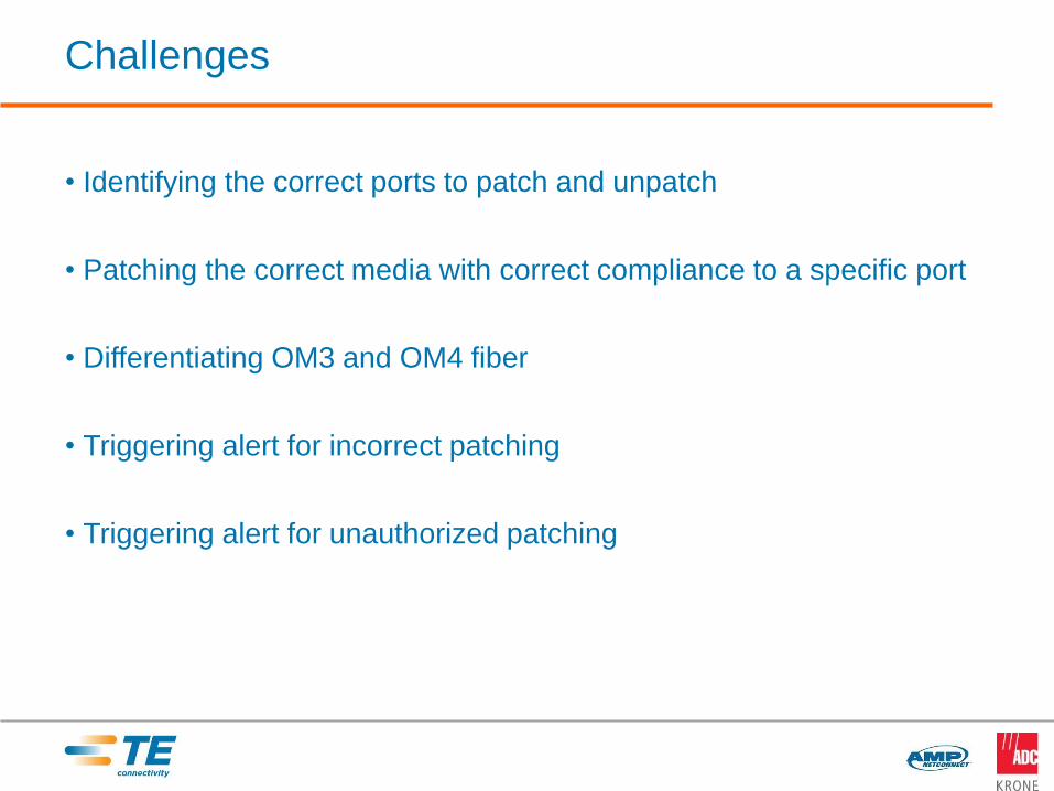
Challenges
• Identifying the correct ports to patch and unpatch
• Patching the correct media with correct compliance to a specific port
• Differentiating OM3 and OM4 fiber
• Triggering alert for incorrect patching
• Triggering alert for unauthorized patching
date/time
TE Quareo Technology

The Importance of Securing the Physical Layer
In today’s environment, there is no way to view, manage or audit the
physical layer (cables, connection points and their paths). This means
the physical layer is not subject to the same security policy
compliance as higher layers of the network.
“When cabling changes are
made in the switching closets,
individual traces lead to
human error every time!”
Source: Scott Nichols; Director of IT
and HIPAA Security Officer, Mission
Internal Medical Group, Inc
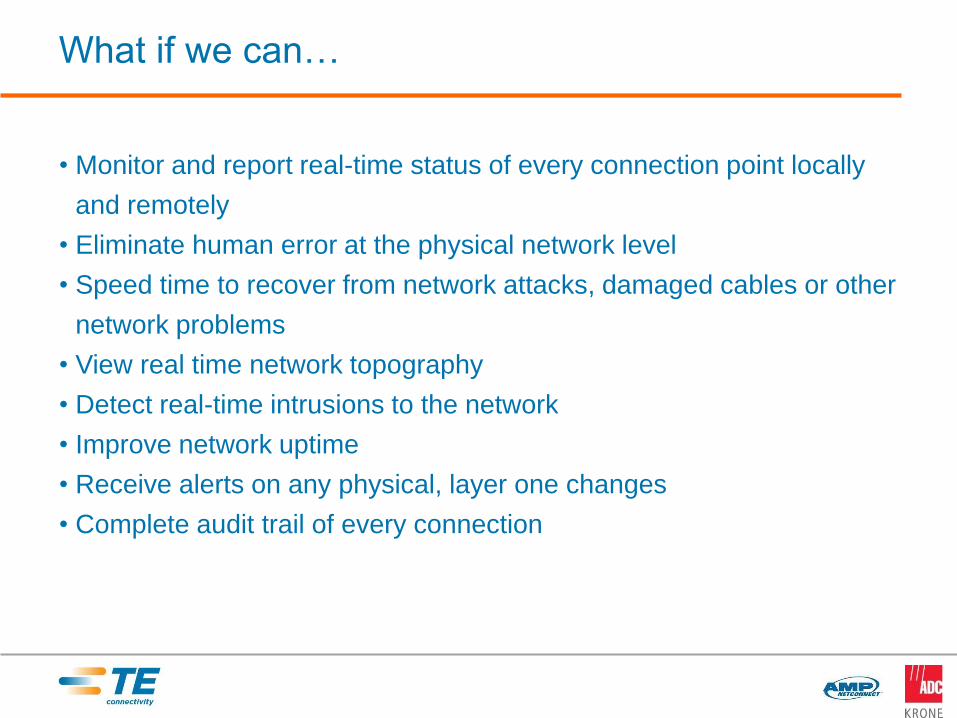
What if we can…
• Monitor and report real-time status of every connection point locally
and remotely
• Eliminate human error at the physical network level
• Speed time to recover from network attacks, damaged cables or other
network problems
• View real time network topography
• Detect real-time intrusions to the network
• Improve network uptime
• Receive alerts on any physical, layer one changes
• Complete audit trail of every connection


TE Connectivity is a Market Leader,
Not a Follower – Clear Your Minds to a New Way
21
QUAREO TECHNOLOGY
Information is Tyco Electronics
Confidential & Proprietary
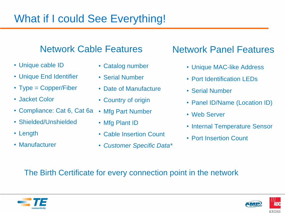
What if I could See Everything!
• Unique cable ID
• Unique End Identifier
• Type = Copper/Fiber
• Jacket Color
• Compliance: Cat 6, Cat 6a
• Shielded/Unshielded
• Length
• Manufacturer
• Catalog number
• Serial Number
• Date of Manufacture
• Country of origin
• Mfg Part Number
• Mfg Plant ID
• Cable Insertion Count
• Customer Specific Data*
• Unique MAC-like Address
• Port Identification LEDs
• Serial Number
• Panel ID/Name (Location ID)
• Web Server
• Internal Temperature Sensor
• Port Insertion Count
Network Cable Features Network Panel Features
The Birth Certificate for every connection point in the network

Managed Connectivity
December 2, 2014
Smart Connection Points
Quareo Technology
Ecosystem
Managed Connectivity What is it and what does it enable?
Application Partnerships Deliver Long-Term
Value
The heart of the TechnologyA unique ID applied to network connection points enables
the auto-discovery and mapping of all physical layer
connection points, making important information available
to upstream network management systems

What if I could Manage the Physical Layer the same as
Layers 2 through 7???
December 2, 2014
7
• Layer 7 - Application Layer6
• Layer 6 - Presentation Layer5
• Layer 5 - Session Layer4
• Layer 4 - Transport Layer3
• Layer 3 - Network Layer
2 • Layer 2 - Data Link Layer
1• Layer 1 - Physical Layer
Today: Network Management
solutions monitor, control and
secure
layers 2 through 7
The ability to query, view and
manage Layer 1 in a manner
that is integrated with current
network management policies
has not been possible until
now
Quareo enables standard
Network Management policies
to be applied to the physical
layer

7
• Layer 7 - Application Layer6
• Layer 6 - Presentation Layer5
• Layer 5 - Session Layer4
• Layer 4 - Transport Layer3
• Layer 3 - Network Layer
2 • Layer 2 - Data Link Layer
1 • Layer 1 - Physical Layer
Empowers network managers with
unprecedented levels of security and
manageability and breaks the barrier between L1 to L2
enabling new applications
2512/2/2014
What if I could Manage the Physical Layer the same as
Layers 2 through 7???
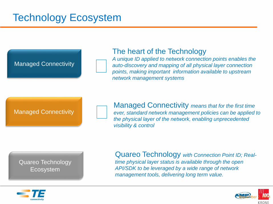
Technology Ecosystem
December 2, 2014
Managed Connectivity
Managed Connectivity
Quareo Technology
Ecosystem
The heart of the TechnologyA unique ID applied to network connection points enables the
auto-discovery and mapping of all physical layer connection
points, making important information available to upstream
network management systems
Managed Connectivity means that for the first time
ever, standard network management policies can be applied to
the physical layer of the network, enabling unprecedented
visibility & control
Quareo Technology with Connection Point ID; Real-
time physical layer status is available through the open
API/SDK to be leveraged by a wide range of network
management tools, delivering long term value.
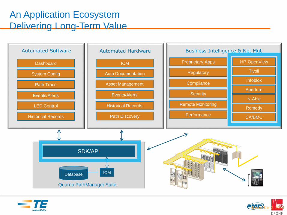
An Application Ecosystem
Delivering Long-Term Value
December 2, 2014
Quareo PathManager Suite
Database
SDK/API
ICM
Automated Software
Path Trace
LED Control
Events/Alerts
Historical Records
Dashboard
System Config
ICM
Automated Hardware
Auto Documentation
Asset Management
Historical Records
Events/Alerts
Business Intelligence & Net Mgt
Proprietary Apps
Regulatory
Compliance
Security
Remote Monitoring
Performance
HP OpenView
Tivoli
Infoblox
Aperture
N-Able
Remedy
CA/BMCPath Discovery
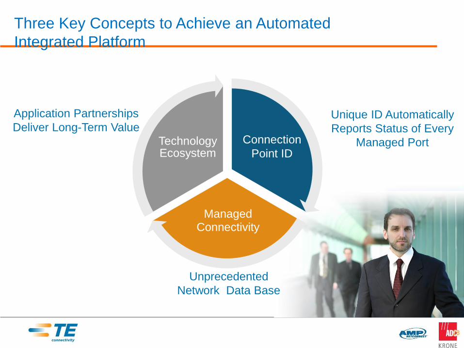
Three Key Concepts to Achieve an Automated
Integrated Platform
28
Application Partnerships
Deliver Long-Term Value
Unprecedented
Network Data Base
Managed Connectivity
Technology Ecosystem
Unique ID Automatically
Reports Status of Every
Managed PortConnection
Point ID
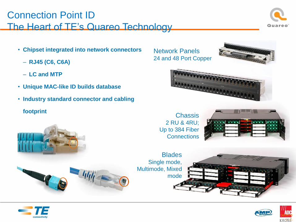
Connection Point ID
The Heart of TE’s Quareo Technology
• Chipset integrated into network connectors
– RJ45 (C6, C6A)
– LC and MTP
• Unique MAC-like ID builds database
• Industry standard connector and cabling
footprint
Decemb
er 2,
2014
Network Panels24 and 48 Port Copper
Chassis2 RU & 4RU;
Up to 384 Fiber
Connections
BladesSingle mode,
Multimode, Mixed
mode

Our Capabilities that Set Us Apart • CPID
• ICM
– CPID is nothing without the ICM Industry Leading Software!
• Asset Tree
• Floor Plan Integration
• Rack Front View
• Drag and Drop Environment
• Ability to Manage Generic Assets
• Work Flow and Work Order Tracking
• Automatic Connection Detection
• Highest Level of Security
• Low and High Level Reporting
• Multiple User Access Levels
• Web Access
page 30
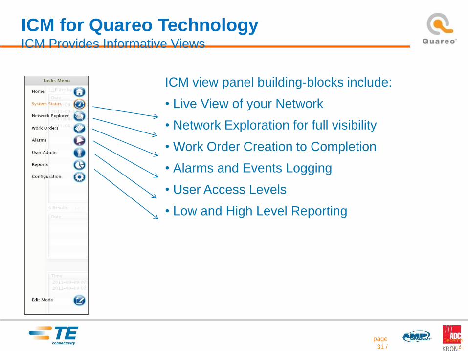
ICM view panel building-blocks include:
• Live View of your Network
• Network Exploration for full visibility
• Work Order Creation to Completion
• Alarms and Events Logging
• User Access Levels
• Low and High Level Reporting
ICM for Quareo Technology ICM Provides Informative Views
Decemb
er 2,
2014
page
31 /

ICM for Quareo Technology Asset Tree building
Decemb
er 2,
2014
page
32 /
Quareo Assets
Discovered Automatically
Drag and Drop Asset tree view

ICM for Quareo Technology Asset Details
Decemb
er 2,
2014
page
33 /

ICM for Quareo Technology Floor Plan Integration
Decemb
er 2,
2014
page
34 /

ICM for Quareo Technology Equipment Front View
Decemb
er 2,
2014
page
35 /

How Integration creates a smarter more secure network
page 36
100%
Work Order Placed
Work Order Closed
Circuit Trace updated in
ICM AutomaticallySwitch Field Server Field
ICM
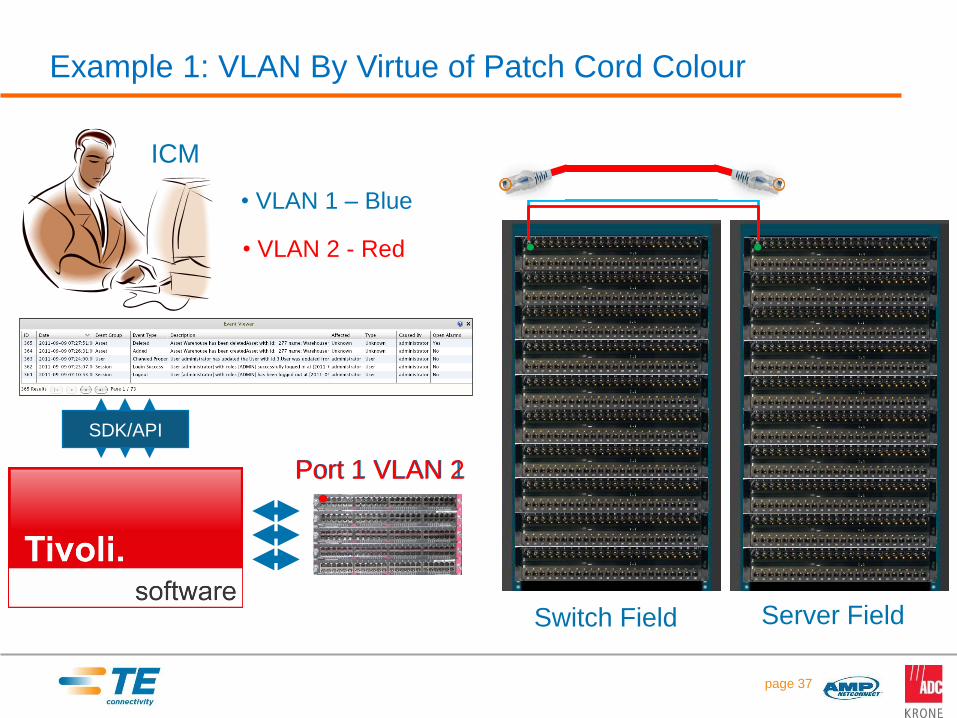
Example 1: VLAN By Virtue of Patch Cord Colour
page 37
Switch Field Server Field
ICM
• VLAN 1 – Blue
• VLAN 2 - Red
SDK/API
Port 1 VLAN 1Port 1 VLAN 2
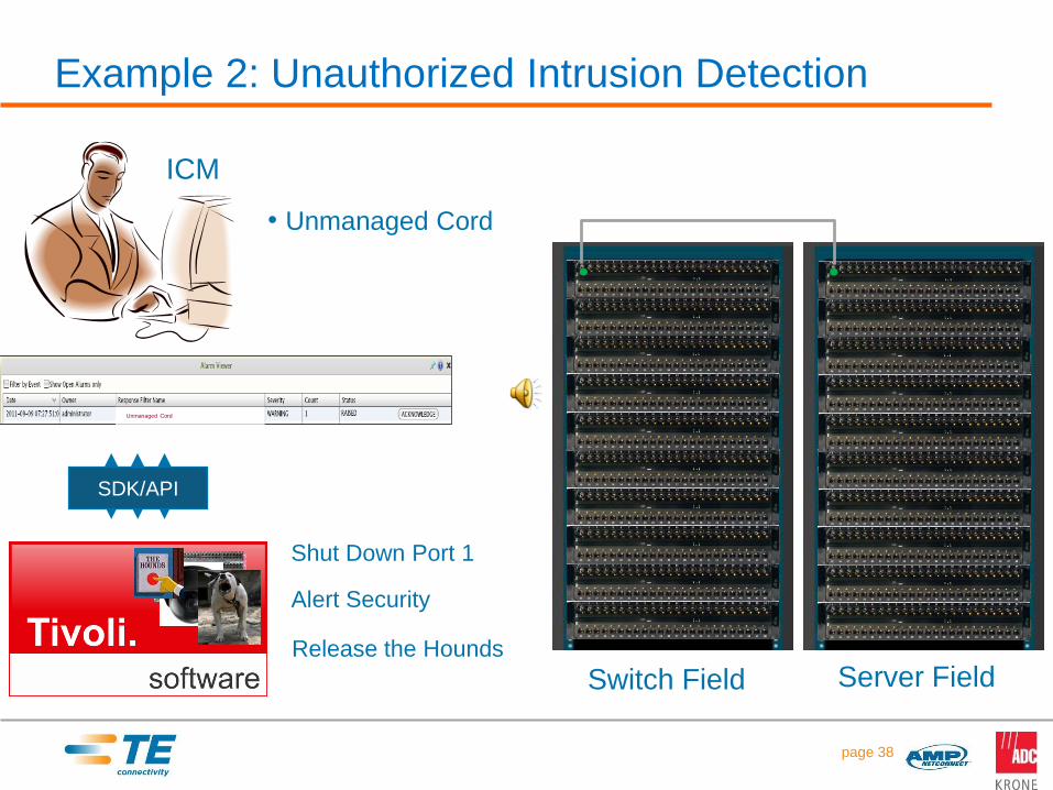
Example 2: Unauthorized Intrusion Detection
page 38
Switch Field Server Field
ICM
SDK/API
Shut Down Port 1
• Unmanaged Cord
Alert Security
Release the Hounds
Unmanaged Cord
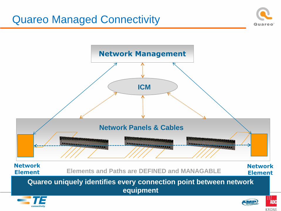
Network Panels & Cables
ICM
Quareo Managed Connectivity
Quareo uniquely identifies every connection point between network
equipment
Network Management
NetworkElement
NetworkElement Elements and Paths are DEFINED and MANAGABLE
date/time
Thank you!


