BA237F/00/en/08.06
52010990
Valid as of software version:
V 01.04.00 (amplifier)
V 01.04.00 (communication)
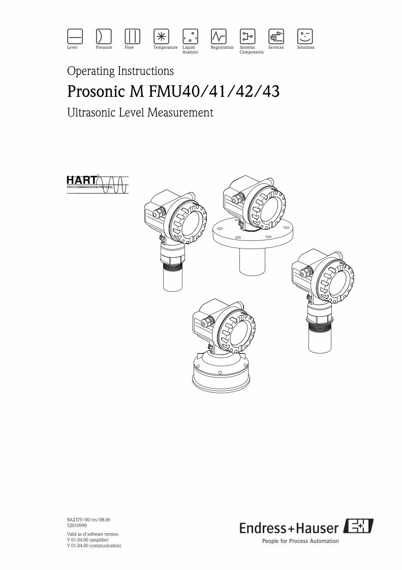
Operating Instructions
Prosonic M FMU40/41/42/43Ultrasonic Level Measurement
6

Short instructions
2
Short instructions
L00-FMU4xxx-05-00-00-en-001
Contents of the operating instructions
This operating instructions describes the installation and commissioning of the Prosonic M
ultrasonic level transmitter. It contains all the functions required for a normal measuring operation.
Also, the Prosonic M provides additional functions for optimising the measuring point and for
converting the measured value. These functions are not included in this operating instructions.
You can find an overview of all the device functions in the Appendix.
You can find a detailed description of all the device functions in the operating instructions BA
240F/00/en "Prosonic M - Description of Instrument Functions". This is located on the supplied
documentation CD-ROM.
E+-
+
E+-
F
L
D
E
E
E
-
… …
KA 183F/00/a2/02.0252010993
BD
… …
100%
0%
100 (HART)2457 (PA,FF)
333 (HART)33333 (PA,FF)
… …
52010993
… …
Prosonic M - Quick Setup
- domeceiling
- horizontalcyl.
- bypass…
- unknown- liquid- > 4 mm- < 4 mm
- standard- calm
surface- add.
agitator…
input E(s. sketch)
input F(s. sketch)
- ok- too small- too big- unknown- manual
displayed(s. sketch)
D and L are confirm
or specifyrange
suggestion
000measured value
Groupselection
00basic setup
01safety settings
0Csystemparameter
0EEnvelope curve
04linearisation
05extended calibr.
06output (HART, FF)profibus param.(PA)
0Adiagnostics
0A0presenterror
002tank shape
004processcond.
005emptycalibr.
006fullcalibr.
008dist./meas value
051checkdistance
003mediumproperty
052range ofmapping
053startmapping
008dist./meas value
0E1plot settings
0E2recordingcurve
0A1previouserror
0A4unlockparameter
0Etemperature
09display
092language
BD: blocking distance
0A3reset
0C0tag no.
059blockingdistance
Bdisplayed(s. sketch)
D is
Contrast: + or +
Table of contents
3
Table of contents
1 Safety instructions . . . . . . . . . . . . . . . . 4
1.1 Designated use . . . . . . . . . . . . . . . . . . . . . . . . . . . . 4
1.2 Installation, commissioning, operation . . . . . . . . . . . 4
1.3 Hazardous area . . . . . . . . . . . . . . . . . . . . . . . . . . . . 4
1.4 Notes on safety conventions and symbols . . . . . . . . . 5
2 Identification . . . . . . . . . . . . . . . . . . . . 6
2.1 Nameplate . . . . . . . . . . . . . . . . . . . . . . . . . . . . . . . 6
2.2 Product structure FMU 40 . . . . . . . . . . . . . . . . . . . . 7
2.3 Product structure FMU 41 . . . . . . . . . . . . . . . . . . . . 8
2.4 Product structure FMU 42 . . . . . . . . . . . . . . . . . . . . 9
2.5 Product structure FMU 43 . . . . . . . . . . . . . . . . . . . 10
2.6 Scope of delivery . . . . . . . . . . . . . . . . . . . . . . . . . . 11
2.7 Certificates and approvals . . . . . . . . . . . . . . . . . . . 11
2.8 Registered trademarks . . . . . . . . . . . . . . . . . . . . . . 11
3 Installation . . . . . . . . . . . . . . . . . . . . . 12
3.1 Dimensions . . . . . . . . . . . . . . . . . . . . . . . . . . . . . . 12
3.2 Installation variants . . . . . . . . . . . . . . . . . . . . . . . . 13
3.3 Installation conditions . . . . . . . . . . . . . . . . . . . . . . 15
3.4 Measuring range . . . . . . . . . . . . . . . . . . . . . . . . . . 18
3.5 Installation hint for FMU 40/41 . . . . . . . . . . . . . . 20
3.6 Turn housing . . . . . . . . . . . . . . . . . . . . . . . . . . . . . 20
3.7 Installation check . . . . . . . . . . . . . . . . . . . . . . . . . 20
4 Wiring . . . . . . . . . . . . . . . . . . . . . . . . 21
4.1 Electrical connection . . . . . . . . . . . . . . . . . . . . . . . 21
4.2 Terminal assignment . . . . . . . . . . . . . . . . . . . . . . . 22
4.3 Supply voltage . . . . . . . . . . . . . . . . . . . . . . . . . . . . 23
4.4 Potential matching . . . . . . . . . . . . . . . . . . . . . . . . 24
4.5 Checking the connection . . . . . . . . . . . . . . . . . . . . 24
5 Operation . . . . . . . . . . . . . . . . . . . . . . 25
5.1 Display and operating elements . . . . . . . . . . . . . . . 25
5.2 Function codes . . . . . . . . . . . . . . . . . . . . . . . . . . . 27
5.3 Operating options . . . . . . . . . . . . . . . . . . . . . . . . . 28
5.4 Operation using the on-site display VU 331 . . . . . . 29
5.5 Operation using ToF Tool . . . . . . . . . . . . . . . . . . . 30
5.6 Operation with Commuwin II . . . . . . . . . . . . . . . . 32
5.7 Operation using a HART handheld terminal DXR 375
32
5.8 Lock/unlock configuration . . . . . . . . . . . . . . . . . . 33
5.9 Resetting the customer parameters . . . . . . . . . . . . . 33
5.10 Resetting an interference echo suppression (tank map)
34
6 Commissioning. . . . . . . . . . . . . . . . . . 35
6.1 Power up instrument . . . . . . . . . . . . . . . . . . . . . . . 35
6.2 Basic calibration . . . . . . . . . . . . . . . . . . . . . . . . . . 36
6.3 Envelope curve . . . . . . . . . . . . . . . . . . . . . . . . . . . 42
7 Troubleshooting . . . . . . . . . . . . . . . . . 45
7.1 System error messages . . . . . . . . . . . . . . . . . . . . . . 45
7.2 Application errors . . . . . . . . . . . . . . . . . . . . . . . . . 47
8 Maintenance and repairs . . . . . . . . . . . 49
8.1 Exterior cleaning . . . . . . . . . . . . . . . . . . . . . . . . . . 49
8.2 Repairs . . . . . . . . . . . . . . . . . . . . . . . . . . . . . . . . . 49
8.3 Repairs to Ex-approved devices . . . . . . . . . . . . . . . 49
8.4 Replacement . . . . . . . . . . . . . . . . . . . . . . . . . . . . . 49
8.5 Spare parts (housing type F12) . . . . . . . . . . . . . . . . 50
8.6 Spare parts (housing type T12) . . . . . . . . . . . . . . . . 53
8.7 Return . . . . . . . . . . . . . . . . . . . . . . . . . . . . . . . . . . 56
8.8 Disposal . . . . . . . . . . . . . . . . . . . . . . . . . . . . . . . . . 56
8.9 Software history . . . . . . . . . . . . . . . . . . . . . . . . . . . 56
8.10 Contact addresses of Endress+Hauser . . . . . . . . . . . 56
9 Accessories . . . . . . . . . . . . . . . . . . . . . 57
9.1 Weather protection cover . . . . . . . . . . . . . . . . . . . . 57
9.2 Installation bracket for FMU 40/41 . . . . . . . . . . . . 57
9.3 Adapter flange . . . . . . . . . . . . . . . . . . . . . . . . . . . . 58
9.4 Cantilever . . . . . . . . . . . . . . . . . . . . . . . . . . . . . . . 59
9.5 Mounting Frame . . . . . . . . . . . . . . . . . . . . . . . . . . 60
9.6 Wall Bracket . . . . . . . . . . . . . . . . . . . . . . . . . . . . . 60
9.7 Mounting bracket for FMU 43 . . . . . . . . . . . . . . . . 61
9.8 Commubox FXA191 HART . . . . . . . . . . . . . . . . . . 61
9.9 Commubox FXA195 HART . . . . . . . . . . . . . . . . . . 61
9.10 Commubox FXA291 . . . . . . . . . . . . . . . . . . . . . . . 61
9.11 ToF Adapter FXA291 . . . . . . . . . . . . . . . . . . . . . . . 62
9.12 Remote display FHX40 . . . . . . . . . . . . . . . . . . . . . . 63
10 Technical Data. . . . . . . . . . . . . . . . . . . 64
10.1 Technical data at a glance . . . . . . . . . . . . . . . . . . . 64
11 Appendix. . . . . . . . . . . . . . . . . . . . . . . 68
11.1 Operating menu . . . . . . . . . . . . . . . . . . . . . . . . . . 68
11.2 Measuring principle . . . . . . . . . . . . . . . . . . . . . . . . 70
Index . . . . . . . . . . . . . . . . . . . . . . . . . . . . . . 71
Safety instructions
4
1 Safety instructions
1.1 Designated use
The Prosonic M is a compact measuring device for continuous, non-contact level measurement.
Depending on the sensor, the measuring range is up to 15m in fluids and up to 7m in bulk solids.
By using the linearisation function, the Prosonic M can also be used for flow measurements in open
channels and measuring weirs.
1.2 Installation, commissioning, operation
The Prosonic M is fail-safe and is constructed to the state-of-the-art. It meets the appropriate
standards and EC directives. However, if you use it improperly or other than for its designated use,
it may pose application-specific hazards, e.g. product overflow due to incorrect installation or
configuration. Installation, electrical connection, start-up, operation and maintenance of the
measuring device must therefore be carried out exclusively by trained specialists authorised by the
system operator. Technical personnel must have read and understood these operating instructions
and must adhere to them. You may only undertake modifications or repair work to the device when
it is expressly permitted by the operating instructions.
1.3 Hazardous area
Measuring systems for use in hazardous environments are accompanied by separate "Ex
documentation", which is an integral part of this Operating Manual. Strict compliance with the
installation instructions and ratings as stated in this supplementary documentation is mandatory.
• Ensure that all personnel are suitably qualified.
• Observe the specifications in the certificate as well as national and local standards and regulations.

Safety instructions
5
1.4 Notes on safety conventions and symbols
In order to highlight safety-relevant or alternative operating procedures in the manual, the following
conventions have been used, each indicated by a corresponding symbol in the margin.
Safety conventions
#Warning!
A warning highlights actions or procedures which, if not performed correctly, will lead to personal
injury, a safety hazard or destruction of the instrument
"Caution!
Caution highlights actions or procedures which, if not performed correctly, may lead to personal
injury or incorrect functioning of the instrument
!Note!
A note highlights actions or procedures which, if not performed correctly, may indirectly affect
operation or may lead to an instrument response which is not planned
Explosion protection
0Device certified for use in explosion hazardous area
If the device has this symbol embossed on its name plate it can be installed in an explosion hazardous
area
-Explosion hazardous area
Symbol used in drawings to indicate explosion hazardous areas. Devices located in and wiring
entering areas with the designation “explosion hazardous areas” must conform with the stated type
of protection.
.Safe area (non-explosion hazardous area)
Symbol used in drawings to indicate, if necessary, non-explosion hazardous areas. Devices located in
safe areas still require a certificate if their outputs run into explosion hazardous areas
Electrical symbols
% Direct voltage
A terminal to which or from which a direct current or voltage may be applied or supplied
&Alternating voltage
A terminal to which or from which an alternating (sine-wave) current or voltage may be applied or
supplied
)Grounded terminal
A grounded terminal, which as far as the operator is concerned, is already grounded by means of an
earth grounding system
*Protective grounding (earth) terminal
A terminal which must be connected to earth ground prior to making any other connection to the
equipment
+Equipotential connection (earth bonding)
A connection made to the plant grounding system which may be of type e.g. neutral star or
equipotential line according to national or company practice
Temperature resistance of the connection cables
States, that the connection cables must be resistant to a temperature of at least 85 °C.t >85°C
Identification
6
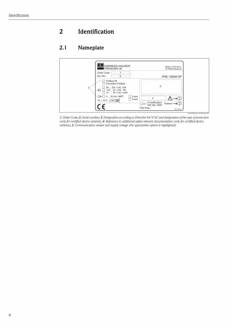
2 Identification
2.1 Nameplate
L00-FMU4xxxx-18-00-00-yy-001
1: Order Code; 2: Serial number; 3: Designation according to Directive 94/9/EC and designation of the type of protection
(only for certified device variants); 4: Reference to additional safety-relevant documentation (only for certified device
variants); 5: Communication variant and supply voltage (the appropriate option is highlighted)
Made in GermanyD-79689 Maulburg
Dat./Insp.:
Order Code:
IP68 / NEMA 6PSer.-No.:
90 … 253 V AC 4VA10,5 …32 V DC 1W14 … 36 V DC 0,8W
4 … 20 mA HART 2-wire4-wire
Profibus PAFoundation Fieldbus
ENDRESS+HAUSER
t >85°CTA > 70°C :
D01345-B
if modificationsee sep. labelX = Patents
PROSONIC-M
1
2
3
4
5

Identification
7
2.2 Product structure FMU 40
Certificates
A Variant for non-hazardous area
1 ATEX II 1/2 G or II 2 G; EEX ia IIC T6
4 ATEX II 1/2 G or II 2 G; EEX d [ia] IIC T6
G ATEX II 3G EEx nA II T6
2 ATEX II 1/2D, Alu blind cover
5 ATEX II 1/3D
S FM IS Cl. I,II,III Div. 1 Gr. A-G / NI Cl. I Div. 2
T FM XP Cl. I,II,III Div. 1 Gr. A-G
U CSA IS Cl. I,II,III Div. 1 Gr. A-G / NI Cl. I Div. 2
V CSA XP Cl. I,II,III Div. 1 Gr. A-G
N CSA General Purpose
K TIIS Ex ia II C T6
Y Special certificate
Process connection
R G 1½“ threadISO 228
N NPT 1½“ - 11,5 thread
Y Special version
Power supply/communication
B 2 wire, 4...20mA-loop/HART
H 4 wire, 10,5...32VDC / 4-20mA HART
G 4 wire, 90...253VAC / 4-20mA HART
D 2 wire, PROFIBUS PA
F 2 wire, Foundation Fieldbus
Y Special version
Display / on-site operation
1 Without LC display
2 With LC display VU 331 incl. on-site operation
3 Prepared for remote display FHX 40
9 Special version
Housing
A Aluminium F12 housing coated to IP 68
C Aluminium T12 housing coated to IP 68; with separate terminal compartment
D Aluminium T12 housing coated to IP 68; with separate terminal compartment;
with overvoltage protection
9 Special version
Screw union/entry
2 M20x1.5 screw union
3 G 1/2“ entry
4 NPT 1/2“ entry
5 M12 PROFIBUS-PA plug-in connector
6 7/8" FF plug
9 Special version
FMU 40 - Product designation
Identification
8
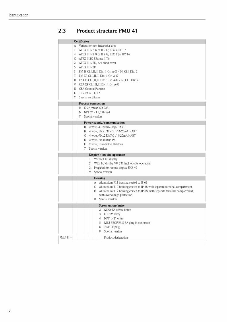
2.3 Product structure FMU 41
Certificates
A Variant for non-hazardous area
1 ATEX II 1/2 G or II 2 G; EEX ia IIC T6
4 ATEX II 1/2 G or II 2 G; EEX d [ia] IIC T6
G ATEX II 3G EEx nA II T6
2 ATEX II 1/2D, Alu blind cover
5 ATEX II 1/3D
S FM IS Cl. I,II,III Div. 1 Gr. A-G / NI Cl. I Div. 2
T FM XP Cl. I,II,III Div. 1 Gr. A-G
U CSA IS Cl. I,II,III Div. 1 Gr. A-G / NI Cl. I Div. 2
V CSA XP Cl. I,II,III Div. 1 Gr. A-G
N CSA General Purpose
K TIIS Ex ia II C T6
Y Special certificate
Process connection
R G 2“ threadISO 228
N NPT 2“ - 11,5 thread
Y Special version
Power supply/communication
B 2 wire, 4...20mA-loop/HART
H 4 wire, 10,5...32VDC / 4-20mA HART
G 4 wire, 90...253VAC / 4-20mA HART
D 2 wire, PROFIBUS PA
F 2 wire, Foundation Fieldbus
Y Special version
Display / on-site operation
1 Without LC display
2 With LC display VU 331 incl. on-site operation
3 Prepared for remote display FHX 40
9 Special version
Housing
A Aluminium F12 housing coated to IP 68
C Aluminium T12 housing coated to IP 68 with separate terminal compartment
D Aluminium T12 housing coated to IP 68; with separate terminal compartment;
with overvoltage protection
9 Special version
Screw union/entry
2 M20x1.5 screw union
3 G 1/2“ entry
4 NPT 1/2“ entry
5 M12 PROFIBUS-PA plug-in connector
6 7/8" FF plug
9 Special version
FMU 41 - Product designation

Identification
9
2.4 Product structure FMU 42
Certificates
A Variant for non-hazardous area
1 ATEX II 1/2 G EEX ia IIC T6
4 ATEX II 1/2 G EEX d [ia] IIC T6
G ATEX II 3G EEx nA II T6 (in preparation)
S FM IS Cl. I,II,III Div. 1 Gr. A-G / NI Cl. I Div. 2
T FM XP Cl. I,II,III Div. 1 Gr. A-G
U CSA IS Cl. I,II,III Div. 1 Gr. A-G / NI Cl. I Div. 2
V CSA XP Cl. I,II,III Div. 1 Gr. A-G
N CSA General Purpose
K TIIS Ex ia II C T6 (in preparation)
Y Special certificate
Process connection
M mounting bracket FAU20
P DN80/ANSI 3"/JIS10K80, PP, Universal flange
Q DN80/ANSI 3"/JIS10K80, PVDF, Universal flange
S DN80/ANSI 3"/JIS10K80, 316L, Universal flange
T DN100/ANSI 4"/JIS16K100, PP, Universal flange
U DN100/ANSI 4"/JIS16K100, PVDF, Universal flange
V DN100/ANSI 4"/JIS16K100, 316L, Universal flange
Y Special version
Power supply/communication
B 2 wire, 4...20mA-loop/HART
H 4 wire, 10,5...32VDC / 4-20mA HART
G 4 wire, 90...253VAC / 4-20mA HART
D 2 wire, PROFIBUS PA
F 2 wire, Foundation Fieldbus
Y Special version
Display / on-site operation
1 Without LC display
2 With LC display VU 331 incl. on-site operation
3 Prepared for remote display FHX 40
9 Special version
Housing
A Aluminium F12 housing coated to IP 68
C Aluminium T12 housing coated to IP 68, with separate terminal compartment
D Aluminium T 12 housing coated to IP 68, with separate terminal compartment; with
overvoltage protection
Y Special version
Gland/Entry
2 M20x1.5 gland
3 G 1/2“ entry
4 NPT 1/2“ entry
5 M12 PROFIBUS-PA plug
6 7/8" FF plug
9 Special version
Sealing Sensor/Flange
2 VITON flat sealing
3 EPDM flat sealing
9 special version
Additional options
A Additional options not selected
FMU 42 - Product designation

Identification
10
2.5 Product structure FMU 43
Certificates
A Variant for non-hazardous area
2 ATEX II 1/2 D or II 2 D, Aluminium Deckel
5 ATEX II 1/3 D or II 3 D, Sichtdeckel
M FM DIP Class II, III, Div. 1, Gr. E,F,G NI
N CSA General Purpose
P CSA DIP, Class II, III, Div. 1, Gr. E,F,G NI
Y Special version
Process connection/material
P Flange DN 100/ANSI 4"/JIS 16K100, PP (universal slip-on flange included)
S Flange DN 100/ANSI 4"/JIS 16K100, SS 316TI (universal slip-on flange included)
K Without slip-on flange/without mounting bracket (customer mounting equipment)
M With mounting bracket
Y Special version
Power supply/communication
H 4 wire, 10,5...32VDC / 4-20mA HART
G 4 wire, 90...253VAC / 4-20mA HART
D 2 wire, PROFIBUS PA
F 2 wire, Foundation Fieldbus
Y Special version
Display / on-site operation
1 Without LC display
2 With LC display VU 331 incl. on-site operation
3 Prepared for remote display FHX 40
9 Special version
Housing
A Aluminium F12 housing coated to IP 68
9 Special version
Screw union/entry
2 M20x1.5 screw union
3 G 1/2“ entry
4 NPT 1/2“ entry
5 M12 PROFIBUS-PA plug-in connector
6 7/8" FF plug
9 Special version
FMU 43 - Product designation
Identification
11
2.6 Scope of delivery
2.6.1 Instrument and accessories
• Instrument according to the version ordered
• "ToF Tool - FieldTool Package" (2 CD-ROMs)
• for FMU 40/41 in the versions FMU 40 *R**** and FMU 41 *R****: counter nut (PC)
• for FMU 40/41: sealing ring (EPDM)
• for gland M20x1.5:
– 1 cable gland for 2-wire instruments
– 2 cable glands for 4-wire instruments
The cable glands are mounted on delivery.
2.6.2 Supplied documentation
Short instructions (KA 183F, in the instrument)
intended as a memory jogger for users who are familiar with the operating concept of
Endress+Hauser Time-of-Flight instruments.
Operating instructions (BA 237F, this booklet)
This describes the installation and commissioning of the Prosonic M. The operating menu includes
all the functions which are required for standard measurement tasks. Any additional functions are
not included.
Description of Instrument Functions (BA 240F)
contains a detailed description of all the functions of the Prosonic M. You can find this document
as a pdf file on the supplied ToF Tool - FieldTool CD-ROM 1.
Safety instructions
Additional safety instructions (XA, ZE, ZD) are supplied with certified device versions. Refer to the
nameplate for the names of the safety instructions that apply to your device version.
2.7 Certificates and approvals
CE mark, declaration of conformity
The device is designed to meet state-of-the-art safety requirements, has been tested and left the
factory in a condition in which it is safe to operate. The device complies with the applicable
standards and regulations as listed in the EC declaration of conformity and thus complies with the
statutory requirements of the EG directives. Endress+Hauser confirms the successful testing of the
device by affixing to it the CE mark.
2.8 Registered trademarks
HART®
Registered trademark of HART Communication Foundation, Austin, USA
ToF®
Registered trademark of the company Endress+Hauser GmbH+Co. KG, Maulburg, Germany
PulseMaster®
Registered trademark of the company Endress+Hauser GmbH+Co. KG, Maulburg, Germany
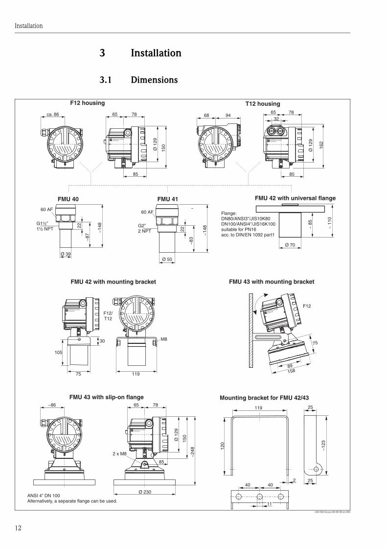
Installation
12
3 Installation
3.1 Dimensions
L00-FMU4xxxx-06-00-00-en-003
65 78
Ø 1
29
ca. 86 78
8585
65
Ø 1
29
162
150
68 94
~14
8
~83
22
FMU 40 FMU 41
Ø 39Ø 50
~14
8
~87
22
85
2 x M8
65 78
Ø 1
29
~86
150
~24
8
11
119
2
25
120
~12
3
25
ENDRESS+HAUSERProsonic M ENDRESS+HAUSER
Prosonic M
ENDRESS+HAUSERProsonic M
ENDRESS+HAUSER
Prosonic M
40 40
32
158
Ø 230
~ 1
10
Ø 70
ENDRESS+HAUSERProsonic M
F12/T12
75
30
119
M8
F12
105
75
~ 8
5
89
F12 housing T12 housing
FMU 43 with slip-on flange
FMU 43 with mounting bracket
60 AF
G2”2 NPT
G1½”1½ NPT
60 AF
ANSI 4” DN 100Alternatively, a separate flange can be used.
Mounting bracket for FMU 42/43
FMU 42 with universal flange
Flange:DN80/ANSI3"/JIS10K80DN100/ANSI4"/JIS16K100suitable for PN16acc. to DIN/EN 1092 part1
FMU 42 with mounting bracket
Installation
13
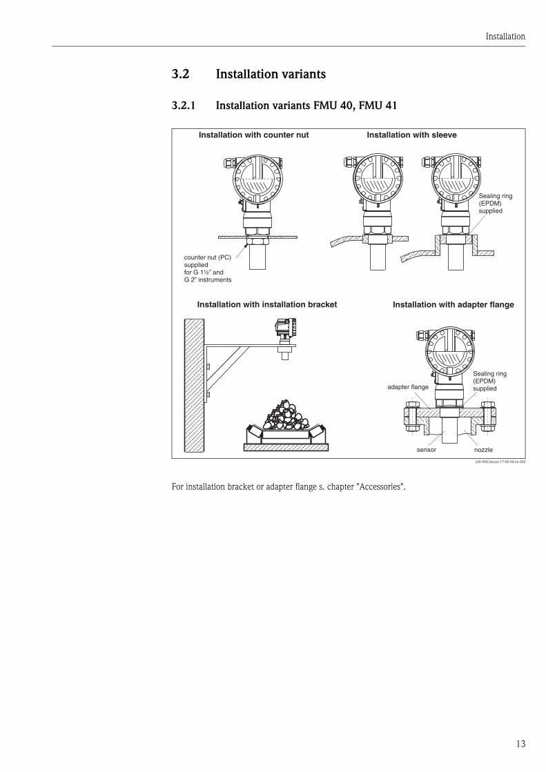
3.2 Installation variants
3.2.1 Installation variants FMU 40, FMU 41
L00-FMU4xxxx-17-00-00-en-002
For installation bracket or adapter flange s. chapter "Accessories".
ENDRESS+HAUSERProsonic M
Installation with sleeveInstallation with counter nut
Installation with installation bracket
counter nut (PC)suppliedfor G 1½” andG 2” instruments
adapter flange
sensor nozzle
Sealing ring(EPDM)supplied
Installation with adapter flange
Sealing ring(EPDM)supplied
Installation
14
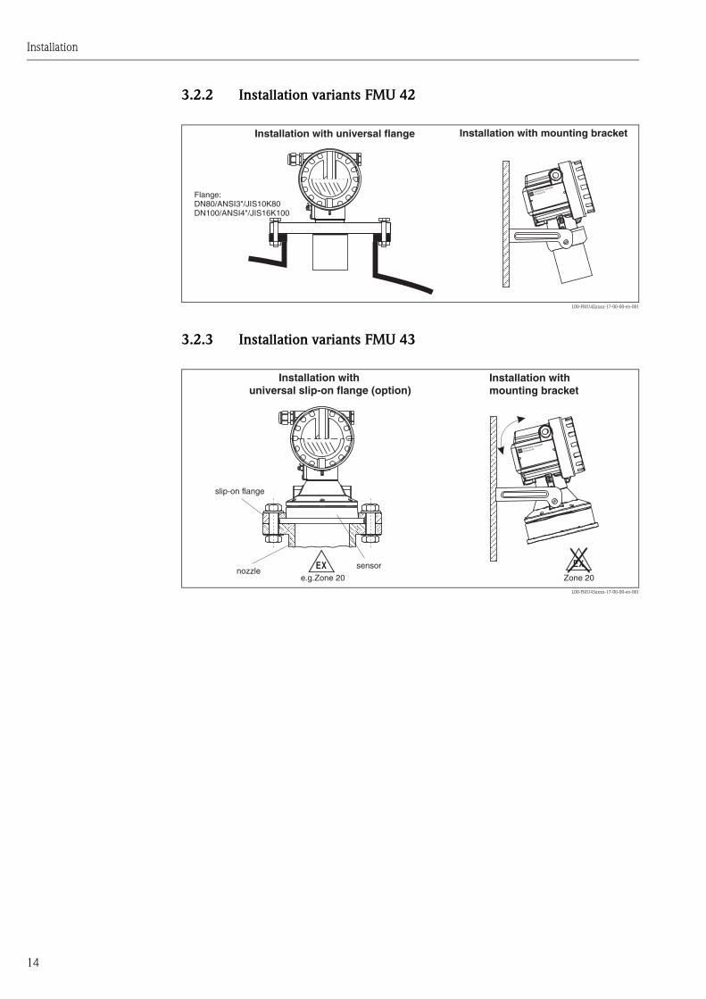
3.2.2 Installation variants FMU 42
L00-FMU42xxxx-17-00-00-en-001
3.2.3 Installation variants FMU 43
L00-FMU43xxxx-17-00-00-en-001
ENDRESS+HAUSER
Prosonic M
Installation with universal flange
Flange:DN80/ANSI3"/JIS10K80DN100/ANSI4"/JIS16K100
Installation with mounting bracket
ENDRESS+HAUSER
Prosonic M
- .Zone 20
Installation withmounting bracket
Installation withuniversal slip-on flange (option)
slip-on flange
sensornozzle
e.g.Zone 20
Installation
15
3.3 Installation conditions
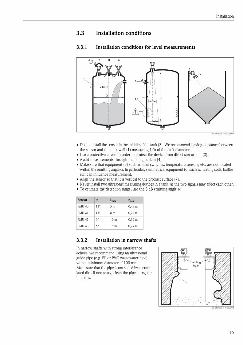
3.3.1 Installation conditions for level measurements
L00-FMU4xxxx-17-00-00-de-005
• Do not install the sensor in the middle of the tank (3). We recommend leaving a distance between
the sensor and the tank wall (1) measuring 1/6 of the tank diameter.
• Use a protective cover, in order to protect the device from direct sun or rain (2).
• Avoid measurements through the filling curtain (4).
• Make sure that equipment (5) such as limit switches, temperature sensors, etc. are not located
within the emitting angle α. In particular, symmetrical equipment (6) such as heating coils, baffles
etc. can influence measurement.
• Align the sensor so that it is vertical to the product surface (7).
• Never install two ultrasonic measuring devices in a tank, as the two signals may affect each other.
• To estimate the detection range, use the 3 dB emitting angle α.
3.3.2 Installation in narrow shafts
1
2 3 4
5
6
1/6D
7
D
r
α L
Sensor α Lmax rmax
FMU 40 11° 5 m 0,48 m
FMU 41 11° 8 m 0,77 m
FMU 42 9° 10 m 0,96 m
FMU 43 6° 15 m 0,79 m
In narrow shafts with strong interference
echoes, we recommend using an ultrasound
guide pipe (e.g. PE or PVC wastewater pipe)
with a minimum diameter of 100 mm.
Make sure that the pipe is not soiled by accumu-
lated dirt. If necessary, clean the pipe at regular
intervals.
L00-FMU4xxxx-17-00-00-en-010
ENDRESS+HAUSERProsonic MENDRESS+HAUSERProsonic M
ENDRESS+HAUSERProsonic MENDRESS+HAUSERProsonic M
ventinghole
Installation
16
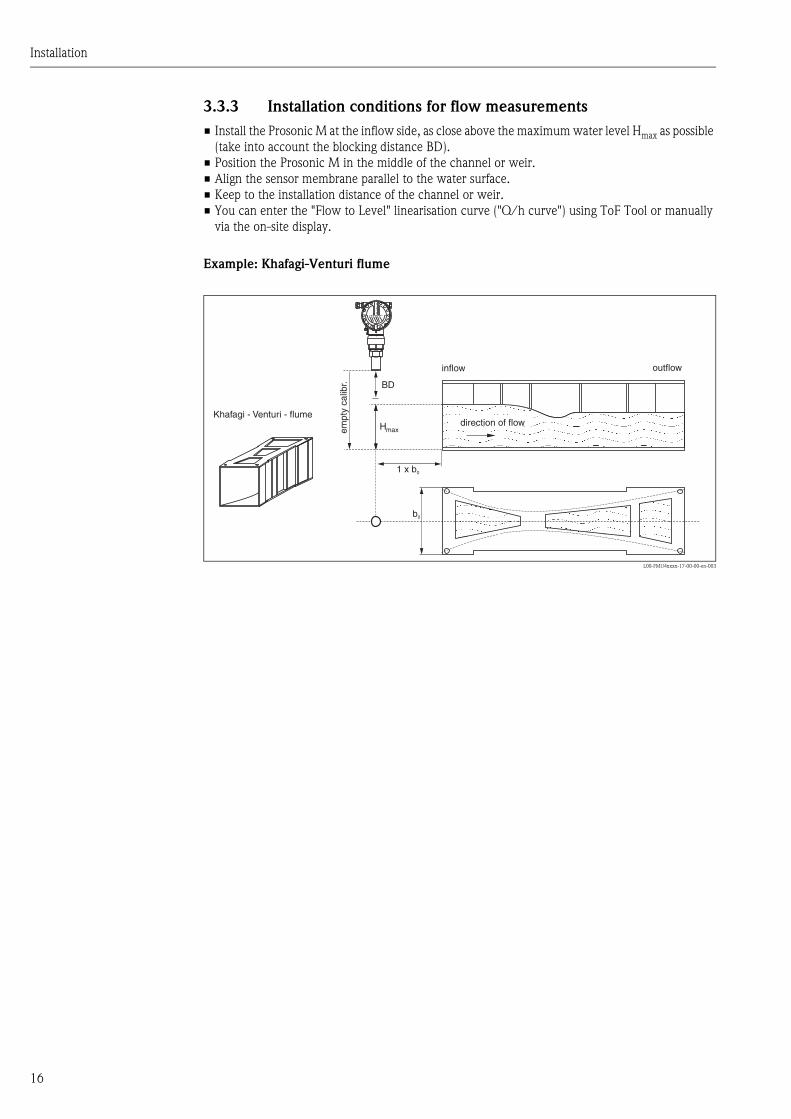
3.3.3 Installation conditions for flow measurements
• Install the Prosonic M at the inflow side, as close above the maximum water level Hmax as possible
(take into account the blocking distance BD).
• Position the Prosonic M in the middle of the channel or weir.
• Align the sensor membrane parallel to the water surface.
• Keep to the installation distance of the channel or weir.
• You can enter the "Flow to Level" linearisation curve ("Q/h curve") using ToF Tool or manually
via the on-site display.
Example: Khafagi-Venturi flume
L00-FMU4xxxx-17-00-00-en-003
1 x b0
b0
BD
Hmax
Khafagi - Venturi - flumedirection of flow
inflow outflow
empt
y ca
libr.
Installation
17
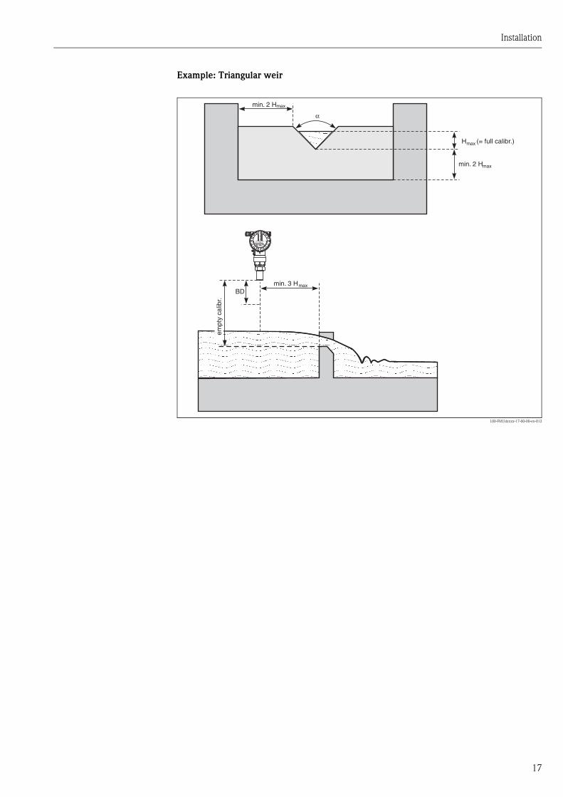
Example: Triangular weir
L00-FMU4xxxx-17-00-00-en-012
max
max
max
max
empt
y ca
libr.
(= full calibr.)
min. 3 H
H
min. 2 H
α
min. 2 H
BD

Installation
18
3.4 Measuring range
3.4.1 Blocking distance, Nozzle mounting
Install the Prosonic M at a height so that the blocking distance BD is not undershot, even at
maximum fill level. Use a pipe nozzle if you cannot maintain the blocking distance in any other way.
The interior of the nozzle must be smooth and may not contain any edges or welded joints. In
particular, there should be no burr on the inside of the tank side nozzle end. Note the specified limits
for nozzle diameter and length. To minimise disturbing factors, we recommend an angled socket
edge (ideally 45°).
L00-FMU4xxxx-17-00-00-en-004
BD: blocking distance; SD: safety distance; E: empty calibration; F: full calibration (span); D: nozzle diameter; L: nozzle
length
" Caution!
If the blocking distance is undershot, it may cause device malfunction.
FE
BDSD
L
D
FMU 40/41
L
D
FMU 43
L
D
FMU 42
Sensor BDMax. range
liquids
Max. range
bulk materialsnozzle diameter max. nozzle length
FMU 40 0.25 m 5 m 2 m
50 mm approx. 80 mm
80 mm approx. 240 mm
100 mm approx. 300 mm
FMU 41 0.35 m 8 m 3.5 m80 mm approx. 240 mm
100 mm approx. 300 mm
FMU 42 0.4 m 10 m 5 m80 mm approx. 250 mm
100 mm approx. 300 mm
FMU 43 0.6 m 15 m 7 m min. 100 mm approx. 300 mm
Installation
19
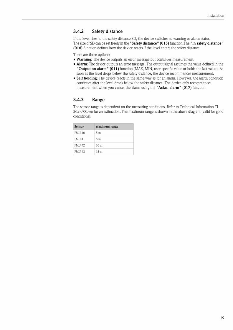
3.4.2 Safety distance
If the level rises to the safety distance SD, the device switches to warning or alarm status.
The size of SD can be set freely in the "Safety distance" (015) function.The "in safety distance"
(016) function defines how the device reacts if the level enters the safety distance.
There are three options:
• Warning: The device outputs an error message but continues measurement.
• Alarm: The device outputs an error message. The output signal assumes the value defined in the
"Output on alarm" (011) function (MAX, MIN, user-specific value or holds the last value). As
soon as the level drops below the safety distance, the device recommences measurement.
• Self holding: The device reacts in the same way as for an alarm. However, the alarm condition
continues after the level drops below the safety distance. The device only recommences
measurement when you cancel the alarm using the "Ackn. alarm" (017) function.
3.4.3 Range
The sensor range is dependent on the measuring conditions. Refer to Technical Information TI
365F/00/en for an estimation. The maximum range is shown in the above diagram (valid for good
conditions).
Sensor maximum range
FMU 40 5 m
FMU 41 8 m
FMU 42 10 m
FMU 43 15 m
Installation
20
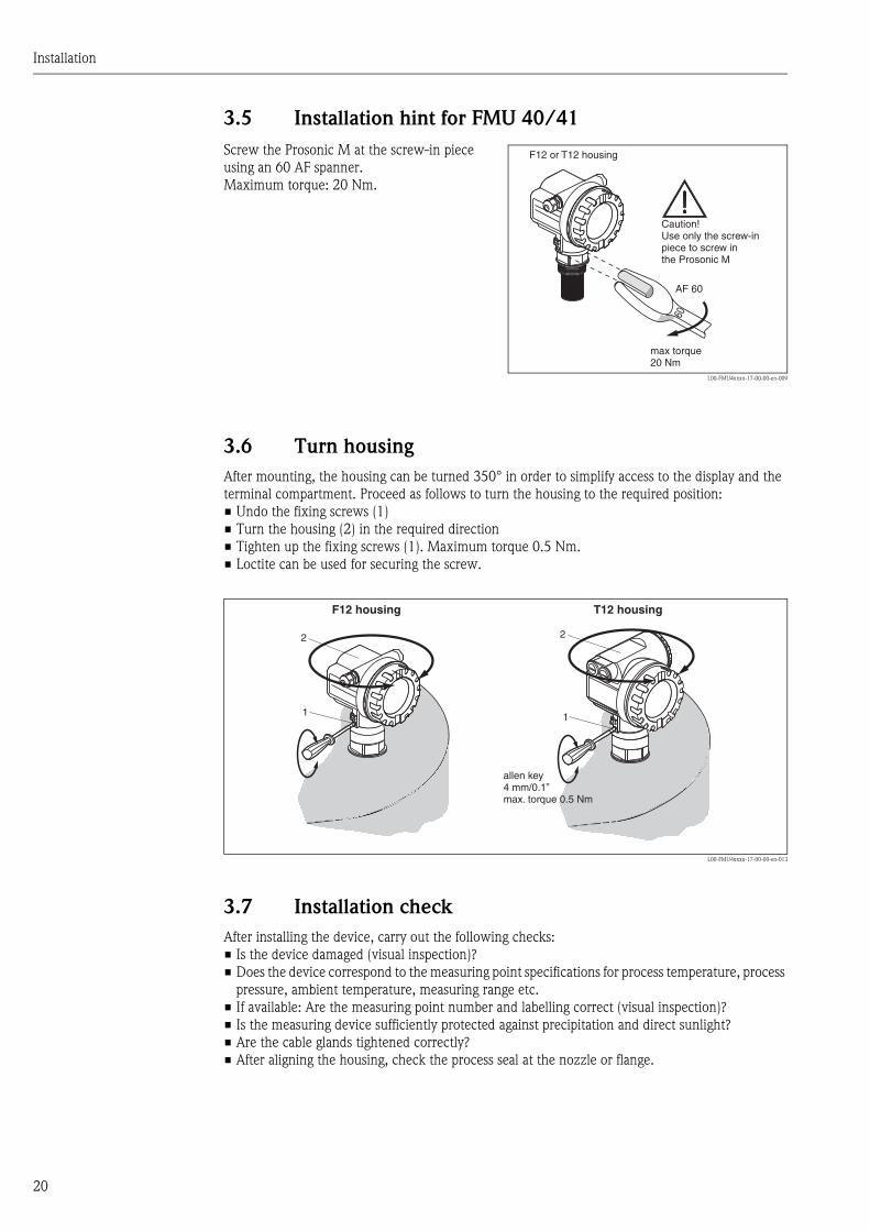
3.5 Installation hint for FMU 40/41
3.6 Turn housing
After mounting, the housing can be turned 350° in order to simplify access to the display and the
terminal compartment. Proceed as follows to turn the housing to the required position:
• Undo the fixing screws (1)
• Turn the housing (2) in the required direction
• Tighten up the fixing screws (1). Maximum torque 0.5 Nm.
• Loctite can be used for securing the screw.
L00-FMU4xxxx-17-00-00-en-013
3.7 Installation check
After installing the device, carry out the following checks:
• Is the device damaged (visual inspection)?
• Does the device correspond to the measuring point specifications for process temperature, process
pressure, ambient temperature, measuring range etc.
• If available: Are the measuring point number and labelling correct (visual inspection)?
• Is the measuring device sufficiently protected against precipitation and direct sunlight?
• Are the cable glands tightened correctly?
• After aligning the housing, check the process seal at the nozzle or flange.
Screw the Prosonic M at the screw-in piece
using an 60 AF spanner.
Maximum torque: 20 Nm.
L00-FMU4xxxx-17-00-00-en-009
60
AF 60
max torque20 Nm
Caution!Use only the screw-inpiece to screw inthe Prosonic M
F12 or T12 housing
11
2 2
F12 housing T12 housing
allen key4 mm/0.1”max. torque 0.5 Nm
Wiring
21
4 Wiring
4.1 Electrical connection
" Caution!
Before connection please note the following:
• The power supply must be identical to the data on the nameplate.
• Switch off power supply before connecting up the instrument.
• Connect equipotential bonding to transmitter ground terminal before connecting up the
instrument (s. section "Potential matching")
# Warning!
When you use the measuring system in hazardous areas, make sure to comply with national
standards and the specifications in the safety instructions (XA’s). Make sure you use the specified
cable gland.
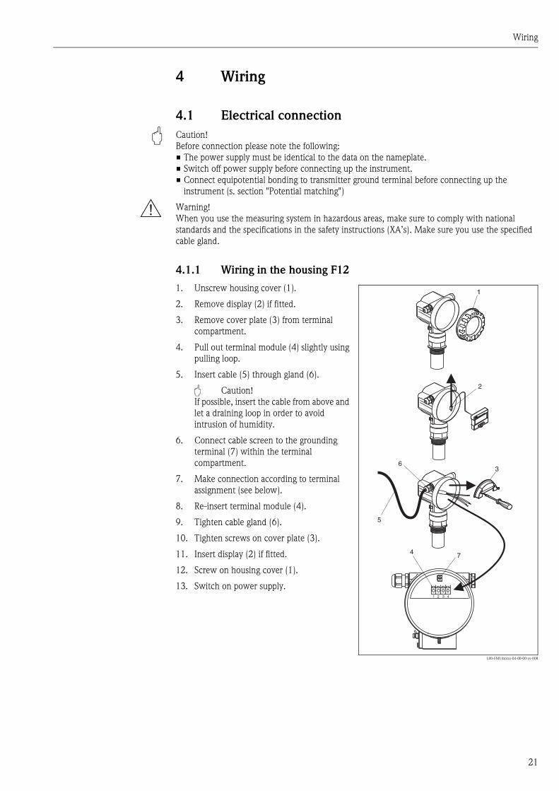
4.1.1 Wiring in the housing F12
1. Unscrew housing cover (1).
2. Remove display (2) if fitted.
3. Remove cover plate (3) from terminal
compartment.
4. Pull out terminal module (4) slightly using
pulling loop.
5. Insert cable (5) through gland (6).
" Caution!
If possible, insert the cable from above and
let a draining loop in order to avoid
intrusion of humidity.
6. Connect cable screen to the grounding
terminal (7) within the terminal
compartment.
7. Make connection according to terminal
assignment (see below).
8. Re-insert terminal module (4).
9. Tighten cable gland (6).
10. Tighten screws on cover plate (3).
11. Insert display (2) if fitted.
12. Screw on housing cover (1).
13. Switch on power supply.
L00-FMU4xxxx-04-00-00-yy-008
1 2 3 4
ENDRESS+HAUSER
ENDRESS+HAUSER
3
5
4
1
2
6
7

Wiring
22
4.1.2 Wiring in the housing T12
4.2 Terminal assignment
1. Unscrew the cover (1) of the separate
connection room.
2. Insert cable (2) through gland (3).
" Caution!
If possible, insert the cable from above and
let a draining loop in order to avoid
intrusion of humidity.
3. Connect cable screen to the grounding
terminal (4) within the connection room.
4. Make connection according to the terminal
assignment (see below).
5. Tighten cable gland (3).
6. Screw on housing cover (1).
7. Switch on power supply.
L00-FMU4xxxx-04-00-00-yy-009
3
2
1 2 3 4
4
1
Loop-powered version
L00-FMxxxxxx-04-00-00-en-015
4-wire version (active)
L00-FMxxxxxx-04-00-00-en-011
3 4I+ I-
1 2L- L+
4...20 mA
CommuboxFXA191/195DXR375
communicationresistor
(> 250 )W
alternatively
plantground
test sockets for testingof the signal current
power
5 6I+ I-
1 2L1/L+ N/L-
4...20mA
CommuboxFXA191/195DXR375
communicationresistor
(> 250 )W
alternatively
powerdisplay unit,recorder, PCS
AC / DCDC
plantground
Wiring
23
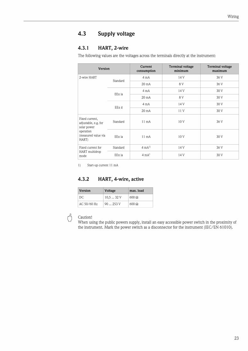
4.3 Supply voltage
4.3.1 HART, 2-wire
The following values are the voltages across the terminals directly at the instrument:
4.3.2 HART, 4-wire, active
" Caution!
When using the public powers supply, install an easy accessible power switch in the proximity of
the instrument. Mark the power switch as a disconnector for the instrument (IEC/EN 61010).
VersionCurrent
consumption
Terminal voltage
minimum
Terminal voltage
maximum
2-wire HARTStandard
4 mA 14 V 36 V
20 mA 8 V 36 V
EEx ia4 mA 14 V 30 V
20 mA 8 V 30 V
EEx d4 mA 14 V 30 V
20 mA 11 V 30 V
Fixed current,
adjustable, e.g. for
solar power
operation
(measured value via
HART)
Standard 11 mA 10 V 36 V
EEx ia 11 mA 10 V 30 V
Fixed current for
HART multidrop
mode
Standard 4 mA1)
1) Start-up current 11 mA
14 V 36 V
EEx ia 4 mA1 14 V 30 V
Version Voltage max. load
DC 10,5 ... 32 V 600 Ω
AC 50/60 Hz 90 ... 253 V 600 Ω
Wiring
24
4.4 Potential matching
L00-FMU4xxxx-17-00-00-yy-014
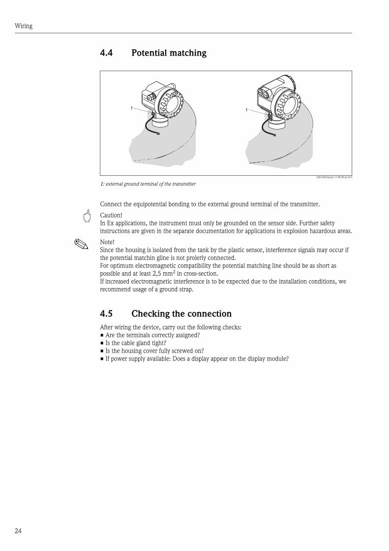
1: external ground terminal of the transmitter
Connect the equipotential bonding to the external ground terminal of the transmitter.
" Caution!
In Ex applications, the instrument must only be grounded on the sensor side. Further safety
instructions are given in the separate documentation for applications in explosion hazardous areas.
! Note!
Since the housing is isolated from the tank by the plastic sensor, interference signals may occur if
the potential matchin gline is not prolerly connected.
For optimum electromagnetic compatibility the potential matching line should be as short as
possible and at least 2,5 mm2 in cross-section.
If increased electromagnetic interference is to be expected due to the installation conditions, we
recommend usage of a ground strap.
4.5 Checking the connection
After wiring the device, carry out the following checks:
• Are the terminals correctly assigned?
• Is the cable gland tight?
• Is the housing cover fully screwed on?
• If power supply available: Does a display appear on the display module?
11
Operation
25
5 Operation
5.1 Display and operating elements
5.1.1 On-site display VU 331
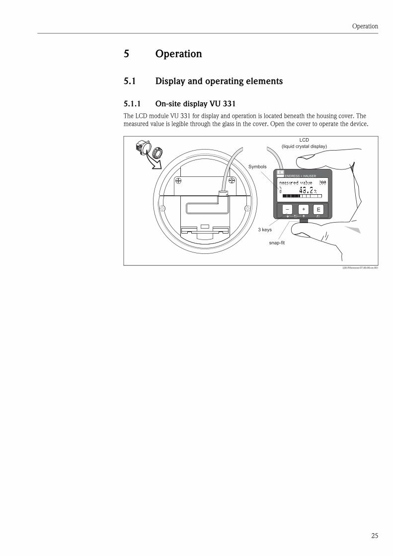
The LCD module VU 331 for display and operation is located beneath the housing cover. The
measured value is legible through the glass in the cover. Open the cover to operate the device.
L00-FMxxxxxx-07-00-00-en-001
ENDRESS + HAUSER
E+–
ENDRESS+HAUSER
MICROPILOT II
ENDRESS+HAUSER
MICROPILOT II
IP 65IP 65
Order Code:Ser.-No.:
Order Code:Ser.-No.:
MessbereichMeasuring range
MessbereichMeasuring rangeU 16...36 V DC
4...20 mA
U 16...36 V DC
4...20 mA
max. 20 m
max. 20 m
Ma
de
inG
erm
an
yM
au
lbu
rgM
ad
ein
Ge
rma
ny
Ma
ulb
urg
T>70°C :
A
t >85°C
T>70°C :
A
t >85°C
LCD(liquid crystal display)
Symbols
3 keys
snap-fit
Operation
26
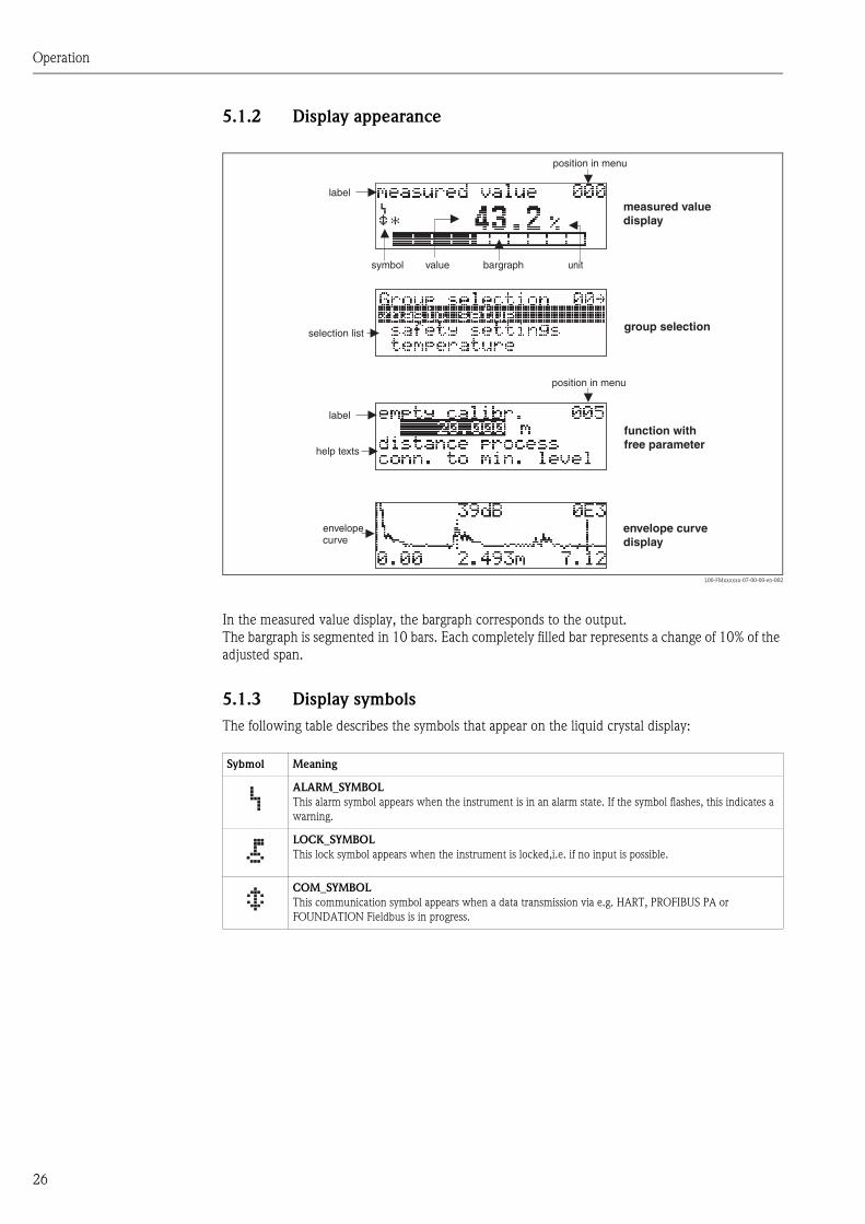
5.1.2 Display appearance
L00-FMxxxxxx-07-00-00-en-002
In the measured value display, the bargraph corresponds to the output.
The bargraph is segmented in 10 bars. Each completely filled bar represents a change of 10% of the
adjusted span.
5.1.3 Display symbols
The following table describes the symbols that appear on the liquid crystal display:
�
bargraph
help texts
envelopecurve
label
position in menu
value unitsymbol
measured valuedisplay
group selection
function withfree parameter
envelope curvedisplay
label
position in menu
selection list
Sybmol Meaning
ALARM_SYMBOL
This alarm symbol appears when the instrument is in an alarm state. If the symbol flashes, this indicates a
warning.
LOCK_SYMBOL
This lock symbol appears when the instrument is locked,i.e. if no input is possible.
COM_SYMBOL
This communication symbol appears when a data transmission via e.g. HART, PROFIBUS PA or
FOUNDATION Fieldbus is in progress.
Operation
27
5.1.4 Function of the keys
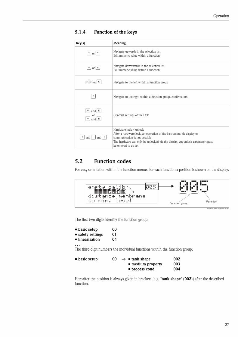
5.2 Function codes
For easy orientation within the function menus, for each function a position is shown on the display.
L00-FMU4xxxx-07-00-00-en-001
The first two digits identify the function group:
The third digit numbers the individual functions within the function group:
Hereafter the position is always given in brackets (e.g. "tank shape" (002)) after the described
function.
Key(s) Meaning
O or V Navigate upwards in the selection list
Edit numeric value within a function
S or W Navigate downwards in the selection list
Edit numeric value within a function
X or Z Navigate to the left within a function group
F Navigate to the right within a function group, confirmation.
O and For
S and FContrast settings of the LCD
O and S and F
Hardware lock / unlock
After a hardware lock, an operation of the instrument via display or
communication is not possible!
The hardware can only be unlocked via the display. An unlock parameter must
be entered to do so.
• basic setup 00
• safety settings 01
• linearisation 04
. . .
• basic setup 00 → • tank shape 002
• medium property 003
• process cond. 004
. . .
FunctionFunction group
���
Operation
28
5.3 Operating options
5.3.1 4…20 mA output with HART protocol
The complete measuring system consists of:
L00-FMxxxxxx-14-00-06-en-007
If the HART communication resistor is not built into the supply unit, it is necessary to insert a
communication resistor of 250 Ω into the 2-wire line.
ENDRESS + HAUSER
E+–
%
ENDRESS + HAUSERRMA 422
1# % &
Copy
G H I
P Q R S
, ( ) ‘
A B C
Paste
PageOn
PageUp
DeleteBksp
Insert
J K L
T U V
_ < >
D E F
Hot Key
+ Hot Key
M N O
W X Y Z
+ * /
4
7
.
2
5
8
0
375FIELD COMMUNICATOR
3
6
9
-
DELTABAR: * * * * * * * *ONLINE
1 QUICK SETUP2 OPERATING MENU
4 SV 0 °C3 PV 352 mbar
HELP SAVE
dsdmdmdf das.
asdas faasas la.
- ToF Tool -FieldToolPackage
- FieldCare
- ToF Tool -FieldToolPackage
HART handheldDXR375FXA191/195
orDXR375
transmitter powersupply unitRMA422or RN221N(communication resistorincluded)
PLC
CommuboxFXA191/195
operating anddisplay moduleVU331
service adapterFXA193
Netz(for 4-wire)
Operation
29
5.4 Operation using the on-site display VU 331
L00-FMU4xxxx-19-00-00-en-018
1. Change from Measured Value Display to Group Selection by pressing F.
2. Press S or O to select the required Function Group and confirm by pressing F.
The active selection is marked by a 3 in front of the menu text.
3. Activate Edit mode with O or S .
Selection menus
a. Select the required Parameter in selected function with S oder O .
b. F confirms selection; 3appears in front of the selected parameter.
c. F confirms the edited value; system quits edit mode.
d. O and S (= Q) interrupts selection; system quits edit mode.
Typing in numerals and text
a. Press O or S to edit the first character of the numeral / text.
b. F positions the cursor at the next character; continue with a. until you have completed
your input.
c. If a ↵ symbol appears at the cursor, press F to accept the value entered; system quits edit
mode.
d. If a ← symbol appears at the cursor, press F to return to the previous character (e.g. for
correction of entries).
e. O and S (= Q) interrupts selection; system quits edit mode.
4. Press F to select the next function.
5. Press O and S (= Q) once; return to previous function.
Press O and S (= Q) twice; return to Group Selection.
6. Press O and S (= Q) to return to Measured value display.
X XX
X
S
S S
OO O
F F
>3 s
F
ENDRESS + HAUSER
E+–
...
2x
...
...
������
����
��� ����
��� ����
���������
�������������������������
������������� �
�����������
������������
������!���
���������
!���"�������
������
����� ��
���������
��!���
��������
�� ������������
Operation
30
5.5 Operation using ToF Tool
The ToF Tool is a graphical operation software for instruments from Endress+Hauser. It is used to
support commissioning, securing of data, signal analysis and documentation of the instruments. It
is compatible with the following operating systems: WinNT4.0, Win2000 and WinXP.
The ToF Tool supports the following functions:
• Online configuration of transmitters
• Signal analysis via envelope curve
• Linearisation table (graphically supported creation, editing, importing and exporting)
• Loading and saving of instrument data (Upload/Download)
• Documentation of measuring point
! Note!
Further information you may find on the CD-ROM, which is enclosed to the instrument.
5.5.1 Connection options
• HART with Commubox FXA 191
• Service interface with adapter FXA 193
5.5.2 Menu guided commissioning
L00-FMU4xxxx-19-00-00-en-003
• You can find the function groups and functions of the device in the navigation bar.
• You can find the input fields for the parameters in the main window.
• If you click on a parameter name, the Help pages open with precise explanations of the required
input.

Operation
31
5.5.3 Envelope curve display
The ToF Tool offers easy analysis of the envelope curve via the "Envelope" menu:
L00-FMU4xxxx-19-00-00-en-004
Operation
32
5.6 Operation with Commuwin II
Commuwin II is an operating software with graphical support (MS Windows) for intelligent
transmitters with the communication protocols Rackbus, Rackbus RS-485, HART and PROFIBUS-
PA.
Commuwin II supports the following functions:
• Online configuration of transmitters
• Loading and saving of instrument data (Upload/Download)
• Orderly visualisation of measured values and limit values
• Display and recording of measured values with a line recorder
! Note!
Further information on Commuwin II is given in the following E+H documentation:
• System Information: SI 018F/00/en “Commuwin II”
• Operating Manual: BA 124F/00/en “Commuwin II” operating program
5.6.1 Operation
You make the settings using an operating matrix or via a graphic interface. Envelope curves can not
be display in Commuwin II.
5.6.2 Connection
The computer ist connected to the HART communicatain line via the Commubox FXA 191.
5.7 Operation using a HART handheld terminal DXR 375
The operating menu of the Prosonic M can be accessed via the HART handheld terminal DXR 375.
L00-FMU4xxxx-07-00-00-de-005
Connect the handheld terminal directly to the HART communication line.
1# % &
Copy
G H I
P Q R S
, ( ) ‘
A B C
Paste
PageOn
PageUp
DeleteBksp
Insert
J K L
T U V
_ < >
D E F
Hot Key
+ Hot Key
M N O
W X Y Z
+ * /
4
7
.
2
5
8
0
375FIELD COMMUNICATOR
3
6
9
-
9 6
FMU42: LIC0001ONLINE
1 GROUP SELECT2 PV 8.7 m
HELP SAVE
dsdmdmdf das.asdas faasas la.
PageOn
PageUp
Bksp
Delete
Delete
FMU43: LIC0001ONLINE
1 GROUP SELECTION2 PV 8.7 m
HELP SAVE
dsdmdmdf das.asdas faasas la.
FMU43: LIC0001GROUP SELECTION
HOMESAVE
dsdmdmdf das.asdas faasas la.H
FMRU43: LIC0001
HOMESAVE
dsdmdmdf das.asdas faasas la.H
Bksp
1 BASIC SETUP2 SAFETY SETTINGS
BASIC SETUP
1 MEASURED VALUE
4 PROCESS COND.
5 EMPTY CALIBR.
3 MEDIUM PROPERTY
4 LINEARISATION
5 EXTENDED CALIBR.
3 TEMPERATURE
2 TANK SHAPE

Operation
33
5.8 Lock/unlock configuration
5.8.1 Software security locking
Enter a number ¼ 100 in the "unlock parameter" (0A4) function in the "diagnostics" (0A)
function group.
The symbol appears on the display. Inputs are no longer possible.
If you try to change a parameter, the device jumps to the "unlock parameter" (0A4) function.
Enter "100"
Now change the parameters.
5.8.2 Hardware security locking
Press S, O and F simultaneously.
Inputs are no longer possible.
If you try to change a parameter, the following appears:
L00-fmrxf0a4-20-00-00-de-001
Press S, O and F simultaneously. The "unlock parameter" (0A4) function appears.
Enter "100"
Now change the parameters.
! Note!
A hardware locking can only be unlocked again via the display by pressing the O, S and F keys at
the same time again. It is not possible to unlock the hardware by communication.
5.9 Resetting the customer parameters
It is advisable to reset the customer parameters if you want to use a device with an unknown history.
Effects of resetting:
• All customer parameters are reset to their default values.
• Customer interference echo suppression is not deleted.
• Linearisation is switched to "linear", but the table values are kept. The table can be switched
back on in the "linearisation" (04) function group in the "linearisation" (041) function.
In order to carry out the reset, enter the number "33333" in the "reset" (0A3) function in the
"diagnostics" (0A) function group.
" Caution!
A reset may lead to impairment of the measurement. As a rule, a basic calibration is required after
a reset.
! Note!
The default values of each parameter are shown in bold in the menu overview in the appendix.
Operation
34
5.10 Resetting an interference echo suppression (tank map)
It is always advisable to reset the interference echo suppression (tank mapping) when:
• a device with an unknown history is used
• an incorrect suppression was input.
Proceed as follows:
1. Switch to the "extended calibr." (05) function group and to the "selection" (050)
function.
2. Select "extended map."
3. Then proceed to the "cust. tank map" (055) function.
4. Select
– "reset", to delete (reset) the existing interference echo suppression.
– "inactive" to deactivate an existing interference echo suppression. The suppression remains
saved.
– "active" to reactivate an existing interference echo suppression.
Commissioning
35
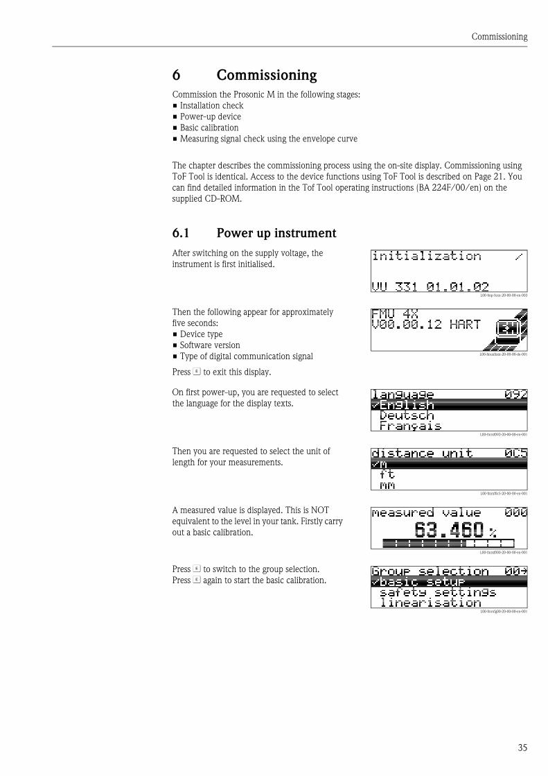
6 Commissioning
Commission the Prosonic M in the following stages:
• Installation check
• Power-up device
• Basic calibration
• Measuring signal check using the envelope curve
The chapter describes the commissioning process using the on-site display. Commissioning using
ToF Tool is identical. Access to the device functions using ToF Tool is described on Page 21. You
can find detailed information in the Tof Tool operating instructions (BA 224F/00/en) on the
supplied CD-ROM.
6.1 Power up instrument
After switching on the supply voltage, the
instrument is first initialised.
L00-fmp-fxxx-20-00-00-en-003
Then the following appear for approximately
five seconds:
• Device type
• Software version
• Type of digital communication signal
Press F to exit this display.
L00-fmuxfxxx-20-00-00-de-001
On first power-up, you are requested to select
the language for the display texts.
L00-fmrxf092-20-00-00-en-001
Then you are requested to select the unit of
length for your measurements.
L00-fmrxf0c5-20-00-00-en-001
A measured value is displayed. This is NOT
equivalent to the level in your tank. Firstly carry
out a basic calibration.
L00-fmrxf000-20-00-00-en-001
Press F to switch to the group selection.
Press F again to start the basic calibration.
L00-fmrxfg00-20-00-00-en-001
Commissioning
36
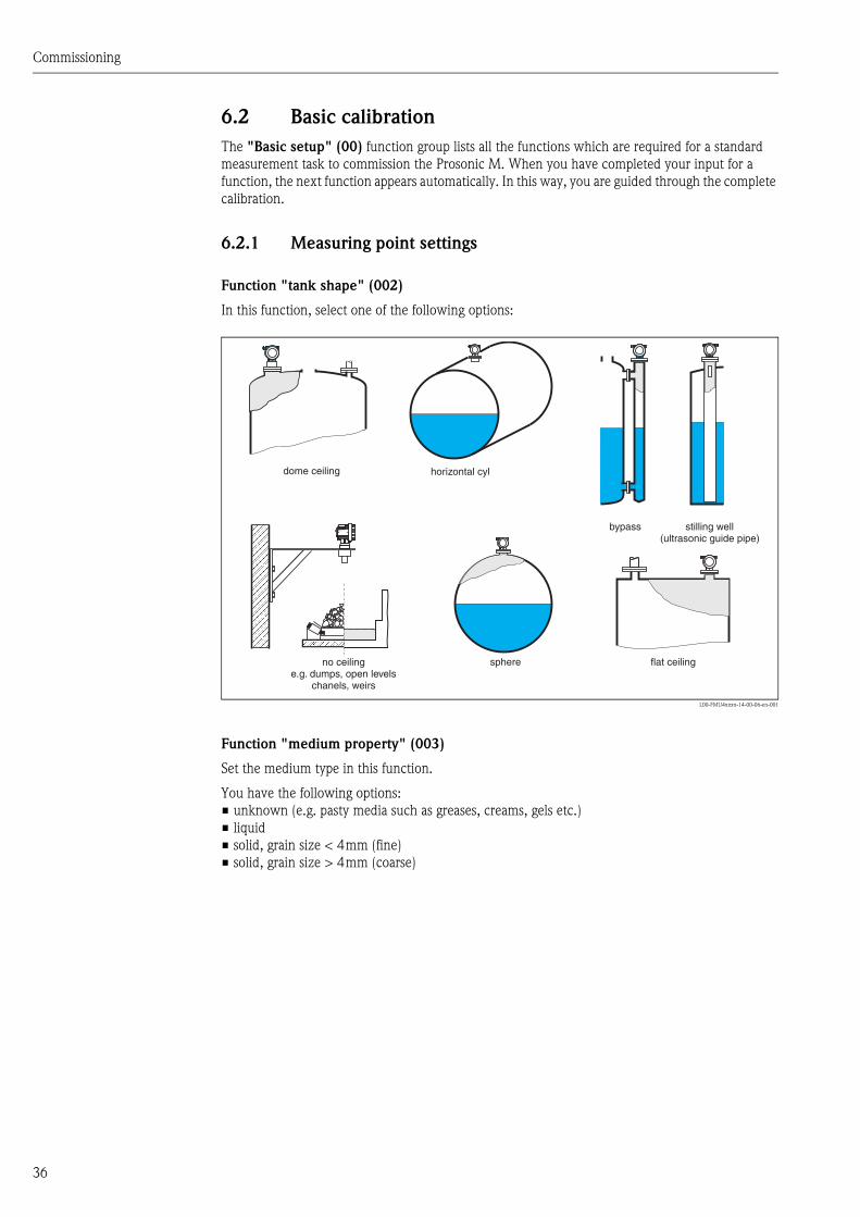
6.2 Basic calibration
The "Basic setup" (00) function group lists all the functions which are required for a standard
measurement task to commission the Prosonic M. When you have completed your input for a
function, the next function appears automatically. In this way, you are guided through the complete
calibration.
6.2.1 Measuring point settings
Function "tank shape" (002)
In this function, select one of the following options:
L00-FMU4xxxx-14-00-06-en-001
Function "medium property" (003)
Set the medium type in this function.
You have the following options:
• unknown (e.g. pasty media such as greases, creams, gels etc.)
• liquid
• solid, grain size < 4mm (fine)
• solid, grain size > 4mm (coarse)
ENDRESS+HAUSERProsonic M
dome ceiling
flat ceilingsphere
horizontal cyl
bypass stilling well(ultrasonic guide pipe)
no ceilinge.g. dumps, open levels
chanels, weirs
Commissioning
37
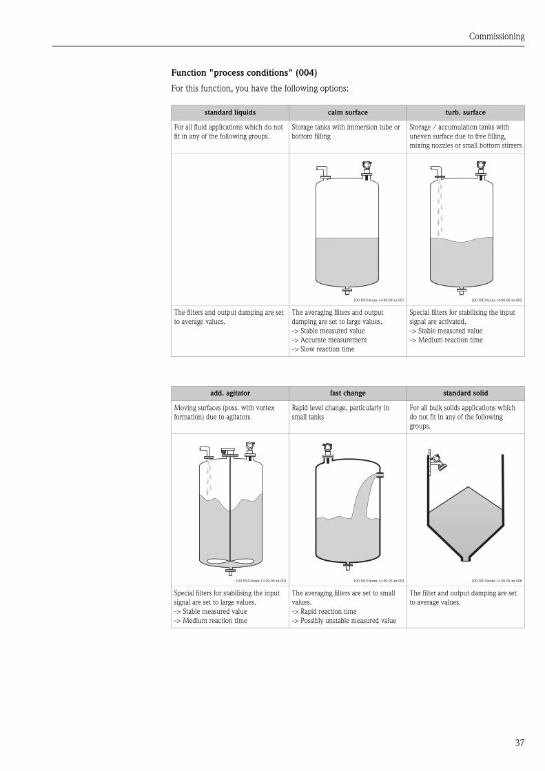
Function "process conditions" (004)
For this function, you have the following options:
standard liquids calm surface turb. surface
For all fluid applications which do not
fit in any of the following groups.
Storage tanks with immersion tube or
bottom filling
Storage / accumulation tanks with
uneven surface due to free filling,
mixing nozzles or small bottom stirrers
L00-FMU4xxxx-14-00-00-xx-001 L00-FMU4xxxx-14-00-00-xx-002
The filters and output damping are set
to average values.
The averaging filters and output
damping are set to large values.
-> Stable measured value
-> Accurate measurement
-> Slow reaction time
Special filters for stabilising the input
signal are activated.
-> Stable measured value
-> Medium reaction time
add. agitator fast change standard solid
Moving surfaces (poss. with vortex
formation) due to agitators
Rapid level change, particularly in
small tanks
For all bulk solids applications which
do not fit in any of the following
groups.
L00-FMU4xxxx-14-00-00-xx-003 L00-FMU4xxxx-14-00-00-xx-004 L00-FMU4xxxx-14-00-00-xx-006
Special filters for stabilising the input
signal are set to large values.
-> Stable measured value
-> Medium reaction time
The averaging filters are set to small
values.
-> Rapid reaction time
-> Possibly unstable measured value
The filter and output damping are set
to average values.
Commissioning
38
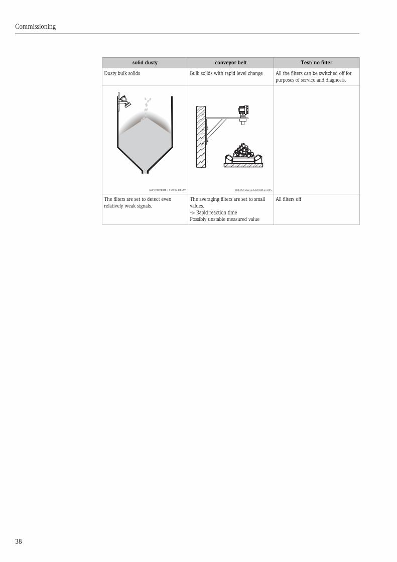
solid dusty conveyor belt Test: no filter
Dusty bulk solids Bulk solids with rapid level change All the filters can be switched off for
purposes of service and diagnosis.
L00-FMU4xxxx-14-00-00-xx-007 L00-FMU4xxxx-14-00-00-xx-005
The filters are set to detect even
relatively weak signals.
The averaging filters are set to small
values.
-> Rapid reaction time
Possibly unstable measured value
All filters off
ENDRESS+HAUSERProsonic M
Commissioning
39
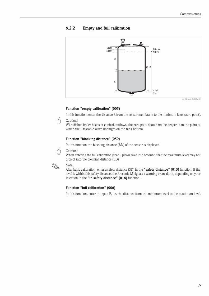
6.2.2 Empty and full calibration
L00-FMU4xxxx-19-00-00-yy-019
Function "empty calibration" (005)
In this function, enter the distance E from the sensor membrane to the minimum level (zero point).
" Caution!
With dished boiler heads or conical outflows, the zero point should not be deeper than the point at
which the ultrasonic wave impinges on the tank bottom.
Function "blocking distance" (059)
In this function the blocking distance (BD) of the sensor is displayed.
" Caution!
When entering the full calibration (span), please take into account, that the maximum level may not
project into the blocking distance (BD)
! Note!
After basic calibration, enter a safety distance (SD) in the "safety distance" (015) function. If the
level is within this safety distance, the Prosonic M signals a warning or an alarm, depending on your
selection in the "in safety distance" (016) function.
Function "full calibration" (006)
In this function, enter the span F, i.e. the distance from the minimum level to the maximum level.
20mA100%
4mA0%
D
L
FE
BDSD

Commissioning
40
6.2.3 Interference echo suppression (tank mapping)
Function "dist./measured value" (008)
In the "dist./meas.value" (008) function, the measured distance D from the sensor membrane
to the product surface is displayed together with level L. Check these values.
Function "check distance" (051)
The mapping is initialized by this function.
L00-FMR2xxxx-14-00-06-en-010
Select
• "distance=ok" if the correct distance is displayed. Any echoes closer to the sensor will be
suppressed by the following interference echo suppression.
• "dist. too small" if the displayed distance is too small. In this case, the signal comes from an
interference echo which will be suppressed.
• "dist. too big" if the displayed distance is too large. This error cannot be cancelled by suppressing
the interference echo. This means that the following two functions are skipped. Check the
application parameters "tank shape" (002), "medium proerty" (003) and "process
cond." (004) and the "empty calibr."(005) in the "basic setup" (00) function group.
• "dist. unknown" if you do not know the actual distance. This means that the following two
functions are skipped.
• "manual" if you want to specify the suppression area yourself in the following function.
Function "range of mapping" (052)
The suggested suppression area is displayed in this function. The reference point is always the sensor
membrane. You can still edit the value. With manual suppression, the default value is 0 m.
" Caution!
The suppression range must end 0.5 m in front of the echo of the actual level. With an empty tank,
do not enter E but E – 0.5 m.

Commissioning
41
Function "start mapping" (053)
You have the following options for this function:
• off: Nothing is suppressed.
• on: Starts suppression.
! Note!
If a mapping already exists, it will be overwritten up to the distance specified in the "range of
mapping" (052) function. Beyond this distance the existing mapping remains unchanged.
Function dist./measured value (008)
After suppression, the measured distance D from the sensor membrane to the product surface is
displayed together with the level. Check that the values correspond to the actual level and/or the
actual distance.
The following cases may occur:
• Distance correct – Level correct -> End of basic calibration
• Distance incorrect – Level incorrect -> An additional interference echo suppression must be
carried out. Go back to the "check distance" (051) function.
• Distance correct – Level incorrect -> Check the value of the "empty calibr." (005) function.
Rücksprung zur Gruppenauswahl
Nach der Störechoausblendung ist der Grundabgleich beendet und das Gerät springt automatisch
in die Gruppenauswahl zurück.
Commissioning
42
6.3 Envelope curve
After the basic setup, an evaluation of the measurement with the aid of the envelope curve
("envelope curve" (0E) function group) is recommended.
6.3.1 Funxtion "plot settings" (0E1)
In this function, select whether you want to display
• just the envelope curve
• The envelope curve and the echo evaluation line FAC
• The envelope curve and interference echo suppression (map)
! Note!
The FAC and the interference echo suppression (map) are explained in BA 240F "Prosonic M -
Description of Instrument Functions"
6.3.2 Function "recording curve" (0E2)
In this function, specify whether you want to display
• an individual envelope curve
• The current envelope curve, with cyclical refreshment.
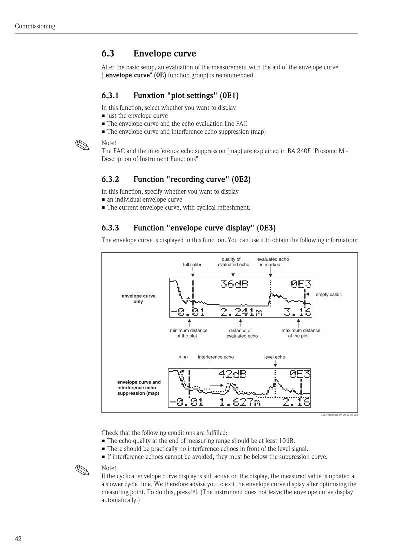
6.3.3 Function "envelope curve display" (0E3)
The envelope curve is displayed in this function. You can use it to obtain the following information:
L00-FMU4xxxx-07-00-00-en-003
Check that the following conditions are fulfilled:
• The echo quality at the end of measuring range should be at least 10dB.
• There should be practically no interference echoes in front of the level signal.
• If interference echoes cannot be avoided, they must be below the suppression curve.
! Note!
If the cyclical envelope curve display is still active on the display, the measured value is updated at
a slower cycle time. We therefore advise you to exit the envelope curve display after optimising the
measuring point. To do this, press F. (The instrument does not leave the envelope curve display
automatically.)
minimum distanceof the plot
maximum distanceof the plot
distance ofevaluated echo
interference echo
evaluated echois marked
quality ofevaluated echo
empty calibr.envelope curveonly
envelope curve andinterference echosuppression (map)
level echomap
full calibr.

Commissioning
43
6.3.4 Navigation in the envelope curve display
Using navigation, the envelope curve can be scaled horizontally and vertically and shifted to the left
or the right. The active navigation mode is indicated by a symbol in the top left hand corner of the
display.
L00-FMxxxxxx-07-00-00-en-004
Horizontal Zoom mode
Firstly, go into the envelope curve display. Then press O or S to switch to the envelope curve
navigation. You are then in Horizontal Zoom mode. Either or is displayed.
• O increases the horizontal scale.
• S reduces the horizontal scale.
L00-FMxxxxxx-07-00-00-yy-007
Move mode
Then press F to switch to Move mode. Either or is displayed.
• O shifts the curve to the right.
• S shifts the curve to the left.
L00-FMxxxxxx-07-00-00-yy-008
Vertical Zoom mode
Press F once more to switch to Vertical Zoom mode. is displayed. You now have the following
options.
• O increases the vertical scale.
• S reduces the vertical scale.
The display icon shows the current zoom factor ( to ).
L00-FMxxxxxx-07-00-00-yy-009
…
#$%
Move mode:
- m
-
oved to the left
moved to the right
Horizontal Zoom mode:
- h
-
orizontal zoom in
horizontal zoom out
Vertical Zoom mode:
- vertical zoom (4 steps)
OS
OS
OS

Commissioning
44
Exiting the navigation
• Press F again to run through the different modes of the envelope curve navigation.
• Press O and S to exit the navigation. The set increases and shifts are retained. Only when you
reactivate the "recording curve" (0E2) function the display settings return to their standard
values.
Troubleshooting
45
7 Troubleshooting
7.1 System error messages
7.1.1 Current error
Errors which the Prosonic M detects during commissioning or operation are displayed:
• In the "measured value" (000) function
• In the "diagnostics" (0A) function group in the "present error" (0A0) function
Only the highest priority error is displayed; in the case of multiple errors, you can scroll between
the different error messages by pressing O or S.
7.1.2 Last error
The last error is displayed in the "diagnostics" (0A) function group in the "previous error"
(0A1) function. This display can be deleted in the "clear last error" (0A2) function.
7.1.3 Types of error
7.1.4 Error codes
Type of error Symbol Meaning
Alarm (A)
continuous
The output signal assumes a value which can be set using the "output
on alarm" (010) function:
• MAX: 110%, 22mA
• MIN: -10%, 3,8mA
• Hold: last value is on hold
• User-specific value
Warning (W)
flashing
The device continues measurement. An error message is displayed.
Alarm/Warning (E) You can define whether the error should behave as an alarm or as a warning.
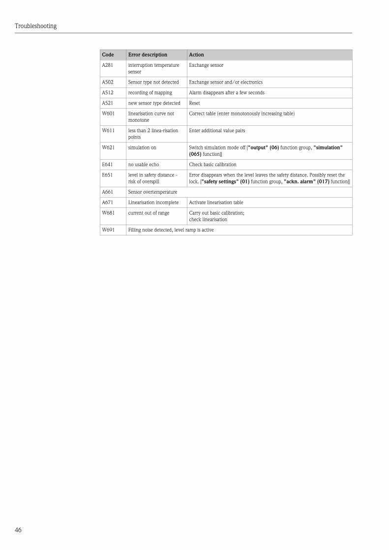
Code Error description Action
A102
A110
A152
A160
checksum error Reset;
If alarm still present after reset, replace electronics
W103 initialising If the message does not disappear after several seconds, replace the electronics
A106 downloading Wait; Message disappears after load sequence
A111
A113
A114
A115
A121
A125
A155
A164
A171
electronics defect Reset;
Check system for EMC, improve as necessary
If alarm still present after reset, replace electronics
A116 download error Check connection; Restart download
W153 initialising Wait a few seconds; if error is still displayed, switch the power off and on again
A231 sensor defect Check connection, if necessary replace HF module or electronics
Troubleshooting
46
A281 interruption temperature
sensor
Exchange sensor
A502 Sensor type not detected Exchange sensor and/or electronics
A512 recording of mapping Alarm disappears after a few seconds
A521 new sensor type detected Reset
W601 linearisation curve not
monotone
Correct table (enter monotonously increasing table)
W611 less than 2 linea-risation
points
Enter additional value pairs
W621 simulation on Switch simulation mode off ["output" (06) function group, "simulation"
(065) function]]
E641 no usable echo Check basic calibration
E651 level in safety distance -
risk of overspill
Error disappears when the level leaves the safety distance. Possibly reset the
lock. ["safety settings" (01) function group, "ackn. alarm" (017) function]]
A661 Sensor overtemperature
A671 Linearisation incomplete Activate linearisation table
W681 current out of range Carry out basic calibration;
check linearisation
W691 Filling noise detected, level ramp is active
Code Error description Action
Troubleshooting
47
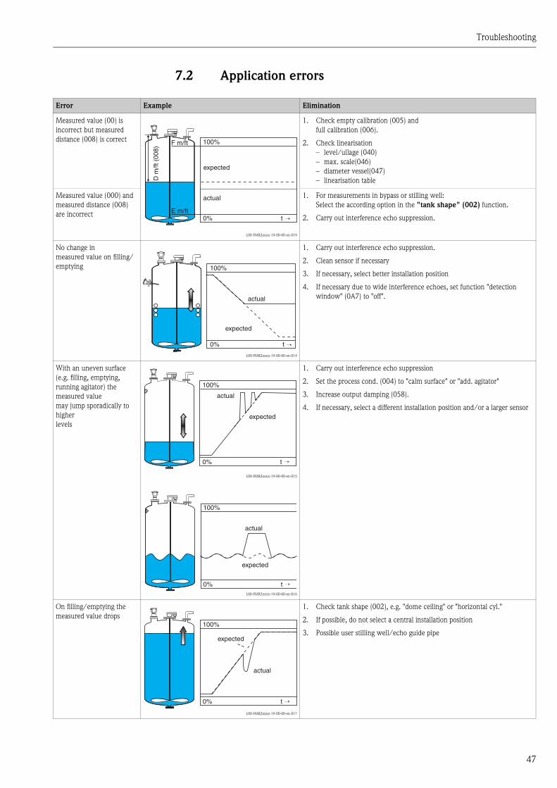
7.2 Application errors
Error Example Elimination
Measured value (00) is
incorrect but measured
distance (008) is correct
L00-FMR2xxxx-19-00-00-en-019
1. Check empty calibration (005) and
full calibration (006).
2. Check linearisation
– level/ullage (040)
– max. scale(046)
– diameter vessel(047)
– linearisation table
Measured value (000) and
measured distance (008)
are incorrect
1. For measurements in bypass or stilling well:
Select the according option in the "tank shape" (002) function.
2. Carry out interference echo suppression.
No change in
measured value on filling/
emptying
L00-FMR2xxxx-19-00-00-en-014
1. Carry out interference echo suppression.
2. Clean sensor if necessary
3. If necessary, select better installation position
4. If necessary due to wide interference echoes, set function "detection
window" (0A7) to "off".
With an uneven surface
(e.g. filling, emptying,
running agitator) the
measured value
may jump sporadically to
higher
levels
L00-FMR2xxxx-19-00-00-en-015
L00-FMR2xxxx-19-00-00-en-016
1. Carry out interference echo suppression
2. Set the process cond. (004) to "calm surface" or "add. agitator"
3. Increase output damping (058).
4. If necessary, select a different installation position and/or a larger sensor
On filling/emptying the
measured value drops
L00-FMR2xxxx-19-00-00-en-017
1. Check tank shape (002), e.g. "dome ceiling" or "horizontal cyl."
2. If possible, do not select a central installation position
3. Possible user stilling well/echo guide pipe
100%F m/ft
E m/ft0% t →
D m
/ft (
008)
actual
expected
100%
0% t →
actual
expected
100%
0% t →
actual
expected
100%
0% t →
actual
expected
100%
0% t →
actual
expected

Troubleshooting
48
E 641 (echo loss)
L00-FMR2xxxx-19-00-00-en-018
1. Check application parameters (002), (003) and (004)
2. If necessary, select a different installation position and/or a larger sensor
3. Align the sensor parallel to the product surface (particularly for bulk solids
applications)
Error Example Elimination
100%
E 641
0% t →
eingetreten
erwartet

Maintenance and repairs
49
8 Maintenance and repairs
8.1 Exterior cleaning
When cleaning the exterior, always use cleaning agents that do not attack the surface of the housing
and the seals.
8.2 Repairs
The Endress+Hauser repair concept assumes that the measuring devices have a modular design and
that customers are able to undertake repairs themselves.
Spare parts are contained in suitable kits. They contain the related replacement instructions.
All the spare parts kits which you can order from Endress+Hauser for repairs are listed with their
order numbers in the section "Spare parts".
For more information on service and spare parts, contact the Service Department at
Endress+Hauser.
8.3 Repairs to Ex-approved devices
When carrying out repairs to Ex-approved devices, please note the following:
• Repairs to Ex-approved devices may only be carried out by trained personnel or by the
Endress+Hauser Service.
• Comply with the prevailing standards, national Ex-area regulations, safety instructions (XA) and
certificates.
• Only use original spare parts from Endress+Hauser.
• When ordering a spare part, please note the device designation on the nameplate. Only replace
parts with identical parts.
• Carry out repairs according to the instructions. On completion of repairs, carry our the specified
routine test on the device.
• Only Endress+Hauser Service may convert a certified device into a different certified variant.
• Document all repair work and conversions.
8.4 Replacement
After a complete instrument or electronic module has been replaced, the parameters can be
downloaded into the instrument again via the communication interface. Prerequisite to this is that
the data were uploaded to the PC beforehand using the ToF Tool / Commuwin II. Measurement
can continue without having to carry out a new setup. Only a linearisation and a tank map
(interference echo suppression) have to be recorded again.
Maintenance and repairs
50
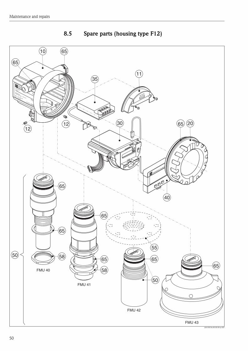
8.5 Spare parts (housing type F12)
L00-FMU4x-00-00-00-yy-007
12
50
58
58 65
65
65
65
11
65
65
65
40
ENDRESS+HAUSER
PROSONIC M
IP 65
Order Code:Ser.-No.:
MessbereichMeasuring rangeU 16...36 V DC
4...20 mA
max. 20 m
Ma
de
in G
erm
any
Ma
ulb
urg
Ma
de
in G
erm
any
Ma
ulb
urg
T>70°C :
A
t >85°C
12
34
Terminal
ENDRESS+HAUSER
FMU 40
FMU 41
FMU 43
35
65 2030
10
12
50
65
55
FMU 42
Maintenance and repairs
51
10 Housing
543120-0022 Housing F12, aluminium, G1/2
543120-0023 Housing F12, aluminium, NPT1/2
543120-0024 Housing F12, aluminium, M20
52001992 Housing F12, aluminium, M20, PA connector
52008556 Housing F12, aluminium, M20, FF connector
52013350 Housing F12, aluminium, coated, M20, 4-wire
52013351 Housing F12, aluminium, coated, M20, metal
52013348 Housing F12, aluminium, coated, G1/2, 4-wire
52013349 Housing F12, aluminium, coated, NPT1/2, 4-wire
11 Hood for terminal compartment
52006026 Cover for the connection compartment F12
52019062 Cover for the connection compartment F12, FHX40
12 Set of screws
535720-9020 Set of screws for housing F12/T12
20 Cover
52005936 Cover F12/T12 aluminium, inspection glass, seal
517391-0011 Cover F12/T12 aluminium, coated, seal
30 Electronics
71025600 electronics FMU4x, Ex, 2-wire HART, V4.0
71025602 electronics FMU4x, Ex, 4-wire HART, V4.0
71025603 electronics FMU4x, Ex, PROFIBUS PA, V4.0
52023759 Electronics Prosonic M, Ex, FF, V2.04
35 Terminal module / power unit
52006197 Terminal module 4-pin, HART, 2-wire with connecting cable
52012156 Terminal module 4-pin, PROFIBUS PA, Foundation Fieldbus
52013304 Power unit, 10.5...32V DC (housing F12) for electronics, 4-wire
52013305 Power unit, 90 ...250V AC (housing F12) for electronics, 4-wire
52015585 Power unit, CSA, 10.5...32V DC (housing F12) for electronics, 4-wire
52015586 Power unit, CSA, 90...250V AC (housing F12) for electronics, 4-wire
40 Display
52005585 Display/operating module VU331
50 Probe with process connection
52010509 Sensor FMU40 G1-1/2
52010507 Sensor FMU40 NPT1-1/2
52010510 Sensor FMU41 G2
52010508 Sensor FMU41 NPT2
52023965 Sensor FMU42
52013543 Sensor FMU43 4", gasket
Maintenance and repairs
52
55 Flanges
52023919 Flange, Uni-DN80/ANSI 3"/JIS 80A, PP
52023920 Flange, Uni-DN80/ANSI 3"/JIS 80A, PVDF
52023921 Flange, Uni-DN80/ANSI 3"/JIS 80A, 316L
52023922 Flange, Uni-DN100/ANSI 4"/JIS 100A, PP
52023923 Flange, Uni-DN100/ANSI 4"/JIS 100A, PVDF
58 Hexagon nut
52000599 Hexagon nut (SW60) G1-1/2, bk, PC
52000598 Hexagon nut (SW70) G2, bk, PC
65 Sealing kit
52010526 Sealing kit FMU4x
Miscellaneous
52010545 Nameplate Prosonic M, modification
Spare parts for FHX40
52018204 Adaption kit housing F12, 2-wire, FHX40
52018205 Adaption kit housing F12, 4-wire, FHX40
52016334 Cable FHX40, 20m
Maintenance and repairs
53
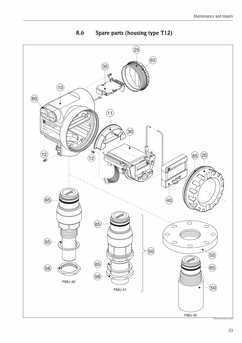
8.6 Spare parts (housing type T12)
L00-FMU4x-00-00-00-yy-008
ENDRESS+HAUSER
PROSONIC FMU
IP 65
Order Code:Ser.-No.:
MessbereichMeasuring rangeU 16...36 V DC
4...20 mA
max. 20 m
Made in
Germ
any
M
aulb
urg
Made in
Germ
any
M
aulb
urg
T>70°C :
A
t >85°C
ENDRESS+HAUSER
65
25
35
1212
50
50
58
58
10
65
11
30
65
65
65
65
65
40
20
FMU 40
FMU 41
65
55
FMU 42
Maintenance and repairs
54
10 Housing
543180-1023 Housing T12, aluminium, NPT1/2, PEL
52006204 Housing T12, aluminium, G1/2, PEL, cover
52006205 Housing T12, aluminium, M20, PEL, cover
11 Hood for terminal compartment
52005643 Hood T12
12 Set of screws
535720-9020 Set of screws for housing F12/T12
20 Cover
52005936 Cover F12/T12 aluminium, inspection glass, seal
517391-0011 Cover F12/T12 aluminium, coated, seal
25 Cover for the connection compartment
518710-0020 Cover T3/T12, aluminium, coated, seal
30 Electronics
71025600 electronics FMU4x, Ex, 2-wire HART, V4.0
71025603 electronics FMU4x, Ex, PROFIBUS PA, V4.0
52023759 Electronics Prosonic M, Ex, FF, V2.04
35 Terminal module / power unit
52013302 Terminal module Ex d, 4-pin, 2-wire, HART, T12
52013303 Terminal module Ex d, 2-pin, 2-wire, PROFIBUS PA, Foundation Fieldbus, T12
52018949 Terminal module EEx ia, 4-pin, HART, T12, OVP
52018950 Terminal module EEx ia, 4-pin, PROFIBUS PA, Foundation Fieldbus, T12, OVP
40 Display
52005585 Display/operating module VU331
50 Probe with process connection
52010509 Sensor FMU40 G1-1/2
52010507 Sensor FMU40 NPT1-1/2
52010510 Sensor FMU41 G2
52010508 Sensor FMU41 NPT2
52023965 Sensor FMU42
55 Flanges
52023919 Flange, Uni-DN80/ANSI 3"/JIS 80A, PP
52023920 Flange, Uni-DN80/ANSI 3"/JIS 80A, PVDF
52023921 Flange, Uni-DN80/ANSI 3"/JIS 80A, 316L
52023922 Flange, Uni-DN100/ANSI 4"/JIS 100A, PP
52023923 Flange, Uni-DN100/ANSI 4"/JIS 100A, PVDF
52023924 Flange, Uni-DN100/ANSI 4"/JIS 100A, 316L

Maintenance and repairs
55
58 Hexagon nut
52000599 Hexagon nut (SW60) G1-1/2, bk, PC
52000598 Hexagon nut (SW70) G2, bk, PC
65 Sealing kit
52010526 Sealing kit FMU4x
Miscellaneous
52010545 Nameplate Prosonic M, modification

Maintenance and repairs
56
8.7 Return
The following procedures must be carried out before a transmitter is sent to Endress+Hauser e.g.
for repair or calibration:
• Remove all residue which may be present. Pay special attention to the gasket grooves and crevices
where fluid may be present. This is especially important if the fluid is dangerous to health, e.g.
corrosive, poisonous, carcinogenic, radioactive, etc.
• Always enclose a duly completed "Declaration of contamination" form (a copy of the “Declaration
of contamination” is included at the end of this operating manual). Only then can Endress
+Hauser transport, examine and repair a returned device.
• Enclose special handling instructions if necessary, for example a safety data sheet as per EN 91/
155/EEC.
Additionally specify:
• An exact description of the application.
• The chemical and physical characteristics of the product.
• A short description of the error that occurred (specify error code if possible)
• Operating time of the device.
8.8 Disposal
In case of disposal please seperate the different components according to their material consistence.
In case of disposal please seperate the different components according to their material consistence.
8.9 Software history
8.10 Contact addresses of Endress+Hauser
Contact addresses can be found on our homepage: www.endress.com/worldwide. If you have any
questions, please do not hesitate to contact your Endress+Hauser representative.
Software version / date Changes to software Changes to documentation
V 01.02.00 / 01.2002
V 01.02.02 / 03.2003
Original software
Compatible with:
• ToF Tool
• Commuwin II (version 2.05.03 and
higher
• HART Communicator DXR 275 (from
OS 4.6) with Rev. 1, DD 1
V 01.02.04/02.2004 • FMU 42 added
• compatible with HART Communicator
DXR 375
FMU 42 added
V 01.04.00/07.2006 • "detection window" function added
can be operated via:
• ToF Tool from version 4.50
• HART Communicator DXR375 with
Rev. 1, DD1
"detection window" added
Version: 07.06
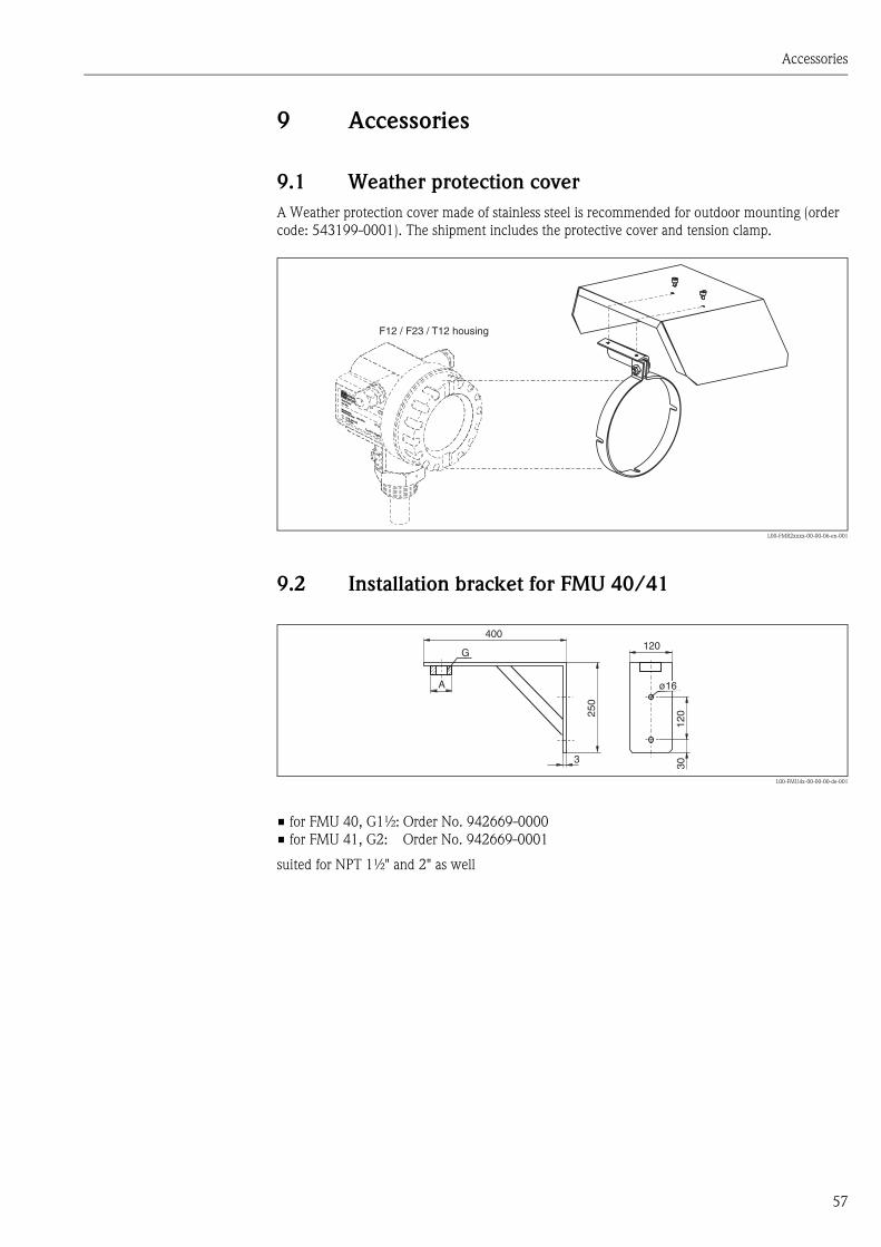
Accessories
57
9 Accessories
9.1 Weather protection cover
A Weather protection cover made of stainless steel is recommended for outdoor mounting (order
code: 543199-0001). The shipment includes the protective cover and tension clamp.
L00-FMR2xxxx-00-00-06-en-001
9.2 Installation bracket for FMU 40/41
L00-FMU4x-00-00-00-de-001
• for FMU 40, G1½: Order No. 942669-0000
• for FMU 41, G2: Order No. 942669-0001
suited for NPT 1½" and 2" as well
ENDRESS+HAUSER
MICROPILOT II
ENDRESS+HAUSER
MICROPILOT II
IP 65
Order Code:Ser.-No.:
Order Code:Ser.-No.:
MessbereichMeasuring range
MessbereichMeasuring rangeU 16...36 V DC
4...20 mA
U 16...36 V DC4...20 mA
max. 20 m
max. 20 m
Made in
Germ
any
Maulb
urg
Made in
Germ
any
Maulb
urg
T>70°C :
A
t >85°C
T>70°C :
A
t >85°C
F12 / F23 / T12 housing
400120
120
30
250
A
G
ø16
3
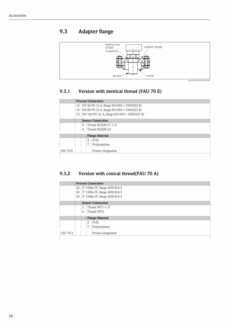
Accessories
58
9.3 Adapter flange
L00-FMUX3XXX-00-00-00-en-001
9.3.1 Version with metrical thread (FAU 70 E)
9.3.2 Version with conical thread(FAU 70 A)
Process Connection
12 DN 50 PN 16 A, flange EN1092-1 (DIN2527 B)
14 DN 80 PN 16 A, flange EN1092-1 (DIN2527 B)
15 DN 100 PN 16, A, flange EN1092-1 (DIN2527 B)
Sensor Connection
3 Thread ISO228 G1-1/2
4 Thread ISO228 G2
Flange Material
2 316L
7 Polypropylene
FAU 70 E Product designation
Process Connection
22 2" 150lbs FF, flange ANSI B16.5
24 3" 150lbs FF, flange ANSI B16.5
25 4" 150lbs FF, flange ANSI B16.5
Sensor Connection
5 Thread NPT1-1/2
6 Thread NPT2
Flange Material
2 316L
7 Polypropylene
FAU 70 A Product designation
adapter flangesealing ringEPDM(supplied)
sensor nozzle

Accessories
59
9.4 Cantilever
L00-FMU4xxxx-06-00-00-yy-005
• The 50 mm or 62 mm orifices serve for the mounting of the FMU 40 or FMU 41 sensor,
respecitvely.
• The 22 mm orifice may be used for an additional sensor.
A B C D for Sensor Material Order Code
585 mm 250 mm 2 mm 200 mm FMU 40 1.4301 (AISI 304) 52014132
galv. steel 52014131
FMU 41 1.4301 (AISI 304) 52014136
galv. steel 52014135
1085 mm 750 mm 3 mm 300 mm FMU 40 1.4301 (AISI 304) 52014134
galv. steel 52014133
FMU 41 1.4301 (AISI 304) 52014138
galv. steel 52014137
A
D M8
35 50
20
2010
5
50/
62 22
C
C
6.5 15
100
25
351007575 B
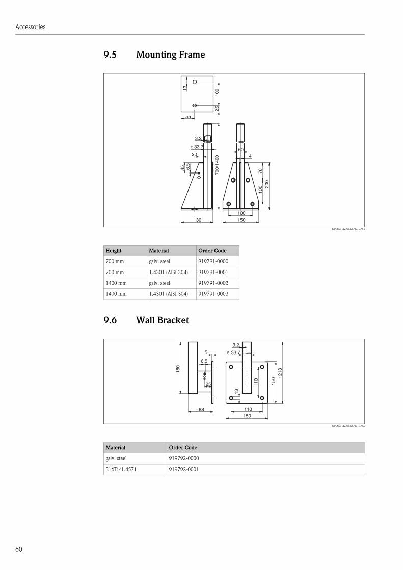
Accessories
60
9.5 Mounting Frame
L00-FMU4x-00-00-00-yy-005
9.6 Wall Bracket
L00-FMU4x-00-00-00-yy-006
Height Material Order Code
700 mm galv. steel 919791-0000
700 mm 1.4301 (AISI 304) 919791-0001
1400 mm galv. steel 919791-0002
1400 mm 1.4301 (AISI 304) 919791-0003
Material Order Code
galv. steel 919792-0000
316Ti/1.4571 919792-0001
3.2
20
55
100
2570
0/14
00
45
7610
0 200
6.5
13
Ø 33.7
130 150100
604
110
25
5
6.5
150
ø 33.7
3.2
110
13
150
180
213
88
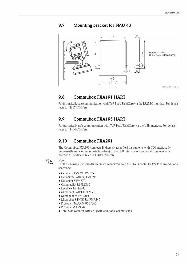
Accessories
61
9.7 Mounting bracket for FMU 43
L00-FMU4x-00-00-00-en-003.eps
9.8 Commubox FXA191 HART
For intrinsically safe communication with ToF Tool/FieldCare via the RS232C interface. For details
refer to TI237F/00/en.
9.9 Commubox FXA195 HART
For intrinsically safe communication with ToF Tool/FieldCare via the USB interface. For details
refer to TI404F/00/en.
9.10 Commubox FXA291
The Commubox FXA291 connects Endress+Hauser field instruments with CDI interface (=
Endress+Hauser Common Data Interface) to the USB interface of a personal computer or a
notebook. For details refer to TI405C/07/en.
! Note!
For the following Endress+Hauser instruments you need the "ToF Adapter FXA291" as an additional
accessory:
• Cerabar S PMC71, PMP7x
• Deltabar S PMD7x, FMD7x
• Deltapilot S FMB70
• Gammapilot M FMG60
• Levelflex M FMP4x
• Micropilot FMR130/FMR131
• Micropilot M FMR2xx
• Micropilot S FMR53x, FMR540
• Prosonic FMU860/861/862
• Prosonic M FMU4x
• Tank Side Monitor NRF590 (with additional adapter cable)
11
119
2
25
120
~12
3
25
Material: 1.4301Order-Code.: 942666-0000
Accessories
62
9.11 ToF Adapter FXA291
The ToF Adapter FXA291 connects the Commubox FXA291 via the USB interface of a personal
computer or a notebook to the following Endress+Hauser instruments:
• Cerabar S PMC71, PMP7x
• Deltabar S PMD7x, FMD7x
• Deltapilot S FMB70
• Gammapilot M FMG60
• Levelflex M FMP4x
• Micropilot FMR130/FMR131
• Micropilot M FMR2xx
• Micropilot S FMR53x, FMR540
• Prosonic FMU860/861/862
• Prosonic M FMU4x
• Tank Side Monitor NRF590 (with additional adapter cable)
For details refer to KA271F/00/a2.
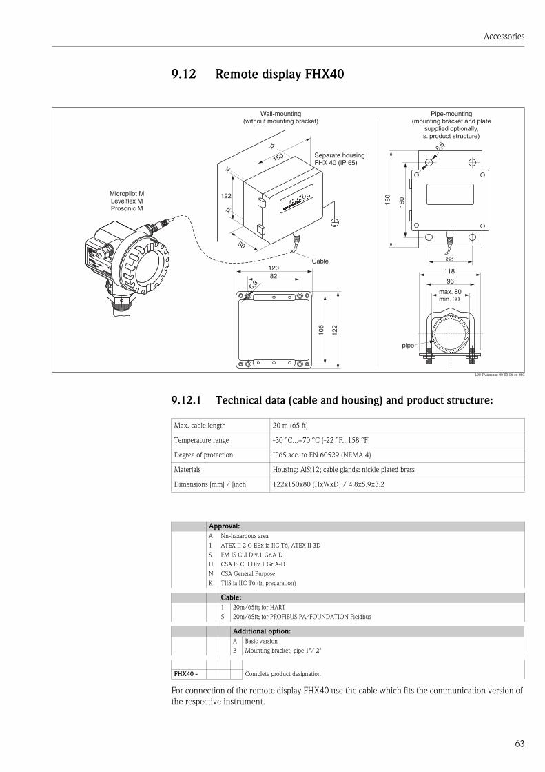
Accessories
63
9.12 Remote display FHX40
L00-FMxxxxxx-00-00-06-en-003
9.12.1 Technical data (cable and housing) and product structure:
For connection of the remote display FHX40 use the cable which fits the communication version of
the respective instrument.
ENDRESS+HAUSER
ENDRESS+HAUSER
IP 65IP 65
Order Code:Ser.-No.:
Order Code:Ser.-No.:
MessbereichMeasuring range
MessbereichMeasuring rangeU 16...36 V DC
4...20 mA
U 16...36 V DC4...20 mA
max. 20 m
max. 20 m
Made in
Germ
any
M
aulb
urg
Made in
Germ
any
M
aulb
urg
T>70°C :
A
t >85°C
T>70°C :
A
t >85°C 82
6,3
106
122
120
max. 80min. 30
96
88
160
8,5
118
180Micropilot M
Levelflex MProsonic M
Separate housingFHX 40 (IP 65)
Cable
122
150
80
Wall-mounting(without mounting bracket)
Pipe-mounting(mounting bracket and plate
supplied optionally,s. product structure)
pipe
Max. cable length 20 m (65 ft)
Temperature range -30 °C...+70 °C (-22 °F...158 °F)
Degree of protection IP65 acc. to EN 60529 (NEMA 4)
Materials Housing: AlSi12; cable glands: nickle plated brass
Dimensions [mm] / [inch] 122x150x80 (HxWxD) / 4.8x5.9x3.2
Approval:
A Nn-hazardous area
1 ATEX II 2 G EEx ia IIC T6, ATEX II 3D
S FM IS Cl.I Div.1 Gr.A-D
U CSA IS Cl.I Div.1 Gr.A-D
N CSA General Purpose
K TIIS ia IIC T6 (in preparation)
Cable:
1 20m/65ft; for HART
5 20m/65ft; for PROFIBUS PA/FOUNDATION Fieldbus
Additional option:
A Basic version
B Mounting bracket, pipe 1"/ 2"
FHX40 - Complete product designation

Technical Data
64
10 Technical Data
10.1 Technical data at a glance
10.1.1 Input
Measured variable The distance D between the sensor membrane and the product surface is measured.
Using the linearisation function, the device uses D to calculate:
• level L in any units
• volume V in any units
• flow Q across measuring weirs or open channels in any units
Maximum range/blocking
distance
1The actual range is dependent on the measuring conditions. Refer to Technical Information TI
365F/00/en for an estimation.
10.1.2 Output
Output signal 4 ... 20 mA with HART protocol
Signal on alarm • Error symbol, error code and plain text description on the on-site display
• Error code via HART communication
• Current output (configurable)
10.1.3 Auxiliary energy
Cable entry • Cable gland M20x1.5 (recommended cable diameter 6 ... 10 mm)
• Cable entry G½ or ½ NPT
Supply voltage • Loop-powered HART: 14 ... 36 V (depending on output current)
• Loop-powered fixed current: 10 ... 36 V
• 4-wire DC: 10.5 ... 32 VDC
• 4-wire AC: 90 ... 253 VAC
There may be additional restrictions for devices with an explosion protection certificate. Refer to the
notes in the appropriate safety instructions (XA).
Power consumption
Sensor Maximum range in liquids1 Maximum range in solids1 blocking distance
FMU 40 5 m 2 m 0,25 m
FMU 41 8 m 3,5 m 0,35 m
FMU 42 10 m 5 m 0,4 m
FMU 43 15 m 7 m 0,6 m
Version Power consumption
2-wire 51 mW ... 800 mW
4-wire AC max. 4VA
4-wire DC; FMU 40/41 330 mW ... 830 mW
4-wire DC; FMU 42/43 600 mW ... 1 W
Technical Data
65
Load HART Minimum load for HART communication: 250 Ω
HART ripple 47...125 Hz: Vpp = 200 mV (measured at 500 Ω)
Max. noise HART 500 Hz...10 kHz: Vrms = 2.2 mV (measured at 500 Ω)
Galvanic isolation With 4-wire devices, the evaluation electronics and mains voltage are galvanically isolated from
each other.
10.1.4 Performance characteristics
Reaction time The reaction time depends on the parameter settings (min. 0.5s for 4-wire devices,
min. 2s for 2-wire devices).
Reference operating
conditions
• Temperature = +20 °C
• Pressure = 1013 mbar abs.
• Humidity = 50 %
• Ideal reflective surface (e.g. calm, smooth fluid surface)
• No interference reflections within signal beam
• Set application parameters:
– Tank shape = flat ceiling
– Medium property = liquid
– process conditions = calm surface
Measured value resolution
Measuring error Typical specifications for reference operating conditions (include linearity, repeatability, and
hysteresis):
1whichever is greater
Sensor Measured value resolution
FMU 40 1 mm
FMU 41 1 mm
FMU 42 2 mm
FMU 43 2 mm
Sensor Measuring error
FMU 40 ±2mm or 0.2% of set measuring distance (empty calibration)1
FMU 41 ± 2 mm or 0,2% of set measuring distance (empty calibration)1
FMU 42 ± 4 mm or 0,2% of set measuring distance (empty calibration)1
FMU 43 ± 4 mm or 0,2% of set measuring distance (empty calibration)1

Technical Data
66
10.1.5 Ambient conditions
Ambient temperature -40 °C ... +80 °C
The functionality of the LC display becomes restricted at Tu<-20 °C and Tu>+60 °C.
If the device is operated outdoors in strong sunlight, you should use a protective cover.
Storage temperature -40 °C ... +80 °C
Climate class DIN EN 60068-2-38 (Test Z/AD) DIN/IEC 68 T2-30Db
Ingress protection • With closed housing, tested according to
– IP 68, NEMA 6P (24h at 1.83m under water surface)
– IP 66, NEMA 4x
• With open housing: IP 20, NEMA 1 (also ingress protection of the display)
Vibration resistance DIN EN 60068-2-64 / IEC 68-2-64: 20…2000 Hz, 1 (m/s2)2/Hz; 3 x 100 min
Electromagnetic compatibility
(EMC)
• Interference emission to EN 61326, Equipment Class B
• Interference immunity to EN 61326, Appendix A (Industrial) and NAMUR Recommendation NE
21 (EMC).
• A standard installation cable is sufficient if only the analogue signal is used. Use a screened cable
when working with a superimposed communication signal (HART).
10.1.6 Process conditions
Process temperature -40°C ... +80°C
A temperature sensor is integrated in the sensor for correction of the temperature-dependent time-
of-flight.
Process pressure • FMU 40/41: 0.7 bar ... 3bar abs.
• FMU 42/43: 0.7 bar ... 2.5bar abs.
! Note!
For pressures less than 0.7 bar please contact Endress+Hauser

Technical Data
67
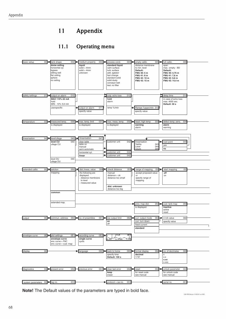
Appendix
68
11 Appendix
11.1 Operating menu
L00-FMU4xxxx-19-00-01-en-005
safety settings
basic setup
output on alarm
MAX 110% 22 mAholdMIN - 10% 3,6 mA
userspecific
tank shape
dome ceilinghorizontal cyl.bypassstilling wellflat ceilingsphereno ceiling
measured temp.
is displayed
level/ullage
level DUullage DU
level CUullage CU
selction
mapping
common
extended map.
commun. address
plot settings
envelope curveenv. curve + FACenv. curve + cust. map
present error
tag no.
output on alarm
specify value specify value
medium property
solid < 4mmsolid > 4mmunknown
liquid
max. temp. limit
is displayed
linearisation
table onmanualsemi-automatic
horizontal cyl.
linear
no. of preambles
recording curve
single curvecyclic
language
previous error
outp. echo loss
holdalarm
ramp %/min
process cond.
standard liquidcalm surfaceturb. surfaceadd. agitatorfast changestandard solidsolid dustyconveyor belttest: no filter
max. meas. temp.
is displayed
customer unitTabNoLevelvolum
customer unit
customer unit
low output limit
onoff
back to home
specify timeDefault: 100 s
clear last error
keeperase
protocol + sw-no.
Rampe %span/min
empty calibr.
distance membraneto min. levelDefault:FMU 40: 5 mFMU 41: 8 mFMU 42: 10 mFMU 43: 15 m
react. high temp
warningalarm
linearisation
pres. map dist.
is displayed
curr. output mode
curr. turn down
standard
fixed current
format display
decimal1/16”
reset
for reset codesee manual
Note! The Default values of the parameters are typed in bold face.
delay time
in case of echo lossmax. 4000 sec.Default: 30 s
full calibr.
spanmax.: empty - BDDefault:FMU 40: 4,75 mFMU 41: 7,6 mFMU 42: 9,6 mFMU 43: 14,4 m
defect temp. sens.
alarmwarning
next point
yes
no
cust. tank map
inactiveactivereset
4 mA value
specify value
no. of decimalas
xx.x
x.xxxx.xx
unlock parameter
for unlock codesee manual
serial no.
temperature
linearisation
extended calibr.
output
envelope curve
display
diagnostics
system parameters
01
00
010
002
030
040
040
040
050
060
0E1
0A0
0C0
011
003
031
041
061
0E2
092
0A1
012
004
032
042043044045
042
042
062
093
0A2
0C2
013
005
033
054
063
094
0A3
014
006
034
045
055
068
095
0A4
0C4
03
04
05
06
0E
09
0A
0C
clear table
dist./meas. value
the following aredisplayed:- distance membrane
to level- measured value
check distance
manualdistance = okdistance too small
distance too bigdist. unknown
range of mapping.
accept proposed valueorspecify range ofmapping
start mapping
offon
008 051 052 053
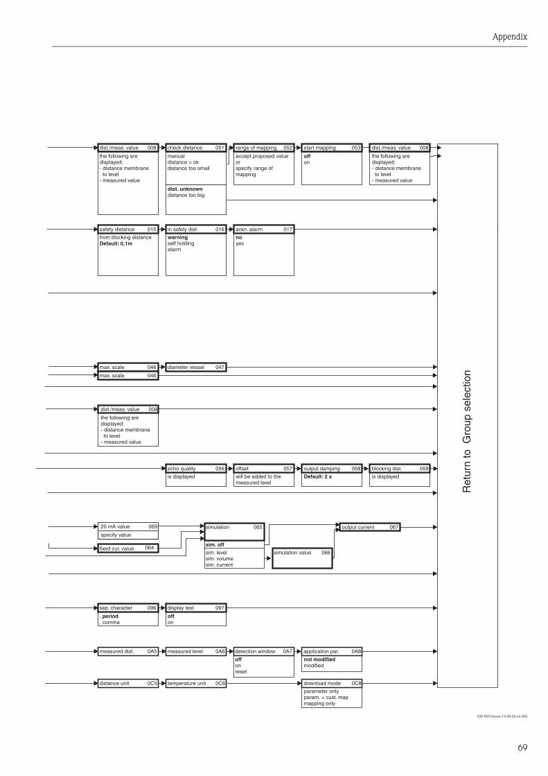
Appendix
69
L00-FMU4xxxx-19-00-02-en-005
simulation
sim. off
sim. levelsim. volumesim. current
sep. character
fixed cur. value
. period, comma
measured dist.
distance unit
max. scale
max. scale
safety distance
from blocking distanceDefault: 0,1m
dist./meas. value
the following aredisplayed:- distance membrane
to level- measured value
echo quality
is displayed
simulation value
display test
offon
measured level
temperature unit
diameter vessel
in safety dist.
warningself holdingalarm
check distance
manualdistance = okdistance too small
distance too bigdist. unknown
offset
will be added to themeasured level
output current
ackn. alarm
noyes
range of mapping.
accept proposed valueorspecify range ofmapping
output damping
Default: 2 s
application par.
Ret
urn
to G
roup
sel
ectio
n
not modifiedmodified
download mode
parameter onlyparam. + cust. mapmapping only
start mapping
offon
20 mA value
specify value
blocking dist.
is displayed
dist./meas. value
the following aredisplayed:- distance membrane
to level- measured value
065
096
064
0A5
0C5
046
046
015
008
056
066
097
0A6
0C6
047
016
051
057
067
017
052
058
0A8
0C8
053
069
059
008
dist./meas. value
the following aredisplayed:- distance membrane
to level- measured value
008
detection window
offonreset
0A7
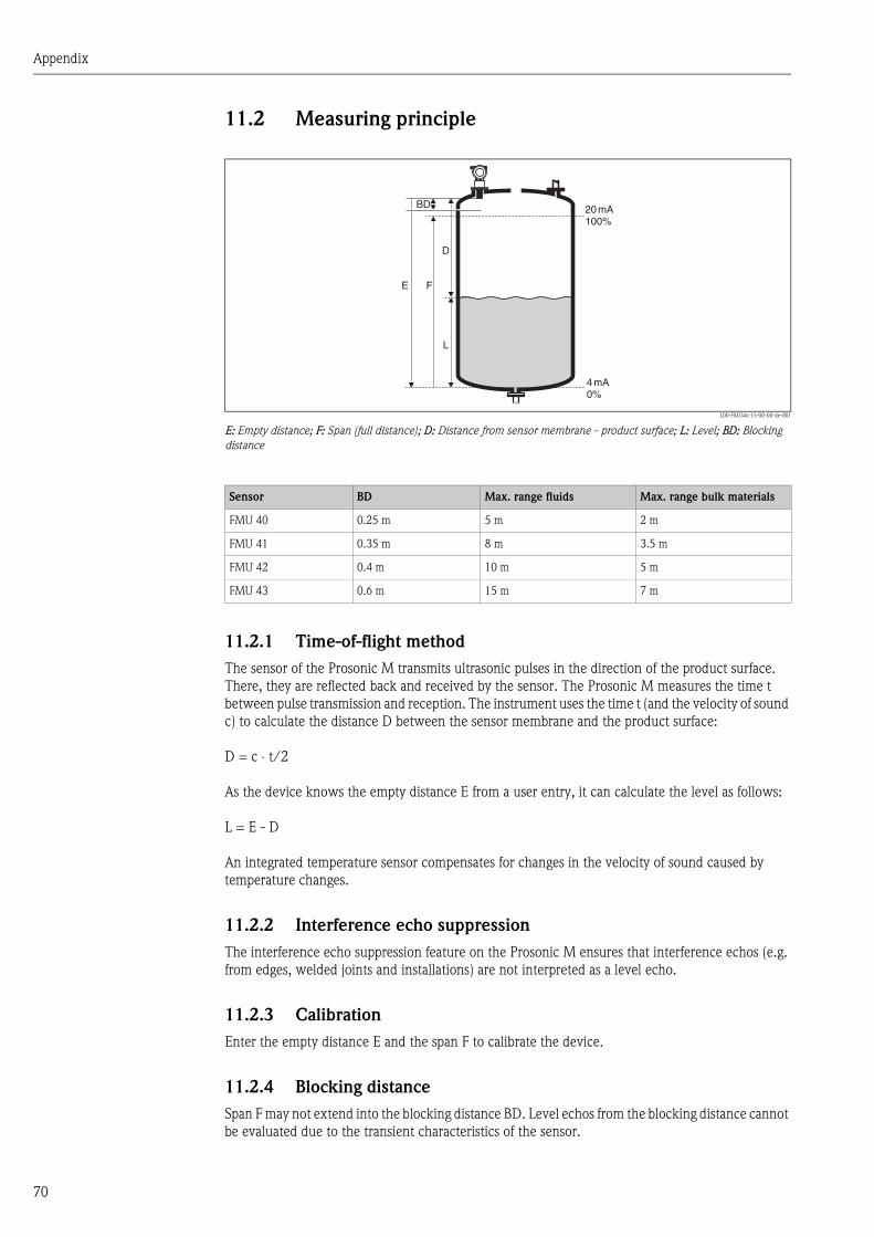
Appendix
70
11.2 Measuring principle
L00-FMU4x-15-00-00-de-001
E: Empty distance; F: Span (full distance); D: Distance from sensor membrane - product surface; L: Level; BD: Blocking
distance
11.2.1 Time-of-flight method
The sensor of the Prosonic M transmits ultrasonic pulses in the direction of the product surface.
There, they are reflected back and received by the sensor. The Prosonic M measures the time t
between pulse transmission and reception. The instrument uses the time t (and the velocity of sound
c) to calculate the distance D between the sensor membrane and the product surface:
D = c ⋅ t/2
As the device knows the empty distance E from a user entry, it can calculate the level as follows:
L = E - D
An integrated temperature sensor compensates for changes in the velocity of sound caused by
temperature changes.
11.2.2 Interference echo suppression
The interference echo suppression feature on the Prosonic M ensures that interference echos (e.g.
from edges, welded joints and installations) are not interpreted as a level echo.
11.2.3 Calibration
Enter the empty distance E and the span F to calibrate the device.
11.2.4 Blocking distance
Span F may not extend into the blocking distance BD. Level echos from the blocking distance cannot
be evaluated due to the transient characteristics of the sensor.
20mA100%
4mA0%
D
L
FE
BD
Sensor BD Max. range fluids Max. range bulk materials
FMU 40 0.25 m 5 m 2 m
FMU 41 0.35 m 8 m 3.5 m
FMU 42 0.4 m 10 m 5 m
FMU 43 0.6 m 15 m 7 m
Index
71
Index
Aalarm . . . . . . . . . . . . . . . . . . . . . . . . . . . . . . . . . . . . . . . . 45
application errors. . . . . . . . . . . . . . . . . . . . . . . . . . . . . . . . 47
Bblocking distance. . . . . . . . . . . . . . . . . . . . . . . . . . . . . 18, 39
Ccantilever . . . . . . . . . . . . . . . . . . . . . . . . . . . . . . . . . . . . . 59
CE mark . . . . . . . . . . . . . . . . . . . . . . . . . . . . . . . . . . . . . . 11
cleaning . . . . . . . . . . . . . . . . . . . . . . . . . . . . . . . . . . . . . . 49
Commubox. . . . . . . . . . . . . . . . . . . . . . . . . . . . . . . . . . . . 61
connection . . . . . . . . . . . . . . . . . . . . . . . . . . . . . . . . . . . . 21
Ddeclaration of conformity. . . . . . . . . . . . . . . . . . . . . . . . . . 11
declaration of contamination . . . . . . . . . . . . . . . . . . . . . . . 56
display appearance . . . . . . . . . . . . . . . . . . . . . . . . . . . . . . 26
display symbols . . . . . . . . . . . . . . . . . . . . . . . . . . . . . . . . . 26
Eerror codes . . . . . . . . . . . . . . . . . . . . . . . . . . . . . . . . . . . . 45
error messages . . . . . . . . . . . . . . . . . . . . . . . . . . . . . . . . . 45
FFHX40 . . . . . . . . . . . . . . . . . . . . . . . . . . . . . . . . . . . . . . . 63
flow measurements . . . . . . . . . . . . . . . . . . . . . . . . . . . . . . 16
full calibration . . . . . . . . . . . . . . . . . . . . . . . . . . . . . . . . . . 39
Hhardware security locking . . . . . . . . . . . . . . . . . . . . . . . . . 33
hazardous area . . . . . . . . . . . . . . . . . . . . . . . . . . . . . . . . . . 4
Iinstallation bracket . . . . . . . . . . . . . . . . . . . . . . . . . . . . . . 57
interference echo suppression . . . . . . . . . . . . . . . . . . . . . . 40
Kkey assignment . . . . . . . . . . . . . . . . . . . . . . . . . . . . . . . . . 27
Khafagi-Venturi flume . . . . . . . . . . . . . . . . . . . . . . . . . . . . 16
Llevel measurements. . . . . . . . . . . . . . . . . . . . . . . . . . . . . . 15
Mmeasuring principle . . . . . . . . . . . . . . . . . . . . . . . . . . . . . . 70
Measuring range . . . . . . . . . . . . . . . . . . . . . . . . . . . . . . . . 18
Nnozzle. . . . . . . . . . . . . . . . . . . . . . . . . . . . . . . . . . . . . . . . 18
Oon-site display . . . . . . . . . . . . . . . . . . . . . . . . . . . . . . . . . . 29
operating menu. . . . . . . . . . . . . . . . . . . . . . . . . . . . . . . . . 68
Pprocess conditions . . . . . . . . . . . . . . . . . . . . . . . . . . . . . . . 37
Rrange. . . . . . . . . . . . . . . . . . . . . . . . . . . . . . . . . . . . . . . . . 19
repairs to Ex-approved devices. . . . . . . . . . . . . . . . . . . . . . 49
return . . . . . . . . . . . . . . . . . . . . . . . . . . . . . . . . . . . . . . . . 56
SService Interface FXA291. . . . . . . . . . . . . . . . . . . . . . . 61–62
shafts. . . . . . . . . . . . . . . . . . . . . . . . . . . . . . . . . . . . . . . . . 15
software security locking . . . . . . . . . . . . . . . . . . . . . . . . . . 33
TToF Tool . . . . . . . . . . . . . . . . . . . . . . . . . . . . . . . . . . . . . . 30
turn housing . . . . . . . . . . . . . . . . . . . . . . . . . . . . . . . . . . . 20
Wwarning. . . . . . . . . . . . . . . . . . . . . . . . . . . . . . . . . . . . . . . 45
weather protection cover . . . . . . . . . . . . . . . . . . . . . . . . . . 57

Index
72
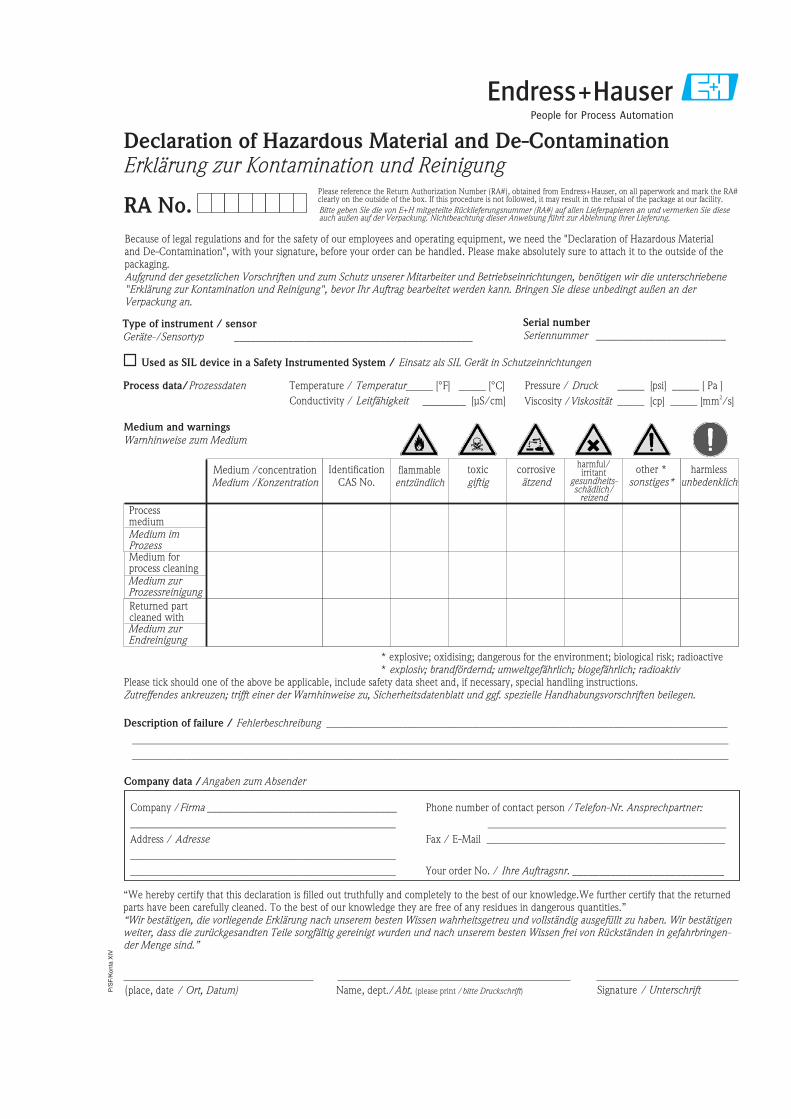
P/S
F/K
onta
XIV
Because of legal regulations and for the safety of our employees and operating equipment, we need the "Declaration of Hazardous Materialand De-Contamination", with your signature, before your order can be handled. Please make absolutely sure to attach it to the outside of thepackaging.Aufgrund der gesetzlichen Vorschriften und zum Schutz unserer Mitarbeiter und Betriebseinrichtungen, benötigen wir die unterschriebene"Erklärung zur Kontamination und Reinigung", bevor Ihr Auftrag bearbeitet werden kann. Bringen Sie diese unbedingt außen an derVerpackung an.
Serial number
Seriennummer ________________________Type of instrument / sensor
Geräte-/Sensortyp ____________________________________________
Process data/Prozessdaten Temperature _____ [°F] [°C]
Conductivity / ________
_____
Leitfähigkeit
/
[μS/cm]
Temperatur Pressure _____ [psi] [ Pa ]
Viscosity _____ [cp] [mm /s]
_____
_____
/
/
Druck
Viskosität2
corrosiveätzend
harmlessunbedenklich
other *sonstiges*
toxicgiftig
Processmedium
IdentificationCAS No.
flammableentzündlich
harmful/irritant
gesundheits-schädlich/
reizend
Medium /concentrationMedium /Konzentration
Returned partcleaned with
Medium forprocess cleaning
Medium and warnings
Warnhinweise zum Medium
* explosive; oxidising; dangerous for the environment; biological risk; radioactive* explosiv; brandfördernd; umweltgefährlich; biogefährlich; radioaktiv
Please tick should one of the above be applicable, include safety data sheet and, if necessary, special handling instructions.Zutreffendes ankreuzen; trifft einer der Warnhinweise zu, Sicherheitsdatenblatt und ggf. spezielle Handhabungsvorschriften beilegen.
Description of failure / Fehlerbeschreibung __________________________________________________________________________
______________________________________________________________________________________________________________
______________________________________________________________________________________________________________
“We hereby certify that this declaration is filled out truthfully and completely to the best of our knowledge.We further certify that the returnedparts have been carefully cleaned. To the best of our knowledge they are free of any residues in dangerous quantities.”“Wir bestätigenw
bestätigen, die vorliegende Erklärung nach unserem besten Wissen wahrheitsgetreu und vollständig ausgefüllt zu haben. Wireiter, dass die zurückgesandten Teile sorgfältig gereinigt wurden und nach unserem besten Wissen frei von Rückständen in gefahrbringen-
der Menge sind.”
(place, date / Ort, Datum)
Company data /Angaben zum Absender
Company / ________________________________
_________________________________________________
Address /
_________________________________________________
_________________________________________________
Firma ___
Adresse
Phone number of contact person /
____________________________________________
Fax / E-Mail ____________________________________________
Your order No. / ____________________________
Telefon-Nr. Ansprechpartner:
Ihre Auftragsnr.
Medium zurEndreinigung
Medium zurProzessreinigung
Medium imProzess
Used as SIL device in a Safety Instrumented System / Einsatz als SIL Gerät in Schutzeinrichtungen
RA No.
Erklärung zur Kontamination und ReinigungDeclaration of Hazardous Material and De-Contamination
Please reference the Return Authorization Number (RA#), obtained from Endress+Hauser, on all paperwork and mark the RA#clearly on the outside of the box. If this procedure is not followed, it may result in the refusal of the package at our facility.
Bitte geben Sie die von E+H mitgeteilte Rücklieferungsnummer (RA#) auf allen Lieferpapieren an und vermerken Sie dieseauch außen auf der Verpackung. Nichtbeachtung dieser Anweisung führt zur Ablehnung ihrer Lieferung.
Name, dept./Abt. (please print / )bitte Druckschrift Signature / Unterschrift

www.endress.com/worldwide
BA237F/00/en/08.06
CCS/FM+SGML 6.0/ProMoDo52010990


