
(Form: CE-014a-01)
HG-50/HG-80
OPERATING MANUAL
● Be sure to read this operation manual carefully and handle it properly.
WARNING !

-1-
Introduction
(1) No part of this document may be reproduced without permission.
(2) The contents of this document are subject to change without notice.
(3) This document has been carefully compiled. If you have any questions or require
information not covered in the manual, please contact :
���������� ���Hafing 21 84549 Engelsberg Tel.: +49 (0) 8634 625-994 Fax.:+49 (0) 8634 625 996 [email protected]
-2-
Read Carefully Before Using
● Determine the handling person responsible of this product.
● In this manual the following headings are applied to items to which great attention should be
given:
WARNING : Precaution indicating an imminent dangerous situation which if not avoided may lead to death or serious injury.
CAUTION : Precaution indicating a dangerous situation which if not avoided may lead to moderate or slight injury.
IMPORTANT : Indicates items you are strongly advised to obey.
NOTE : Items that will aid in proper operation of the equipment.
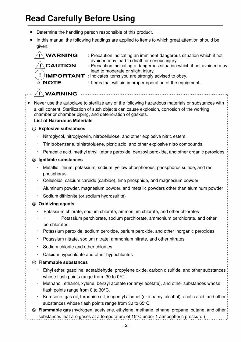
● Never use the autoclave to sterilize any of the following hazardous materials or substances with
alkali content. Sterilization of such objects can cause explosion, corrosion of the working chamber or chamber piping, and deterioration of gaskets.
List of Hazardous Materials
Explosive substances
・ Nitroglycol, nitroglycerin, nitrocellulose, and other explosive nitric esters.
・ Trinitrobenzene, trinitrotoluene, picric acid, and other explosive nitro compounds.
・ Peracetic acid, methyl ethyl ketone peroxide, benzoyl peroxide, and other organic peroxides.
Ignitable substances
・ Metallic lithium, potassium, sodium, yellow phosphorous, phosphorus sulfide, and red
phosphorus.
・ Celluloids, calcium carbide (carbide), lime phosphide, and magnesium powder
・ Aluminum powder, magnesium powder, and metallic powders other than aluminum powder
・ Sodium dithionite (or sodium hydrosulfite)
Oxidizing agents
・ Potassium chlorate, sodium chlorate, ammonium chlorate, and other chlorates
・ ・ Potassium perchlorate, sodium perchlorate, ammonium perchlorate, and other
perchlorates.
・ Potassium peroxide, sodium peroxide, barium peroxide, and other inorganic peroxides
・ Potassium nitrate, sodium nitrate, ammonium nitrate, and other nitrates
・ Sodium chlorite and other chlorites
・ Calcium hypochlorite and other hypochlorites
Flammable substances
・ Ethyl ether, gasoline, acetaldehyde, propylene oxide, carbon disulfide, and other substances
whose flash points range from -30 to 0°C.
・ Methanol, ethanol, xylene, benzyl acetate (or amyl acetate), and other substances whose
flash points range from 0 to 30°C.
・ Kerosene, gas oil, turpenine oil, isopentyl alcohol (or isoamyl alcohol), acetic acid, and other
substances whose flash points range from 30 to 65°C.
Flammable gas (hydrogen, acetylene, ethylene, methane, ethane, propane, butane, and other
substances that are gases at a temperature of 15°C under 1 atmospheric pressure.)
WARNING
!
!
!
!

-3-
● When liquid with salt water and much salinity of salt agar etc.
spills in the chamber, blowing, discharge water in the chamber and wipe up drop of water around the lid gasket beautifully. It causes the corrosion of the chamber and the piping when leaving just as it is
● Check that the pressure is below "0MPa" before opening the
lid.
● Absolutely do not attempt to remodel or alter this product.
● Foreign matter (metals, liquid) may enter through the vent hole. Operating the equipment with
such foreign matter inside may cause trouble with the equipment, fire or electric shock.
● Do not forcibly bend, twist, tie or extend the power cord. Do not place heavy objects on the cord.
A damaged cord or exposed wire can cause fire or electric shock.
● Never connect the power cord to a power supply other than one of the rated voltage. Connection
to such a power supply can cause fire or electric shock.
● If grounded socket is unavailable, ground the equipment using a separate ground wire before
connecting the power cord to the power source.
● Connect the grounding cable correctly to the Type D or higher-grade grounding terminal. Never
connect the grounding wire to gas pipes or water pipes.
● Close the lid after confirming that no foreign matter is adhering to the section contacting the lid
gasket. Foreign matter in this section can cause vapor leaks.
● When using a waste processing bag or other kind of bag and disinfecting, place the bag in the
metal mesh holder and then insert it into the chamber. Using the bag “as is” can cause excessive temperatures, pressures, lack-of-water, etc.
● Be careful not to pinch your hands when closing the lid.
● Do not touch the lid or lid cover when opening or closing the lid.
● Do not put your face or hands close to the chamber when lifting the lid after operations are
complete; steam will gush out of the chamber.
● The lid, chamber, gasket and panel are extremely hot immediately after the completion of
operation. Do not touch the equipment or you may get burned.
● Put on heat insulating gloves before removing a substance from the chamber. Do not put hands
into the chamber until the steam has been vented.
● Some time is required for liquids to cool. Be sure to check that the temperature has dropped
sufficiently before unloading a liquid from the chamber or burns can result.
● Do not unload the exhaust bottle or drain the chamber when the chamber is under pressure.
Boiling water or steam may gush out causing burns.
● Do not remove the exhaust bottle before water in the bottle has sufficiently cooled.
● If any abnormality occurs (e.g. abnormal sounds, smells, smoke), immediately shut the power off.
After checking to see that the abnormal condition does not continue, call our authorized distributor in your region.
● If the display reading changes between the steps, turn the POWER switch off then on again. If
the problem continues, turn the power switch off and call our authorized distributor in your region.
CAUTION !
0.2
0.3
0.40
0.1
0Pressuregauge

-4-
How to Read this Manual
● This operation manual consists of the following sections covering the information required for
proper operation of the Autoclave HG-50.
Chapter 1. What is the Autoclave HG-50? :
This section describes the uses and features of the product and the names and functions of its parts.
Chapter 2. Installation :
This section explains where the equipment should be installed and how to install it. The product incorporates precision parts, so be sure to follow the instructions covered in this chapter.
Chapter 3. Operation Method :
This section illustrates how to change various set values, and describes operations before starting the equipment and after automatic operation. This section also covers the display and performance of the equipment during automatic operation.
Chapter 4. Maintenance and Service :
This section explains the methods for draining water from the exhaust bottle or chamber, cleaning the body of the equipment, and parts replacement.
Chapter 5. Specifications
This section includes dimensions, power consumption and working range of the product. Refer to this section as is required.
Chapter 6. Troubleshooting
This section covers troubleshooting procedures for the product. If you encounter a problem, read this section first.
Appendix
This section contains information on the warranty and a glossary of terms that appear in the manual. Please refer to this section when necessary.

-5-
CONTENTS
Introduction··················································································································
Read Carefully Before User Inspection ····································································
How to Read this Manual ··························································································
CONTENTS ··················································································································
Chapter 1. What is the Autoclave HG-50? ·············································1 1. Product Uses··········································································································· 1
2. Product Features ····································································································· 1
3. Names and Functions of Each Part ········································································· 1
Chapter 2. Installation·············································································3 1. Installation Instructions ···························································································· 3
2. Installation Procedure······························································································ 4
Chapter 3. Operation Method ·································································6 Basic Operation Method ·························································································· 6
1. Power ······················································································································ 7
2. Pouring Water·········································································································· 7
3. Loading Substance·································································································· 8
4. Selection of Course and Program············································································ 9
5. Changing Set Values (Registering of Values by Customer) ··································· 11
6. Changing Function Setting ···················································································· 14
7. Reservation Operation··························································································· 16
8. Starting Operation·································································································· 18
9. Unloading ·············································································································· 19
10. After Completion of Operation ············································································· 19
11. To Interrupt Operation ·························································································· 20
12. If Power Supply is Cut Off during Operation ························································ 20
13. Operation of Cycles ····························································································· 20
Chapter 4. Maintenance and Service ···················································24 1. Draining Exhaust Bottle ························································································· 24
2. Draining Chamber ································································································· 25
3. Cleaning Chamber································································································· 25
4. Cleaning Body ······································································································· 26
5. Water Supply to Cooling Tank················································································ 26
Chapter 5. Specifications ·····································································27
Chapter 6. Troubleshooting ·································································28 1. Error Detection (Alarms) ······················································································ 28
2. Early Troubleshooting···························································································· 29
Appendix································································································30 1. Fast wearing parts ································································································· 30
2. Glossary ················································································································ 30
3. Limited Warranty ··································································································· 31

-6-
Chapter 1. What is the Autoclave HG-50?
1. Product Uses ・ The product is used to sterilize substances which can withstand high temperature and high
pressure steam such as tools of glass, ceramic, metal or rubber, water, media, reagents and liquid medicines (Mode 1 – 3) .
・ The product is also used to liquefy media (Mode 4).
2. Product Features ・ In order to secure safety, the product is provided with a lid cover around the section that
becomes hot during operation,.
・ The lid of the product is opened and closed automatically. It is not necessary to bring your
hands near the chamber port to open or close the lid. The safety has been improved this way.
・ The agar cycle, which prevents solidification of sterilized media when they are not taken out
immediately, and the dissolution cycle, which dissolves solidified media, are provided.
・ When the exhaust valve (the opening of the exhaust valve) is set, fine exhaust is conducted
automatically after sterilization.
・ Steam that comes out of the exhaust valve during air release and exhaust is cooled in the
cooling tank to minimize the quantity of steam that is emitted into the room.
・ The temperature, at which the loaded substance cannot be taken out, can be set for safety within
the range of 60-97℃ for each cycle and program number.
・ A reservation timer is provided to permit operation startup at any desired time within the range of
1 hour to 99 hours later.
3. Names and Functions of Each Part
●●●● Outer View of Body
F. L
Lid cover
Operation panel
Pressure gauge
Drain bottle
Drain valve
Caster
Vent hole
Power cord
Main power switch
Cooling fan
Vent hole
Cooling tankWater filler port
Lid
Gasket
Chamber
0.2
0.3
0.40
0.1
Top panel
Top View
Front View Right Side View Rear View
When the lid is open

-7-
●●●● Operation panel
Digital Display (Temperature) The digital display indicates the sterilization set time in the standby state, and it indicates the chamber temperature during operation.
Digital Display (Time and Pressure) The digital display indicates the set time, reservation time, etc. in the standby state, and it indicates the pressure inside the chamber, time remaining until completion of sterilization, and time remaining until completion of warming during operation.
Digital Display (Warming) The digital display indicates the warming set temperature, function number, etc. in the standby state, and it indicates the error when it is detected.
Unit Display ( , , , and ) The unit corresponding to the current digital display illuminates.
State Display ( , , and ) The state display indicates the present state.
Cycle Display The action cycle of the preset cycle illuminates, and the current cycle blinks.
Drain Bottle Display The red light blinks when the drain bottle is full, and the green light illuminates when it is not full.
POWER Switch Used to turn on or off the power to the autoclave.
LID CLOSE Switch Used to close the lid.
LID OPEN switch Used to open the lid. When the lid can be opened, a green light comes on, and when the lid cannot be opened because the chamber is hot and highly pressurized, a red light comes on.
Cycle Switch Used to select the cycle and program number.
FUNC. Switch Used to change and confirm the setting of respective functions.
SET switch Used to change and confirm the set value.
Set Value Increase/Decrease Switch ( ) Used to increase or decrease the set value.
Exhaust Level Switch (� �) Used to change the exhaust level.
FAN Cooling ON/OFF Switch Used to change fan cooling ON/OFF setting.
START Switch Used to start operation.
STOP Switch Used to stop operation.
PROGM Display The display indicates the present program.
LIDCLOSESTERI/DISSOL
HEAT
FAN
F UNC.S ET
PROGM1
WARM
EXHT.
EXHT.
POWER
TEMP
2 3
℃
AGA RL IQ .
SOL IDDISS O L
MPa
Hr/min.
DRAIN BOTTLE
℃
START
STOP
LIDOPEN
ONOFF

-8-
Chapter 2. Installation
● If the equipment is installed in a place which is 800m or higher than sea level (i.e. under low
pressure in mountainous areas), the settings must be changed. In this case, be sure to contact our authorized distributor in your region. Do not use the equipment before changing.
● When relocating the product, close the lid so that it will not move, and then remove the drain
bottle and power cord.
1. Installation instructions
Avoid installing the equipment in a place where its
body may be exposed to water or chemicals, or
where corrosive and explosive gases may be
produced neareby.
Avoid placing the equipment directly under a fire
detector. If you open the lid immediately after
completion of operation, steam comes out of the
working chamber, and may activate the detector.
Arrange the equipment with a clearance of 10 cm
or wider on the right side and 12 cm or wider on
the rear side to prevent the vent hole from
being blocked.
10cm or more
Avoid an installation place which is subject to impact
or vibration.
Place the unit in a level, firm place.
Avoid installing in a place which is subjected to a room
temperature of 5 ℃ or below or 35 ℃ or above.
Avoid installing the equiopment in a place which is
exposed to hight humidity, direct sunlight or much
dust.
0.2
0.3
0. 40
0. 10.2
0.3
0. 40
0. 1
0. 2
0.3
0. 40
0. 1
10cm or more
12cm or more
IMPORTANT !

-9-
2. Installation Procedure
Pour water into the cooling tank.
・ Remove the cap from the water filler port at the
back of the unit, and pour water through the water filler port by using a hose, etc. up to the center of the level confirmation window at the side of the unit. After water supply, return the cap back to the original position. (Hoses, etc. are not provided. Please prepare them by yourself.)
Put casters on the caster stoppers so that the
unit will not move.
・ Place two casters at a position more than 64 cm
away from the wall, and push the unit so that the front casters will be on the stoppers.
・ Be sure to set the caster stoppers, otherwise the
full water function of the drain bottle may not be activated.
Connect the power cord to the rated power supply.
・ Be sure to connect the grounding wire.
● Do not forcibly bend, twist, tie, or extend the power cord. Do not place heavy objects on the cord.
A damaged cord or exposed wire may cause fire or electric shock.
● Never connect the power cord to a power supply with a voltage other than the rated voltage.
Connection to such a power supply may cause fire or electric shock.
● If not plugging the sterilizer into a grounded socket, ground the equipment separately before
connecting it to the power source.
● Never ground to a gas pipe or vinyl chloride water service pipe.
・ Connect the unit to a power unit of as below and to ground the Green/Yellow grounding wires.
・ AC100V: 20Amp or more, AC110V: 19Amp or more, AC120V: 17Amp or more,
・ AC220V: 10Amp or more, AC230 and AC240V : 9Amp or more.
CONNECT TO RATED VOLTAGE
Black
White
Green/Yellow
Connect
to ground
Water filler port
Cap
Center
Wa ter leve l check
window
64 cm or more
Caster stopper
CAUTION !

-10-
Turn ON the main power switch.
・ Raise the lever of the main power switch at the right side of the unit.
Raise.
Main power switch
Referring to “Chapter 3, Operation Method”, open the lid and take out the accessories.
Place the bottom plate in the chamber.
Attach the drain bottle.
・ Check that there is no foreign substance or irregularity on the floor where the drain bottle is
to be set.
Drain bottle
-11-
Chapter 3. Operation Method
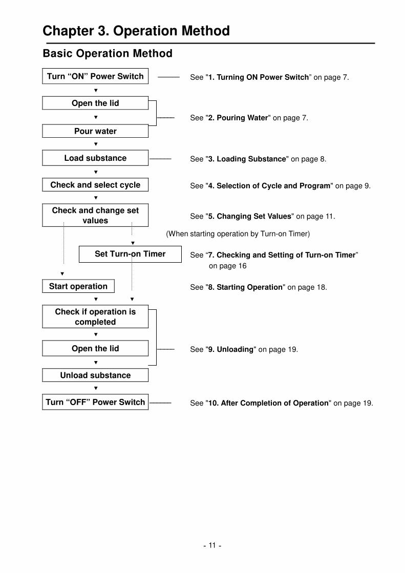
Basic Operation Method
Turn “ON” Power Switch ―――――― See "1. Turning ON Power Switch” on page 7.
Open the lid
――――― See "2. Pouring Water" on page 7.
Pour water
Load substance ―――――― See "3. Loading Substance" on page 8.
Check and select cycle See "4. Selection of Cycle and Program" on page 9.
Check and change set
values See "5. Changing Set Values" on page 11.
(When starting operation by Turn-on Timer)
See “7. Checking and Setting of Turn-on Timer”
on page 16
Start operation See "8. Starting Operation" on page 18.
Check if operation is
completed
Open the lid ――――― See "9. Unloading" on page 19.
Unload substance
Turn “OFF” Power Switch ―――――― See "10. After Completion of Operation" on page 19.
Set Turn-on Timer
-12-
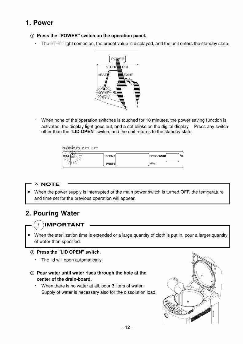
1. Power
Press the "POWER" switch on the operation panel.
・ The light comes on, the preset value is displayed, and the unit enters the standby state.
・ When none of the operation switches is touched for 10 minutes, the power saving function is
activated, the display light goes out, and a dot blinks on the digital display. Press any switch other than the "LID OPEN" switch, and the unit returns to the standby state.
● When the power supply is interrupted or the main power switch is turned OFF, the temperature
and time set for the previous operation will appear.
2. Pouring Water
● When the sterilization time is extended or a large quantity of cloth is put in, pour a larger quantity
of water than specified.
Press the "LID OPEN" switch.
・ The lid will open automatically.
Pour water until water rises through the hole at the
center of the drain-board.
・ When there is no water at all, pour 3 liters of water.
Supply of water is necessary also for the dissolution load.
NOTE
IMPORTANT !
STERI/DISSOL
HEAT EXHT.
POWER
PROGM1
TEMP
2 3
℃
MPa
Hr/min.

-13-
3. Loading Substance
● Be careful not to pinch hands when closing the lid.
● Close the lid after confirming that no foreign matter is adhering to the section contacting the lid
gasket. Foreign matter in this section may cause vapor leaks.
● When using a waste processing bag or other kind of bag and disinfecting, place the bag in the
metal mesh holder and insert it into the working chamber. Using the bag “as is” can cause excessive temperatures, pressures, lack-of -water, etc.
● Be sure to use the drain-board.
● The section of the inlet of the chamber, which is to be in contact with the gasket, is important for
gas sealing. Exercise care so as not to damage the section by hitting it with a loaded substrate.
● Do not put in any substance larger than the inner dimensions of the chamber.
Put a substance (dissolved material)
in the chamber.
● When sterilizing an empty deep container, lay the container on its side in the chamber so that it
will be permeated with steam. An upright position may cause insufficient sterilization.
● If a waste disposal bag is used in sterilization, open the bag far enough that the bag is not in
contact with the inside surface of the chamber. Insufficient sterilization may be caused if the bag is closed during sterilization. When the bag is opened excessively, steam is prevented from circulating in the chamber. This may also result in insufficient sterilization.
● Do not pile specimens on top of one another. When the chamber is overly packed, steam fails to
penetrate to all points, resulting in incomplete sterilization.
● In sterilizing liquids such as chemicals and media, pay attention to the quantity of the liquid in
relation to its container. For an Erlenmeyer flask, the amount of chemical should be approx. 3/4 of the capacity of the container; for a test tube, the appropriate quantity of chemical is approx. half of the capacity of the container. Too much chemical may result in overflow from the container during the temperature rising or cooling process.
● Use container caps that are loose fitting and allow the passage of air. Containers may break if
venting is not possible.
● In the case of dissolution of agar media, its quantity should be 2 liters or less per container.
Two liters or more of agar medium may not be completely dissolved.
● Use the DURHAM TEST TUBE (Sample tube) with 6mm caliber or more. At the DURHAM TEST
TUBE (Sample tube) with less than 6 mm caliber, air bubble sometimes remains. Delaying of air release time may allow no air bubbles to be left. Change the air release time, referring to “6. Changing Function Setting.”
CAUTION
IMPORTANT
NOTE
!
!

-14-
4. Selection of Cycle and Program
● Select a cycle according to the usage.
Press the cycle switch (LIQ., AGAR, SOLID, or
DISSOL).
・ Every time the switch is pressed, the program
changes 2, 3, 1, ... repeatedly.
Cycle Application
Liquid Sterilization of water, media, solid reagent, liquid reagent, liquid chemical, and other liquid that can withstand high-temperature high-pressure steam.
Agar Sterilization of agar media (to be warmed so that it will not solidify after sterilization)
Solid Sterilization of glass, ceramics, metal, rubber, and other solid equipment that can withstand high-temperature high-pressure steam and sudden decompression during exhaust
Dissolution Dissolution of media
Initial set value (for all 3 programs) Display of cycle Sterilizati
on temp. Sterilization time
Exhaust level
Fan cooling
Warming temp.
HEAT → STERI →
EXHT./COOL 121℃ 20 min. 0 OFF
Liquid cycle STERI/DISSOL
HEAT
FAN
PROGM1
WARM
EXHT.
EXHT.
TEMP
2 3
℃
AG A RL IQ .
S OLIDDIS SO L
MPa
Hr/min.
ONOFF
Initial set value (for all 3 programs) Display of cycle Sterilizati
on temp. Sterilization time
Exhaust level
Fan cooling
Warming temp.
HEAT → STERI → EXHT./ COOL → WARM
121℃ 20 min. 0 OFF 50℃
Agar cycle STERI/DISSOL
HEAT
FAN
PROGM1
WARM
EXHT.
EXHT.
TEMP
2 3
℃
AG A RL IQ .
S OLIDDISS O L
MPa
Hr/min.
ONOFF
AG A RLIQ.
SOLIDDISSO L
-15-
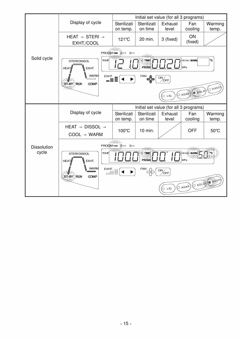
Initial set value (for all 3 programs) Display of cycle Sterilizati
on temp. Sterilization time
Exhaust level
Fan cooling
Warming temp.
HEAT → STERI →
EXHT./COOL 121℃ 20 min. 3 (fixed)
ON (fixed)
Solid cycle STERI/DISSOL
HEAT
FAN
PROGM1
WARM
EXHT.
EXHT.
TEMP
2 3
℃
AGA RL IQ .
SOL IDDISSO L
MPa
Hr/min.
ONOFF
Initial set value (for all 3 programs) Display of cycle Sterilizati
on temp. Sterilization time
Exhaust level
Fan cooling
Warming temp.
HEAT → DISSOL →
COOL → WARM 100℃ 10 min. OFF 50℃
Dissolution cycle STERI/DISSOL
HEAT
FAN
PROGM1
WARM
EXHT.
EXHT.
TEMP
2 3
℃
AGA RL IQ .
SOL IDDISSO L
MPa
Hr/min.
ONOFF

-16-
5. Changing Set Values (Registering of Values by Customer)
● When power supply is interrupted or the main power switch is turned OFF before operation with
the preset temperature and time, the preset values will return to the original values.
Select the cycle for which the setting is to be changed, select the program number under which the set values are to be saved, and then change the setting as shown below.
● Sterilization temperature, sterilization time, warming temperature, dissolution
temperature, and dissolution time
Set values cannot be changed during operation.
Press the "SET" switch.
・ The sterilization (dissolution) set temperature
display blinks, permitting setting change.
When changing the setting other than the
sterilization (dissolution) temperature, press the "SET" switch further and select the setting item to change.
・ Every time the switch is pressed, the changeable setting items change repeatedly as shown
below.
Switch input
Liquid cycle Sterilization temperature
Sterilization
time
Agar cycle Sterilization temperature
Sterilization
time
Warming temperature
Solid cycle Sterilization temperature
Sterilization
time
Dissolution
cycle
Dissolution temperature
Dissolution
time
Warming temperature
Press the set value increase/decrease switch ( ) to change the value.
・ Every time the switch is pressed:
The stylization temperature increases or decreases within the range of 5-135℃ at every ℃.
The sterilization time increases or decreases within the range of 1 min.-5 hr at every minute.
The dissolution temperature increases or decreases within the range of 60-100℃ at every ℃.
The dissolution time increases or decreases within the range of 1 min.-1 hr at every minute.
The warming temperature increases or decreases within the range of 45-60℃ at every ℃.
・ Keep pressing the switch, and the value increases at the rate of 10 units, returning to the
lower (upper) limit when the value exceeds the upper (lower) limit.
Leave the switch untouched for 5 seconds, and the blinking display will remain lit,
completing the setting.
NOTE
SET SET SET
FAN
FU NC.SET
PROGM1
EXHT.
TEMP
2 3
℃
MPa
Hr/min.
ONOFF

-17-
● For sterilization of liquid, set a sterilization time longer than desired, taking delay time into
account and referring to the table below. �������� In case there is 3 liters of water in a flask, it takes nearly 30 minutes (delay time) for
temperature of water in the container to reach a set sterilization temperature after temperature in the chamber reaches the set value. You should set a sterilization time 30 minutes longer than desired to cope with this delay of time. Therefore, the set sterilization is 50 minutes:
Set sterilization time (50 minutes) = Delay time (30 minutes) + desired sterilization time (20 minutes)
HG-50 Reference Values of Delay Time (per Flask)
Liquid Volume Delay Time 3 liters 30 minutes 2 liters 25 minutes 1 liter 20 minutes 500 cc 15 minutes
● If steam is abruptly exhausted after sterilization
of liquid, the liquid may gush out. To prevent this, set the opening of the exhaust valve (Exhaust % ) to a small value to gradually exhaust. Or, set that to 0 % (natural cooling).
● When used with a sterilization can, it takes
several hours for the temperature in waste disposal bag to reach the set temperature after the temperature in the chamber (displayed temperature) reaches the set value (time lag). If there is approx. 300 ~ 500 milliliters of water in the waste disposal bag, steam is generated in the bag and drives the air out. This will significantly reduce the time lag at the time of temperature rise. Refer to the table below and take this time lag into account when setting the fertilization time. The delay time will be shortened when a perforated sterilization can is used.
HG-50 Reference Values for Time Lag in Bag
Water in Bag Time Lag Not poured 206 minutes
Poured 48 minutes
Model: HG-50
Case: A large number of φ15 x 100 test tubes
placed in a waste disposal bag.
● For dissolution of coagulated agar medium, set an appropriate dissolution temperature and time,
referring to the table below.
HG-50 Reference Values (per Flask)
Quantity of Liquid Dissolution Temperature Dissolution Time 2 liters 60 minutes 1 liter 45 minutes 500 cc
100℃ 25 minutes
NOTE
40
60
80
100
120
1 20
(Temperature)
(Time)
S et sterilizat ion time
Delay time Sterilizat ion time
Temperature of water
Temperature
HG- 50 Delay Time Reference Data
in 3 liter container
temp.
Room in working chamber

-18-
● Exhaust level
The exhaust level can be changed from level 0 to level 3 in the liquid and agar cycles. It can be changed also during operation.
Press the "����" switch to increase the exhaust level, and press the "����" switch to decrease
the level.
EXHT.
● Sudden exhaust after sterilization of liquid may cause the liquid to spill. Set a lower exhaust
level for fine exhaust, or set the level 0 (natural cooling).
● Continuous operation at the exhaust level of 3 may cause steam to come out of the exhaust port
of the drain bottle. In that case, lower the exhaust level, except for the solid cycle, and turn ON the fan cooling function.
● Fan cooling ON/OFF
Except the solid cycle, fan cooling ON/OFF can be changed. It can be changed also during operation.
Press the "Fan cooling ON/OFF" switch.
・ When the fan display remains lit, the fan begins to rotate after sterilization.
FAN
FF
NOTE

-19-
6. Changing Function Setting
● When power supply is interrupted or the main power switch is turned OFF before operation with
the preset temperature and time, the preset values will return to the original values.
Select the cycle for which the setting is to be changed, select the program number under which the set values are to be saved, and then change the setting as shown below.
● Air release time
The initial setting for air release is set at 4 min. after 97℃ detection. If air bubbles remain in a
Durham tube and the like of less than 6 mm in inner diameter, extension of the air release time may eliminate remaining air bubbles. Extension of the air release time may eliminate remaining air bubbles also when a large quantity of cloth is put in the chamber. The time can be set for each cycle and program number. The set value cannot be changed during operation.
Press the "FUNC." switch two times in the standby state.
・ "F2" will appear on the digital display, and the air release set time display will blink, entering
the changeable state.
FAN
FU NC.SE T
PROGM1
EXHT.
TEMP
2 3
℃
MPa
Hr/min.
ONOFF
Press the set value increase/decrease switch ( ) to change the value.
・ Every time the switch is pressed, the time increases (decreases) within the range of 3-9 min.
at every minute.
・ When the set value exceeds the upper (lower) limit, it will return to the lower (upper) limit.
Leave the switch untouched for 5 seconds, and the display will return to the standby
state, completing the setting.
NOTE

-20-
● Lid lock temperature
The temperature that prevents the loaded substance from being taken out for safety can be set
for each cycle and program number. The initial setting of the lid lock is 80℃ for the liquid, agar,
and dissolution cycles, while it is 97℃ for the solid cycle.
The set value cannot be changed during operation.
● The center temperature of liquid will take much time to lower. Take the delay in temperature
drop into sufficient consideration when setting the lid lock temperature in order to avoid an accidental scald.
Press the "FUNC." switch three times in the standby state.
・ "F3" will appear on the digital display, and the lid lock set temperature display will blink,
entering the changeable state.
FAN
F UNC.S E T
PROGM1
EXHT.
TEMP
2 3
℃
MPa
Hr/min.
ONOFF
Press the set value increase/decrease switch ( ) to change the value.
・ Every time the switch is pressed, the temperature increases (decreases) within the range of
60-97℃ at every ℃.
・ When the set value exceeds the upper (lower) limit, it will return to the lower (upper) limit.
Leave the switch untouched for 5 seconds, and the display will return to the standby
state, completing the setting.
CAUTION !

-21-
7. Reservation Operation
● After the preset time passes, operation is started automatically.
Press the "FUNC." switch once in the
standby state.
・ "F1" will appear on the digital display,
and the reservation time display will blink, entering the changeable state.
・ When the switch remains untouched for
5 seconds during reservation time setting, the reservation is cancelled, returning to the standby state.
Press the set value increase/decrease
switch ( ) to change the value.
・ Every time the switch is pressed, the
time increases (decreases) within the range of 1-99 hr at every hour.
・ When the switch remains pressed continuously, the time will increase (decrease) at every 10
hours, and when the set value exceeds the upper (lower) limit, it will return to the lower (upper) limit.
Press the "START" switch.
● Exercise care so as not to be caught in the lid when it closes.
● Do not touch the lid or lid cover when opening/closing the lid.
● Check that there is no foreign substance in the section, which is in contact with the gasket, before
operation. Such a foreign substance will cause steam leakage.
・ Press the "START" switch within 5 seconds after pressing the last set value increase/decrease
switch.
・ The lid will close automatically, the reservation timer remaining time will be shown on the
digital display, and display will illuminate.
・ When operation will not begin even if the "START" switch is pressed, check to see if the drain
bottle is full of water. If it is full, refer to "1. Draining Exhaust Bottle" on page 24. Operation will not begin either when the lid has not been opened or closed completely. Press the "LID OPEN" switch, and press the “START” switch again after the lid has opened completely.
CAUTION
FAN
FUN C.SE T
PROGM1
EXHT.
TEMP
2 3
℃
MPa
Hr/min.
ONOFF
!

-22-
LIDCLOSESTERI/DISSOL
ST- BY
HEAT P RES S
TI ME
FAN
RUN COMP.
FUNC .S E T
PROGM1
WARM
EXHT.
EXHT.
POWER
TEMP
2 3
℃
AG ARL IQ.
SO LIDDIS SO L
MPa
Hr/min.
DRAIN BOTTLE
WARM ℃
START
STOP
LIDOPEN
ONOFF
● Press the "FUNC." switch to confirm the preset reservation time during the reservation timer
cycle. The set time will be displayed for 5 seconds. The set reservation time cannot be changed.
● The set reservation time will be 0 hr after the reservation timer cycle.
● The set reservation time is valid only for one operation.
Confirmation of reservation time during reservation timer operation cycle
NOTE

-23-
8. Starting Operation
Press the "START" switch.
・ The lid will close automatically, the display will illuminate, and the cycles
shown below will begin automatically according to the selected cycle. Refer to "13. Operation of Cycle" on page 20 for the details of the operation of each cycle.
・ When operation will not begin even if the "START" switch is pressed, check to see if
the drain bottle is full of water. If it is full, refer to "1. Draining Exhaust Bottle" on page 24. Operation will not begin either when the lid has not been opened or closed completely. Press the "LID OPEN" switch, and press the “START” switch again after the lid has opened completely.
● Exercise care so as not to be caught in the lid when it closes.
● Do not touch the lid or lid cover when opening/closing the lid. ● Check that there is no foreign substance in the section, which is in contact with the gasket, before
operation. Such a foreign substance will cause steam leakage.
Liquid cycle Agar cycle Solid cycle Dissolution
cycle
Lid open
Reservation timer operation
Air release
Heating Heating
Sterilization Dissolution
Exhaust/cooling
Cooling
Warming Warming
Completion
● When the lid is closed while the temperature inside the chamber is still high, the air in the
chamber leaking through the gasket will make a hissing sound, which is not failure. Continue operation.
● To confirm the set temperature and time during operation, press the "SET" switch. While the
switch is being pressed, the set value is displayed. The set value cannot be changed.
START
CAUTION
NOTE
Confirmation of setting during operation
!

-24-
9. Unloading
● When salt water, salt media, and other liquid with a high
concentration of salt boil over inside the chamber, drain water from the chamber and wipe the area around the gasket cleanly, otherwise the chamber and piping will be corroded, causing explosion.
● Confirm that the gauge for pressure in the chamber reads "0MPa".
● Keep the face and hands away from the chamber when lifting the lid after operations are
complete; steam will gush out of the opening of the chamber. ● After operation is over, the lid, chamber, packing and panel are hot. To protect yourself from
burns, do not touch with bare hands. ● It takes a lot of time for the liquid to cool. Be sure to check that the temperature has dropped
sufficiently before unloading the liquid from the chamber, or you may get burned. ● Put on heat insulation gloves before taking a substance out of the chamber.
Do not put your hands into the chamber until the steam has been vented.
Press the "LID OPEN" switch.
・ When the display is red, the lid cannot be opened.
Take out the loaded substance.
Press the "LID CLOSE" switch.
・ When the temperature inside the chamber is high, the cooling fan will run until the temperature drops to permit safe locking of the lid. The air leaking from the chamber will make a hissing sound, which is not failure. Continue operation.
・ Lid will not be closed just in case the lid is not opened completely. Press “LID OPEN” switch and press the “LID CLOSE” switch again after the Lid has been opened completely.
10. After Completion of Operations
Turn off the POWER switch after the completion of each routine operation.
● To prevent clogging of the piping, change water within the chamber once daily, referring to
"2. Draining Chamber" on page 25.
● The temperature and time set for the previous operation are saved even if the power supply is
interrupted or the main power switch is turned OFF.
WARNING
�������������
0.2
0.3
0.40
0.1
0
CAUTION
IMPORTANT
NOTE
!
!
!

-25-
11. To Interrupt Operation
Press the "STOP" switch.
・ The automatic cycle is interrupted, and the unit enters the standby state (the
state before operation).
・ Refer to "9. Unloading" when taking out the loaded substance. (The lid will
not open until the temperature inside the chamber drops below the lid lock temperature and the pressure drops to 0 MPa.)
12. If Power Supply is Cut Off during Operation
● When the power supply is stopped because of power failure and the like, the operation will be
interrupted. After power supply is resumed, the power will be in the "OFF" state. Press the "POWER" switch to enter the standby state, and the display will blink. Restart the operation. The display will blink also when the "POWER" switch is pressed during operation to turn off the power supply.
13. Operation of Cycles
Display of cycle
■ Lid closing cycle …… Common to all cycles
・ The chamber temperature and pressure are shown on the digital display, and the lid closes
automatically.
・ When temperature inside the chamber is high, the cooling fan runs until the temperature
drops, permitting safe lid locking. ■ Reservation timer operation cycle …… Common to all cycles (during reservation operation)
・ The remaining time in the reservation timer is shown on the digital display.
■ Air release cycle …… Liquid cycle, agar cycle, and solid cycle
・ The illuminated air release section on the cycle display changes to blinking, and the
temperature and pressure inside the chamber begin to be shown on the digital display.
・ Air releasing will continue after the temperature inside the chamber reaches 97℃ until the
reset air release time passes. ■ Heating cycle …… Liquid cycle, agar cycle, and solid cycle
・ The illuminated heating section of the cycle display changes to blinking.
・ Temperate continues to rise until the exhaust valve closes and the temperature (pressure)
reaches the preset sterilization temperature (pressure).
STOP
Sterilization cycle Dissolution cycle
Heating cycle
Warming cycle
Exhaust/cooling cycle
Air releasecycle
Cooling cycle

-26-
■ Heating cycle …… Dissolution cycle
・ The illuminated air release section on the cycle display changes to blinking, and the
temperature and pressure inside the chamber begin to be shown on the digital display.
・ The temperature continues to rise until it reaches the preset dissolution temperature.
■ Sterilization cycle …… Liquid cycle, agar cycle, and solid cycle
・ The illuminated sterilization section of the cycle display changes to blinking, and the
sterilization set time appears on the digital display simultaneously with the sterilization timer operation.
・ The temperature (pressure) is kept constant during the preset sterilization time.
・ When the temperature inside the chamber increases or decreases by "0.1℃" or more from the
set value because of an error, the overcool mark on the digital display illuminates, and the sterilization timer stops operation. Operation is resumed when the temperature reaches the set temperature again.
Overcool mark
℃ Hr/min.
Blinking stops.
TEMP
・ The digital timer shows the remaining time during the sterilization cycle. Press the "SET"
switch to confirm the preset time. While the switch is being pressed, the set value is displayed. The set value cannot be changed.
● In sterilization of petri dishes or empty containers, the air remaining in the container expands and
may increase the pressure extraordinarily within the chamber. If the pressure in the chamber exceeds the saturated steam pressure, the automatic exhaust valve opens and discharges the air in the chamber into the exhaust bottle.
● The chamber temperature is kept slightly higher so that it will not drop below the sterilization set
temperature.
■ Dissolution cycle …… Dissolution cycle
・ The illuminated dissolution section of the cycle display changes to blinking, and the dissolution
set time appears on the digital display simultaneously with the dissolution timer operation.
・ The digital timer shows the remaining time during the dissolution cycle. Press the "SET"
switch to confirm the preset time. While the switch is being pressed, the set value is displayed. The set value cannot be changed.
NOTE

-27-
■ Exhaust/cooling cycle …… Liquid cycle, agar cycle, and solid cycle
・ The illuminated exhaust section of the cycle display changes to blinking, and the pressure
inside the chamber appears on the digital display.
・ The exhaust valve opens up to the preset exhaust level, and the fan begins to run when the
fan cooling is set in the ON position.
・ The liquid cycle and agar cycle permit the change of exhaust level and fan cooling ON/OFF
even during the exhaust/cooling cycle.
● Sudden exhaust after sterilization of liquid may cause the liquid to spill. Set a lower exhaust
level for fine exhaust, or set the level 0 (natural cooling).
・ When the pressure in the chamber drops below 0.01 MPa and the temperature in the chamber
below 99.9℃, the operation proceeds to the next cooling cycle.
■ Cooling cycle …… Common to all cycles
・ The illuminated cooling section of the cycle display changes to blinking, and the exhaust valve
opens fully.
・ The fan runs when the fan cooling is set in the ON position. The fan cooling ON/OFF can be
changed in any cycle except the solid cycle.
・ The liquid source and solid cycle shift to the next completion when the temperature inside the
chamber drops below the lid lock temperature. The fan continues to run until the temperature
drops to the level 10℃ lower than the lid lock temperature.
・ The agar cycle and dissolution cycle permit lid opening/closing when the temperature inside
the chamber drops below the lid lock temperature. When the temperature inside the chamber drops further below the warming set temperature, the fan stops, shifting to the next warming cycle.
■ Warming cycle …… Cycles 1 and 4
・ The illuminated warming section of the cycle display changes to blinking.
・ The electronic alarm (peep, peep, ...) notifies the warming start.
・ When 24 hours (fixed) passes, the operation shifts to the next completion.
● After the passage of warming time (24 hr), the chamber will not be heated. The temperature
inside the chamber will drop to the room temperature, and the agar media, etc. will solidify.
● Refer to "9. Unloading" on page 19 when taking out the loaded substance during the warming
cycle.
NOTE
NOTE

-28-
■ Completion …… Common to all cycles
・ When all cycles of the respective cycles are completed, an electronic alarm (peep, peep, ...)
will be given three times, and the display illuminates, notifying that all cycles have completed.
STERI/DISSOL
HEAT
WARM
EXHT.
・ When the respective switches remain untouched for 10 minutes, the power saving function is
activated, the light in the display section goes out, and the dot blinks on the temperature digital display. Press any switch except the "LID OPEN" switch, and the unit returns to the completion state.

-29-
Chapter 4. Maintenance and Service
● For safe operation of the autoclave, inspect major parts according to the accompanying
spontaneous inspection confirmation sheet.
● Do not maintain or repair the unit during operation.
● Maintain or repair the unit when it is sufficiently cool.
1. Draining Exhaust Bottle
● The water level in the drain bottle increases as the operation time increases. When it is full of
water, the drain bottle display blinks in red, making an electronic alarm sound (peep).
● Remove the drain bottle when the water inside the bottle is cool sufficiently in the standby state.
Slowly pull out the drain bottle from the unit.
・ Water may spill from the drain port when the bottle is pulled rapidly.
Set up the drain bottle slowly.
・ Set it up slowly so that the water will not spill.
Drain water from the bottle through the drain port.
CAUTION
CAUTION
!
!
Drain bottle
Pull
Set up.
Drain port

-30-
2. Draining Chamber
● When pressure is remaining in the chamber, do not remove the drain bottle or drain the chamber,
otherwise hot water and steam may gush out, causing a scold.
● When the unit is not to be used for a long time, be sure to drain the chamber to prevent pipe
clogging. Confirm that the inside of the chamber has cooled sufficiently before darning the chamber.
Open the drain valve at the bottom of the left
side of the unit, and the water in the chamber will be poured into the drain bottle.
When the drain bottle is full of water, the
drain bottle display blinks in red, and an electronic alarm sounds (peep). Close the drain valve, and drain the bottle.
Repeat the operation several times until the
water inside the chamber disappears.
・ Close the drain valve completely.
3. Cleaning Chamber
● The heater at the bottom of the chamber is provided with a temperature sensor.
Exercise care so that you will not have your finger cut by the edge during cleaning.
Take out the drain-board, and check the
chamber bottom and heater surface for dirt. Clean them with a soft brush and the like after draining.
When the temperature sensor is off the fixed
tube, attach the temperature sensor correctly to the fixed tube.
・ The chamber cleaning agent, "LISTER," is
available. Contact the dealer or our Sales Department for details.
CAUTION
Bottom at left side
Closed Open
Drain valve
CAUTION
Heater
Temperature sensor
Fixed tube
!

-31-
4. Cleaning Body
● Do not use benzine or thinner to clean the body. Also make sure that the volatile substances such
as insecticides do not come into contact with the body as these substances may deteriorate the body or strip its paint.
Gently wipe stains from the body with a soft cloth. To remove stubborn stains, wring a
cloth moistened with neutral detergent diluted with water, and wipe off the stains with it. Wipe off any moisture with a dry cloth.
5. Water Supply to Cooling Tank
● When the water level in the cooling tank is below
the water level confirmation window, supply water to the cooling tank using a hose, etc. When the water level is low, steam will come out of the drain tank during exhaust.
Remove the cap from the water filler port of
the cooling tank at the back of the unit, and supply water up to the center of the water level confirmation window at the side of the unit through the water filler port.
IMPORTANT
Water filler port
CapCenter
Wa te r lev e l
confirma tion
window
CAUTION
!

-32-
Chapter 5. Specifications
Model HG-50
Outer dimensions 455W × 890H × 691D mm
Chamber size 365 Dia. × 482 D mm (Effective volume: 50.2 liter)
Rated power
AC100 V ±10%; single-phase; 50/60 Hz; 20 A or more
AC110 V ±10%; single-phase; 50/60 Hz; 19 A or more
AC120 V ±10%; single-phase; 50/60 Hz; 17 A or more
AC220 V ±10%; single-phase; 50/60 Hz; 10 A or more
AC230 V ±10%; single-phase; 50/60 Hz; 9 A or more
AC240 V ±10%; single-phase; 50/60 Hz; 9 A or more
Temperature/humidity conditions
5-35℃, 10-85%RH (Dew concentration not allowed.)
Power consumption 2.0kW (3.0kW Heater is provided optionally)
Weight 62 ㎏
Type of pressure vessel Small pressure vessel
Material of chamber Stainless steel (SUS304)
Sterilization temperature setting range
105-135℃ variable
Sterilization timer 1-300 min. (5 hr)/remaining time display method
Dissolution temperature setting range
60-100℃ variable
Dissolution timer 1-60 min. (1 hr)/remaining time display method
Warming temperature setting range
40-60℃ variable
Exhaust level 4 steps variable
Fan cooling ON/OFF
Air release time 3-9 min. variable
Lid lock temperature 60-97℃ variable
Reservation timer 1-99 hr later/start time setting method
Max. operating pressure 0.26MPa
Thermometer Digital display: 5.0-137.9℃
Pressure gauge Digital display: 0-0.3 MPa/analog display: 0-0.4 MPa
Safety alarm unit
Pressure safety valve, earth leakage and overcurrent breaker, empty vessel heating prevention unit, error display (empty vessel heating, temperature sensor disconnection, overheating, overcooling, overpressure, lid error, exhaust valve error, heater error)
Supplied Accessories
Wire Basket (2 pcs) Drain Bottle (1 pc) Heater Cover (1 pc) Operation Manual (1 copy) User Inspection Procedure (1 copy) Caster Stopper (2 pcs)

-33-
Chapter 6. Troubleshooting 1. Error Detection (Alarms)
● Should any malfunction occur in the autoclave, the error detection circuit will be triggered to
assure safety. Once the circuit is activated, an error number appears on the digital display and the electronic alarm sounds, indicating the problem. To stop the alarm sound, press the STOP switch. If an alarm occurs, check the error number and turn off the power switch.
Error Number Problem Remedy
・ Lack-of-water
・ Check to see that the pressure is at 0
MPa and then open the lid. After the heater has been cooled, pour in a sufficient quantity of water, and repeat operations from the beginning.
E 1 (Lack-of-water alarm)
・ Piping is clogged by a bag such as the
waste disposal bag.
・ Whenever a bag, such as a waste
disposal bag, is used for sterilization. put it in the wire mesh basket and place the basket in the working chamber.
・ Temperature in the working chamber
falls below the freezing point.
・ Adjust room temperature at the
installation site to 5 ~ 35℃.
E 2 (Temperature sensor wire breakage) ・ Disconnection of temperature sensor
for control.
E 3 (Over temperature alarm)
・ Temperature in the working chamber
exceeded the upper limit of the working
temperature range by +3℃ or more.
・ A temperature +5℃ or more above the
set temperature continued for 10 seconds during sterilization.
・ A temperature +10℃ or more above
the set temperature continued for 15 minutes during warming.
E 4 (Over- cool alarm)
・ A temperature of 102℃ or less
continued for 10 seconds during sterilization.
・ Contact our authorized distributor in
your region.
・ The pressure of the saturated steam
pressure at a set temperature +0.025 MPa or above continued in the working chamber for 15 seconds.
・ Contact our authorized distributor in
your region.
E 5 (Over- pressure alarm)
・ Piping is clogged by a bag such as the
waste disposal bag.
・ Whenever a bag, such as a waste
disposal bag, is used for sterilization, put it in the wire mesh basket and place the basket in the working chamber.
・ The lid does not close within 30
minutes after start of operation.
・ Check to see if any foreign substance
is caught.
E 6 (Lid error alarm)
・ When the lid opens during operation
E 7 ����� �����������������������������
・ The automatic exhaust valve continued
closing operation for 10 seconds.
・ Contact the dealer from which you
purchased the product, Service Station, or our Service Center.

-34-
E 9 (Sterilization heater trouble alarm)
・ Temperature in the working chamber
has not reached a set sterilization temperature after 5 hours has elapsed from operation start-up.
・ Reduce the quantity of substance to
be sterilized and repeat operations from the beginning. If this error reoccurs after all measures have been taken, contact our authorized distributor in your region.
2. Early Troubleshooting
Symptom Cause Remedy
Display remains off after power is turned on.
● Check the plug and outlet first.
The plug is not properly inserted or
is insufficiently tightened.
Disconnection in the power cord.
Defect in the DISPLAY.
The main power switch is "OFF."
Properly insert the plug and
retighten any loose parts.
Contact our authorized
distributor in your region.
Turn "ON" the main power switch.
No air exhausted from the working chamber.
Defective automatic exhaust valve. Contact our authorized distributor
in your region.
Pressure gauge reading remains low.
Defective safety valve.
Defective pressure gauge.
Disconnection in the heater.
Defective automatic exhaust
valve
Steam leakage.
- Replace the defective part
(Contact our authorized distributor in your region).
For steam leakage from piping,
retighten or seal joints.
Steam leakage from lid gasket
Deterioration of lid gasket
Improperly installed lid gasket.
Foreign matter under the gasket.
Replace the lid gasket.
Press on the gasket to remove any
unevenness.
Remove the foreign matter.
Water leakage from the bottom of the body.
Deterioration of the heater seal
packing due to lack of water or other problem.
The drain valve open.
Contact our authorized distributor
in your region.
Close the valve.
The lid will not open.
The lid open display is red.
Power is not supplied.
Wait until the lid open display
changes to green.
Press the "POWER" switch to turn
on the power.
The lid will not close.
The lid is not open completely. Press the "LID OPEN" switch to
completely open the lid, and then press the "LID CLOSE" switch.

-35-
Displayed temperature exceeds set temperature and exhaust is repeated frequently during the sterilization cycle.
Defect in the heater circuit. Contact our authorized distributor
in your region.
● This table of early troubleshooting describes the causes and remedies of simple problems.
If you are unable to fix or repair the problem, Contact our authorized distributor in your region and provide the following information. (Please show the warranty to our service staff visiting your place.)
Model and serial number of the autoclave.
Defective point(s) and symptom(s) (error number if applicable).
Number of days of operation (date of purchase).
Operating conditions (including substances being sterilized).

-36-
Appendix
1. Fast wearing parts
Part name Specifications
Gasket For HG-50
2. Glossary
● Autoclave (High pressure steam sterilizer)
Equipment to sterilize with saturated steam the tools and gauze for medical treatment and surgical operations and media used in laboratories under a pressure higher than atmospheric pressure.
● Type D grounding work
Grounding work that ensures the grounding resistance of less than 100�, using a soft copper wire of 1.6 mm or more in diameter or any other wire equivalent to or better than the said copper wire.
● Exhaust level
The degree at which the exhaust valve opens.
● Recorder
Equipment for recording the temperature inside the chamber (loaded substance) (Show the figure below.)
● Floating sensor
Detects specimen temperature; used to start sterilization. (See drawing below.)
Floating sensor
Recorder
0.2
0.3
0.40
0.1
Front View

-37-
3. Limited Warranty
● The autoclave is warranted for any trouble that might occur during normal usage for one (1) year
from the date of delivery to the user, but not exceeding eighteen (18) months from the date of B/L or
AWB from Japan. This warranty does not apply to the troubles caused by any of the items
described below:
(1) Any force majeure such as a fire, earthquake, or other natural disasters.
(2) Disassembly, retrofit, or repair by someone other than us (or our authorized
distributors).
(3) Incorrect usage.
● In case of trouble, please contact our authorized distributor in your region. In this case, be sure to
tell them the name, model and serial number of the product and details of trouble.
● Supply period for spare parts (with charge) for this product shall be seven (7) years after the
discontinuance of sales.
HMC-Europe GmbH Hafing 21 84549 Engelsberg Tel.: +49 (0) 8634 625-994 Fax.:+49 (0) 8634 625 996 [email protected]


