ECH 4224L Unit Operations Lab I Thin Film Evaporator
3‐1
Operating Instructions
Determining Sample Composition Using Refractive Index (RI) Analysis
Throughout this experiment, you will use a refractometer to determine compositions of water-EG
mixtures. Concentration of ethylene glycol in a sample is determined by comparing the refractive index
(RI) of the sample to the refractive indices of water and ethylene glycol using the following formula:
volume (10)
Preparation for Start-up
Feed Preparation
1. Check that the feed valve on the 2nd floor is closed.
2. Check that sufficient amount of feed is available in the supply tank on the third floor.
3. Check with the TA whether the feed needs to be mixed. If so, perform the following operations:
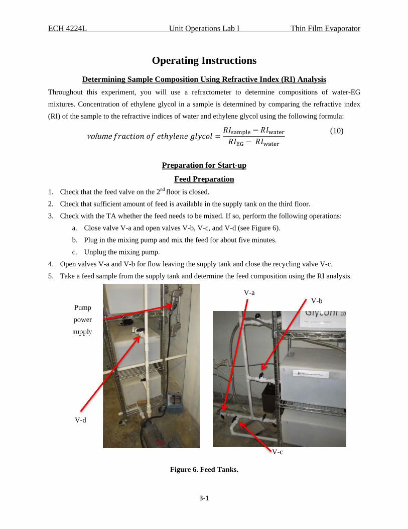
a. Close valve V-a and open valves V-b, V-c, and V-d (see Figure 6).
b. Plug in the mixing pump and mix the feed for about five minutes.
c. Unplug the mixing pump.
4. Open valves V-a and V-b for flow leaving the supply tank and close the recycling valve V-c.
5. Take a feed sample from the supply tank and determine the feed composition using the RI analysis.
Figure 6. Feed Tanks.
Pump
power
supply
V-c
V-d
V-b V-a
ECH 4224L Unit Operations Lab I Thin Film Evaporator
3‐2
Emptying the Product Tanks
NOTE: You need to empty the product tanks both before you start the experiment as well as during the
experiment due to the limited tank capacity.
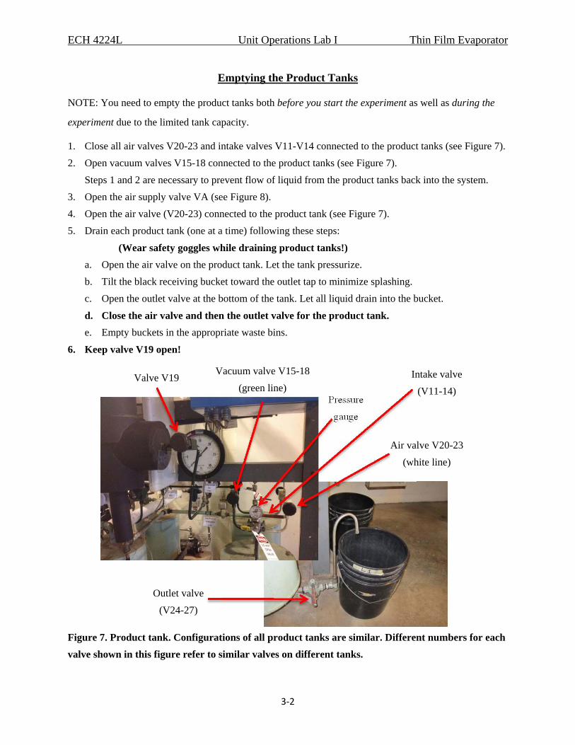
1. Close all air valves V20-23 and intake valves V11-V14 connected to the product tanks (see Figure 7).
2. Open vacuum valves V15-18 connected to the product tanks (see Figure 7).
Steps 1 and 2 are necessary to prevent flow of liquid from the product tanks back into the system.
3. Open the air supply valve VA (see Figure 8).
4. Open the air valve (V20-23) connected to the product tank (see Figure 7).
5. Drain each product tank (one at a time) following these steps:
(Wear safety goggles while draining product tanks!)
a. Open the air valve on the product tank. Let the tank pressurize.
b. Tilt the black receiving bucket toward the outlet tap to minimize splashing.
c. Open the outlet valve at the bottom of the tank. Let all liquid drain into the bucket.
d. Close the air valve and then the outlet valve for the product tank.
e. Empty buckets in the appropriate waste bins.
6. Keep valve V19 open!
Figure 7. Product tank. Configurations of all product tanks are similar. Different numbers for each
valve shown in this figure refer to similar valves on different tanks.
Pressure
gauge
Vacuum valve V15-18
(green line) Intake valve
(V11-14)
Air valve V20-23
(white line)
Outlet valve
(V24-27)
Valve V19
ECH 4224L Unit Operations Lab I Thin Film Evaporator
3‐3
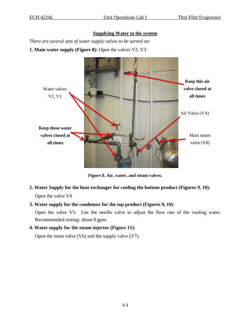
Supplying Water to the system
There are several sets of water supply valves to be turned on:
1. Main water supply (Figure 8): Open the valves V2, V3
Figure 8. Air, water, and steam valves.
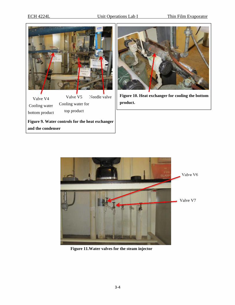
2. Water Supply for the heat exchanger for cooling the bottom product (Figures 9, 10):
Open the valve V4
3. Water supply for the condenser for the top product (Figures 9, 10):
Open the valve V5. Use the needle valve to adjust the flow rate of the cooling water.
Recommended setting: about 8 gpm.
4. Water supply for the steam injector (Figure 11):
Open the main valve (V6) and the supply valve (V7).
Water valves
V2, V3
Air Valve (VA)
Main steam
valve (V8)
Keep this air
valve closed at
all times
Keep these water
valves closed at
all times
ECH 4224L Unit Operations Lab I Thin Film Evaporator
3‐4
Needle valve Valve V4
Cooling water
bottom product
Valve V5
Cooling water for
top product
Figure 9. Water controls for the heat exchanger
and the condenser
Figure 10. Heat exchanger for cooling the bottom
product.
Figure 11.Water valves for the steam injector
Valve V6
Valve V7
ECH 4224L Unit Operations Lab I Thin Film Evaporator
3‐5
Supplying Steam and Evacuating the System
Steam in this system is used for two purposes: (1) heat the evaporator walls and (2) create
vacuum using the steam injector.
1. The first time steam is used, ask the lab assistant for assistance.
2. Open the main steam valve V8 (see Figure 8). Wear gloves! This line will be hot!
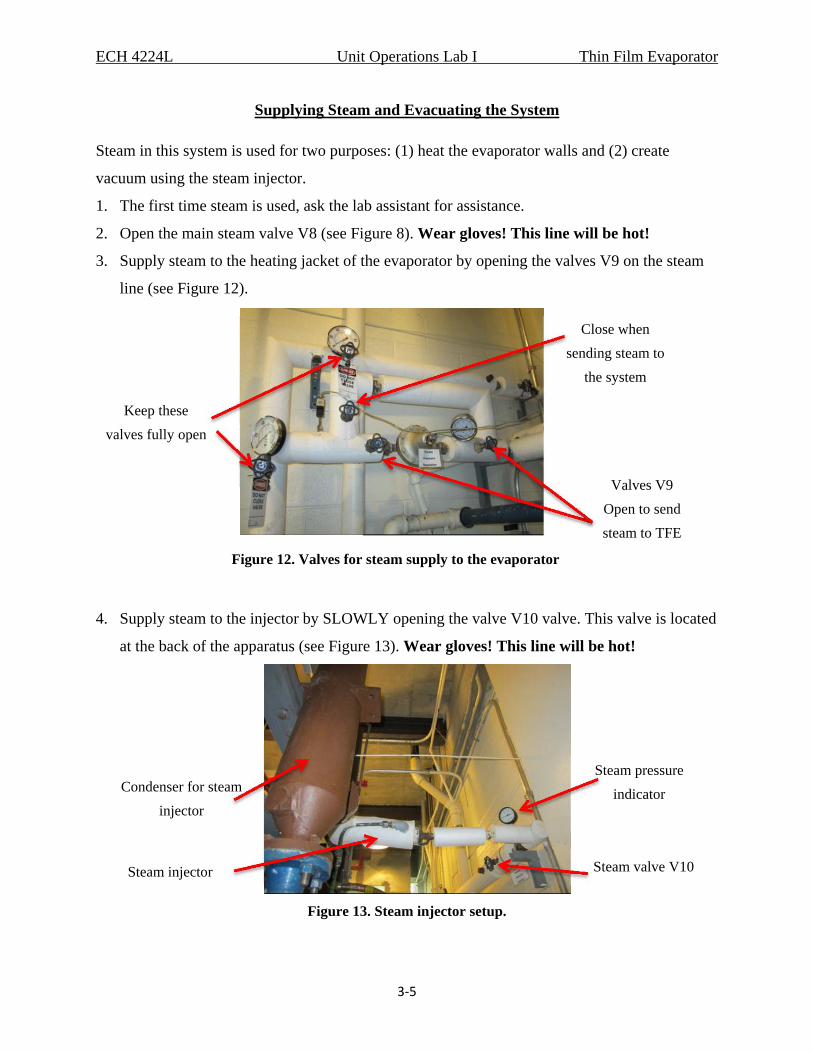
3. Supply steam to the heating jacket of the evaporator by opening the valves V9 on the steam
line (see Figure 12).
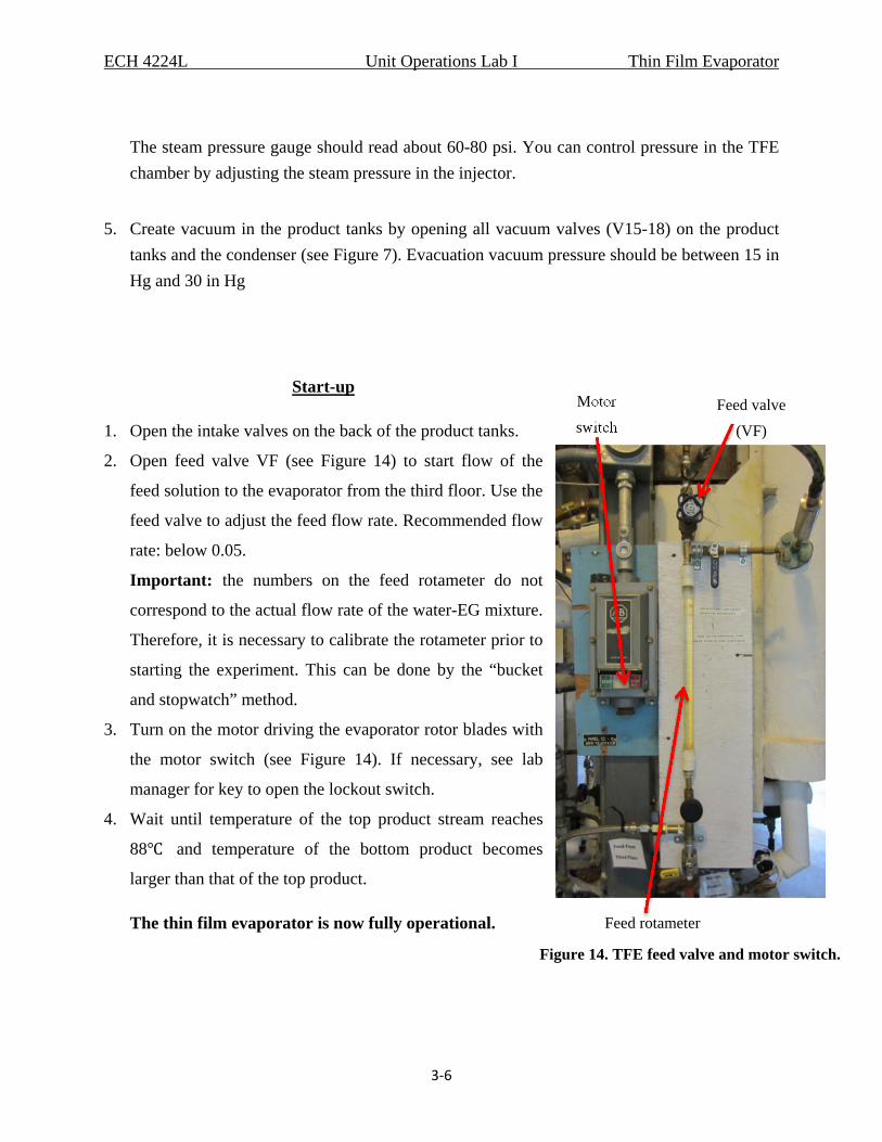
4. Supply steam to the injector by SLOWLY opening the valve V10 valve. This valve is located
at the back of the apparatus (see Figure 13). Wear gloves! This line will be hot!
Figure 13. Steam injector setup.
Steam valve V10
Steam pressure
indicator
Steam injector
Condenser for steam
injector
Keep these
valves fully open
Valves V9
Open to send
steam to TFE
Close when
sending steam to
the system
Figure 12. Valves for steam supply to the evaporator
ECH 4224L Unit Operations Lab I Thin Film Evaporator
3‐6
The steam pressure gauge should read about 60-80 psi. You can control pressure in the TFE
chamber by adjusting the steam pressure in the injector.
5. Create vacuum in the product tanks by opening all vacuum valves (V15-18) on the product
tanks and the condenser (see Figure 7). Evacuation vacuum pressure should be between 15 in
Hg and 30 in Hg
Start-up
1. Open the intake valves on the back of the product tanks.
2. Open feed valve VF (see Figure 14) to start flow of the
feed solution to the evaporator from the third floor. Use the
feed valve to adjust the feed flow rate. Recommended flow
rate: below 0.05.
Important: the numbers on the feed rotameter do not
correspond to the actual flow rate of the water-EG mixture.
Therefore, it is necessary to calibrate the rotameter prior to
starting the experiment. This can be done by the “bucket
and stopwatch” method.
3. Turn on the motor driving the evaporator rotor blades with
the motor switch (see Figure 14). If necessary, see lab
manager for key to open the lockout switch.
4. Wait until temperature of the top product stream reaches
88 and temperature of the bottom product becomes
larger than that of the top product.
The thin film evaporator is now fully operational.
Motor
switch Feed valve
(VF)
Feed rotameter
Figure 14. TFE feed valve and motor switch.
ECH 4224L Unit Operations Lab I Thin Film Evaporator
3‐7
Switching between Product Tanks during the TFE Operation
It is important that you do not perturb the continuous operation of the system when you switch
between the tanks. Otherwise, you may not be able to reach a steady-state.
1. Simultaneously close the intake valves on the full tank and open the intake valves on the
empty tank (see Figure 7).
2. Empty the full tank following the instructions for Emptying the Product Tanks given above.
3. Re-establish the vacuum on the emptied product tanks by opening the vacuum valves V20-23
while the air valves are closed.
4. Make sure the vacuum valves V15-18 are open and the condensed air valve is closed while
the tanks under them are collecting the product.
5. After emptying the tank, obtain the mass of the product. Use this information to estimate the
products flow rate.
6. Determine the product composition using the RI analysis
Shutting Down
1. Turn off the motor for the rotor blades (see Figure 14).
2. Close the feed valve VF (see Figure 14).
3. Close the main steam valve V8 (see Figure 8). Wear gloves! This line will be hot!
4. Close the steam valves V9 to the evaporator (see Figure 12).
Wear gloves! This line will be hot!
5. Close the steam valve V13 to the steam injector (see Figure 8).
Wear gloves! This line will be hot!
6. Close water valves V2-7 (see Figures 8, 9, and 11).
7. Close valves V-a and V-b on the line leaving the bottom of the supply tank (see Figure 6).
8. Empty the product tanks (instructions for emptying the product tanks are given in the Start-
up procedure).
9. Close all valves (air, vacuum, intake, and outlet) on the product tanks.
10. Close the master air valve VA (see Figure 8).
11. Check the tanks for pressurization. If they are pressurized, open the outlet valve to relieve the
pressure.
ECH 4224L Unit Operations Lab I Thin Film Evaporator
3‐8
Data Collection and Analysis
1. Record experimental conditions for each experimental run, including: steam pressure,
pressure in the TFE chamber, feed flow rate, and feed composition.
2. This system takes long time to reach a steady state. In order to ensure that the steady state has
been reached, take samples periodically (15-20 minutes) during each experimental run and
record results of your measurements in the following table:
Here, W is the weight and T is the temperature.
4. Use the information collected in the above table to compute the compositions and flow rates
of the product streams.
5. Due to long time required to reach a steady-state, you will not have enough time to repeat
each experiment 3 times in order to estimate the experimental error. Instead, you can use the
time-averaging, i.e. use the last 3 samples taken from each run to estimate the mean values
and standard deviations of the measured quantities. Of course, you need to verify that the last
3 measurements correspond to a steady-state!
6. To verify reproducibility of your results, run at least one experiment under the same
conditions on two different lab days.
Measurement Time
RItop RIbottom Wtop Wbottom Ttop Tbottom
1 2 3 4 5
…..


