
1
Operation Instruction Manual
High Speed Double Faces Labeling Machine
(Edition1.0)
2
CONTENT 1 Introduction ....................................................................................................... 4
1.1System component ........................................................................................ 4
1.2 System parameter: ....................................................................................... 4
1.3 Human-computer interface: ....................................................................... 4
1.3.1 Human-computer interface ....................................................................................... 4 1.3.2 Operation system start: .............................................................................................. 4 1.3.3 Boot screen: ............................................................................................................... 5 1.3.4 Operation running interface: .................................................................................... 5 1.3.5 Parameter set interface: ............................................................................................ 6
2 Overview ............................................................... Error! Bookmark not defined.
3 Principle and Structure ..................................................................................... 7
3.1 Principle and Structure ............................................................................... 7
3.2 Main components ........................................................................................ 8
3.3 Parameter ..................................................................................................... 8
4 Operation procedure and adjustment ............................................................... 9
4.1 Procedure flow ............................................................................................. 9
4.2 Check the sensor is well. ............................................................................. 9
4.3 Adjustment of the labeling machine ........................................................... 9
4.4 Stripper parallelism adjustment ................................................................ 10
4.5 Adjustment of bottle space and correct device ......................................... 10
4.6 Adjustment of top-pressing device ............................................................ 11

3
4.7 Adjustment of pressing wheel ................................................................... 11
5 Attentions ......................................................................................................... 12
6 Common faults analyses ................................................................................. 12
7 Maintenance .................................................................................................... 13
8 Appendix .......................................................................................................... 13
8.1 Optical fiber sensor specification (See appendix 1) ............................... 13
8.2Sketch map chart (See appendix 2) ........................................................... 13
8.3 Electrical principle chart (See appendix 3) .............................................. 13
9 Packaging lists and After-sale service ............................................................ 14
9.1 packaging list ............................................................................................. 14
9.2 Product certificate ..................................................................................... 14
9.3 Warranty Card ........................................................................................... 15
9.3.1 From date of sale, the warranty as follow: ............................................................. 15 9.3.2 Check the machine model and machine no. .......................................................... 15 9.3.3 Safe-keeping the invoice and warranty card .......................................................... 15
4
1 Introduction
This machine adopts DELTA-DVP14SS11T2 (Delta) as the core control part for good
working: reasonable electrical design and human-computer software design, providing high
performance and easy operation. 1.1System component:
Human-computer interface
Programmable Logic Controller (PLC): DELTA-DVP14SS11T2 (Delta)
Optical fiber sensors: keyence (Japan)
1.2 System parameter:
Environment: Temperature 5℃-50℃ Humidity 20%-90%
Power supply: Input AC 220V±10%(50Hz) Output DC 24V±2V
PLC: Input AC 220V 8 Transistors Output DC no contact 6 Transistors
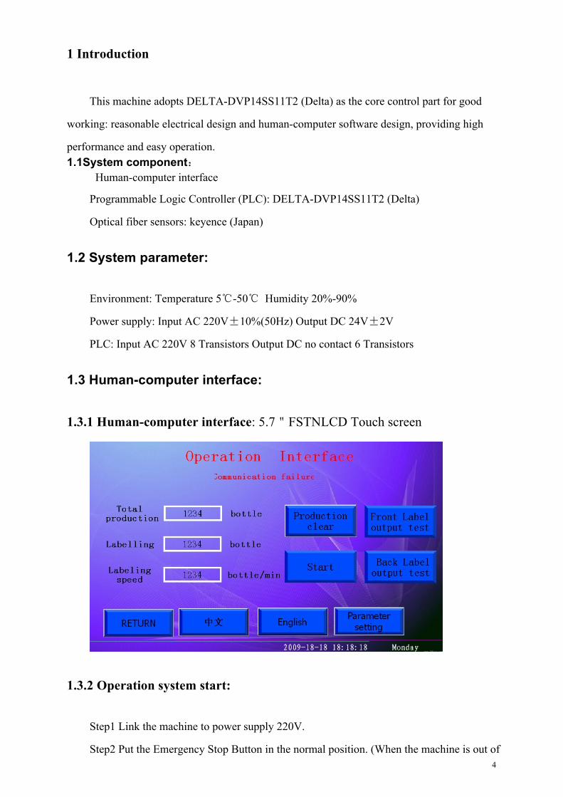
1.3 Human-computer interface:
1.3.1 Human-computer interface: 5.7"FSTNLCD Touch screen
1.3.2 Operation system start:
Step1 Link the machine to power supply 220V.
Step2 Put the Emergency Stop Button in the normal position. (When the machine is out of

5
work, it can cut off the power immediately by pressing this button.)
Step3 The machine will enter into [Boot Screen] 2 s latter.
1.3.3 Boot screen:
1.3.4 Operation running interface:
Entering this interface, you can process as follows:
[ON]: Pressing [ON], machine will start to label; Pressing [OFF], machine stops working.
[Front label test]: Pressing [Front label test], the machine enters testing state. Each pressing,

6
each label feeds. The feeding label quantities do not count.
[Back label test]: The same as [Front label test]. Pressing [Back label test], the machine
enters testing state. Each pressing, each label feeds. The feeding label quantities do not count.
[Clear]: Pressing this button, the total production will be “zero” and start a new count.
[Language set]: Switching the language: English and Chinese.
[Parameter set]: By pressing, enter into parameter set interface.
1.3.5 Parameter set interface:
[Parameter group]: This group can store a number of parameter setting data, convenient for
changes of different size bottles and labels. You can call out the parameter setting data directly
from the database without resetting, which will save a lot of time and improve work efficiency.
[Protection impulse]: This is for the protection of the stepper motor, with setting of 200-1000P.
[Back label frequency]: You can set the labeling speed. The unit is Hz. The setting is decided by
bottle diameter, label length and the labeling speed you want. Usually, the bigger the bottle is and
the longer the label is, the slower the labeling speed is. On the contrary, the labeling speed will be
quick. If not, the machine will can not normal working.
[Front label frequency]: The same as [Back label frequency].
[Front label OFF]: The front labeling head will not work if shut this. The back labeling head
will continue working for single face labeling.
[Back label OFF]: The same as [Front label OFF].
[Coding delay]: This can set the coding signal connection time, with adjustment of coding depth

7
and coding time to suit for different type printers. The unit is second.
[Conveyor OFF]: This can start and stop the conveyor motor to offer time for the operation
people to deal with the bottles on the conveyor. Pressing, the conveyor will stop moving.
[Coding OFF]: When the machine is working, you can choose starting the printer or closing the
printer. If do not need the printer or stop the printer for a moment, pressing this button.
[Inverter frequency]: This is to control the speed of the conveyor.
•2Overview
LM-DT-type double faces labeling machine is made to achieve the goal of the rationalization
of production design. The whole labeling process is automatic, with easy operation, high speed
and nice surface. This labeling machine is mainly applied in food, beverage, pharmaceutical,
cosmetic, chemical industry for flat and square bottle single face or two faces labeling.
3 Principle and Structure
3.1 Principle and Structure
LM-DT High speed double faces labeling machine is composed of two labeling heads,
located in the two sides of the conveyor. When labeling, the processes are as follow:
Step1 Bottles move on the conveyor driving by the conveyor motor.
Step2 Bottles will be spaced and corrected by the spacing and correcting device to keep a certain
distance from each other. Bottles come to the labeling area.
Step3 When detecting the bottles, the optical fiber sensor sends the signal to the PLC. After
dealing, PLC sends the output signal to the stepper motor.
Step4 The stepper feeds the label one by one: label comes out from the stripper and stick on the
bottle. Also, the back paper will be collected. Label will be made smooth after pressing of the
brush.
Step5 Measuring sensor detects the space between labels. Label will move forwards the same
length. Then stepper motor stops moving and label stop feeding.
Step6 Lastly, bottle will pass through the sponge wheel and the label will be pressing more
smoothly. The process over and the next bottle will be labeled.
The machine adopts stepper motor driver, Delta PLC control system, human-computer
interface, Keyence optical fiber sensor and some other imported parts: Microsoft control system

8
and human-computer interface, smart design and powerful functions. Absorbing many
leading-edge technologies, the machine is one of the best labeling machines in the packaging
industry. With auto alarm function when meets broken label, no label etc. Optional is a set ribbon
coding machine. This machine uses T6 aluminum alloy and stainless steel304 and other
high-quality production, working well in line with GMP standard. LM-DT double faces labeling
machine is a very good cost-effective products.
3.2 Main components
Commodity Function Remarks
Cabinet Support the above parts and protect the Electrical components
Conveyor Transporting the bottles Chain conveyor/Belt conveyor/Roller conveyor
Labeling head Unreeling pine Label tray
Feeding-label Driving label moving Steeper motor
Label stripper Strip the label from the back paper
Bottle-space
device
Keeping the bottle certain distance from each other
Bottle-space
Label-pressing
device
Making label smooth on the bottle Brush and sponge wheel
Adjust frame Adjusting all the parts suitable
Electric control Control the whole system
ribbon printing
machine / inkjet
printer
Printing and coding Optional
Smooth device Make the label smooth For double or single face labeler
3.3 Parameter
Power supply: AC110V/220V 50/60Hz
Power: 1500W
Production capacity: 30-150 bottle/min (Speed is adjustable and is decided by bottle

9
diameter and label length)
Batch number: coding machine motor drive or cylinder drive (optional)
Weight: 300KG
Dimension: 2800mm*1500*1530mm
4 Operation procedure and adjustment
4.1 Procedure flow
Step1 Fix the label roll and adjust the height.
Step2 Adjusting the height of the bottle-bar, top-pressing device, bottle space and correct
device
Step3 Turn on the power and photoelectric switch; for printing, it need preheat about 15min.
Step4 Turn on the motors and sensor switch, testing labeling.
Step5 Ensuring no fault, production begins.
Step6 Turn off the machine.
4.2 Check the sensor is well.
See appendix 1 (Optical fiber sensor specification)
4.3 Adjustment of the labeling machine
Loosen the upper and lower fix braces---Change the height of machine by rotating the
handwheel---Interlock the braces.
10
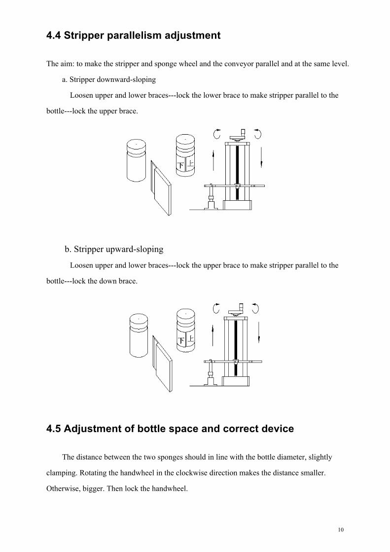
4.4 Stripper parallelism adjustment
The aim: to make the stripper and sponge wheel and the conveyor parallel and at the same level.
a. Stripper downward-sloping
Loosen upper and lower braces---lock the lower brace to make stripper parallel to the
bottle---lock the upper brace.
b. Stripper upward-sloping
Loosen upper and lower braces---lock the upper brace to make stripper parallel to the
bottle---lock the down brace.
4.5 Adjustment of bottle space and correct device
The distance between the two sponges should in line with the bottle diameter, slightly
clamping. Rotating the handwheel in the clockwise direction makes the distance smaller.
Otherwise, bigger. Then lock the handwheel.
11
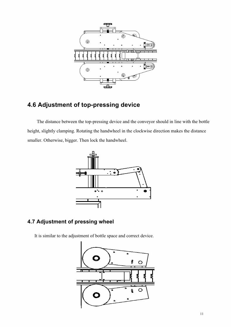
4.6 Adjustment of top-pressing device
The distance between the top-pressing device and the conveyor should in line with the bottle
height, slightly clamping. Rotating the handwheel in the clockwise direction makes the distance
smaller. Otherwise, bigger. Then lock the handwheel.
4.7 Adjustment of pressing wheel
It is similar to the adjustment of bottle space and correct device.

12
5 Attentions
a. The power is AC220V. Ensure to use ground wire. Before start the machine, be sure good
installation.
b. There are two directions of the labeling machine: from left to right and from right to left.
c. Make sure the guide rings below the guide wheel at the same level. The upper guide ring
sits besides the label.
d. Make sure the position of the sensor, otherwise it will wrinkle when labeling.
e. Make sure the correct label passing patch.
6 Common faults analyses
Faults Reasons Solutions
a. Label
broken
Over-pressure of Synchronous
belt drives pulleys Loosen the regulating nut
Stuck of Synchronous belt drives pulley Add a pad on the Synchronous belt
drives pulleys
Label brakes too much Loosen brake
Label over-pressure Loosen the clamping screw
Printer over-pressure Adjust the printer
Wearing of label bottom Change the label or adjust guide rail
Stripper out of position Adjusting
b.Nolabel
feeding
Check the sensor Adjusting the sensor sensitivity
Broken of fiber amplifier Change new one
c. Label
wrinkle
Hard brush Change soft one
Label too quick Let speed slow
Bottle too irregular Change bottles
d.Label
inclined
Label not at the same level Adjust the label disk
Too quicker speed Slower
Labeling head inclined Adjust it
13
7 Maintenance
a. Ensure good connection with the ground wire and install anti-creeping protection switch.
b. For the human-computer interface, no sharp touch and alcohol washing. When dusty,
wipe with cotton.
c. When the PLC is electrified, do not change the switches and connectors to avoid
damaging the electric control parts.
d. If the machine is long time no using, unplug the power plug.
8 Appendix
8.1 Optical fiber sensor specification (See appendix 1)
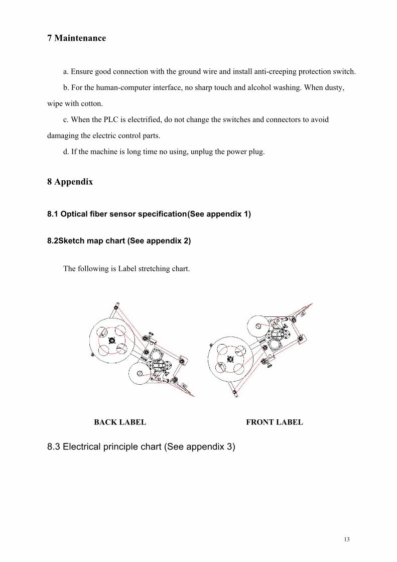
8.2Sketch map chart (See appendix 2)
The following is Label stretching chart.
BACK LABEL FRONT LABEL
8.3 Electrical principle chart (See appendix 3)

14
9 Packaging lists and After-sale service
9.1 packaging list
LM-DT High Speed Double Face Labeling Machine Package Lists
Machine No:
Num Commodity Specification Qty Remarks
1 Labeling machine LM-DT 1 set
2 Synchronous belt Sanxing 2 pieces
3 Screw driver Cross 1Piece
4 Screw driver Straight 1piece
5 Socket head wrench 1 set
6 adjustable spanner 1 piece
All above parts are packing.
Packing test:
Packing date:
9.2 Product certificate
Product certificate Machine is permitted
To leave factory after strict inspection.
Machine commodity
Model
Factory number
Inspector
Date
15
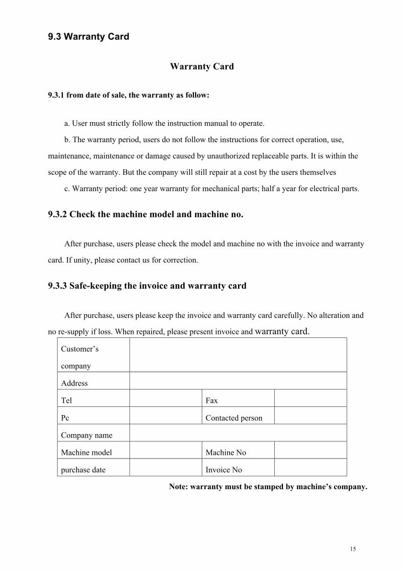
9.3 Warranty Card
Warranty Card
9.3.1 from date of sale, the warranty as follow:
a. User must strictly follow the instruction manual to operate.
b. The warranty period, users do not follow the instructions for correct operation, use,
maintenance, maintenance or damage caused by unauthorized replaceable parts. It is within the
scope of the warranty. But the company will still repair at a cost by the users themselves
c. Warranty period: one year warranty for mechanical parts; half a year for electrical parts.
9.3.2 Check the machine model and machine no.
After purchase, users please check the model and machine no with the invoice and warranty
card. If unity, please contact us for correction.
9.3.3 Safe-keeping the invoice and warranty card
After purchase, users please keep the invoice and warranty card carefully. No alteration and
no re-supply if loss. When repaired, please present invoice and warranty card.
Customer’s
company
Address
Tel Fax
Pc Contacted person
Company name
Machine model Machine No
purchase date Invoice No
Note: warranty must be stamped by machine’s company.


