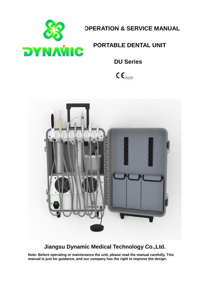
OPERATION & SERVICE MANUAL
PORTABLE DENTAL UNIT
DU Series
0123
Jiangsu Dynamic Medical Technology Co.,Ltd.
Note: Before operating or maintenance the unit, please read the manual carefully. This manual is just for guidance, and our company has the right to improve the design.

1
This manual will guide you to operate the light precisely. Please read all accompanying documents
before the first use!
Disclaimer
This manual doesn't refer to any description of Dynamic products' specifications and accessories.
If you have any questions about these two aspects, please read the according agreement and
packing list, or contact the agents directly.
We have made great efforts to write this manual correctly and completely. But because of the
continuous advance for technology and the amendments for relevant laws, we may make some
changes to products and manuals. We reserve the right to change without any other previous
declaration. We promise to improve our products and service continuously. If you find inconformity
between manual and product, want to know latest information, or have any questions, please visit
our website!
Limited warranty
For the device with warranty document, we will provide after-sale service referring to the warranty
document only.
For the device without warranty document, we will provide after-sale service referring to the
agreement. It means this purchaser don’t have the right to enjoy our after-sale service. So, if you
want to buy such kind product, you should require the seller to promise you after-sale service.
This product could be sold in the countries and regions where it meets laws only.
In the maximum limit of law permitting, in the following conditions, we assume no responsibility:
1. The third party requires you to compensation.
2. Incidental or indirect injury and economic loss.
3. Any injury and economic loss because you add other equipments to this product personally.
4. Any injury and economic loss because you use the product in conditions not referred in
manual, or you don’t operate the product according to manual.
5. Any injury and economic loss because of force majeure factors.
You could call our after sale service number: +86-021-51697955
Note: Maybe this number will be changed due to communication network or some other objective
factors, and we will give no further notice.
Copyright
Jiangsu Dynamic has the copyright of this manual, and holds all the rights.
The copyright of other accessories and documents equipped with our products belongs to the
according organizations or persons.
2
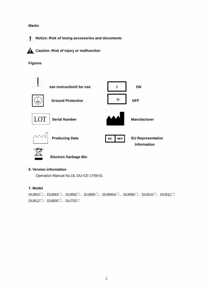
Marks
Notice: Risk of losing accessories and documents
Caution: Risk of injury or malfunction
Figures
see instructionS for use ON
Ground Protective OFF
Serial Number Manufacturer
Producing Date EU Representative
Information
Electron Garbage Bin
6. Version information
Operation Manual No.DL-DU-CE-1709-01
7. Model
DU852□、DU893□、DU892□、DU895□、DU895A□、DU896□、DU810□、DU811□
DU812□、DU800□、DU752□
I
O
LOT

3
Content
1. Brief Introduction 4
2. Technical Parameters 6
3. Product Structure and Installation 11
4. Test and Application 20
5. Operation and Maintenance 22
6. Trouble-shooting 24
7. Fundamental Diagram 25
8. Water and Air Diagrams of DU Portable Dental Units 26
9. Circuit Diagrams of DU Dental Units 30
10. Attentions 32
11. Labels on Outside Packing 32
12. Packing List 33
4
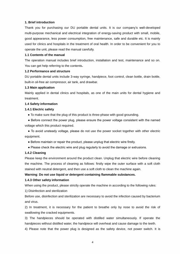
1. Brief introduction
Thank you for purchasing our DU portable dental units. It is our company’s well-developed
multi-purpose mechanical and electrical integration of energy-saving product with small, mobile,
good appearance, less power consumption, free maintenance, safe and durable etc. It is mainly
used for clinics and hospitals in the treatment of oral health. In order to be convenient for you to
operate the unit, please read the manual carefully.
1.1 Contents of the manual
The operation manual includes brief introduction, installation and test, maintenance and so on.
You can get help referring to the contents.
1.2 Performance and structure
DU portable dental units include 3-way syringe, handpiece, foot control, clean bottle, drain bottle,
built-in oil-free air compressor, air tank, and drawbar.
1.3 Main application
Mainly applied in dental clinics and hospitals, as one of the main units for dental hygiene and
treatment.
1.4 Safety information
1.4.1 Electric safety
● To make sure that the plug of this product is three-phase with good grounding.
● Before connect the power plug, please ensure the power voltage consistent with the named
voltage which this product required.
● To avoid unsteady voltage, please do not use the power socket together with other electric
equipment.
● Before maintain or repair the product, please unplug that electric wire firstly.
● Please check the electric wire and plug regularly to avoid the damage or extrusions.
1.4.2 Cleaning
Please keep the environment around the product clean. Unplug that electric wire before cleaning
the machine. The process of cleaning as follows: firstly wipe the outer surface with a soft cloth
stained with neutral detergent, and then use a soft cloth to clean the machine again.
Warning: Do not use liquid or detergent containing flammable substances.
1.4.3 Other safety information
When using the product, please strictly operate the machine in according to the following rules:
1) Disinfection and sterilization
Before use, disinfection and sterilization are necessary to avoid the infection caused by bacterium
and virus.
2) In treatment, it is necessary for the patient to breathe only by nose to avoid the risk of
swallowing the cracked equipments.
3) The handpieces should be operated with distilled water simultaneously. If operate the
handpieces without distilled water, the handpiece will overheat and cause damage to the teeth.
4) Please note that the power plug is designed as the safety device, not power switch. It is

5
necessary to ensure the power plug can be unplugged from the socket without extrusions.
Warning: Correct grounding is necessary to avoid the risk of electric shock.
5) Only skilled staff through training can operate the equipment. Undue operation may cause
severe injury.
6) Equipment cannot be used in flammable mixture environment.
7) Equipment cannot be used in anesthetic and air, oxygen, nitrogen mixture environment.
8) Don't put the equipment together with oxygen cylinder.
9) Please do not operate the equipment or replace the accessories when the following situations
occur:
● Damage of the power plug
● Equipment cannot work normally
● Breakdown of the equipment
● Water inlet of the equipment
● Loud or shrill noise, overheating outlet air or foul smells during operation.
When above situations occur, please contact with the manufacturer or local agent. In order to be
convenient for us to offer after sale service, please offer drawing of electrical circuit, air and water
connection diagram, packing list and other useful information when necessary.
10) Please use original or qualified disinfector.
11) Turn off the power when the operator left.
12) Dispose of waste liquid and waste solid according to the local health regulations.
13) Do not use and store the equipment outside the specified environment.
14) Keep accessories from dropping to avoid damages.
15) Keep the electric wire from loosing in the process of treatment.
16) Please use accessories from original manufacturer.
17) Keep the equipment in a solid and horizontal level.
1.5 Periodic safety inspections
The following projects should be inspected at least once a year by the trained and skilled person:
Check the equipment and the functional status of the machinery in the attachment.
Check whether the mark of the related safety is clean or not
Check whether the blown fuse accords with the current rating fuse and the characteristic
Check whether the performance of the equipment accords with the description in the manual.
Testing whether the ground resistance is less than the required resistance described in the
IEC60601-1: 0.1ohm.
Testing whether the earth leakage current is less than the required resistance described in the
IEC60601-1: normal Condition: 500uA, single fault condition 1000uA.
Testing whether the Shell leakage current is less than the required electric current described in the
IEC60601-1: normal Condition: 100uA, single fault condition: 500 uA.
Testing whether the patient current leakage is less than the required electric current described in
the IEC60601-1: for the alternating current: 0.5Ma, for the continuous current: 10 uA.
6
Testing whether the patient leakage current is less than the required current described in the
IEC60601-1 in the single fault condition: for the alternating current: 0.5Ma, for the continuous
current: 50uA.
Testing whether the auxiliary leakage current is less than required current described in the
IEC60601-1:
The alternating current in the normal condition: 0.1Ma, for the continuous current 10uA;
The alternating current in the single fault condition: 0.5Ma, for the continuous current is 50 uA.
Write down all the test data on the operational diary, if the above test is failed or the equipments
can not work normally, then you should maintain the equipment.
1.6 The requirements of external components
1.6.1 All external parts must be certified by CE, and also you need to check technical parameters
related to spare parts, sketch map, technical manuals and instructions, production qualification
test report and other contents.
1.6.2 Check whether the parts will accord with the requirements of the company before Installation
the parts.
1.6.3 The installation parts should be operated by the trained person.
1.7 All models
DU852, DU893, DU892, DU895, DU895A, DU896, DU810, DU811, DU812, DU800, DU752
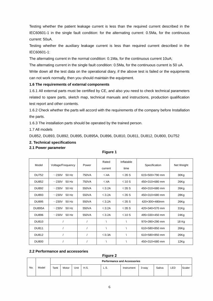
2. Technical specifications
2.1 Power parameter Figure 1
Model Voltage/Frequency Power Rated
current
Inflatable
time Specification Net Weight
DU752 ~230V 50 Hz 750VA ≤4A ≤35 S 615×500×790 mm 30Kg
DU852 ~230V 50 Hz 750VA ≤4A ≤10 S 450×310×680 mm 26Kg
DU892 ~230V 50 Hz 550VA ≤3.2A ≤35 S 450×310×680 mm 26Kg
DU893 ~230V 50 Hz 550VA ≤3.2A ≤35 S 450×310×680 mm 28Kg
DU895 ~230V 50 Hz 550VA ≤3.2A ≤35 S 420×300×480mm 26Kg
DU895A ~230V 50 Hz 550VA ≤3.2A ≤35 S 420×340×570 mm 31Kg
DU896 ~230V 50 Hz 550VA ≤3.2A ≤10 S 495×330×450 mm 24Kg
DU810 / / \ \ 970×390×290 mm 18 Kg
DU811 / / \ \ 610×580×850 mm 26Kg
DU812 / / ≤0.3A \ 610×580×850 mm 26Kg
DU800 / / \ \ 450×310×680 mm 12Kg
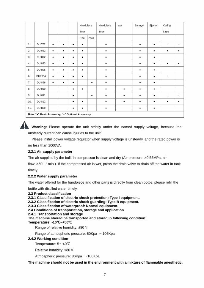
2.2 Performance and accessories
Figure 2
No.
Model
Performance and Accessories
Tank Motor Unit H.S. L.S. Instrument 3-way Saliva LED Scaler
7
Handpiece
Tube
Handpiece
Tube
tray Syringe Ejector Curing
Light
1pc 2pcs
1. DU 752 ● ● ● ● ● ● ● ○ ○
2. DU 852 ● ● ● ● ● ● ● ● ●
3. DU 892 ● ● ● ● ● ● ●
4. DU 893 ● ● ● ● ● ● ● ● ●
5. DU 895 ● ● ● ● ● ● ●
6. DU895A ● ● ● ● ● ● ● ○
7. DU 896 ● ● ● ● ● ● ●
8. DU 810 ● ● ● ● ● ●
9. DU 811 ● ● ● ● ● ● ○ ○
10. DU 812 ● ● ● ● ● ● ● ●
11. DU 800 ● ● ● ● ●
Note: “●” Basic Accessory, “○” Optional Accessory
Warning: Please operate the unit strictly under the named supply voltage, because the
unsteady current can cause injuries to the unit.
Please install power voltage regulator when supply voltage is unsteady, and the rated power is
no less than 1000VA.
2.2.1 Air supply parameter
The air supplied by the built-in compressor is clean and dry (Air pressure: >0.55MPa, air
flow: >50L/min ). If the compressed air is wet, press the drain valve to drain off the water in tank
timely.
2.2.2 Water supply parameter
The water offered for the handpiece and other parts is directly from clean bottle; please refill the
bottle with distilled water timely.
2.3 Product classification 2.3.1 Classification of electric shock protection: Type I equipment. 2.3.2 Classification of electric shock guarding: Type B equipment. 2.3.3 Classification of waterproof: Normal equipment. 2.4 Conditions of transportation, storage and application 2.4.1 Transportation and storage The machine should be transported and stored in following condition: Temperature: -10℃~+50℃
Range of relative humidity: ≤90%
Range of atmospheric pressure: 50Kpa ~106Kpa
2.4.2 Working condition
Temperature: 5~40℃
Relative humidity: ≤80%
Atmospheric pressure: 86Kpa ~106Kpa
The machine should not be used in the environment with a mixture of flammable anesthetic,
8
oxygen and nitrogen.
2.5 Electromagnetic Compatibility
The machine pass the electromagnetic compatibility test of IEC60601-1-2, should you have any
questions, please contact our service department, thank you!
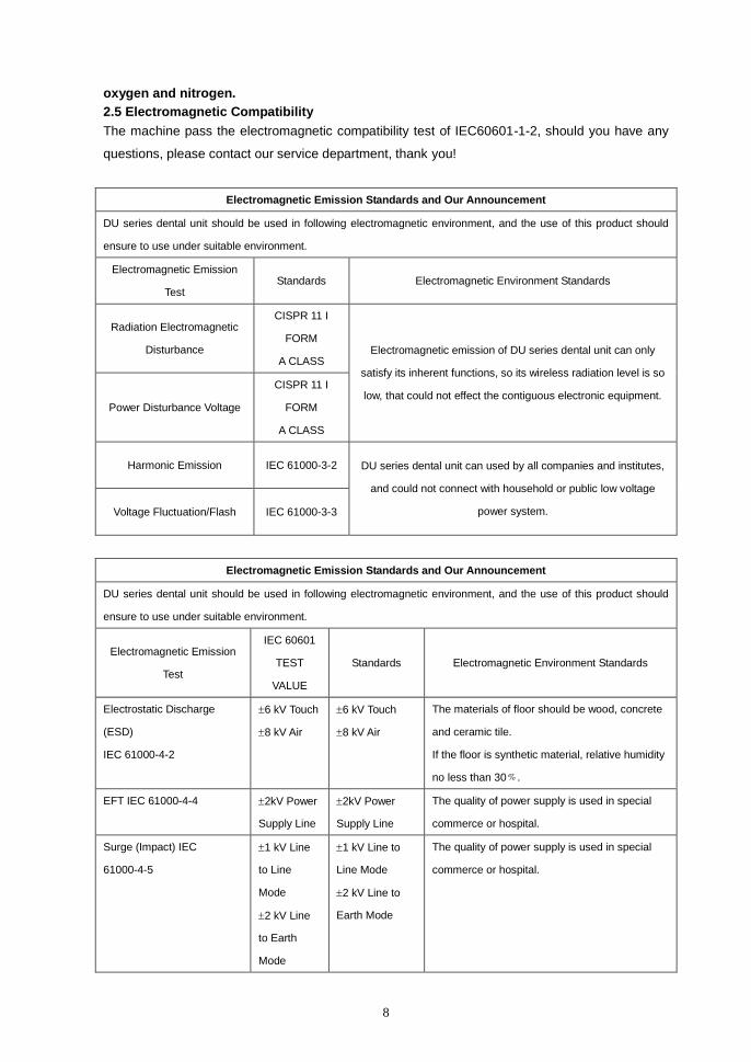
Electromagnetic Emission Standards and Our Announcement
DU series dental unit should be used in following electromagnetic environment, and the use of this product should
ensure to use under suitable environment.
Electromagnetic Emission
Test Standards Electromagnetic Environment Standards
Radiation Electromagnetic
Disturbance
CISPR 11 I
FORM
A CLASS Electromagnetic emission of DU series dental unit can only
satisfy its inherent functions, so its wireless radiation level is so
low, that could not effect the contiguous electronic equipment. Power Disturbance Voltage
CISPR 11 I
FORM
A CLASS
Harmonic Emission IEC 61000-3-2 DU series dental unit can used by all companies and institutes,
and could not connect with household or public low voltage
power system. Voltage Fluctuation/Flash IEC 61000-3-3
Electromagnetic Emission Standards and Our Announcement
DU series dental unit should be used in following electromagnetic environment, and the use of this product should
ensure to use under suitable environment.
Electromagnetic Emission
Test
IEC 60601
TEST
VALUE
Standards Electromagnetic Environment Standards
Electrostatic Discharge
(ESD)
IEC 61000-4-2
6 kV Touch
8 kV Air
6 kV Touch
8 kV Air
The materials of floor should be wood, concrete
and ceramic tile.
If the floor is synthetic material, relative humidity
no less than 30﹪.
EFT IEC 61000-4-4 2kV Power
Supply Line
2kV Power
Supply Line
The quality of power supply is used in special
commerce or hospital.
Surge (Impact) IEC
61000-4-5
1 kV Line
to Line
Mode
2 kV Line
to Earth
Mode
1 kV Line to
Line Mode
2 kV Line to
Earth Mode
The quality of power supply is used in special
commerce or hospital.

9
Voltage Sag And Short
Supply Interruption Voltage
Change
IEC 61000-4-11
<5% UT
(>95% dip in
UT)
for 0.5 cycle
40% UT
(60% dip in
UT)
for 5 cycles
70% UT
(30% dip in
UT)
for 25 cycles
<5% UT
(>95% dip in
UT) for 5 sec
<5% UT
(>95% dip in
UT)
for 0.5 cycle
40% UT
(60% dip in UT)
for 5 cycles
70% UT
(30% dip in UT)
for 25 cycles
<5% UT
(>95% dip in
UT)
for 5 sec
The quality of power supply is used in special
commerce or hospital. When DU series portable
dental units need to continuous operation when
grid interrupts, please use uninterruptable power
output.
Power Frequency Magnetic
Fields IEC 61000-4-8
3A/m 3A/m /
Note: UT is alternating voltage before testing.
Electromagnetic Emission Standards and Our Announcement
DU series dental unit should be used in following electromagnetic environment, and the use of this product should
ensure to use under suitable environment.
Protection Test
IEC 60601
TEST
VALUE
Standards Electromagnetic Environment Standards
Radio
transmission
IEC 61000-4-6
Radio radiation
IEC 61000-4-3
3 Vrms
150 kHz to
80 MHz
3 V/m
80 MHz to
2.5 GHz
3 Vrms
3 V/m
Portable or mobile radio communication equipment should
stay away from DU series portable dental unit, including
cables, also should leave more than the recommended
separation distance calculated.
Recommended separation distance
PV
d
1
5.3
PE
d
1
5.3 80 MHz 800 MHz
PE
d
1
7 800 MHz 2.5 GHz
P: is the fixed output power by radio equipment
manufacturer, the unit is W.
D: Recommend separation distance. Fixed radio transmitter,
determined by electromagnetic measurements, A: Each
frequency band must be less than the standard
10
requirements. B: The equipment maybe interfered nearby
the device with following symbols:
Note: 1 Between 80 MHz and 800 MHz, higher frequency range applies.
2 This specification maybe do not suitable for all situations, because the propagation of electromagnetic
waves can be effected by the absorption and reflection of buildings, objects and people.
A: The electromagnetic strength of fixed radio transmitter, such as radar station, cordless telephone and mobile
radios, amateur radio, FM and AM radio and television, this can not be predicted in theory. The estimated of
electromagnetic environment depends on the fixed radio transmitters, and electromagnetic measurement points
should be considered. If the magnetic strength nearby the DU series is more than the above allowed value, then
DU series portable dental unit should be observed to verify by the normal operation. In addition, when to
re-install the DU series portable dental unit, the above information should you measured again.
B: Frequencies above 150kHz to 80 MHz, the electromagnetic intensity should be less than 3V/m.
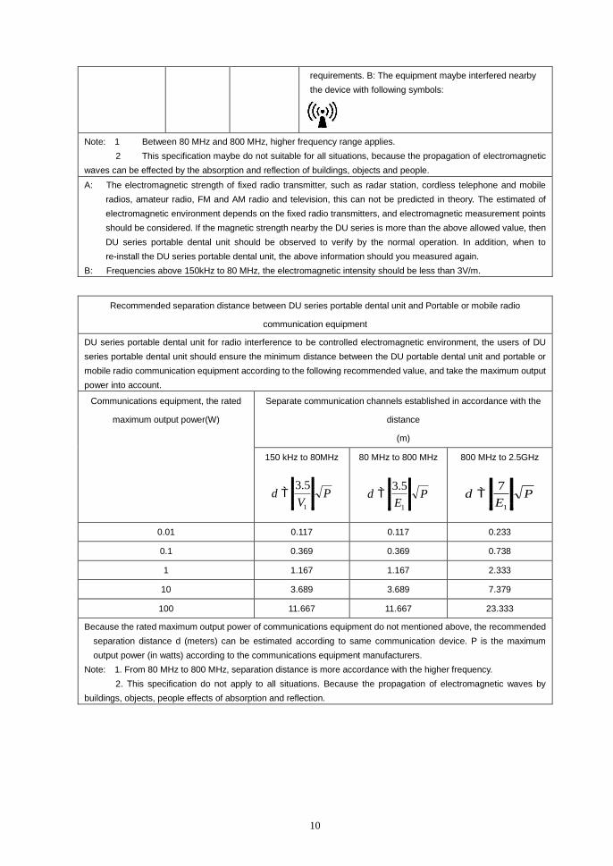
Recommended separation distance between DU series portable dental unit and Portable or mobile radio
communication equipment
DU series portable dental unit for radio interference to be controlled electromagnetic environment, the users of DU
series portable dental unit should ensure the minimum distance between the DU portable dental unit and portable or
mobile radio communication equipment according to the following recommended value, and take the maximum output
power into account.
Communications equipment, the rated
maximum output power(W)
Separate communication channels established in accordance with the
distance
(m)
150 kHz to 80MHz
PV
d
1
5.3
80 MHz to 800 MHz
PE
d
1
5.3
800 MHz to 2.5GHz
PE
d
1
7
0.01 0.117 0.117 0.233
0.1 0.369 0.369 0.738
1 1.167 1.167 2.333
10 3.689 3.689 7.379
100 11.667 11.667 23.333
Because the rated maximum output power of communications equipment do not mentioned above, the recommended
separation distance d (meters) can be estimated according to same communication device. P is the maximum
output power (in watts) according to the communications equipment manufacturers.
Note: 1. From 80 MHz to 800 MHz, separation distance is more accordance with the higher frequency.
2. This specification do not apply to all situations. Because the propagation of electromagnetic waves by
buildings, objects, people effects of absorption and reflection.
11
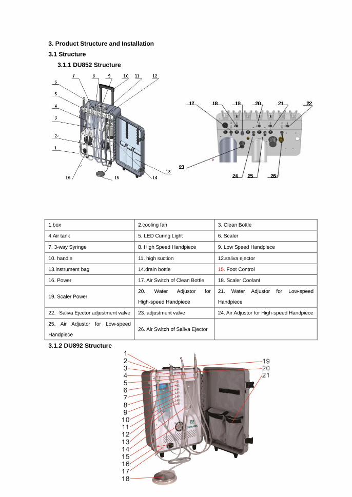
3. Product Structure and Installation
3.1 Structure
3.1.1 DU852 Structure
1.box 2.cooling fan 3. Clean Bottle
4.Air tank 5. LED Curing Light 6. Scaler
7. 3-way Syringe 8. High Speed Handpiece 9. Low Speed Handpiece
10. handle 11. high suction 12.saliva ejector
13.instrument bag 14.drain bottle 15. Foot Control
16. Power 17. Air Switch of Clean Bottle 18. Scaler Coolant
19. Scaler Power 20. Water Adjustor for
High-speed Handpiece
21. Water Adjustor for Low-speed
Handpiece
22. Saliva Ejector adjustment valve 23. adjustment valve 24. Air Adjustor for High-speed Handpiece
25. Air Adjustor for Low-speed
Handpiece 26. Air Switch of Saliva Ejector
3.1.2 DU892 Structure
12
1. Saliva Ejector 8.High-speed/Low-speed Transferring Switch 15. Fan
2. Box 9. Air Adjustor for High-speed Handpiece 16. Power
3. 3-way Syringe 10. Air Adjustor for Low-speed Handpiece 17. Drain Valve
4. High Speed Handpiece 11. Water Adjustor for High-speed Handpiece 18. Foot Control
5. Low Speed Handpiece 12. Water Adjustor for Low-speed Handpiece 19. Instrument Bag
6. Air Switch of Saliva Ejector 13. Dirt Bottle 20. Pressure Gauge of
Handpiece
7. Air Switch of Clean Bottle 14. Clean Bottle 21. Rod
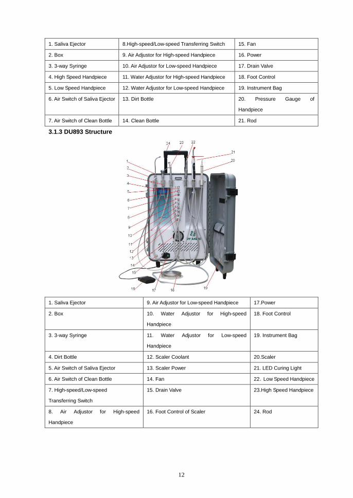
3.1.3 DU893 Structure
1. Saliva Ejector 9. Air Adjustor for Low-speed Handpiece 17.Power
2. Box 10. Water Adjustor for High-speed
Handpiece
18. Foot Control
3. 3-way Syringe 11. Water Adjustor for Low-speed
Handpiece
19. Instrument Bag
4. Dirt Bottle 12. Scaler Coolant 20.Scaler
5. Air Switch of Saliva Ejector 13. Scaler Power 21. LED Curing Light
6. Air Switch of Clean Bottle 14. Fan 22.Low Speed Handpiece
7. High-speed/Low-speed
Transferring Switch
15. Drain Valve 23.High Speed Handpiece
8. Air Adjustor for High-speed
Handpiece
16. Foot Control of Scaler 24. Rod

13
3.1.4 DU895 Structure
1. Handle 7. Power 13.High-speed/Low-speed
Transferring Switch.
2. Pressure Switch 8. Clean Bottle 14. Water Adjustor for Handpieces
3. Tank Pressure Gauge 9. Foot Control 15. Air Adjustor for Handpieces
4. Quick Connector of Air Outlet 10. 3-way Syringe 16. Air Switch of Clean Bottle
5. Air Regulator & Filter 11.High Speed Handpiece
6. Tank 12. Low Speed Handpiece
3.1.5 DU895A Structure

14
1. High Speed Handpiece 6. Foot Control 11.Air Adjustor for Low-speed
Handpiece
2. 3-way Syringe 7. Water Adjustor for High-speed
Handpiece
12. Air Adjustor for High-speed
Handpiece
3. Rod 8. Water Adjustor for Low-speed
Handpiece
13. Low Speed Handpiece
4. Pressure Gauge of Handpiece 9. Air Switch of Clean Bottle
5. Power 10.High-speed/Low-speed
Transferring Switch
3.1.6 DU896 Structure

15
3.1.7 DU810 Structure
1. 3-way Syringe 7. Water Adjustor for Low-speed
Handpiece
13. Air Adjustor of Saliva Ejector
2.Stainless Steel Instrument Tray 8. Dirt Bottle 14. Air Switch of Saliva Ejector
3. Air Adjustor for High-speed
Handpiece
9. Bracket 15. Air Switch of Clean Bottle
4. Water Adjustor for High-speed
Handpiece
10. Foot Control 16. Low Speed Handpiece
5. Air Adjustor for Low-speed
Handpiece
11. Clean Bottle 17. High Speed Handpiece
6. Saliva Ejector 12.High-speed/Low-speed
Transferring Switch
18. Pressure Gauge of Handpiece
1. Box 10. Low Speed Handpiece 19. Air Intake
2. Pressure Gauge of Regulator Valve 11. Air Switch of Saliva Ejector 20. Solenoid Valve
3. Regulator Valve 12. Air Switch of Clean Bottle 21. Pressure Switch
4. Saliva Ejector 13. Water Adjustor for High-speed Handpiece II 22. Check Valve
5. 3-way Syringe 14. Water Adjustor for Low-speed Handpiece 23. Safety Valve
6. High Speed Handpiece I 15. Air Adjustor for Handpiece 24. Motor
7. High Speed Handpiece II 16. Pressure gauge of Handpiece 25. Clean Bottle
8. Clapboard 17. Water Adjustor for High-speed Handpiece I
9. Foot Control 18. Dirt Bottle
16
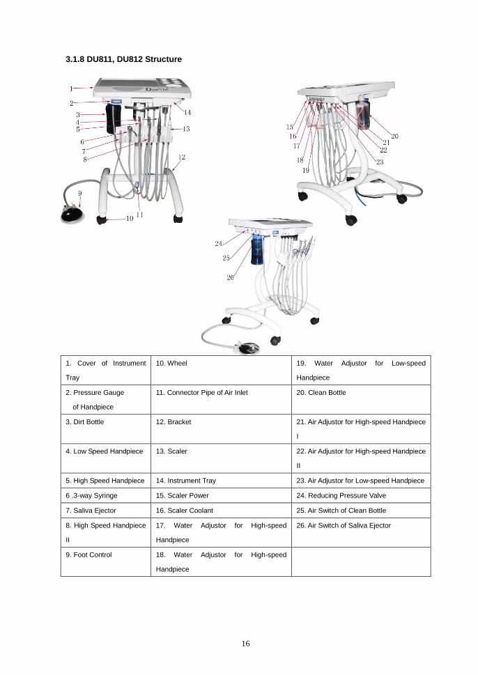
3.1.8 DU811, DU812 Structure
1. Cover of Instrument
Tray
10. Wheel 19. Water Adjustor for Low-speed
Handpiece
2. Pressure Gauge
of Handpiece
11. Connector Pipe of Air Inlet 20. Clean Bottle
3. Dirt Bottle 12. Bracket 21. Air Adjustor for High-speed Handpiece
I
4. Low Speed Handpiece 13. Scaler 22. Air Adjustor for High-speed Handpiece
II
5. High Speed Handpiece 14. Instrument Tray 23. Air Adjustor for Low-speed Handpiece
6 .3-way Syringe 15. Scaler Power 24. Reducing Pressure Valve
7. Saliva Ejector 16. Scaler Coolant 25. Air Switch of Clean Bottle
8. High Speed Handpiece
II
17. Water Adjustor for High-speed
Handpiece
26. Air Switch of Saliva Ejector
9. Foot Control 18. Water Adjustor for High-speed
Handpiece
17
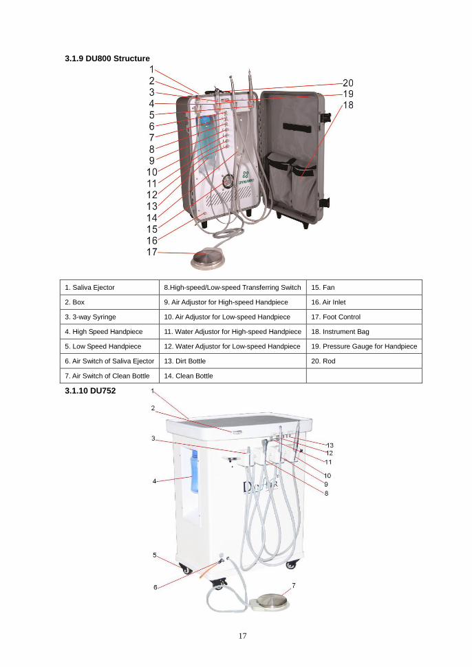
3.1.9 DU800 Structure
1. Saliva Ejector 8.High-speed/Low-speed Transferring Switch 15. Fan
2. Box 9. Air Adjustor for High-speed Handpiece 16. Air Inlet
3. 3-way Syringe 10. Air Adjustor for Low-speed Handpiece 17. Foot Control
4. High Speed Handpiece 11. Water Adjustor for High-speed Handpiece 18. Instrument Bag
5. Low Speed Handpiece 12. Water Adjustor for Low-speed Handpiece 19. Pressure Gauge for Handpiece
6. Air Switch of Saliva Ejector 13. Dirt Bottle 20. Rod
7. Air Switch of Clean Bottle 14. Clean Bottle
3.1.10 DU752
18
1. Top Cover 6. Drain Valve 11. Water Adjustor for High-speed Handpiece
2. Pressure Gauge 7. Foot Control 12. Water Adjustor for Low-speed Handpiece
3. Saliva Ejector 8. 3-way Syringe 13. Triple Diaphragm Valve
4. Dirt Bottle 9. High Speed Handpiece
5. Wheel 10. Low Speed Handpiece
3.2 Installation
3.2.1 Open the box and check
Open the box, and to check the unit is good or not. And to check the accessory are complete or
not, according to the packing list. If any questions, please contact our distributor or our company
directly.
3.2.2 Installation
To place the dental unit on ground, that is flat and solid. To open the box, and take out the foot
control and water bottle on the ground, then take out the high speed handpiece, low speed
handpiece and water bottle, hang them on the rack separately.
3.2.3 Handpeice
Our handpiece is 4 holes handpeice, M4 handpiece connector. Please connect the handpiece and
handpiece connector better according to the manual, and please note that do not run the
handpiece without the pressure.
3.2.4 Scaler (DU893, DU812, DU852)
The installation of scaler, please refer to the manual, and turn the head of scaler tighten, or there
will be no power outlet.
Warning: There must be water of scaler, of will harm the patient and affect the life of
scaler.
3.2.5 LED curing light (DU893, DU812, DU852)
The installation of LED curing light, please refer the manual carefully.
3.2.6 Power
Take out the power line from the box, connect the power line with the box, and then connect the
other side with the plug.
Note: Please do not share the plug with other machines, in order to avoid the unstable
of voltage, and result of damaging the products.

19
4. Test
4.1 Air supply
Before using, please turn on the power, the built-in air compressor will work automatically, and
compress the air to the tank. The pressure of the tank will be increased from 0 Bar to 8Bar, when
the pressure is on the 8bar, the air compressor will stop working. When the pressure of the tank is
below 5Bar, the air compressor will begin to work, and on the 8Bar, will stop working. This
happens repeated.
Note: In order to avoid accident, the unprofessional person does not allow operating or
fixing the unit.
4.2 Handpiece
The unit has one high speed handpiece and low speed handpice. The water of handpiece is
coming from the water bottle directly. The water pressure is determined by the air pressure in the
water bottle, and controlled by the special pressure valve in the box. The way of adding water: To
turn off the “Air switch”, after the exhausting of air in the bottle completely, and to pick up the water
bottle clockwise, to add the distiller water into the bottle, and turn the bottle tightly
counterclockwise. Then turn on the “Air switch”, the process of adding water completely.
Pick off the handpiece from rack, and please turn the “Low speed /high speed transferring switch”
to the “high speed handpiece”, press the foot control, turn the “Pressure Adjustor of High Speed
Handpiece” counterclockwise, to adjust the handpiece to spray water from small to large. The
turbine of handpiece start to spring water: namely that the handpiece begin to work.
Pick off the handpiece from rack, and please turn the “Low speed /high speed transferring switch”
to the “low speed handpiece”, press the foot control, turn the “Pressure Adjustor of Low Speed
Handpiece” counterclockwise, to adjust the handpiece to spray water from small to large. The
turbine of handpiece start to spring water: namely that the handpiece begin to work.
Note: This time, the “Pressure gauge of handpiece” in the panel is the working pressure
of handpiece, when using the handpiece, please do not exceed the max pressure of
handpiece, and avoiding the harm of handpiece. To adjust the handpiece carefully, the turbine
of handpiece is the precision devices, please read the manual before using carefully.
4.3 3-way syringe
The unit is equipped with a 3-way syringe, which use the distilled water together with handpieces.
The inlet water tube and inlet air tube are connected to connector of the back panel. Press down
the ring nut and insert the nozzle, and then lock the nozzle by resetting the ring nut. Check
whether the air and gas from 3-way syringe is consistent with mark on the unit.
4.4 Saliva ejector
The unit is equipped with a saliva ejector. Open the switch, use adjustor to adjust the suction flow,
it could work normally.

20
Note:
1. The unit could only use alone, it could not use together with handpieces at the same time. If not,
it would affect normal use of handpieces.
2. Suck a cup of purified water, eliminate the seeper in the tube and clean the saliva bottle each
day after use.
3. When cleaning, screw it off in an anticlockwise direction then use the disinfectant to clean it.
Then screw it on the counterclockwise. (Note to tighten)
4: When the sewage collection bottle exceeds the highest water mark in the logo, please
clean the sewage in time, and then loaded on to continue using.
4.5 Ultrasonic Scaler (DU893, DU896, DU812, DU852)
The unit is equipped with an ultrasonic scaler. Pick up the ultrasonic scaler from the shelf; tread
down the foot control, then it could be used normally. The power output could be adjusted. The
adjustor is equipped on the face panel.
The head of the ultrasonic scaler must be screwed tighten. If not, there would have no efficient
power output. The parts are rigid, please read the operation manual carefully.
Note: The ultrasonic scaler only could work with water supply, or that would damage the
ultrasonic scale.
4.6 LED curing light (DU893, DU896, DU812, DU852)
The unit is equipped with LED curing light. From the accessories, you may find the operation
manual of curing light.
4.7 Air regulator and filter
To be sure the air by inputting the unit is stable, clean and dry; we equip an air regulator and filter
on the air inlet of the unit. The air pressure would be stable, while it would not exceed the setting
value. At the same time, the air regulator and filter could filter the air impurities (Filtration accuracy
would be equal or greater than 25μm.) and the water. The water by filtering will gather in filtering
cup, after a period of time, it must be more water gathered. Then you must drain off the water, so
as not to affect the filtering effect.
In general, any of the following conditions having, you need to drain off the water by the air
regulator and filter.
1) By using more than one weeks
2) The water in the filtering cup occupies three quarters of the volume
3) The color of the water in the filtering cup is changed. (Not colorless transparent water)
The detail methods of draining off the water for air regulator and filter are following:
Open the front panel of the unit, then clockwise rotate the nut at the filter bottom, then the water
would be drained off. When finishing drain off the water, counterclockwise rotate the nut, it would
be ok. To protect the environment, you could pad bibulous object on the air outlet, such as cotton,
clean paper, sponge, etc. Then it could absorb the water.
4.8 Clean water bottle

21
For this unit, all water for handpieces, 3-way syringe and Ultrasonic Scaler are from the clean
water bottle. Thus, the user needs to add the distilled water to the clean water bottle timely. The
methods of adding water is following: Turn off the air switch, when the air in the bottle is drained off,
holding the bottle by your hand, rotate clockwise and take down the bottle. After injecting the water,
counterclockwise rotate the bottle and make it tight (note to seal). Then turn on the air switch, the
process of adding water is finished.
In general, any of the following conditions having, you need to clean the bottle and change water
in it.
1) The unit is not used by more than three days.
2) After using every day, you need to clean it.
3) The color of the water in the bottle is changed. (Not colorless transparent water)
5. Operation and Maintenance
5.1. After using saliva bottle, suck a cup of purified water, to clean the tube, suction generator and
other spare parts to protect them from congestion and damage.
5.2. Before using handpieces, the user need to roll and spray by 1 to 2 second to get rid of the dirt
in tube, then prevent the occurrence of cross-infection.
5.3. Wipe surface of the units, prevent harmful materials from corroding the units.
Do not use the cleaner with acid and alkali in corrosive.
5.4. By using handpieces, you need to strictly comply with the operation and maintenance of the
handpieces.
Note: the cleaning and lubrication of handpieces.
5.5. Please turn off the water switch, power switch and air switch when leave after treatment.
5.6. Before first treatment everyday, please make the handpieces and scaler work about 2 minutes,
to clean the water and air tubes.
5.7. After using handpieces and before sterilization, the user needs to make the cleaning and
lubrication, to make the handpieces work normally and prolong the use time. By using handpieces,
you need to strictly comply with the operation and maintenance.
5.8. Sterilization and disinfection of the spray tip of 3-way syringe and handpieces
The following requirements are completely according to the provisions of the handpieces
instruction manual.
● Remove the spray tip of 3-way syringe and handpieces
● Get rid of all visible dirt.
● Make sterilizing in the saturated steam of 132℃by 10 minutes
● After treatment by each patient, please make them sterilizing before treatment for next patient.
Note: For the parts which couldn’t tear down, please use disposable plastic package to
sphere when using.
5.9. Disinfection of ultrasonic scaler

22
The following requirements are completely according to the provisions of the ultrasonic scaler
instruction manual.
● Before sterilization, please clean the ultrasonic scaler and the tip.
● Sterilization condition: 135℃ in 10 minutes or 120℃ in 20 minutes
● Use the soft cloth with 45% cleaner to clean the ultrasonic scaler. Do not make it into any liquid
or directly spray any liquid. Or the liquid would enter into ultrasonic scaler to make it cutting-out
and damage.
5.10. The handpieces tube and connections of ultrasonic scaler could only be cleaned by cleaner
instead of temperature sterilizing.
5.11. Change the fuse tube
5.11.1 Pull out the plug from the socket; pull out the fuse cover from the fuse socket.
5.11.2 Take out the damaged fuse tube
5.11.3 Insert the new fuse tube by make the fuse rating consistent with fusing feature in instruction
manual.
5.11.4 Press the fuse cover in the fuse socket.
Note: The fuse tube unqualified could cause fires!
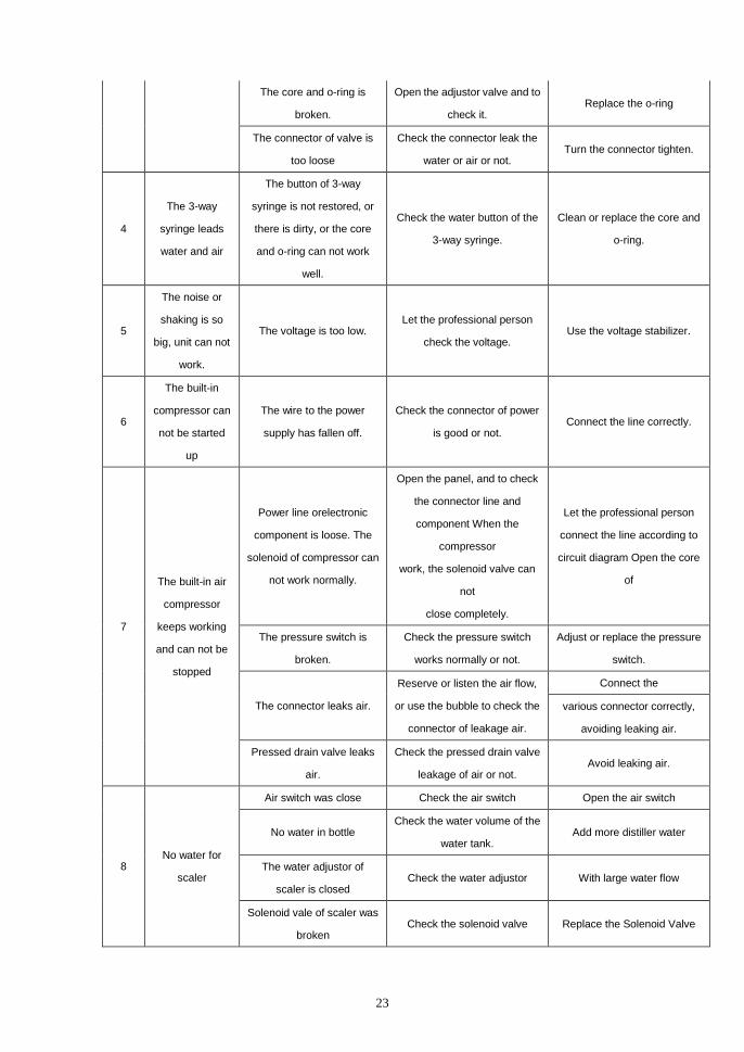
6 Troubleshooting
Item Problem Reason Check Tips
1
The handpiece
can not spray
water while
rotating.
The water in water tank has
been used up.
Check the water volume of the
water tank. Add the distiller water.
Air & water distributing
valve is blocked.
Check the “Air switch” is open
or not, or is working or not.
Open the “Air switch”, or
replace it.
The double air switch can
not work
Check the 3-way syringe
sprays water or not. Regulate the Air & water
distributing valve or clean the
valve core and o-ring.
Check the air pipe is good or
not, or check the core can
work or not.
2
The handpiece
leaks water
when not in
operation.
Air & water distributing
valve fails to function.
Remove one side of the
valves in handpiece, take out
faucet, spring and valve core. replace the valve core and
o-ring Check there is any dirty, and
o-ring can work or not.
The foot switch is not
restored.
The pressure gauge does not
decrease when foot switch is
put up, to check the o-ring of
foot control.
Open the cover of foot control,
and clean the o-ring.
3 The air switch
leak water or air The core is circled too far.
Open the adjustor valve and to
check it. Install the core correctly.
23
The core and o-ring is
broken.
Open the adjustor valve and to
check it. Replace the o-ring
The connector of valve is
too loose
Check the connector leak the
water or air or not. Turn the connector tighten.
4
The 3-way
syringe leads
water and air
The button of 3-way
syringe is not restored, or
there is dirty, or the core
and o-ring can not work
well.
Check the water button of the
3-way syringe.
Clean or replace the core and
o-ring.
5
The noise or
shaking is so
big, unit can not
work.
The voltage is too low. Let the professional person
check the voltage. Use the voltage stabilizer.
6
The built-in
compressor can
not be started
up
The wire to the power
supply has fallen off.
Check the connector of power
is good or not. Connect the line correctly.
7
The built-in air
compressor
keeps working
and can not be
stopped
Power line orelectronic
component is loose. The
solenoid of compressor can
not work normally.
Open the panel, and to check
the connector line and
component When the
compressor
work, the solenoid valve can
not
close completely.
Let the professional person
connect the line according to
circuit diagram Open the core
of
The pressure switch is
broken.
Check the pressure switch
works normally or not.
Adjust or replace the pressure
switch.
The connector leaks air.
Reserve or listen the air flow,
or use the bubble to check the
connector of leakage air.
Connect the
various connector correctly,
avoiding leaking air.
Pressed drain valve leaks
air.
Check the pressed drain valve
leakage of air or not. Avoid leaking air.
8 No water for
scaler
Air switch was close Check the air switch Open the air switch
No water in bottle Check the water volume of the
water tank. Add more distiller water
The water adjustor of
scaler is closed Check the water adjustor With large water flow
Solenoid vale of scaler was
broken Check the solenoid valve Replace the Solenoid Valve
24
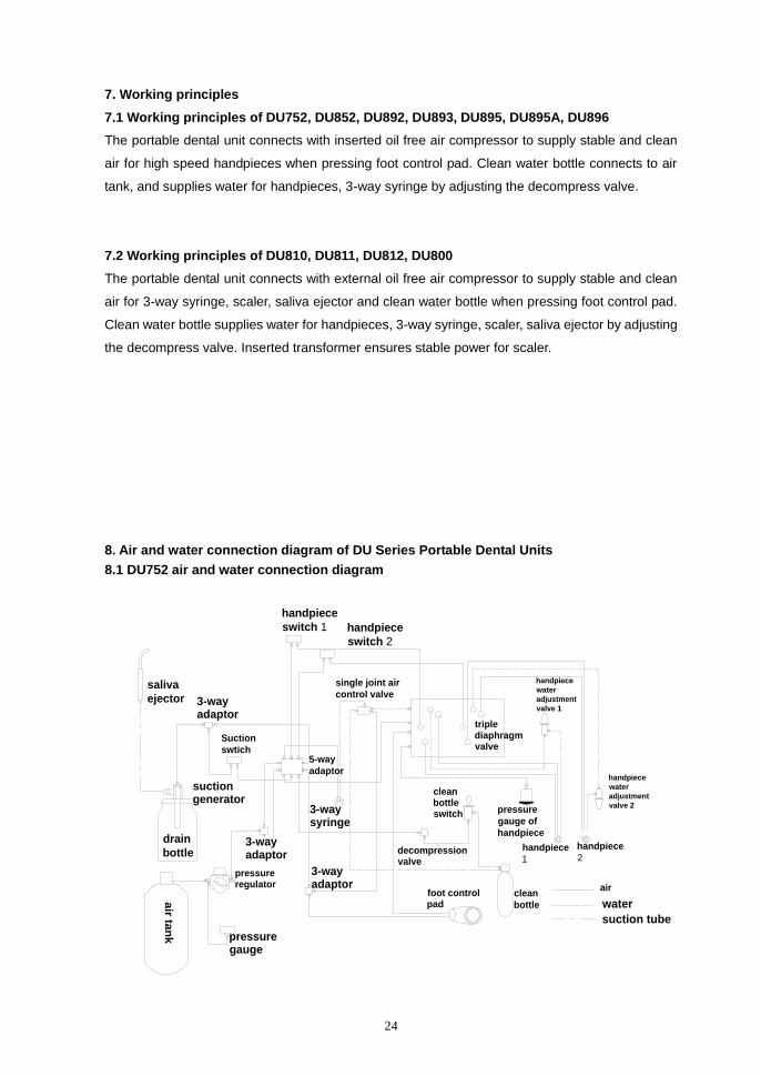
7. Working principles
7.1 Working principles of DU752, DU852, DU892, DU893, DU895, DU895A, DU896
The portable dental unit connects with inserted oil free air compressor to supply stable and clean
air for high speed handpieces when pressing foot control pad. Clean water bottle connects to air
tank, and supplies water for handpieces, 3-way syringe by adjusting the decompress valve.
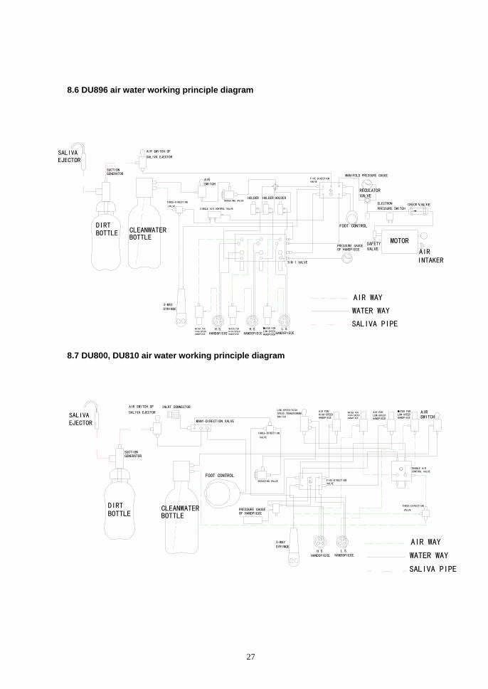
7.2 Working principles of DU810, DU811, DU812, DU800
The portable dental unit connects with external oil free air compressor to supply stable and clean
air for 3-way syringe, scaler, saliva ejector and clean water bottle when pressing foot control pad.
Clean water bottle supplies water for handpieces, 3-way syringe, scaler, saliva ejector by adjusting
the decompress valve. Inserted transformer ensures stable power for scaler.
8. Air and water connection diagram of DU Series Portable Dental Units
8.1 DU752 air and water connection diagram
3-way adaptor
handpiece
water
adjustment
valve 2
handpiece
switch 2
3-way adaptor
single joint air
control valve
triple diaphragm valve
handpiece
switch 1
decompression valve
Suction
swtich
pressure gauge
suction generator
handpiece
water
adjustment
valve 1
clean bottle switch pressure
gauge of
handpiece
saliva
ejector
drain
bottle
air ta
nk
clean
bottle
foot control pad
air
suction tube
water
handpiece
1
handpiece
2
3-way syringe
5-way
adaptor
pressure regulator
3-way adaptor
25
ELECTRON PRESSURE SWITCH
SCALER
COOLANT
SCALER
SOLENOID
STRONG SUCTION GENERATOR
PRESSURE
REGULATING VALVE
STRONG SUCTION SWITCH
REGULATINGVALVE FOR STRONG SUCTION
LOW SPEED/HIGH SPEED TRANSFERRNG SWITCH
AIR FOR HIGH-SPEED HANDPIECE
WATER FOR HIGH-SPEED HANDPIECE
AIR FOR LOW-SPEED HANDPIECE
WATER FOR LOW-SPEEDHANDPIECE
DOUBLE AIR CONTROL VALVE
FIVE-DIRECTION VALVE
REDUCING VALVE
STRONG SUCTION TIP
DRAINAGE BOTTLE FORWAAK SUCTION
DRAINAGE BOTTLE FOR STRONG SUCTION
CHECK VALVE
TANK
MOTOR
CLEANWATER BOTTLE
FOOT CONTROL
SALIVA EJECTOR
AIR SWITCH OF
SALIVA EJECTOR
AJUSTOR VALVE OF SALIVA EJECTOR
SUCTION GENERATOR
PRESSURE GAUGEOF HANDPIECE
AIR WAY
SALIVA PIPE
WATER WAY
SCALER H.S.HANDSPIECE
L.S.HANDSPIECE
3-WAY SYRINGE
AIR SWITCH
WATER FOR
LOW-SPEED
HANDPIECE
WATER FOR
HIGH-SPEED
HANDPIECE
FIVE-DIRECTION VALVE
AIR FOR LOW-SPEED
HANDPIECE
AIR FOR HIGH-SPEED HANDPIECE LOW SPEED/HIGH SPEED TRANSFERRNG SWITCH DOUBLE AIR
CONTROL VALVE
五通
THREE-
DIRECTIONVALVE
EXHAUST SOLENOID VALVESAFETY VALVE MOTOR
AIR INTAKER PRESSURE SWITCH
TANK
SALIVA EJECTOR
AIR SWITCH OF SALIVA EJECTOR
REGULATOR VALVE
SUCTION GENERATOR
DIRT BOTTLE
DRAIN PIPE
AIRFILTER REGULATOR
THREE CONNECTOR
EXHAUST PORTPRESS DRAIN VALVE
AIR WAY
WATER WAYSALIVA PIPE
CLEANWATER BOTTLEFOOT CONTROL
H.S.HANDSPIECE
L.S.HANDSPIECE
3-WAY SYRINGE
PRESSURE GAUGE OF HANDPIECE
AIR SWITCH
3-IN-VALVE
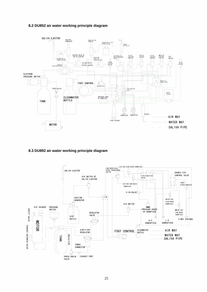
8.2 DU852 air water working principle diagram
8.3 DU892 air water working principle diagram

26
WATER FOR
LOW-SPEED
HANDPIECE
WATER FOR
HIGH-SPEED
HANDPIECE
DOUBLE AIR
CONTROL VALVEFIVE-DIRECTION VALVE
LOW SPEED/HIGH SPEED TRANSFERRNG SWITCH
AIR FOR LOW-SPEED
HANDPIECE
AIR FOR HIGH-SPEED HANDPIECE
SCALER
REGULATOR VALVE
MOTOR
FIVE-DIRECTIONVALVE
3-WAY SYRINGE H.S.HANDSPIECE
AIRFILTER REGULATOR
WATER WAYSALIVA PIPE
AIR WAYFOOT CONTROL
CLEANWATER BOTTLE
AIR SWITCH OF SALIVA EJECTOR
AJUSTOR VALVE OF SALIVA EJECTOR
PRESSURE SWITCH
AIR INTAKER
EXHAUST SOLENOID VALVE
PRESS DRAIN VALVE
TANK
DIRT BOTTLE
SALIVA EJECTOR
3-IN-VALVE
PRESSURE GAUGE OF HANDPIECE
AIR SWITCHSOLENOID VALVE OF SCAER
WATER REGULATOR VALVE OF SCALER
SUCTION GENERATOR
EXHAUST PORT
SAFETY VALVE
DRAIN PIPE
THREE CONNECTOR
L.S.HANDSPIECE
REDUCING VALVE FIVE-DIRECTION VALVE
DOUBLE AIR CONTROL VALVE
WATER FOR LOW-SPEEDHANDPIECE
WATER FOR HIGH-SPEED HANDPIECE
AIR FOR LOW-SPEED HANDPIECE
AIR FOR HIGH-SPEED HANDPIECE LOW SPEED/HIGH
SPEED TRANSFERRNG SWITCH
THREE-DIRECTION
VALVE
MANY-DIRECTION VALVE
CHECK
VALVE
INT AKE
SWITCH
FILTER PRESSURE
REGULATING VALVE
CLEANWATER BOTTLE
FOOT CONTROL
TANK
SAFETY VALVE
MOTOR
EXHAUST SOLENOID VALVE
PRESSURE GAUGE OF HANDPIECE
H.S.HANDSPIECE
L.S.HANDSPIECE
3-WAYSYRINGE
AIR WAY
WATER WAY
AIR SWITCH
8.4 DU893 air water working principle diagram
8.5 DU895、DU895A air water working principle diagram
27
WATER FOR LOW-SPEEDHANDPIECE
WATER FOR HIGH-SPEED HANDPIECE
WATER FOR HIGH-SPEED HANDPIECE
THREE-DIRECTION
VALVE
FIVE-DIRECTION VALVE
CHECK VALVEELECTRON
PRESSURE SWITCH
HOLDERHOLDERHOLDERREDUCING VALVE
MANIFOLD PRESSURE GAUGE
SINGLE AIR CONTROL VALVE
3IN 1 VALVE
AIR WAY
WATER WAY
SALIVA PIPE H.S.HANDSPIECE
L.S.HANDSPIECE
H.S.HANDSPIECE
3-WAY SYRINGE
CLEANWATER BOTTLE
SALIVA EJECTOR
SUCTION GENERATOR
AIR SWITCH OF
SALIVA EJECTOR
DIRT BOTTLE
PRESSURE GAUGEOF HANDPIECE
MOTORSAFETY VALVE AIR
INTAKER
FOOT CONTROL
AIR SWITCH
REGULATOR VALVE
THREE-DIRECTION
VALVE
FIVE-DIRECTION VALVE
DOUBLE AIR CONTROL VALVE
AIR SWITCH
WATER FOR LOW-SPEEDHANDPIECE
AIR FOR LOW-SPEED HANDPIECE
WATER FOR HIGH-SPEED HANDPIECE
AIR FOR HIGH-SPEED HANDPIECE
LOW SPEED/HIGH SPEED TRANSFERRNG SWITCH
THREE-DIRECTION
VALVE
REDUCING VALVE
INLRT CONNECTOR
3-WAY SYRINGE
MANY-DIRECTION VALVE
DIRT BOTTLE
CLEANWATER BOTTLE
SALIVA EJECTOR
SUCTION GENERATOR
AIR SWITCH OF
SALIVA EJECTOR
FOOT CONTROL
PRESSURE GAUGEOF HANDPIECE
AIR WAY
WATER WAY
SALIVA PIPE
H.S.HANDSPIECE
L.S.HANDSPIECE
8.6 DU896 air water working principle diagram
8.7 DU800, DU810 air water working principle diagram

28
CAPACTTOR
MOTOR
SOLENOIDTHE POWER CORD
POWER SWITCH
Fuse 5A
Fuse 5A
POWER SWITCH
ELECTRON
PRESSURE SWITCH
8.8 DU811, DU812 air water working principle diagram
9. DU series portable dental unit electric principle
diagram
9.1 DU752, DU895, DU895A, DU896 electric principle diagram

29
SCALERLED CURING LIGHT
FAN
RED
AC24V
AC220V 110V OV
TRANSFORMER
BLACK
RED
RED
WHITE
WHITE
WHITE
SOLENIDVALVE OF SCALER
SCALERADJUSTOR
MICROSWITCH
PC BOARD OF SCALER
ELECTRIC FOOTCONTROL
ELECTRON PRESSURE SWITCH
POWER SWITCH
SOLENOID
AVIATION PLUG
AVIATION PLUG
AVIATION PLUG
MOTORCAPACTTOR
AVIATION PLUG
THE POWER CORD
Fuse 5A
Fuse 5A
30W
10W
2424
24
24
30W 10W
ELECTRON PRESSURE SWITCH
AVIATION PLUG
AVIATION PLUG
THE POWER CORD
POWER SWITCH
CAPACTTOR
SOLENOID
MOTORFuse 5A
Fuse 5A
9.2 DU892 Electric Principle Diagram
9.3 DU893 electric principle diagram
30
AVIATION PLUG
POWER SWITCH
RED
BLACK WHITE
WHITE
WHITE
MICROSWITCH
AC24V AC24V
AC220V 110V OV
PRESSURE SWITCH
FAN
ELECTRIC FOOTCONTROL
TRANSFORMER
SCALERADJUSTOR
SOLENIDVALVE OF SCALER
PC BOARD OF SCALER
LED CURING LIGHT SCALER
WHITE
BLACK
24
24
24
24
10W
30W
MOTOR
AVIATION PLUG
CAPACTTOR
SOLENOID
RED
Fuse 5A
Fuse 5A
THE POWER CORD
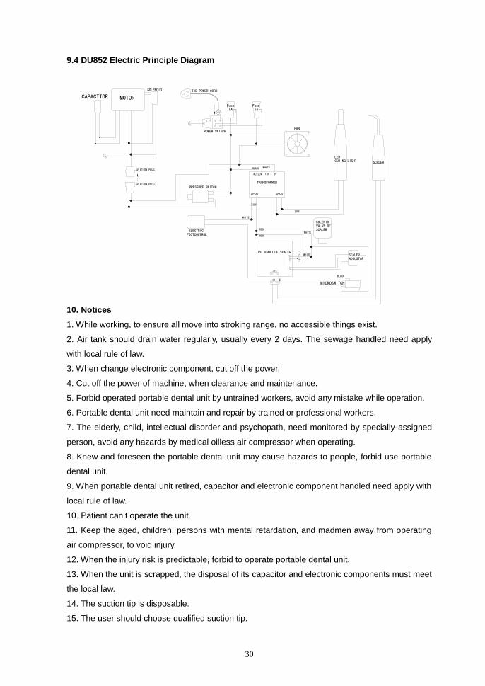
9.4 DU852 Electric Principle Diagram
10. Notices
1. While working, to ensure all move into stroking range, no accessible things exist.
2. Air tank should drain water regularly, usually every 2 days. The sewage handled need apply
with local rule of law.
3. When change electronic component, cut off the power.
4. Cut off the power of machine, when clearance and maintenance.
5. Forbid operated portable dental unit by untrained workers, avoid any mistake while operation.
6. Portable dental unit need maintain and repair by trained or professional workers.
7. The elderly, child, intellectual disorder and psychopath, need monitored by specially-assigned
person, avoid any hazards by medical oilless air compressor when operating.
8. Knew and foreseen the portable dental unit may cause hazards to people, forbid use portable
dental unit.
9. When portable dental unit retired, capacitor and electronic component handled need apply with
local rule of law.
10. Patient can’t operate the unit.
11. Keep the aged, children, persons with mental retardation, and madmen away from operating
air compressor, to void injury.
12. When the injury risk is predictable, forbid to operate portable dental unit.
13. When the unit is scrapped, the disposal of its capacitor and electronic components must meet
the local law.
14. The suction tip is disposable.
15. The user should choose qualified suction tip.
31
16. When the unit is scrapped, the handpiece and drain tubes should be sterilized before
recycling.
17. After 2 months long operation, all connecting bolts on the unit must be reviewed. Tighten the
loosed bolts. Later on, review every 6 months.
18. The user should choose qualified high-speed handpiece, low-speed handpiece and their
accessories such as spray nozzle, head. The products with medical device registration;
19. The pressure gauges (inlet pressure, water bottle pressure, and handpiece pressure) should
be reviewed every 6 months.
20. This unit isn’t equipped with water sterilization system. In order to ensure the unit’s sterilization
won’t affect the quality of water, the handpieces, syringe spray tip, scaler handle and tip should be
sterilized after each use.
21. The treatment of disinfected water released from drainage bottle should be in accordance with
local laws and regulations.
11. External mark and content
1. Following are concluded in external packing:
Product name: Portable dental unit
2. Model: DU ×××××
3. Standard NO.:
4. Product registration NO.:
5. Factory name: Jiangsu Dynamic Medical Technology Co.,Ltd
Factory address: No.108 Xingpu Road, Lujia Town, Kunshan City, Jiangsu Province, 215311。
PEOPLE’S REPUBLIC OF CHINA
6. Packing dimension:
External size: L×W×H
G.W: kg
N.W: kg
7. Nameplate

32
Eiffestrasse 80, 20537 Hamburg, Germany Shanghai lnternational Holding Corp Gmbh (Europe)
Tel:+49-40-2513175 Fax:+49-40-255726
No.108 Xingpu Road, Lujia Town, Kunshan City, Jiangsu Province, 215331.
PEOPLE'S REPUBLIC OF CHINA.
Jiangsu Dynamic Medical Technology Co.,Ltd
0123
VA
see instructionS for use
DU
AC
Portable Dental Unit
Class Ⅰ
Input: 230V 50Hz
Type B
REPEC
SN :
Http://www.dynamicgroup.cn
Intermittent Running
8. Graphics mark:
Upward Fragile Keep dry
Avoid roll Avoid superposition
33
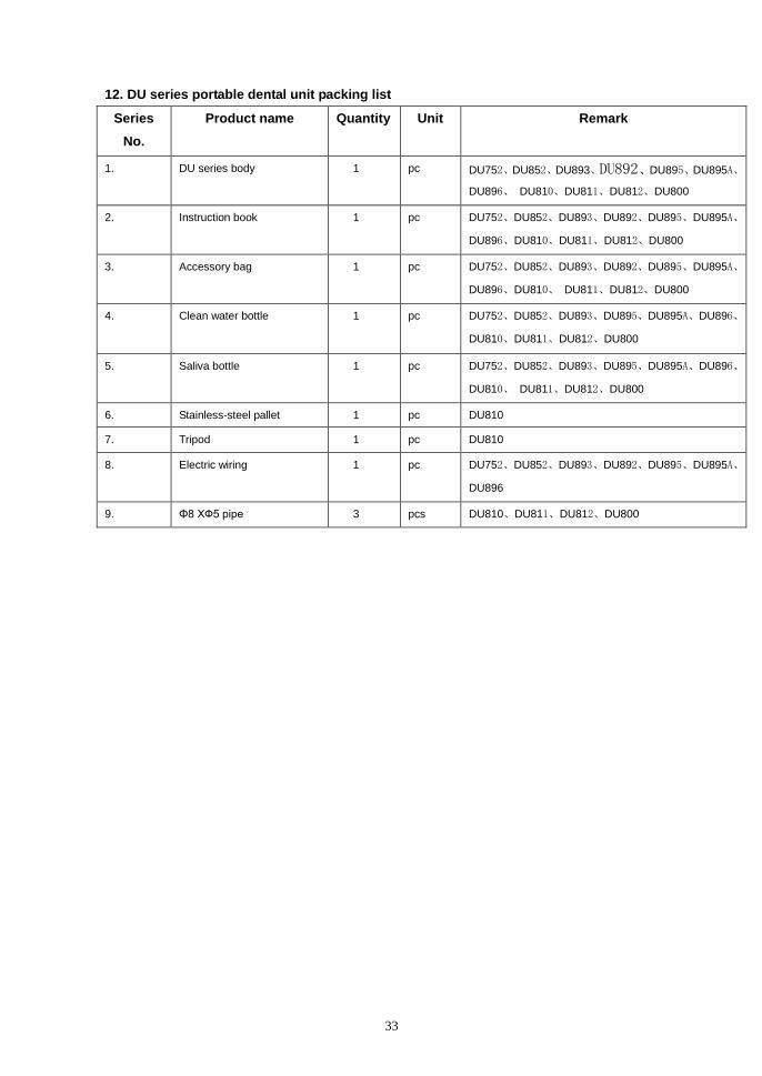
12. DU series portable dental unit packing list
Series
No.
Product name Quantity Unit Remark
1. DU series body 1 pc DU752、DU852、DU893、DU892、DU895、DU895A、
DU896、 DU810、DU811、DU812、DU800
2. Instruction book 1 pc DU752、DU852、DU893、DU892、DU895、DU895A、
DU896、DU810、DU811、DU812、DU800
3. Accessory bag 1 pc DU752、DU852、DU893、DU892、DU895、DU895A、
DU896、DU810、 DU811、DU812、DU800
4. Clean water bottle 1 pc DU752、DU852、DU893、DU895、DU895A、DU896、
DU810、DU811、DU812、DU800
5. Saliva bottle 1 pc DU752、DU852、DU893、DU895、DU895A、DU896、
DU810、 DU811、DU812、DU800
6. Stainless-steel pallet 1 pc DU810
7. Tripod 1 pc DU810
8. Electric wiring 1 pc DU752、DU852、DU893、DU892、DU895、DU895A、
DU896
9. Φ8 XФ5 pipe 3 pcs DU810、DU811、DU812、DU800

34
Shanghai International Holding Corp. Gmbh (Europe)
Address of EU rep: Eiffestrasse 80, 20537 Hamburg, Germany
Tel: +49-40-2513175 Fax: +49-40-255726
Jiangsu Dynamic Medical Technology Co.,Ltd
Factory address: No.108 Xingpu Road, Lujia Town, Kunshan City, Jiangsu
Province, 215331. PEOPLE’S REPUBLIC OF CHINA.
Tel: +86-512-82627666 Fax: +86-512-82603908
Email: [email protected]
Http: //www.dynamicgroup.cn


