OPTIMIZATION OF CYCLONE EFFICIENCY FOR SEPARATION OF
FIBRE AND SHELL FROM PALM KERNEL
KHAIRUL AZLAN BIN ISMAIL
UNIVERSITI MALAYSIA PAHANG

UNIVERSITI MALAYSIA PAHANG
BORANG PENGESAHAN STATUS TESIS JUDUL: OPTIMIZATION OF CYCLONE EFFICIENCY FOR SEPARATION OF FIBRE
AND SHELL FROM PALM KERNEL
SESI PENGAJIAN: 2009/ 2010
Saya KHAIRUL AZLAN BIN ISMAIL
(HURUF BESAR)
mengaku membenarkan kertas projek ini disimpan di Perpustakaan Universiti Malaysia Pahang
dengan syarat-syarat kegunaan seperti berikut :
1. Hakmilik kertas projek adalah di bawah nama penulis melainkan penulisan sebagai projek
bersama dan dibiayai oleh UMP, hakmiliknya adalah kepunyaan UMP.
2. Naskah salinan di dalam bentuk kertas atau mikro hanya boleh dibuat dengan kebenaran bertulis
daripada penulis.
3. Perpustakaan Universiti Malaysia Pahang dibenarkan membuat salinan untuk tujuan pengajian
mereka.
4. Kertas projek hanya boleh diterbitkan dengan kebenaran penulis. Bayaran royalti adalah mengikut
kadar yang dipersetujui kelak.
5. *Saya membenarkan/tidak membenarkan Perpustakaan membuat salinan kertas projek ini
sebagai bahan pertukaran di antara institusi pengajian tinggi.
6. ** Sila tandakan (� )
SULIT (Mengandungi maklumat yang berdarjah keselamatan atau
kepentingan Malaysia seperti yang termaktub di dalam AKTA
RAHSIA RASMI 1972)
TERHAD (Mengandungi maklumat TERHAD yang telah ditentukan oleh
organisasi/badan di mana penyelidikan dijalankan).
� TIDAK TERHAD
Disahkan oleh
(TANDATANGAN PENULIS) (TANDATANGAN PENYELIA)
Alamat Tetap: No. 542, Blok 22, Felda Tn. Hj. Mohd Noor Bin Nawi
Jelai 2, 73480 Gemas, Nama Penyelia
Negeri Sembilan
Tarikh: Tarikh:
CATATAN: * Potong yang tidak berkenaan.
** Jika Kertas Projek ini SULIT atau TERHAD, sila lampirkan surat daripada pihak
berkuasa/organisasi berkenaan dengan menyatakan sekali tempoh tesis ini perlu dikelaskan
sebagai SULIT atau TERHAD.
♦ Tesis ini dimaksudkan sebagai tesis bagi Ijazah Doktor Falsafah dan Sarjana secara
penyelidikan, atau disertasi bagi pengajian secara kerja kursus dan penyelidikan, atau
Laporan Projek Sarjana Muda (PSM)

“Saya/Kami* akui bahawa saya/ kami* telah membaca karya ini dan pada pandangan
saya/kami* karya ini adalah memadai dari segi skop dan kualiti untuk tujuan
penganugerahan ijazah Sarjana Muda/Sarjana/Doktor Falsafah
Kejuruteraan Kimia”.
Tandatangan : ................................................................
Nama Penyelia : Tn. Hj. Mohd Noor Bin Nawi
Tarikh : .................................................................
* Potong yang tidak berkenaan
“I/We* hereby declare that I/we* have read this dissertation and in my/our* opinion
this dissertation is sufficient in terms of scope and quality for the award of the degree
of Bachelor/ Master/Doctor of Philosophy/Doctor of Engineering Chemical
Engineering”.
Signature : ....................................................
Name of Supervisor : Tn. Hj. Mohd Noor Bin Nawi
Date : ....................................................
* Delete as necessary

i
OPTIMIZATION OF CYCLONE EFFICIENCY FOR SEPARATION OF
FIBRE AND SHELL FROM PALM KERNEL
KHAIRUL AZLAN BIN ISMAIL
A dissertation submitted in partial fulfillment of the
Requirements for the award of the degree of
Bachelor of Engineering (Chemical Engineering)
Faculty of Chemical and Natural Resources Engineering
Universiti Malaysia Pahang
APRIL 2010
ii
I declare that this dissertation entitled “Optimization of Cyclone Efficiency for
Separation of Fibre and Shell from Palm Kernel” is the result of my own research
except as cited in the references. The thesis has not been accepted for any degree and is
not concurrently submitted in candidature of any other degree.
Signature : ......................................
Name : Khairul Azlan bin Ismail
Date : .......................................

iii
To my family members,
my friends – reality or virtual,
my fellow colleagues,
and all faculty members
viii
ACKNOWLEDGEMENT
I would like to forward my sincere appreciation to my research project
supervisor, Tn Hj Mohd Noor bin Nawi for his countless guidance and support. For
my academic advisor, Miss Fathie binti Mohd Zakil, your concern and faith in me
during my studies is deeply appreciated.
Special thanks to my beloved campus, Universiti Malaysia Pahang, especially
to Faculty of Chemical and Natural Resource Engineering, for facilities provided
during the execution of this research project. To all supporting staffs of the faculty
and laboratory assistants, thank you. For Dominion Square Sdn. Bhd. company
manager, Mr Wan Zurizal bin Wan Daud, and all his staff, special thanks for your
collaboration in my research.
My appreciation also goes to all my fellow colleagues and friends, who have
been here through all these years. Thanks for all point of views shared, and helping
hand offered in this research project. Our moments and experiences will always be
something sentimental to be remembered.
Last but not least, to my family members. Thank you.

ix
ABSTRACT
In separation of shell and fibre from kernel seed, palm oil mill normally
employed cyclone system. A cyclone collection consists of cylindrical shell, conical
base, dust hopper, and an inlet where the dust laden enters tangentially. Under the
influence of the centrifugal force generated by the spinning gas, the solid particles
are thrown to the wall of the cyclone as the gas spirals upward at the inside of the
cone. The particles slide down to the wall of the cone and into the hopper. The
operating or separating efficiency of a cyclone depends on the magnitude of the
centrifugal force exerted on the particles. The greater the centrifugal force, the
greater the separating efficiency. The magnitude of the centrifugal force depends on
particle mass, gas velocity within the cyclone and cyclone diameter. For a practical
test to increase the cyclone efficiency for kernel recovery, gas velocity can be
manipulated to achieve highest separation efficiency instead of modifying the
cyclone design. In experimental, the total load entering the system and various inlet
velocity of the cyclone is measured. The kernel and shell production will be
measured 1 hour after change is made. Data obtained was analyzed to determine the
inlet air velocity for the maximum separation efficiency indicates by the highest peak
of kernel production in graph. The result compared 2 loads entering the system and
the different load give different best air velocity. Increase the load will increase the
best inlet air flow. Higher air velocity will reduce the separation efficiency.
x
ABSTRAK
Dalam pemisahan tempurung dan serat dari biji kernel, kilang kelapa sawit
biasanya menggunakan sistem siklon. Siklon terdiri daripada silinder, dasar kon,
pengumpul debu, dan salur masuk di mana debu bermuatan masuk secara tangen. Di
bawah pengaruh daya putaran yang dihasilkan oleh putaran gas, zarah pepejal yang
dilemparkan ke dinding siklon bergerak ke atas secara memutar di bahagian dalam
kon. Zarah bergerak ke bawah dinding kon dan masuk ke pengumpul. Kecekapan
operasi ataupun pemisahan siklon bergantung pada daya pusingan yang dikenakan
pada zarah. Semakin besar daya pusingan, semakin besar kecekapan pemisahan.
Besarnya daya putaran bergantung pada jisim zarah, kelajuan gas didalam siklon dan
diameter siklon. Untuk menguji secara praktikal bagi meningkatkan kecekapan
siklon untuk pemulihan kernel, kelajuan gas boleh dimanipulasi untuk mencapai
kecekapan yang tinggi, selain memodifikasi rekabentuk siklon. Untuk ujian, jumlah
beban yang masuk ke dalam sistem dan halaju angin memasuki siklon
diukur. Pengeluaran kernel dan tempurung akan diukur selepas 1 jam ubahan
dilakukan. Data diperolehi dianalisis untuk menentukan kelajuan angin masuk bagi
menentukan kecekapan maksimum pemisahan yang ditunjukkan oleh puncak
tertinggi pengeluaran kernel dalam graf. Keputusan ujian membandingkan 2 beban
yang memasuki sistem dan beban yang berbeza memberikan kelajuan udara terbaik
yang berbeza. Meningkatkan beban akan meningkatkan kelajuan angin yang terbaik.
Kelajuan udara yang lebih tinggi akan mengurangkan kecekapan pemisahan.

xi
TABLE OF CONTENTS
CHAPTER TITLE PAGE
TITLE PAGE i
DECLARATION ii
DEDICATION iii
ACNOWLEDGEMENT iv
ABSTRACT v
ABSTRAK vi
TABLE OF CONTENTS vii
LIST OF TABLES ix
LIST OF FIGURES x
LIST OF ABBREVIATIONS xi
LIST OF SYMBOLS xii
LIST OF APPENDICES xiii
1 INTRODUCTION 1
1.1 Introduction 1
1.2 Background of Study 3
1.3 Problem Statement 6
1.4 Objectives of Research Project 6
1.5 Scope of Research Project 6
2 LITERATURE REVIEW 7
2.1 Oil Palm Fruit 7
2.1.1 Oil Palm Kernel 9
2.1.2 Oil Palm Fibre 10
2.1.3 Oil Palm Shell 11

xii
2.2 Equipment Used For Kernel Separation 11
2.2.1 Depericarper 11
2.2.2 Low Tension Dust Separator 12
2.2.3 Hydrocyclone 13
2.2.4 Claybath Separator 14
2.2.5 Cyclone 14
2.3 Cyclonic Separation 16
2.4 Collection Efficiency 17
2.5 The Separation of Fibre form Nut 19
2.7 Effect of load amount 20
3 METHODOLOGY 22
3.1 Introduction 22
3.2 Procedure 23
3.2.1 Start-up Procedure 23
3.2.2 Load measurement 24
3.2.3 Inlet air flow measurement & adjustment 24
3.2.4 Product Measurement 24
3.2.5 Analysis 25
4 RESULT AND DISCUSSION 26
4.1 Result 26
4.1.1 Effect of Inlet Air Velocity 26
4.1.1.1 Kernel Production vs Air velocity for 0.4kg/s load 28
4.1.1.2 Shell Production vs Air velocity for 0.4kg/s load 29
4.1.2.3 Kernel Production vs Air velocity for 0.3kg/s load 30
4.1.2.4 Shell Production vs Air velocity for 0.3kg/s load 31
4.2 Discussion 31
4.2.1 Production Change 31
4.2.2 Profit Change 32
4.2.3 Efficiency Reduction Causes 33
4.2.3.1 Partially Cracked Nut 33
4.2.3.2 Inlet Load Component 34
xiii
4.2.3.3 Airlock Leakage 34
4.2.3.4 Size Frequency of Kernel 35
4.2.3.5 Type of Fruit 35
5 CONCLUSION AND RECOMMENDATION 36
5.1 Conclusion 36
5.2 Recommendation 36
LIST OF REFERENCES xiv
APPENDICES xviii

ix
LIST OF TABLES
TABLE NO. TITLE PAGE
4.1 Kernel and shell production with various air velocity for
0.4kg/s load entering the cyclone separator 26
4.2 Kernel and shell production with various air velocity for
0.3kg/s load entering the cyclone separator 27
4.3 Production change for 0.4 kg/s load 31
4.4 Production change for 0.3 kg/s load 32
4.4 Profit change for 0.4 kg/s load 33
4.5 Profit change for 0.3 kg/s load 33
x
LIST OF FIGURES
FIGURE NO. TITLE PAGE
1.1 Overall palm oil industry 3
1.2 Palm oil mill process 4
3.1 Experimental methodology 23
4.1 Kernel Production vs air velocity for 0.4 kg/s load 28
4.2 Shell Production vs air velocity for 0.4 kg/s load 29
4.3 Kernel Production vs air velocity for 0.3 kg/s load 30
4.4 Shell Production vs air velocity for 0.3 kg/s load 31

xi
LIST OF ABBREVIATIONS
CPO - Crude palm oil
CPKO - Crude palm kernel oil
POM - Palm oil mill

xii
LIST OF SYMBOLS
% - Percent
oC - Degree Celcius
m/s - Meter per second
kg/s - Kilogram per second
MT - Metric tonne
Fc - Centrifugal force
Mp - Particulate mass
v2 - Particle velocity
R - Radius

xiii
LIST OF APPENDICES
APPENDIX TITLE PAGE
A CPO and kernel price from MPOB xix
B Experimental pictures xviii

1
CHAPTER 1
INTRODUCTION
1.1 Introduction
Malaysia is one of the world leaders in the production and export of crude
palm oil. In 2006, crude palm oil produced reached 15.9 million tones. The oil palm
industry in Malaysia has contributed immensely toward the country’s economic well
being. During the economic crisis in 1997/1998, the industry has helped to cushion
the impact of economic downturn through its export oriented activities, which
provide the much needed foreign exchange for the country.
Oil palm industry is a self-sufficient industry. The concept of recycling of the
palm oil mill by product is not new but merely resurfaces in the light of recent
economic and environmental concern. By-product of palm oil mill is kernel and
fibre. The fibre will can be used as the burning fuel for boiler to generate electricity
and the kernel can be sold.
Over the year, the oil palm industry have been very responsible and all the by
product have been utilize. Since the1980s, the judicious utilization of the various by-
products through nutrient recycling in the field has reduced the environmental impact
paving the way toward zero waste policy. Generally, some of the by product mainly
shell and mesocarp fibre are used as fuel in boiler to generate steam to run the
turbine to generate electricity.

2
Research and development work in many disciplines - biochemistry,
chemical and mechanical engineering - and the establishment of plantations, which
provided the opportunity for large-scale fully mechanized processing, resulted in the
evolution of a sequence of processing steps designed to extract, from a harvested oil
palm bunch, a high yield of a product of acceptable quality for the international
edible oil trade. The oil winning process, in summary, involves the reception of fresh
fruit bunches from the plantations, sterilizing and threshing of the bunches to free the
palm fruit, mashing the fruit and pressing out the crude palm oil. The crude oil is
further treated to purify and dry it for storage and export.
Efforts to mechanize and improve traditional manual procedures have been
undertaken by research bodies, development agencies, and private sector engineering
companies, but these activities have been piecemeal and uncoordinated. They have
generally concentrated on removing the tedium and drudgery from the mashing or
pounding stage (digestion), and improving the efficiency of oil extraction. Small
mechanical, motorized digesters (mainly scaled-down but unheated versions of the
large-scale units described above), have been developed in most oil palm cultivating
African countries.
Palm oil processors of all sizes go through these unit operational stages. They
differ in the level of mechanization of each unit operation and the interconnecting
materials transfer mechanisms that make the system batch or continuous. The scale
of operations differs at the level of process and product quality control that may be
achieved by the method of mechanization adopted.
1.2 Background of Study
Based on figure 1.1, i
crude palm oil (CPO) and kernel from the palm fruit. The CPO will be sent to
refining industry and will be converted into another product. Kernel recovered from
palm fruit will be sent to kernel crus
(CPKO). The CPKO will be sent to refinery and oleo chemical. The kernel may also
being converted into another product such as animal feedstock and will not be sent
into kernel crushing plant. All by product w
used as the burning fuel inside the boiler to generate electricity. In palm oil mill
several processes will be done to extract the crude palm oil.
Background of Study
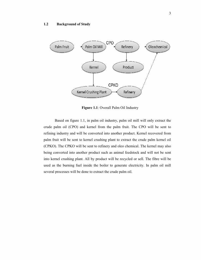
Figure 1.1: Overall Palm Oil Industry
Based on figure 1.1, in palm oil industry, palm oil mill will only extract the
crude palm oil (CPO) and kernel from the palm fruit. The CPO will be sent to
refining industry and will be converted into another product. Kernel recovered from
palm fruit will be sent to kernel crushing plant to extract the crude palm kernel oil
(CPKO). The CPKO will be sent to refinery and oleo chemical. The kernel may also
being converted into another product such as animal feedstock and will not be sent
into kernel crushing plant. All by product will be recycled or sell. The fibre will be
used as the burning fuel inside the boiler to generate electricity. In palm oil mill
several processes will be done to extract the crude palm oil.
3
n palm oil industry, palm oil mill will only extract the
crude palm oil (CPO) and kernel from the palm fruit. The CPO will be sent to
refining industry and will be converted into another product. Kernel recovered from
hing plant to extract the crude palm kernel oil
(CPKO). The CPKO will be sent to refinery and oleo chemical. The kernel may also
being converted into another product such as animal feedstock and will not be sent
ill be recycled or sell. The fibre will be
used as the burning fuel inside the boiler to generate electricity. In palm oil mill

4
Figure 1.2: Palm oil mill process
The palm oil processing units start with harvesting as shown in figure 1.2.
Harvesting involves the cutting of the bunch from the tree and allowing it to fall to
the ground by gravity. Fresh fruit arrives from the field as bunches or loose fruit.
Manual threshing is achieved by using a rotating drum or fixed drum equipped with
rotary beater bars detach the fruit from the bunch, leaving the spikelets on the stem.
The fruit is then sterilized. Sterilization or cooking means the use of high-
temperature wet-heat treatment of loose fruit causes the moisture in the nuts to
expand and leads to the detachment of the kernel from the shell wall, thus loosening
the kernels within their shells.

5
Digestion takes part after the sterilization process. Digestion is the process of
releasing the palm oil in the fruit through the rupture or breaking down of the oil-
bearing cells. There are two distinct methods of extracting oil from the digested
material. One system uses mechanical presses and is called the ‘dry’ method. The
other called the ‘wet’ method uses hot water to leach out the oil. The crude palm oil
from the presses contains a mixture of palm oil, water and fibrous materials in
varying proportions. It is pump to a continuous horizontal or vertical clarification
tank for oil separation.
The press discharge from the screw press consists of moist and oily fibre nuts
including broken ones and kernels. This mixture is conveyed to a Depericarper for
nut and fibre separation. The fibre and nuts are separated by a strong air current
induced by a suction fan. The air velocity has to be accurately determined for
efficient nut and fibre separation (Abdullah Ariffin and Mohd Nasir Hasan Basri,
1994).
Nut and kernel treatment consist of four distinct operations which are nut
conditioning, nut cracking, kernel and shell separation and kernel drying. For ideal
nut cracking, it is necessary to heat the nut to dry them sufficiently to loosen the
kernel ands and then cool the nut to harden the shell before cracking and this process
is referred as nut conditioning. Then it will be cracked using machine which are
almost invariably of the centrifugal type in which the nut are given velocity by being
fed through the rotor and are caused to crack by being flung against the stator ring
(Abdullah Ariffin and Mohd Nasir Hasan Basri, 1994).
There are some machine used for kernel and shell separation such as
winnowing, Wilder Dry separator, clay bath separator and hydrocyclone separator.
The kernel is the dried. The moisture content of fresh kernels is about 20% and if
bagged in this condition would soon become mouldy and in addition there would be
a rapid increase in the FFA of palm kernel oil (Abdullah Ariffin and Mohd Nasir
Hasan Basri, 1994).

6
1.3 Problem Statement
In separation of shell and fibre from kernel, palm oil mill normally employed
cyclone system. In the process, nut will enter depericarper to be separated from fibre
and then will enter either winnowing, wilder dry or hydrocyclone to separate its
shell. The similarity of all process used is it using cyclone system separator. The
inefficiency of cyclone is due to uneven of the inlet air flow rate. The amount of dirt
associated to kernel has contributed to the cyclone inefficiency; hence the separation
technique is not totally workable. Thus, inefficiency also causes less fibre to be
obtained for fuel purposes.
1.4 Objective of Research Project
The objective of the research project is to improve the efficiency of cyclone
separation of fibre and shell from kernel by manipulating the velocity of inlet air
flow rate, increase kernel production and increase the profit gain by the company.
1.5 Scope of Research Project
i. To study the effect of different velocity of air flow enter the cyclone.
ii. To study the separation process of fibre and shell from kernel.
iii. To study the oil and kernel losses in cyclone fibre.
iv. To study the effect of oil and kernel losses due to inefficient cyclone
v. To study the dirt removal in kernel recovery
vi. To study the effect of load amount on cyclone efficiency
7
CHAPTER 2
LITERATURE REVIEW
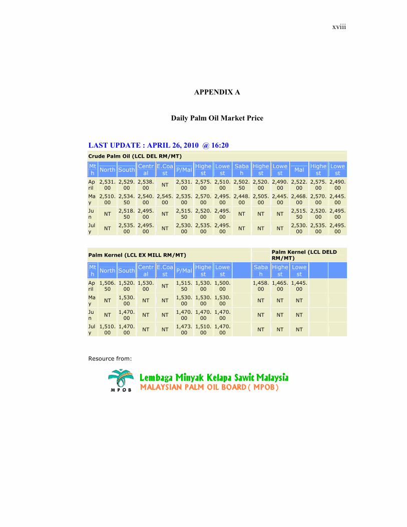
2.1 Oil palm fruit
The Palm tree fruit is various in form, size and character; sometimes, as in the
common date it is a berry with a fleshy rind enclosing a hard stony kernel, the true
seed; the fruit of Areca is similar; sometimes it is a kind of drupe as in Acrccomia, or
the coconut, Cocos nucif era, where the fibrous central portion investing the hard
shell corresponds to the fleshy portion of a plum or cherry, while the shell or nut
corresponds to the stone of stone-fruits, the seed being the kernel (Kalyana Sundram,
2009). In Borassus the three seeds are each enclosed in a separate chamber formed
by the stony endocarp. Sometimes, as in the species of Metroxylon, Raphia,
Daemonorops, &c,, the fruit is covered with hard, pointed, reflexed shining scales,
which give it a very remarkable appearance (Sundram K et al, 2003).
The oil palms (Elaeis) comprise two species of the Arecaceae, or palm
families which are used in commercial agriculture in the production of palm oil
(Kalyana Sundram, 2009). The African Oil Palm Elaeis guineensis is native to
west Africa, occurring between Angola and Gambia, while the American Oil
Palm Elaeis oleifera is native to tropical Central America and South America. The
generic name is derived from the Greek for oil, elaion, while the species name refers
to its country of origin. (Kalyana Sundram, 2009).
8
Mature trees are single-stemmed, and grow to 20 m tall.
The leaves are pinnate, and reach between 3-5 m long. A young tree produces about
30 leaves a year. Established trees over 10 years produce about 20 leaves a year.
The flowers are produced in dense clusters; each individual flower is small, with
three sepals and three petals (Sundram K et al, 2003).
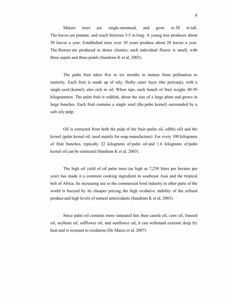
The palm fruit takes five to six months to mature from pollination to
maturity. Each fruit is made up of oily, fleshy outer layer (the pericarp), with a
single seed (kernel), also rich in oil. When ripe, each bunch of fruit weighs 40-50
kilogrammes. The palm fruit is reddish, about the size of a large plum and grows in
large bunches. Each fruit contains a single seed (the palm kernel) surrounded by a
soft oily pulp.
Oil is extracted from both the pulp of the fruit (palm oil, edible oil) and the
kernel (palm kernel oil, used mainly for soap manufacture). For every 100 kilograms
of fruit bunches, typically 22 kilograms of palm oil and 1.6 kilograms of palm
kernel oil can be extracted (Sundram K et al, 2003).
The high oil yield of oil palm trees (as high as 7,250 liters per hectare per
year) has made it a common cooking ingredient in southeast Asia and the tropical
belt of Africa. Its increasing use in the commercial food industry in other parts of the
world is buoyed by its cheaper pricing, the high oxidative stability of the refined
product and high levels of natural antioxidants (Sundram K et al, 2003).
Since palm oil contains more saturated fats than canola oil, corn oil, linseed
oil, soybean oil, safflower oil, and sunflower oil, it can withstand extreme deep fry
heat and is resistant to oxidation (De Marco et al, 2007)
9
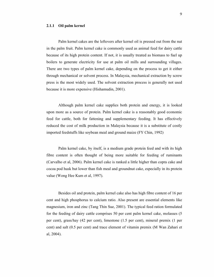
2.1.1 Oil palm kernel
Palm kernel cakes are the leftovers after kernel oil is pressed out from the nut
in the palm fruit. Palm kernel cake is commonly used as animal feed for dairy cattle
because of its high protein content. If not, it is usually treated as biomass to fuel up
boilers to generate electricity for use at palm oil mills and surrounding villages.
There are two types of palm kernel cake, depending on the process to get it either
through mechanical or solvent process. In Malaysia, mechanical extraction by screw
press is the most widely used. The solvent extraction process is generally not used
because it is more expensive (Hishamudin, 2001).
Although palm kernel cake supplies both protein and energy, it is looked
upon more as a source of protein. Palm kernel cake is a reasonably good economic
feed for cattle, both for fattening and supplementary feeding. It has effectively
reduced the cost of milk production in Malaysia because it is a substitute of costly
imported feedstuffs like soybean meal and ground maize (FY Chin, 1992)
Palm kernel cake, by itself, is a medium grade protein feed and with its high
fibre content is often thought of being more suitable for feeding of ruminants
(Carvalho et al, 2006). Palm kernel cake is ranked a little higher than copra cake and
cocoa pod husk but lower than fish meal and groundnut cake, especially in its protein
value (Wong Hee Kum et al, 1997).
Besides oil and protein, palm kernel cake also has high fibre content of 16 per
cent and high phosphorus to calcium ratio. Also present are essential elements like
magnesium, iron and zinc (Tang Thin Sue, 2001). The typical feed ration formulated
for the feeding of dairy cattle comprises 50 per cent palm kernel cake, molasses (5
per cent), grass/hay (42 per cent), limestone (1.5 per cent), mineral premix (1 per
cent) and salt (0.5 per cent) and trace element of vitamin premix (M Wan Zahari et
al, 2004).
10
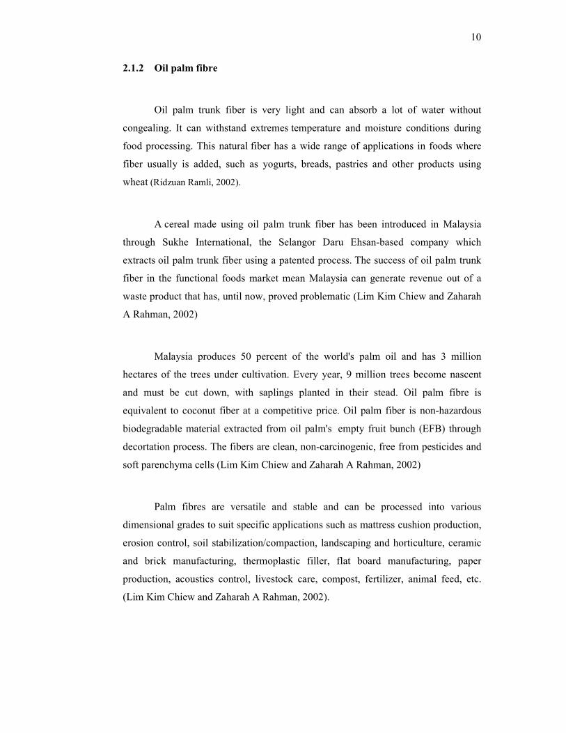
2.1.2 Oil palm fibre
Oil palm trunk fiber is very light and can absorb a lot of water without
congealing. It can withstand extremes temperature and moisture conditions during
food processing. This natural fiber has a wide range of applications in foods where
fiber usually is added, such as yogurts, breads, pastries and other products using
wheat (Ridzuan Ramli, 2002).
A cereal made using oil palm trunk fiber has been introduced in Malaysia
through Sukhe International, the Selangor Daru Ehsan-based company which
extracts oil palm trunk fiber using a patented process. The success of oil palm trunk
fiber in the functional foods market mean Malaysia can generate revenue out of a
waste product that has, until now, proved problematic (Lim Kim Chiew and Zaharah
A Rahman, 2002)
Malaysia produces 50 percent of the world's palm oil and has 3 million
hectares of the trees under cultivation. Every year, 9 million trees become nascent
and must be cut down, with saplings planted in their stead. Oil palm fibre is
equivalent to coconut fiber at a competitive price. Oil palm fiber is non-hazardous
biodegradable material extracted from oil palm's empty fruit bunch (EFB) through
decortation process. The fibers are clean, non-carcinogenic, free from pesticides and
soft parenchyma cells (Lim Kim Chiew and Zaharah A Rahman, 2002)
Palm fibres are versatile and stable and can be processed into various
dimensional grades to suit specific applications such as mattress cushion production,
erosion control, soil stabilization/compaction, landscaping and horticulture, ceramic
and brick manufacturing, thermoplastic filler, flat board manufacturing, paper
production, acoustics control, livestock care, compost, fertilizer, animal feed, etc.
(Lim Kim Chiew and Zaharah A Rahman, 2002).

11
In palm oil mill, the separated fibre from the fruit will be sent to boiler to
generate electricity. This process already been used by all palm oil mill in order to
save energy consumption. The electrical energy generated is enough to be used by
the mill. Burned fibre will remove from the boiler and may be converted into
fertilizer.
2.1.2 Oil palm Shell
Shell also known as endocarp is recovered from the nut after the nut cracking
using the cyclone. Shell will be used as the burning fuel along with the fibre. The
fibre is fully required in the mill for this purpose. However, only about 30% of shell
is utilized for this purpose (Abd Halim, 1985). Thus, the mills have generally excess
shell which is not used and which needs to be disposed of separately. Normally, shell
is about 10-11% from the fruit and it will not produce any oil.
Palm kernel shells have a very low ash and sulphur contents. Ash content
typical about 3% weight and sulphur content typical about 0,09% weight. Palm
kernel shells can be considered like a natural pellet and an high grade solid
renewable fuel for burning, as received, both in co firing with steam coal or burned at
biomass power plants, usually blended with other grades of biomass, like wood chips
(Abd Halim, 1985).
2.2 Equipment Used for Kernel Separation
2.2.1 Depericarper
The Depericarper consist of a rotating drum through which a current of air is
passed. The cake firm the matte breaking conveyor is fed in at one end of the drum
via a short closed length of conveyor, which acts as an air seal, and passes along the

12
drum. Lifting arms are fitted so that the nut and fibre are continually lifted up and
then fall down back to the drum (K.G Berger, 1989). Annular baffles slow doe the
movement of the nuts along the drum. A current of air passes through the drum in
the direction of the motion of the nuts and fibre and thus s induced by a powerful fan
mounted in the ducting above the separator at the outlet end. The air was originally
heated before it enters the drum, is sucked through the fan and then blown through
ducting to the cyclone. The nuts leaving the separator drum pass through smaller
rotating drum which is known as the polishing drum (K.G Berger, 1989).
Nuts from the depericarper drum will go to the polishing drum by elevator to
remove fibers from nuts. After the polishing drum, the de-stoner fan will sucks fibers
from nuts to the fiber cyclone, and nuts will go into the nut silos, then into nut
cracker (ripple mill) to crack the nuts, to get cracked mixtures. These cracked
mixtures will go through 2 winnowing systems (LTDS) for separation.
2.2.2 Low Tension Dust Separator
The low tension dust separator or the LTDS as it is popularly known can
contribute significantly toward the losses kernel, simply because of the separating
velocity of the separating column is set erratically and no one has the equipment to
measure it. By careful adjustment, the optimum velocity suitable for the cracking
mixture could be selected by adjusting the throat area of the separating column (Palm
oil Engineering Bulletin, 2009). Shells and kernels or cracked mixture which are
not 100% separated at the LTDS, conveyed to clay bath for further separation by
using vibrating screen (Kim Loong, 2007)

13
2.2.3 Hydrocyclone
In recent years, alongside the traditional use of hydrocyclones in mineral
processing, new applications, particularly in the field of environmental engineering,
have opened up for these separators (Neesse and Donhauser). A hydrocyclone is a
device to classify, separate or sort particles in a liquid suspension based on the
densities of the particles. A hydrocyclone may be used to separate solids from liquids
or to separate liquids of different density. A hydrocyclone will normally have a
cylindrical section at the top where liquid is being fed tangentially, and a conical
base. The angle, and hence length of the conical section, plays a role in determining
operating characteristics (K.G Berger, 1989).
The action of the hydrocyclone is somewhat similar o that an air cyclone in
that by imparting a circular motion to the fluid means of the tangential entry heavy
particles are thrown by centrifugal force to the wall of the cylinder and after tracing a
helical path find their way out through the bottom of the cyclone while lighter
particle after taking part in an initial downwards circular movement gradually move
towards the centre of the cylinder and start moving upwards leaving the cyclone via
the over flow tube (K.G Berger, 1989).
Internally, centrifugal force is countered by the resistance of the liquid, with
the effect that larger or denser particles are transported to the wall for eventual exit at
the reject side with a limited amount of liquid, whilst the finer, or less dense
particles, remain in the liquid and exit at the overflow side through a tube extending
slightly into the body of the cyclone at the center (Dyakowski et al, 1999)
Forward hydrocyclones remove particles that are denser than the surrounding
fluid, while reverse hydrocyclones remove particles that are less dense than the
surrounding fluid. In a reverse hydrocyclone the overflow is at the apex and the
underflow at the base. There is also parallel-flow hydrocyclones where both
accept and reject are removed at the apex. Parallel-flow hydrocyclones remove
particles that are lighter than the surround fluid (Neesse and Donhauser).

14
2.2.4 Clay bath Separator
Clay bath separator is the only method of separating the kernel form its shell
and fibre without using cyclone system. The specific gravity of the undried kernels is
about 1.07 and that of shell about 1.17 and therefore in a clay and water mixture of
specific gravity 1.12 kernels will float and shell will sink; this is the principle on
which the clay bath works. Many models were developed from the manually
operated to completely automatic versions. As suitable clays were not always readily
available salt solutions and even dilute molasses were tried for the suspension. The
clay bath is quite an efficient separator as long as the density of the suspension is
maintained at the correct value. However when processing the cracked mixture form
tenera nuts troubles can be experienced with a small long bearded nuts coming over
with the kernel (K.G Berger, 1989).
Clay bath separators tend to be rather messy and with the introduction of the
hydrocyclone separator and the clay bath soon dropped out of favour even though the
hydrocyclone need more power and capital outlays. Because of the heavy
maintenance cost and power demand associated with hydrocyclone there has been a
recent trend to adopt a winnowing system follow by a clay bath for a cracked mixture
separation (K.G Berger, 1989).
2.2.5 Cyclone
Cyclones are among the oldest types of industrial particulate control
equipment and are still one of the most widely used of all industrial gas-cleaning
devices (Bahrami et al, 2008). Cyclone separators are widely used in the field of
gas−solid separation for both engineering and process operations (Zhao Bing-tao,
2006). Their relative simplicity in fabrication, low cost in operation and well
adaptability to extremely harsh conditions make them, as important equipment,
especially useful in applications involving milling technologies for coal-fuelled
boilers in power plants (Zhao Bing-tao, 2006).
15
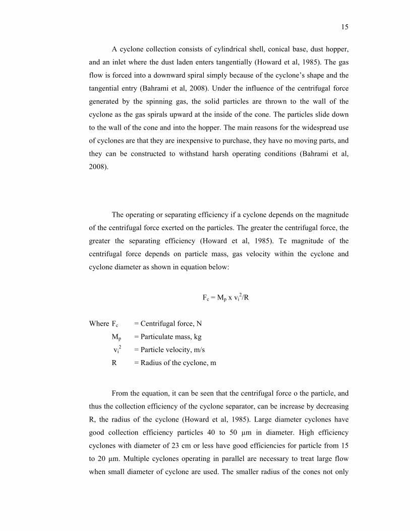
A cyclone collection consists of cylindrical shell, conical base, dust hopper,
and an inlet where the dust laden enters tangentially (Howard et al, 1985). The gas
flow is forced into a downward spiral simply because of the cyclone’s shape and the
tangential entry (Bahrami et al, 2008). Under the influence of the centrifugal force
generated by the spinning gas, the solid particles are thrown to the wall of the
cyclone as the gas spirals upward at the inside of the cone. The particles slide down
to the wall of the cone and into the hopper. The main reasons for the widespread use
of cyclones are that they are inexpensive to purchase, they have no moving parts, and
they can be constructed to withstand harsh operating conditions (Bahrami et al,
2008).
The operating or separating efficiency if a cyclone depends on the magnitude
of the centrifugal force exerted on the particles. The greater the centrifugal force, the
greater the separating efficiency (Howard et al, 1985). Te magnitude of the
centrifugal force depends on particle mass, gas velocity within the cyclone and
cyclone diameter as shown in equation below:
Fc = Mp x vi2/R
Where Fc = Centrifugal force, N
Mp = Particulate mass, kg
vi2 = Particle velocity, m/s
R = Radius of the cyclone, m
From the equation, it can be seen that the centrifugal force o the particle, and
thus the collection efficiency of the cyclone separator, can be increase by decreasing
R, the radius of the cyclone (Howard et al, 1985). Large diameter cyclones have
good collection efficiency particles 40 to 50 µm in diameter. High efficiency
cyclones with diameter of 23 cm or less have good efficiencies for particle from 15
to 20 µm. Multiple cyclones operating in parallel are necessary to treat large flow
when small diameter of cyclone are used. The smaller radius of the cones not only

16
increases the centrifugal force, but also reduces the distance the particles have to
travel to reach the collections chamber. Small cyclones do have some disadvantages,
such as problem with equalizing gas flow to each cone, abrasion of tubes due to high
velocity and plugging of heavily loaded tube. Cyclones usually build to standard
relative dimensions (Howard et al, 1985).
2.3 Cyclonic Separation
A full understanding of how the cyclone separator works and how individual
particles behave within it is not yet available (Hemdan Hanafy Shalaby, 2007).
Cyclones are one of the most common inertial devices and used for a variety of
applications, such as; ambient and source sampling and particulate matter control,
because of their simplicity of design, low maintenance costs, and adaptability to a
wide range of operating conditions (K.S.Lim et al, 2002).
The cyclone separator in its many is an old device which has been the subject
of many investigations. Evaluations of cyclone performance have long been studied
to better understand and improve cyclone design theory (Bahrami A. et al, 2008).
Basically the cyclone uses the flow through a nozzle or a set of blades to cause the
fluid within the cyclone chamber to rotate. This rotation develops a centrifugal force
field which tends to cause particles more dense than the fluid to move radially
outward from the center of rotation. Separation is affected by forcing the fluid to
move inward before it escapes from the cyclone chamber. The centrifugal separation
force on the particle is opposed by the drag due to the relative motion of the particle
through the fluid. The dense particle are either bled off with the small amount of
fluid or conveyed to a low velocity region where they settle out by gravity. The
rotating flow in the cyclone automatically and conveniently provides the conveying
flow (Joseph Le Conte Smith Jr, 1959)
Cyclonic separation is a method of removing particulates from an air, gas or
water stream, without the use of filters, through vortex separation. Rotational effects
17
and gravity are used to separate mixtures of solids and fluids. A high speed rotating
air flow is established within a cylindrical or conical container called a cyclone. Air
flows in a spiral pattern, beginning at the top (wide end) of the cyclone and ending at
the bottom (narrow) end before exiting the cyclone in a straight stream through the
center of the cyclone and out the top. Larger (denser) particles in the rotating stream
have too much inertia to follow the tight curve of the stream and strike the outside
wall, falling then to the bottom of the cyclone where they can be removed. In a
conical system, as the rotating flow moves towards the narrow end of the cyclone the
rotational radius of the stream is reduced, separating smaller and smaller particles.
The cyclone geometry, together with flow rate, defines the cut point of the cyclone.
This is the size of particle that will be removed from the stream with a 50%
efficiency. Particles larger than the cut point will be removed with a greater
efficiency and smaller particles with a lower efficiency.
A particle in the cyclonic flow will move towards either the wall of the
cyclone or the central axis of the cyclone until the drag, boyant and centrifugal forces
are balanced. Assuming that the system has reached steady state, the particles will
assume a characteristic radius dependent upon the force balance. Heavier, denser
particles will assume a solid flow at some larger radius than light particles. These
technologies demand high efficiency of cyclones to provide satisfactory and
economical performance, ensure regulatory compliance and protect expensive
downstream components (Zhao Bing-tao, 2006).
2.4 Collection Efficiency
Two important parameters in cyclone separator operation, collection
efficiency and pressure drop, are strongly influenced by the inlet particle
concentration (Zhongli Ji et al, 2008). Cyclones, however, have low collection
efficiency for small particles due to their reliance on inertial forces to separate
particles from gas streams. The need to improve their collection efficiency has lead
to a renewed interest in their design.
18
Cyclone collection efficiency is defined as the fraction of particles of a given
size that is retained by the cyclone (Fabio Luis Fassani and Leonardo Goldstein Jr,
1999). It also can be defined as the ratio between the mass of solids collected by the
cyclone in a time interval and the mass flow rate of incoming solids (Fabio Luis
Fassani and Leonardo Goldstein Jr, 1999).The theories that have been developed to
predict efficiency differ greatly in complexity. There is a general agreement that
operating parameters of the system should be used to predict performance and most
theories account for the influence of particle diameter and density and gas velocity
and viscosity (John Dirgo and David Leith, 1985).
Collection efficiency, the ratio of particles collected to particles injected, is
one of the most important parameters used in evaluating the performance of a
cyclone. If this ratio is applied to only a single particle diameter, it becomes the
grade or fractional efficiency. If this ratio is applied to only a single particle
diameter, it becomes the grade or fractional efficiency. If the particle volume fraction
or mass loading is low in a cyclone, particle transport is usually simulated using the
Lagrange approach in CFD analysis (Liming Shi and David J. Bayless, 2006).
The particle collection efficiency of a cyclone separator depends on its
geometric configuration, gas and particles physical properties, and on the operational
conditions (Fabio Luis Fassani and Leonardo Goldstein Jr, 1999). Patterson and
Munz (1996) studied the effects of concentration and flow temperature on the
collection efficiency of a 0.102 m diameter cyclone, operated with air temperatures
between 300 and 2000 K, inlet velocities from 3 to 42 m/s, and solid loadings up to
0.192 kg of solids/kg of gas. The increase of solid loading produced higher collection
efficiencies, a trend that was more noticeable for higher gas temperatures. Hoffmann
et al observed that the effect of solid loading was more pronounced for the lower
velocities they used. With loadings from 4.0×10⁻³
to 106.0×10⁻³
kg of solids/kg of
gas, Hoffmann et al noted an increase of the collection efficiency.
It is generally difficult to change the cut size in a conventional cyclone
separator. To solve this problem, researchers found that it is possible to change the
cut size by the use of a moving circular guide plate at the cyclone inlet or by the use

19
of an additional secondary flow injection method in the upper cylindrical part of
cyclone.
The efficiency of separation of cyclone separators depends on the centrifugal
field formed inside the cyclone separator. It is commonly known that the higher the
angular velocity of the gaseous medium flow, the more intensive is the centrifugal
field, and that the intensity of the centrifugal field is directly proportional to the
second power of the angular velocity of the medium flow. This is why small-
diameter cyclone separators are more efficient separators than cyclone separators of
larger diameter. It also comes from this that, in practical solutions, multi-cyclones are
adopted more and more frequently even though their investment cost and power
consumption are higher. In spite of this, cyclone separators are not capable of
meeting the requirements of good efficiency of separation (Viljo Jarvenpaa, 1999)
2.5 The separation of fibre from nut
The separation of the cake into its components gives rise to some difficulties
in case of processing of the selected fruit. As a result of the pressure exerted during
the extraction process except in the wet process, nut and fibre from the compact mass
which it is essential to break up prior to separation (Mangana Report, 1955).
The breaking up has been attempted in a mixer, in a cake breaker conveyor
and in an apparatus original conception working on the principle of the carding
machine. Only the cake conveyor gives complete satisfaction (Mangana Report,
1955). The effect of the speed of the rotation of the blades and of the diameter of the
through was studied. It appears from the experimental work that the breaking up only
occur beyond certain speed of rotation, for lower speed, the cake is simply churned
up without being teased (FY Chin, 1992)
Breaking up is easy in the case of continuous press cake which is well
extracted, has low cellular debris content and short fibrous strands. The cake derived

20
from extraction in a centrifuge has a higher oil and cellular debris content. For this
reason, it has a tendency to mass up into a lumps consisting of cellular debris
intimately mixed with long fibrous strands. This lump is very rare in the cake as it
comes out of the extraction equipment. They have the tendency to form as result of
handling, particularly in drum where the material tumbles over whilst being
subjected to rotation(Mangana Report, 1955).
2.6 Effect of load amount
The effect of loading is there could be a small increase of collection
efficiency with increasing loading, explained by the coarser particles carrying the
finer ones to the cyclone circumference, where they were collected (A.J. ter Linden,
1949). Correlated data from several sources and reported an increase in collection
efficiency with solid loading in the range of 1.868x10³ to 186.8x10
3 kg of solids/kg
of gas (Stern et al, 1955). Several particles and solid loadings up to 0.082 kg of
solids/kg of gas, with 15 and 20 m/s inlet velocities tested, observing the same trend
(Mori et al, 1968). For higher solid loadings, between 1.868x10³ and 1.868 kg of
solids/kg of gas also shows increasing collection efficiency, notably for the smaller
particles (Zenz, 1975).
The concentration and flow temperature also affect the collection efficiency
of a 0.102 m diameter cyclone, operated with air temperatures between 300 and 2000
K, inlet velocities from 3 to 42 m/s, and solid loadings up to 0.192 kg of solids/kg of
gas. The increase of solid loading produced higher collection efficiencies, a trend
that was more noticeable for higher gas temperatures (Patterson and Munz, 1989).
The effect of solid loading was more pronounced for the lower velocities they used.
With loadings from 4.0x10³ to 106.0x10
3 kg of solids/kg of gas, there are slightly
increase in the collection efficiency (Hoffmann et al, 1991).
No effect was observed for loadings varying from 0.3163x10³ to 41.0x10
3 kg
of solids/kg of gas (Fabio Luis Fassani and Leonardo Goldstein Jr, 1999).). As
concerns a cyclone operating in a circulating fluidized bed, a test carried out three in

21
a 0.406 m diameter separator, with solid loadings from 1.4 to 5.6 kg of solids/kg of
gas, and a gas entrance velocity of 3.6 m/s. The results indicated a reduction in
collection efficiency with increasing solid loading, markedly for smaller particles
(Tuzla and Chen, 1992). No variation in collection efficiency was found up to 0.816
kg of solids/kg of gas. In the range from 1.633 to 6.531 kg of solids/kg of gas a slight
efficiency increase was observed in tests carried out with 484 and 807 m average
diameter particles, but not in the 356 m particle tests (Fabio Luis Fassani and
Leonardo Goldstein Jr, 1999)
22
CHAPTER 3
METHODOLOGY
3.1 Introduction
The experiment will be tested on the effect of vary inlet air velocity of the
separation efficiency of the cyclone. The design of the cyclone cannot be adjusted.
Changing the cyclone will be costly. The particle load into the cyclone is always
kernel with vary size frequency. This test is conducted to prove that the vary air inlet
velocity give effect on the production of kernel and shell. Below are the steps
required for the test.

23
3.2 Procedure
Figure 3.1: Experimental methodology
3.2.1 Start up procedure
This step will be done by the machine operator at the Dominion Square Sdn.
Bhd. The cyclone needs to be operated before the test can be conducted. All the
equipment checked by the operator to make sure it can work properly. The foremen
will monitor the test.
Start up procedure
Load measurement
Inlet air flow
measurement and
adjustment
Product measurement
Analysis

24
3.2.2 Load measurement
The load will enter the cyclone after the nut cracker. The mass of load
entering the system are measured per unit time. At first, the time period proposed is
hour. It means the total load entering the cyclone for 1 hour will be measured. The
rejected and suggest that the load will be taken within 5 second due to too much load
will be produce in 1 hour and the process will be disturbed. The load is taken 3 times
and the average value is calculated. The load enter are measured regularly. Its data is
taken before the inlet air flow is changed, after changed and 1 hour after the change
which is before the product is measure.
3.2.3 Inlet air flow measurement and adjustment.
Using anemometer, the inlet air flow will be measured. The anemometer will
detect the air velocity in m/s along with the humidity and temperature. After the air
velocity is measured, let the system to run for 1 hour (except for the 1st data) before
the product is measured. This is because the time required for the process starting
from entering the cyclone until the last process before the sample can be taken
approximately 1 hour. The cracked nut is transferred into the system using a
conveyor with slow speed and the chain process for separation after the cyclone
including hydrocyclone and claybath make the time required increase.
3.2.4 Product measurement
The product will be measured using anemometer, a device to determine the
air velocity as the air pass through its detector. There are 2 products need to be
measure; kernel and shell. The products will also being taken 3 times and the average
is calculated. Same as the load, time period for the collection of product will be
within 5 seconds. The product at the kernel chamber will be checked before the
weight being measure. Any dirt such as small rock and shell will be removed first.
The product that should be measured is only the kernel. This indicates the separation
25
efficiency to get the pure kernel. Any change on the kernel production will affect the
efficiency. Higher kernel produce means the efficiency is high. The weight of the
shell product will be directly measure.
3.2.5 Analysis
Average data is calculated for each data taken. The test will be conducted
with different amount of load. The graph of kernel production versus air velocity will
be plotted for each load. The maximum air velocity will be determined from the
graph. The installment of additional cyclone fan to increase the inlet air velocity can
also be determined whether it is required or not. Any reduction of the kernel
production after the max point in graph indicates that the velocity is too high and the
addition of cyclone fan is not required.

26
CHAPTER 4
RESULT AND DISCUSSION
4.1 Result
4.1.1 Effect of inlet air velocity
Table 1 and 2 compare the load of cracked nuts entering the cyclone for
separation of kernel and shell at the rate is 0.4 kg/s and 0.3 kg/s respectively. The
entering load also contain small amount of fiber, small rock, and soil and will be
consider as dirt. As expected, the production of kernel and shell depend on the inlet
air velocity of the cyclone separator. The ideal inlet air velocity also changes if the
load entering is changed.
Table 4.1: Kernel and shell production with various air velocity for 0.4kg/s load
entering the cyclone separator
No Air velocity
(m/s)
Kernel
production (kg/s)
Shell Production
(kg/s)
1 9.0 0.16 0.06
2 10.0 0.19 0.06
3 11.0 0.20 0.08
4 11.5 0.24 0.08
5 12.0 0.20 0.12

27
Table 4.2: Kernel and shell production with various air velocity for 0.3kg/s load
entering the cyclone separator
No Air velocity
(m/s)
Kernel
production (kg/s)
Shell Production
(kg/s)
1 9.0 0.12 0.040
2 10.0 0.14 0.057
3 11.0 0.13 0.060
4 12.0 0.12 0.064
The current inlet air velocity used by the system at the plant is 11 m/s and the
current production of kernel and shell for 0.4 kg/s load is 0.2 kg/s and 0.08 kg/s
respectively. From the data, dirt of the current production is 0.12 kg/s. The
production of kernel and shell for 0.3 kg/s is 0.13 kg/s and 0.06 kg/s respectively and
the dirt is 0.11 kg/s. The dirt also contain small amount of cracked kernel and shell.
This due to the cracked kernel and small particle of shell which is lighter tends to
blown with the dirt inside the cyclone separator. The pattern of the data can be seen
in the graph below:
a) Kernel Production vs air velocity for 0.4 kg/s load.
b) Shell production vs air velocity for 0.4 kg/s load
c) Kernel Production vs air velocity for 0.3 kg/s load.
d) Shell Production vs air velocity for 0.3 kg/s load.

28
4.1.1.1 Kernel Production vs air velocity for 0.4 kg/s load.
Figure 4.1: Kernel Production vs air velocity for 0.4 kg/s load
Figure 1 shows the production of kernel with certain inlet air velocity. At the
beginning of the graph, the production of kernel increase as the inlet air velocity
increase. This pattern supports the fact that the efficiency of the cyclone separator
depend on the inlet air velocity. At 9 m/s inlet air velocity, the kernel production is
low due to the existence of some dirt and shell in the product. Production of kernel
increases gradually for each air velocity until 11.5 m/s which is the highest peak.
This peak is the best velocity which will give the high production of kernel due to
high efficiency. The production is decreasing after for 12 m/s. The kernels tend to
follow the inertia of the blown air if the air velocity is too high. In this case, 12 m/s
of inlet air velocity is too high for the system and will reduce its efficiency.
0
0.05
0.1
0.15
0.2
0.25
0.3
8 9 10 11 12 13
Ke
rne
l Pro
du
ctio
n (
kg
/s)
Air Velocity (m/s)
29
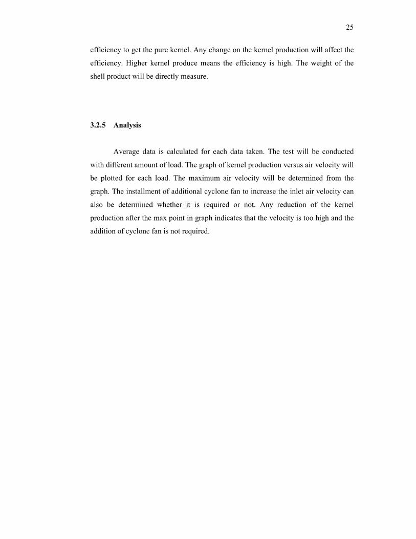
4.1.1.2 Shell production vs air velocity for 0.4 kg/s load.
Figure 4.2: Shell Production vs air velocity for 0.4 kg/s load
The productions of shells suppose to increase as the air velocity increase. The
experimental data as in figure 2 show the relation of the shell production and air
velocity. For 9 – 12 m/s air velocity, the production increase gradually. As for 12
m/s, the inlet air velocity is too high for the system. Total productions of shells
increase due to the addition of small or low density kernel which blown away inside
the cyclone separator and mix with the shell. At ideal inlet air flow rate (11.5 m/s),
the data only have slightly change of kernel production. It means that the highest
efficiency has already achieves between 11 m/s and 11.5 m/s for shell production.
0
0.02
0.04
0.06
0.08
0.1
0.12
0.14
8 9 10 11 12 13
Sh
ell
Pro
du
ctio
n (
kg
/s)
Air Velocity (m/s)
30
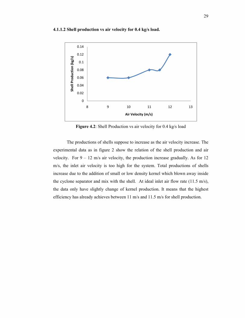
4.1.1.3 Kernel Production vs air velocity for 0.3 kg/s load.
Figure 4.3: Kernel Production vs air velocity for 0.3 kg/s load
Same compare to the graph pattern for load of 0.4 kg/s for kernel production,
this figure 3 graph pattern keep increasing until 1 point it will start to decrease. At 9
m/s air velocity, the efficiency is low which make the kernel production low due to
the production have many shell and some dirt. The ideal air velocity is at 10 m/s
which give 0.14 kg/s kernel production and highest efficiency. Higher inlet air
velocity to the system will reduce the separation efficiency and reduce the kernel
production. Current air velocity used by the cyclone at the plant is 11 m/s and it is
not the best velocity. 10 m/s air velocity should be used.
0.115
0.12
0.125
0.13
0.135
0.14
0.145
8 9 10 11 12 13
Ke
rne
l Pro
cud
tio
n (
kg
/s)
Air velocity (m/s)

31
4.1.1.4 Shell production versus air velocity for 0.3 kg/s load.
Figure 4.4: Shell Production vs air velocity for 0.3 kg/s load
Shell produce increase as the air velocity increase as shown in figure 4. At 9
m/s the production is low due to low efficiency. At ideal inlet air flow (10 m/s), the
pattern shows big changes in the production. For 10 m/s to 12 m/s, the production of
shell slightly increases. Increases in the air velocity after 10 m/s will make the kernel
inside the cyclone tend to follow the inertia and resulting increasing of shell
produced. This will make the kernel production decrease and so the efficiency of
separation will also decrease.
4.2 Discussion
4.2.1 Production Change
Table 4.3: Production change for 0.4 kg/s load
Current production/month After optimization Difference
518.4 MT/month 622.08 MT/month +103.68 MT/month
0
0.01
0.02
0.03
0.04
0.05
0.06
0.07
8 9 10 11 12 13
Sh
ell
Pro
du
ctio
n (
kg
/s)
Air Velocity (m/s)

32
Current inlet air velocity used by the system is 11 m/s. Using this speed by
assuming the load are constant in a month, the production of the kernel is 0.2 kg/s
and converting to month will become 518.4 MT/month. If the speed is adjusted into
11.5 m/s, the kernel production per month will increase to 622.08 MT/month. This
makes the difference of 103.68 MT/month production of kernel using different inlet
air flow.
Table 4.4: Production change for 0.3 kg/s load
Current production After optimization Difference
336.96 MT/month 362.88 MT/month +25.92 MT/month
For 0.3 kg/s load, the pattern is about the same where current inlet air
velocity just give the production of 336.96 MT/month kernels and the ideal inlet air
velocity which is 10 m/s will produce 263.88 MT/month. The difference is in
production is 25.92 MT/month. The difference is small due to lower load capacity
entering the system. This load capacity will only be process when there is shortage in
fruit supply due to palm fruit season (mainly in February).
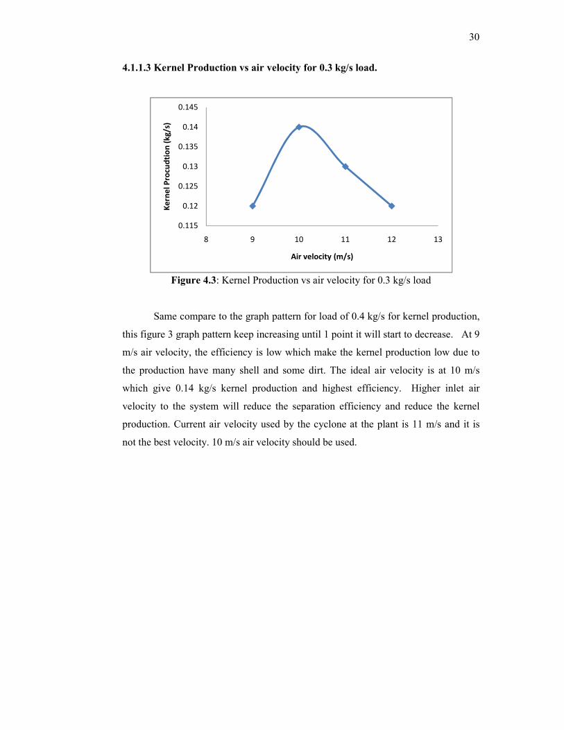
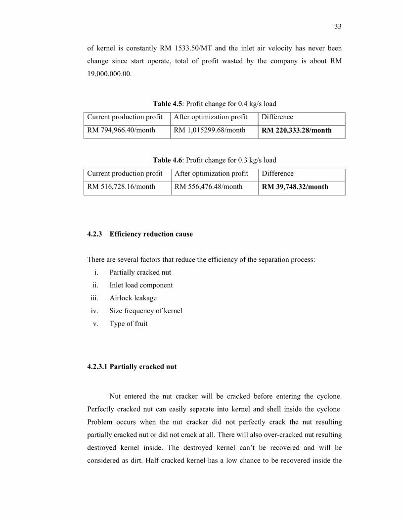
4.2.2 Profit change
From the Malaysian Palm Oil Board official website last update on 7 April
2010, kernel price for Mac 2010 is RM 1533.50/MT. Table below compare the price
of sold kernel according to load capacity. Current production of kernel for 0.4 kg/s
and 0.3 kg/s is RM 794,966.40/month and RM 516,728/month respectively. After the
optimization, the profit increase to RM 1,015,299.68/month and RM
556,476.48/month respectively. Load capacity of 0.4kg/s show large difference in the
profit of the kernel. The company can get more profit up to RM 220,333.28/month if
the best inlet air velocity is used by them. For 0.3 kg/s load, the profit difference
before and after optimization is way to smaller than 0.4 kg/s load but the value of
RM 39,748.32/month will still be considered as high. Considering from the company
start operate in January 2002 and assuming that the load is constantly 0.4kg/s, price
33
of kernel is constantly RM 1533.50/MT and the inlet air velocity has never been
change since start operate, total of profit wasted by the company is about RM
19,000,000.00.
Table 4.5: Profit change for 0.4 kg/s load
Current production profit After optimization profit Difference
RM 794,966.40/month RM 1,015299.68/month RM 220,333.28/month
Table 4.6: Profit change for 0.3 kg/s load
Current production profit After optimization profit Difference
RM 516,728.16/month RM 556,476.48/month RM 39,748.32/month
4.2.3 Efficiency reduction cause
There are several factors that reduce the efficiency of the separation process:
i. Partially cracked nut
ii. Inlet load component
iii. Airlock leakage
iv. Size frequency of kernel
v. Type of fruit
4.2.3.1 Partially cracked nut
Nut entered the nut cracker will be cracked before entering the cyclone.
Perfectly cracked nut can easily separate into kernel and shell inside the cyclone.
Problem occurs when the nut cracker did not perfectly crack the nut resulting
partially cracked nut or did not crack at all. There will also over-cracked nut resulting
destroyed kernel inside. The destroyed kernel can’t be recovered and will be
considered as dirt. Half cracked kernel has a low chance to be recovered inside the
34
cyclone. Mixture of all these kind of nut will reduce the separation efficiency.
Cyclone has low separation efficiency for small particle.
4.2.3.2 Inlet load component
Before entering the system, the nut will be crack using ripper mill resulting
mixture of kernel, shell and small amount of fiber. The efficiency will be reduced if
the are other component exist within the load. These particles mostly are soil and
small rock. The soil will be separated at the claybath process after the cyclone but the
rock will remain within the product. Small rocks will go either to shell product or
kernel product. It will not make any problem if the small rocks go to the shell but the
existence of small rock within the kernel will disturb the price of the kernel.
4.2.3.3 Airlock leakage
Cyclone airlock leakage will result in decreasing in cyclone collection
efficiency and decreasing in conveying velocity at the pickup point. Air leakage will
disturb the formation of centrifugal force inside the cyclone. As more air leak, the
centrifugal force inside the cyclone will reduce. Separating the load entering the
system may require higher centrifugal force. When leakage occurs, smaller particle
that suppose to be blown within the air will not have enough inertia and will be drop
into the wrong area. Total product at the kernel part will increase but the purity of
kernel will reduce due to existence of dirt. Kernel produce will have more shell.
Increase the inlet air velocity using additional cyclone fan will make thing worst
where another leakage may occur.
35
4.2.3.4 Size frequency of kernel
Separation is easy if the size of the kernels is same. But in reality, the size of
the each of the kernel is different. Its size may depend on the type of the fruit but nut
from the same type of fruit also produce difference size of kernel. Larger kernel will
be easy to be separated compare to the smaller kernel due to higher efficiency of the
cyclone to separate larger particle. Separation can be made using claybath because
the density of the kernel remains the same although the size is different. Inside the
cyclone, size of the kernel give has higher effect compared to the density.
4.2.3.5 Type of fruit
Types of fruit determine the size of the nut. Currently, companies used to
accept 2 type of palm fruit; Dura and Tenera. Dura has a high ratio of fibre, short
fibrous strands generally with high oil content, large size nuts with thick shell and
numerous multi kernel nuts. Tenera has a low ratio of nuts to fibre, long fibrous
strands generally with lower oil content and small size nuts with thin shell and a tuft
at one end. Dura has large nut but tenera has smaller nut. This difference in size will
slightly disturbing the nut cracking process. The kernel may not crack at all, partially
cracked or over-cracked. Ratio of kernel produce per load will be reduced.

36
CHAPTER 5
CONCLUSION AND RECOMMENDATION
5.1 Conclusion
The ideal inlet air velocity vary depend on the load entering the system. In
this company, the process mostly is 0.4 kg/s. Load will only reduce to 0.3 kg/s when
low fruit production season mostly on February every year. Current inlet air velocity
used by the company is 11 m/s and it was not being adjusted since 2002. For 0.4 kg/s
load, the best inlet air velocity is 11.5 m/s and for the 0.3 kg/s load, the best inlet air
velocity is 10 m/s. At this air velocity, the production of kernel and shell will
increase. As the production of shell increase, the burning fuel will increase.. As the
separation efficiency increase, the kernel product and quality will increase and the
profit will also increase. For 0.4 kg/s load, the company can get RM 220,333.28
more per month. The installation of additional cyclone fan does not give much
impact to the production of kernel and separation efficiency.
5.2 Recommendation
Separation efficiency of the kernel and shell can be increased if additional
separation process is done. Multi cyclone or another separation method such
hydrocyclone and claybath can be use after the first cyclone so the product will once
again gone through the separation process. Research can be made to set the
additional separation process to its max separation efficiency.
37
The inlet air flow rate should be adjusted according to the load enter. Load
indicator should be installed so the air velocity can easily be adjusted. If the load
indicator cannot be installed, manual measurement of the load also can be done by
the worker. The worker need to check the load enter regularly and adjust the inlet air
velocity if needed.
Efficiency of the nut cracker is low if the loads enter is high. So, reducing the
load inside the nut cracker will give a better cracking efficiency and reducing the
kernel losses. Reducing the nut entered the cracker may resulting the excess amount
of nut which need to be cracked. So additional nut cracker is recommended to
prevent this problem from occur.
It is also recommended to change the cyclone airlock because the leakage of
the airlock always occurs. If the leakage is noticed early by the worker, the
production and profit loss will be minimum. If it is not noticed early, the separation
efficiency will reduce for a long time and profit loss will be high. By changing the air
lock, this problem can be solved.
xiv
LIST OF REFERENCES
A.C. Hoffmann, H. Arends, H. Sie, (1991), Filtration and Separation, May–June,
page188–193.
A.C. Stern, K.J. Caplan, P.D. Bush, (1955), Cyclone Dust Collectors, American
Petroleum Institute, New York, NY, 67 pp.
A.J. ter Linden, (1949), Inst. Mech. Eng. J 150, pp. 233–251.
Abdullah Ariffin and Mohd Nasir Hasan Basri, (1995), Selected reading in palm oil
and its uses, Palm Oil Research Institute Malaysia.
Abdul Halim Shamsuddin, (1985), Energy conversation, Paper presented at Asian
Conference on Palm Oil byproducts as Alternative Energy Source, Kuala
Lumpur, 21-22 October.
Atakan Avci and Irfan Karagoz, (2003), Effects of flow and geometrical parameters
on the collection efficiency in cyclone separators, Journal of Aerosol Science
Volume 34, Issue 7, July, Pages 937-955.
Bahrami A. PhD , Qorbani F. Mahjub H. PhD, Aliabadi M., (2008), Effects of
Velocity and Particles Load on Efficiency of Cyclone in the Stone Crushing
Units at Azendarian Area, J Res health Sci, Vol. 8, No. 1, pp. 12-17.
Carvalho, Cabrita, Dewhurst, Vicente, Lopes, and Fonseca, (2006), Evaluation of
Palm Kernel Meal and Corn Distillers Grains in Corn Silage-Based Diets for
Lactating Dairy Cows , Journal of Dairy Science Vol. 89, No. 7.
xv
De Marco, Elena; Savarese; Parisini; Battimo; Falco; Sacchi, (2007), "Frying
performance of a sunflower/palm oil blend in comparison with pure palm
oil". European Journal of Lipid Science and Technology 109: 237.
F.A. Zenz, (1975), Manual on Disposal of Refinery Wastes: Volume on Atmospheric
Emissions, API Publication, 931.
Fábio Luís Fassani and Leonardo Goldstein Jr., (1998). A study of the effect of high
inlet solids loading on a cyclone separator pressure drop and collection
efficiency. Powder Technology, Volume 107, Issues 1-2, 24 January 2000,
Pages 60-65.
FY Chin, (1992), Palm Kernel Cake as a supplement for fattening and dairy cattle in
Malaysia , FAO, Manado, Chapter 25.
Hideto Yoshida, Yuta Inada, Kunihiro Fukui and Tetsuya Yamamoto, (2009),
Improvement of gas-cyclone performance by use of local fluid flow control
method, Powder Technology, Volume 193, Issue 1, 10 July, Pages 6-14
Hishamuddin Mohd Aspar, (2001), Malaysian Palm Kernel Cake as Animal
Feed ,Palm Oil Developments 34.
Howard S. Peavy, Donald R. Rowe, George Tcobanoglous, (1985), Environmental
Engineering, Mc-Graw Hill International Edition.
John Dirgo and David Leith (1985)'Cyclone Collection Efficiency: Comparison of
Experimental Results with Theoretical Predictions',Aerosol Science and
Technology,4:4,401 — 415.
Joseph Le Conte Smith Jr, (1959 ), Experimental and analytical study of the vortex in
cyclone separator, Massachusetts Institute of Technology.
K.G Berger, (1989), Symposium Proceedings of New Developments in Palm Oil,
Percetakan Hj Jantan, 19 Dec.

xvi
K.S.Lim, S.B.Kwon and K. W. Lee, (2002). Characteristics of the collection
efficiency for a double inlet cyclone with clean air. Journal of Aerosol
Science, Volume 34, Issue 8, August 2003, Pages 1085-1095.
K. Tuzla and J. Chen, (1992). AIChE Symposium Series, 88 pp. 130–136.
Kalyana Sundram PhD, (2009), Palm Oil: Chemistry and Nutrition Updates, MPOB.
Lim Kim Chiew and Zaharah A Rahma, (2002), The Effects Oil Palm Empty Fruit
Bunches on Oil Palm Nutrition and Yield, and Soil Chemical Properties,
Journal of Oil Palm Research Vol 14.
Liming Shi, David J. Bayless, (2007), Comparison of boundary conditions for
predicting the collection efficiency of cyclones, Powder Technology, Volume
173, Issue 1, 10 April, Pages 29-37.
M Wan Zahari and A R Alimon, (2004), Use of Palm Kernel Cake and Oil Palm By-
Products in Compound Feed, Palm Oil Developments 40.
Mangana Report, (1995), Research on Production and Storage of Palm Oil, Volume
2, MPOB publication.
Neesse, Th., Donhauser, F, Advances in the Theory and Practice of Hydrocyclone
Technique, University of Erlangen.
P.A. Patterson and R.J. Munz, (1989), The Canadian Journal of Chemical
Engineering 67, pp. 321–328
Palm Oil Engineering Bulletin, (2009), Malaysian Palm oil Board, Jan – March.
Patterson, P. A. and Munz, R. J. (1996) ,Gas and particle flow patterns in cyclones at
room and eleavated temperatures, Can. J. Chem. Eng., 74, pp.213-221.
Ridzuan Ramli, Stephen Shaler and Mohd Ariff Jamaludin, (2002), Properties Of
Medium Density Fibreboard From Oil Palm Empty Fruit Bunch Fibre, Journal
of Oil Palm Research Vol 14.

xvii
Shaohua Li, Yan Li, Jinjing Li, Shi Yang, Hairui Yang, Hai Zhang, Junfu Lu,
Guangxi Yue, (2009), Measurement of characteristics of solid flow in the
cyclone separators with fiber optical probe, Journal of Physics: Conference
Series 147.
Sundram K, Sambanthamurthi, Tan, (2003), Palm fruit chemistry and nutrition,
Asia Pacific journal of clinical nutrition 12 (3): 355–62.
T. Dyakowski, A.F Nowakowski, W. Kraipech and R.A. Williams, (1999), A Three
Dimensional Simulation of Hydrocyclone Behaviour, 2nd
International
Conference on CFD.
Tang Thin Sue, (2001), Quality and Characteristics of Malaysian Palm Kernel
Cakes/Expellers, Palm Oil Developments 34.
Viljo Jarvenpaa, (1999), Method and apparatus for improving the separation
efficiency of a cyclone separator intended for gaseous fluid flows, US Patent
Issued on January 12.
Wong Hee Kum, Wan Zahari Mohamed, (1997), Nutritive value of palm kernel cake
and cocoa pod husks for growing cattle, Journal of Tropical Agriculture and
Food Science, Vol. 25, No. 1, ISSN:1394-9829.
Y. Mori, A. Suganuma and S. Tanaka, (1968). Journal of Chemical Engineering of
Japan 1, pp. 82–86
Zhao Bing-tao, (2006), Effects of Flow Parameters and Inlet Geometry on Cyclone
Efficiency, The Chinese Journal of Process Engineering, Vol.6 No.2.
Zhongli Jia, Zhiyi Xionga, Xiaolin Wua, Honghai Chena and Hongxiao Wub,
(2007). Experimental investigations on a cyclone separator performance at an
extremely low particle concentration, Powder Technology,
Volume 191, Issue 3, 24 April 2009, Pages 254-259.
xviii
APPENDIX A
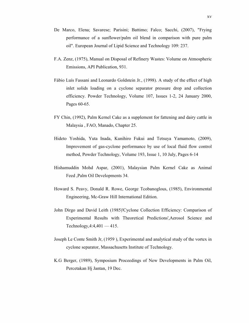
Daily Palm Oil Market Price
LAST UPDATE : APRIL 26, 2010 @ 16:20
Crude Palm Oil (LCL DEL RM/MT)
Mt
h North South
Centr
al
E.Coa
st P/Mal
Highe
st
Lowe
st
Saba
h
Highe
st
Lowe
st Mal
Highe
st
Lowe
st
April
2,531.00
2,529.00
2,538.00
NT 2,531.00
2,575.00
2,510.00
2,502.50
2,520.00
2,490.00
2,522.00
2,575.00
2,490.00
Ma
y
2,510.
00
2,534.
50
2,540.
00
2,545.
00
2,535.
00
2,570.
00
2,495.
00
2,448.
00
2,505.
00
2,445.
00
2,468.
00
2,570.
00
2,445.
00
Jun
NT 2,518.50
2,495.00
NT 2,515.50
2,520.00
2,495.00
NT NT NT 2,515.50
2,520.00
2,495.00
July
NT 2,535.00
2,495.00
NT 2,530.00
2,535.00
2,495.00
NT NT NT 2,530.00
2,535.00
2,495.00
Palm Kernel (LCL EX MILL RM/MT) Palm Kernel (LCL DELD
RM/MT)
Mt
h North South
Centr
al
E.Coa
st P/Mal
Highe
st
Lowe
st
Saba
h
Highe
st
Lowe
st
April
1,506.50
1,520.00
1,530.00
NT 1,515.50
1,530.00
1,500.00
1,458.00
1,465.00
1,445.00
May
NT 1,530.00
NT NT 1,530.00
1,530.00
1,530.00
NT NT NT
Jun
NT 1,470.00
NT NT 1,470.00
1,470.00
1,470.00
NT NT NT
Jul
y
1,510.
00
1,470.
00 NT NT
1,473.
00
1,510.
00
1,470.
00 NT NT NT
Resource from:

xix
APPENDIX B
Experimental Pictures
Figure B1: Cyclone in Industry
Figure B2: Flow of Air Inside Cyclone
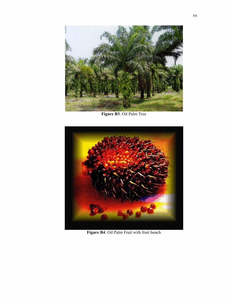
xx
Figure B3: Oil Palm Tree
Figure B4: Oil Palm Fruit with fruit bunch
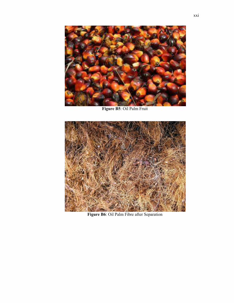
xxi
Figure B5: Oil Palm Fruit
Figure B6: Oil Palm Fibre after Separation
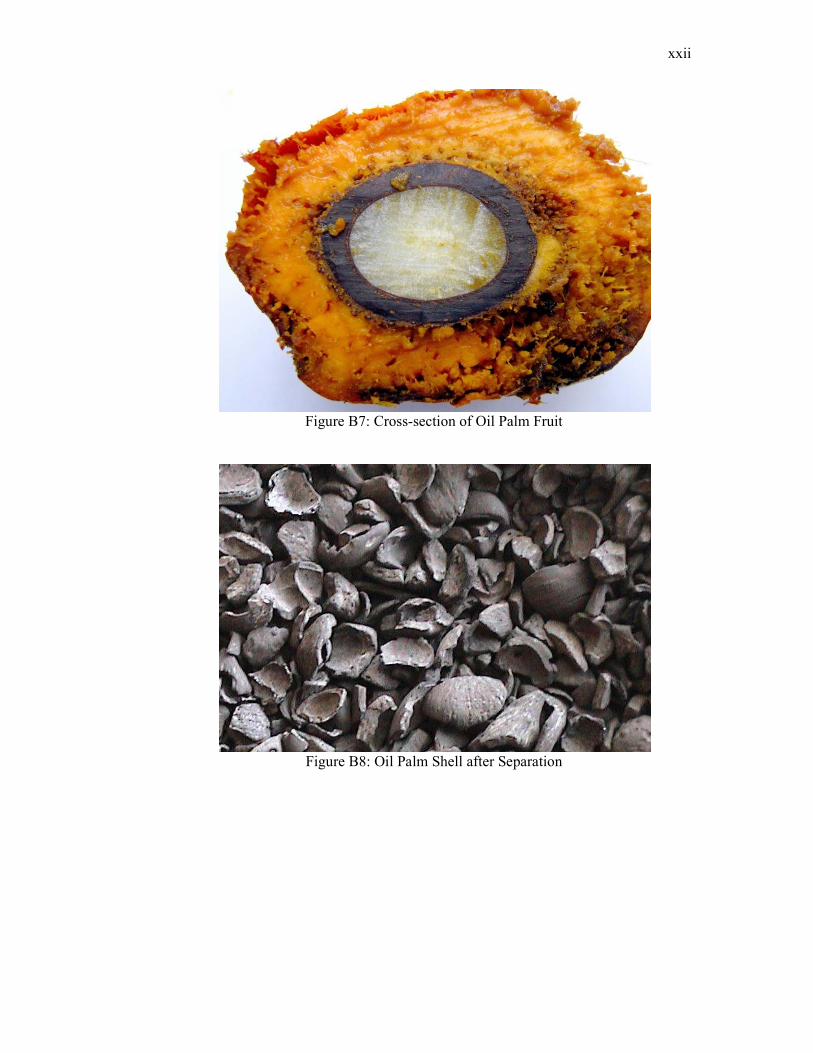
xxii
Figure B7: Cross-section of Oil Palm Fruit
Figure B8: Oil Palm Shell after Separation


