
Rack Mounted Oxygen Analyser
User Instruction Manual
Revision 0
Mullaghboy Industrial Park
Navan, Co. Meath, Ireland
Phone: 00-353-46-9071333 • FAX: 00-353-46-9071331
E-Mail: [email protected]
Web: www.ntron.com
The

OxyOne Manual/Rack Mount/Rev 0 Page 2/45

OxyOne Manual/Rack Mount/Rev 0 Page 3/45
Table Of Contents
TABLE OF CONTENTS ............................................................................................................................................ 3
I. CAUTIONS AND WARNINGS ....................................................................................................................... 5
A. WARNINGS ....................................................................................................................................................... 5 B. CAUTIONS ......................................................................................................................................................... 5
II. INTRODUCTION ............................................................................................................................................ 7
A. FEATURES ........................................................................................................................................................ 7 B. HARDWARE DESCRIPTION ................................................................................................................................ 8
1. Rack Mount System ................................................................................................................................... 8 2. Analyser Module ..................................................................................................................................... 10 3. Power Supply Module ............................................................................................................................. 10 4. Non-Intrinsically Safe Terminal Block & RelayGroup ........................................................................... 10 5. Intrinsically Safe Barrier Interface Devices ........................................................................................... 10
III. DOCUMENTATION NOTES ..................................................................................................................... 11
IV. SYSTEM INSTALLATION ......................................................................................................................... 13
A. MOUNTING .................................................................................................................................................... 13 B. WIRING DETAILS ........................................................................................................................................... 13
1. TB1 - Mains Power Input Terminal Group ............................................................................................ 13 2. TB2 – Non Intrinsically Safe Terminal block & Relay Group ................................................................ 14 3. Intrinsically Safe Barrier Interface Wiring ............................................................................................ 15
V. START UP PROCEDURES .......................................................................................................................... 17
A. SAMPLE PACKAGE/SENSOR INSTALLATION AND START UP ........................................................................... 17 B. INITIAL SYSTEM POWER UP ........................................................................................................................... 17 C. THE MENU STRUCTURE ................................................................................................................................. 18 D. MAIN MENU SUB-DIVISION & PASSWORD STEPS. ......................................................................................... 20 E. THE CALIBRATION MENU .............................................................................................................................. 21
1. Calibration Routine ................................................................................................................................ 21 2. Calibration Gas Concentration .............................................................................................................. 22 3. Transition Lag Time ............................................................................................................................... 23 4. Flow-Switch Check: ................................................................................................................................ 23 5. AutoCalibration. ..................................................................................................................................... 23 6. Verification ............................................................................................................................................. 24
F. THE CONFIGURATION MENU .......................................................................................................................... 25 1. Adjust Oxygen Action Levels .................................................................................................................. 25 2. Simulation ............................................................................................................................................... 28 3. Damping ................................................................................................................................................. 28 4. Adjust Blow Back Control ...................................................................................................................... 28 5. Set Date/Time ......................................................................................................................................... 29 6. Assign Name Tags to Channel ................................................................................................................ 29
G. THE PROGRAMMING MENU ........................................................................................................................... 30 1. Program Relays 1-8 ................................................................................................................................ 30 2. Passwords ............................................................................................................................................... 32 3. Calibration Due ...................................................................................................................................... 33

OxyOne Manual/Rack Mount/Rev 0 Page 4/45
A. NORMAL OPERATION ..................................................................................................................................... 35 B. CALIBRATION MODES .................................................................................................................................... 35 C. 4-20MA OUTPUT CURRENT LOOP SIGNALS ................................................................................................... 35 D. ALARM RELAY CONTACT SETS ..................................................................................................................... 35 E. ANALYSER MESSAGES ................................................................................................................................... 35
1. Levels Normal ......................................................................................................................................... 35 2. No Flow .................................................................................................................................................. 36 3. Calibration Due ...................................................................................................................................... 36 4. Level Alarms ........................................................................................................................................... 36 5. Stabilising ............................................................................................................................................... 36 6. Cal Fail #1 .............................................................................................................................................. 37 7. Input Fault .............................................................................................................................................. 38 8. Range Error ............................................................................................................................................ 38 9. Maintenance/Maintenance Required ...................................................................................................... 38 10. Blowback ............................................................................................................................................ 39
VII. MAINTENANCE PROCEDURES ............................................................................................................ 41
A. FACTORY ASSISTANCE OR ANALYSER RETURN FOR FACTORY SERVICE ....................................................... 41 B. TROUBLESHOOTING GUIDELINES ................................................................................................................... 41
1. Wiring Faults. ......................................................................................................................................... 41 2. Sensor Old, Sensor Bad Message. .......................................................................................................... 41 3. Flow Related Fault Messages. ................................................................................................................ 41 4. System Maintenance Alarm Relay Contact. ............................................................................................ 42 5. System Fault Alarm Relay Contact. ........................................................................................................ 42 6. One Relay Contact Constantly in Alarm State. ....................................................................................... 42 7. Sensor Guard. ......................................................................................................................................... 42 8. 4-20mA Current Output is in its Fault State. .......................................................................................... 42
C. SPARE PARTS LISTING.................................................................................................................................... 42
VIII. SPECIFICATION LISTING .................................................................................................................... 43
IX. WARRANTY STATEMENT ....................................................................................................................... 45
OxyOne Manual/Rack Mount/Rev 0 Page 5/45
I. Cautions and Warnings
A. Warnings
This analyser is rated for location in area atmospheres that are classified as non-hazardous only. Location in
area atmospheres rated other than non-hazardous may result in fire or explosion dangers.
The user of this equipment assumes full responsibility for meeting all local electrical and construction codes
during installation and operation of the system.
The analyser system interfaces with chemical fuel cell oxygen sensors that are self-depleting. The oxygen
sensors will typically expire and require replacement every six (6) to twelve (12) months. Failure to maintain
oxygen sensor(s) as referenced in this manual will result in system failure or error.
The analyser enclosure is not sealed. The enclosure should not be subjected to immersion in liquids, exposed
to continued jets or sprays of liquids, or purposely hosed down. Continued exposure to liquids may lead to
leakage of liquids internal to the enclosure and result in system damage.
The analyser interface wiring may require the use of intrinsically safe wiring devices. The use of intrinsically
safe wiring devices is required whenever wiring from the analyser will be routed into an area containing
hazardous gas, dust or fibers. Use only the devices specified by this manual or any other documentation
supplied for the specific analyser. Use of other devices or the non-use of devices when required will void all
warranties and may result in severe damage to the instrument or the facility in which it is installed.
This instrument is provided with user configurable alarm setpoints. The user assumes full responsibility for
the determination and maintenance of required alarm setpoints.
Read this manual in its entirety and fully understand all aspects of the analyser before attempting installation,
start up, operation or maintenance of the analyser.
B. Cautions
The analyser shall be mounted in a fashion that will guard against excessive vibration, collapse, exposure to
liquids or in an area atmosphere that is not rated as non-hazardous.
The user shall refer to the user instructions supplied with the associated sensor or sampling system for
additional warnings and cautions.
This analyser has been designed to interface with sensors and sampling systems supplied by Ntron only. No
attempt should be made to interface the analyser with any other sensor or sampling system without
consultation with Ntron Ltd.
The oxygen sensor fuel cells utilised with Ntron systems may have adverse reactions to certain chemical
compounds. It is the full responsibility of the user to disclose all of the anticipated chemical compounds that
may be encountered in the utilization of the system to Ntron. Failure to disclose the chemical compounds that
may be encountered may result in system errors or failures and will not be covered under any warranty
expressed by Ntron, Ltd.
This analyser is a microprocessor-based instrument and is sensitive to static discharges and interference from
RFI and EMI emissions. The analyser has been designed to minimize all effects of the aforementioned
conditions. When wiring the analyser in the field, the user must minimize the amount of wiring placed
adjacent to the analyser and shall not lay extra lengths of wire on or around any part of the analyser.
OxyOne Manual/Rack Mount/Rev 0 Page 6/45
The analyser is supplied with user configurable password protection software. The user should exercise
caution in the release of selected passwords to prevent the unwarranted revision of system configurations and
setpoint adjustments.
Before installing the analyser, the user should verify that the power requirement stated in this manual matches
the power service of the specific location. Attempts to utilise the analyser on power service other than what
is specified by the power identification label will result in instrument damage.
The analyser contains intrinsically safe wiring locations next to non-intrinsically safe wiring locations
physically separated by a non-conductive barrier plate. In no circumstances should the user attempt to
breach the barrier plate and wire intrinsically safe conductors to non-intrinsically safe components or
wire non-intrinsically safe conductors to intrinsically safe components. Failure to properly connect rated
conductors to the proper components may result in explosion or fire hazards.

OxyOne Manual/Rack Mount/Rev 0 Page 7/45
II. Introduction
A. Features
The OxyOne Analyser is a microprocessor based instrument. It is capable of accepting multiple sensor inputs
from Ntron designed sensors or sampling systems and utilizing these inputs to control user configurable alarms
and signal outputs. Eight (8) alarm relay single-pole, double-throw contacts are provided to alert the user of
conditions such as calibration sequences, setpoint activation, system maintenance requirements, system fault
conditions and sensor comparison alarms. An isolated 4-20mA current loop is provided to correspond to the
sensed concentrations of the oxygen sensor.
User interface is provided by a 5.7” (QVGA) TFT LCD, white LED backlight “resistive” touchscreen that will
convey system status, system prompts and system configuration to the user.
The analyser will allow user configuration of the system to specific user applications. Variables that are user
configurable include date and time setting, alarm setpoint setting, calibration and time, calibration alarm
variables, “what-if” scenario exercises, channel tag creation and password entries.
Password protection is provided by the analyser in a three level setup. The first, or level one password will
provide access to the calibration menu. The second level of security, which is also password protected by either
a different or the same password as the first level, will provide access to both the configuration & program
system menu’s. The final level of security is provided as a “backdoor” password that allows access to the
Engineer menu, it is only available at the factory or from an authorized Ntron distributor. This password is
utilised during product manufacturing & system configuration, calibration and testing as well as emergency field
situations.
Designed to interface directly with Ntron supplied sensors or sampling systems, the analyser requires an oxygen
sensor to operate. Sampling packages will vary. Sample systems will include a flow switch, and may have a
redundant sensor. The analyser is equipped to direct and control the automatic calibration of the sensor or
sampling system through a remotely located solenoid valve. All electrical interfacing with the sensors or
sampling systems is made by the user through connection points supplied with the analyser.
The analyser has been designed to interface with fuel cell oxygen sensors. A common problem with fuel cells is
that they fail into a ‘safe’ condition. The OxyOne has several features to address this situation. The auto-
calibration feature will check the sensor on a daily basis. This provides information to the “sensor life” predictor
function. This function is displayed as a bar graph in the calibration menu. Information gained from the sensors
output during calibration will up-date this bar graph. When the sensors “life remaining” approaches 15% of the
minimum reliable calibration output it will trigger a warning for maintenance. The “Sensor Guard” feature can
be selected to increase automatic calibration frequency, if sensor output falls below a selectable oxygen
concentration.
All electrical circuits, factory wiring and interface devices are close coupled to 4U full width 19” rack plate. This
rack plate is suitable for mounting within an industry standard 19” rack system.
The OxyOne Analyser provides flexibility for use in various applications with the same reliability and accuracy
that has been consistent with the Ntron name.
OxyOne Manual/Rack Mount/Rev 0 Page 8/45
B. Hardware Description
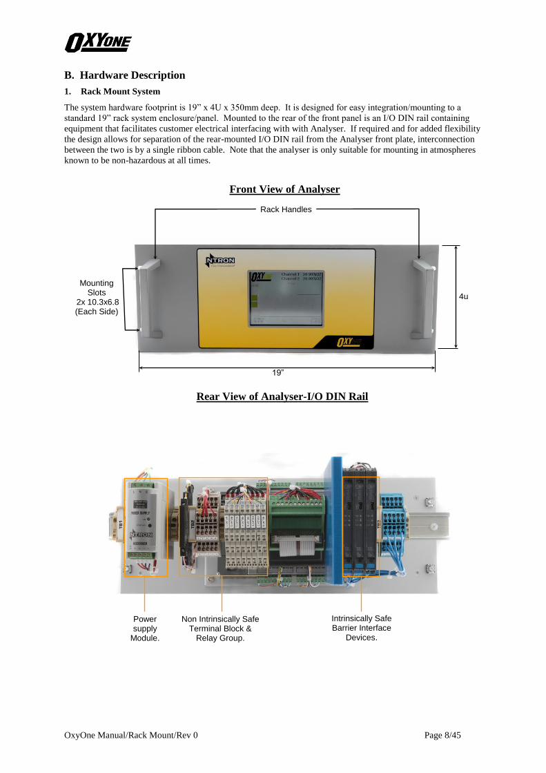
1. Rack Mount System
The system hardware footprint is 19” x 4U x 350mm deep. It is designed for easy integration/mounting to a
standard 19” rack system enclosure/panel. Mounted to the rear of the front panel is an I/O DIN rail containing
equipment that facilitates customer electrical interfacing with with Analyser. If required and for added flexibility
the design allows for separation of the rear-mounted I/O DIN rail from the Analyser front plate, interconnection
between the two is by a single ribbon cable. Note that the analyser is only suitable for mounting in atmospheres
known to be non-hazardous at all times.
Front View of Analyser
Rear View of Analyser-I/O DIN Rail
Rack Handles
Mounting Slots
2x 10.3x6.8 (Each Side)
19”
4u
Power supply
Module.
Non Intrinsically Safe Terminal Block &
Relay Group.
Intrinsically Safe Barrier Interface
Devices.

OxyOne Manual/Rack Mount/Rev 0 Page 9/45
Rear View of Analyser-Analyser - I/ O DIN Rail & Analyser Module
Analyser-Alternative Mounting Arrangement
Mount to 19” Rack Panel/Enclosure rear
Backplate via brackets provided
Mount to front of 19” Rack Panel/Enclosure
Interconnecting Ribbon cable
Detail As Indicated Above
Analyser Module
OxyOne Manual/Rack Mount/Rev 0 Page 10/45
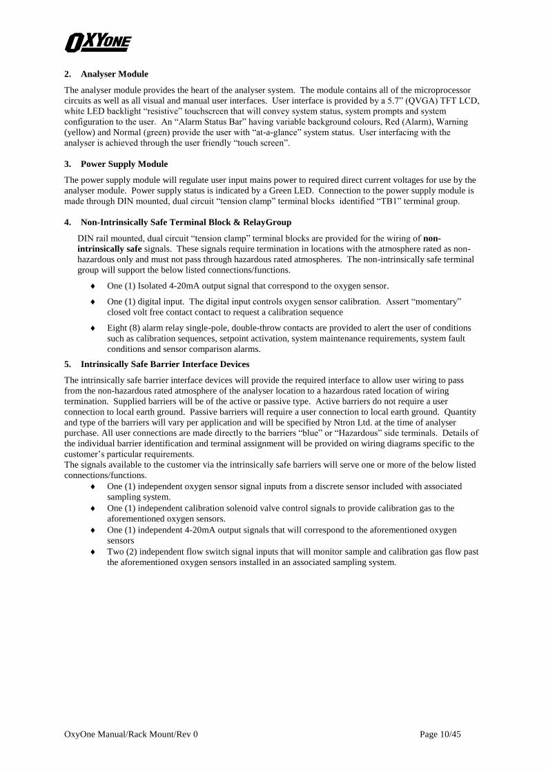
2. Analyser Module
The analyser module provides the heart of the analyser system. The module contains all of the microprocessor
circuits as well as all visual and manual user interfaces. User interface is provided by a 5.7” (QVGA) TFT LCD,
white LED backlight “resistive” touchscreen that will convey system status, system prompts and system
configuration to the user. An “Alarm Status Bar” having variable background colours, Red (Alarm), Warning
(yellow) and Normal (green) provide the user with “at-a-glance” system status. User interfacing with the
analyser is achieved through the user friendly “touch screen”.
3. Power Supply Module
The power supply module will regulate user input mains power to required direct current voltages for use by the
analyser module. Power supply status is indicated by a Green LED. Connection to the power supply module is
made through DIN mounted, dual circuit “tension clamp” terminal blocks identified “TB1” terminal group.
4. Non-Intrinsically Safe Terminal Block & RelayGroup
DIN rail mounted, dual circuit “tension clamp” terminal blocks are provided for the wiring of non-
intrinsically safe signals. These signals require termination in locations with the atmosphere rated as non-
hazardous only and must not pass through hazardous rated atmospheres. The non-intrinsically safe terminal
group will support the below listed connections/functions.
One (1) Isolated 4-20mA output signal that correspond to the oxygen sensor.
One (1) digital input. The digital input controls oxygen sensor calibration. Assert “momentary”
closed volt free contact contact to request a calibration sequence
Eight (8) alarm relay single-pole, double-throw contacts are provided to alert the user of conditions
such as calibration sequences, setpoint activation, system maintenance requirements, system fault
conditions and sensor comparison alarms.
5. Intrinsically Safe Barrier Interface Devices
The intrinsically safe barrier interface devices will provide the required interface to allow user wiring to pass
from the non-hazardous rated atmosphere of the analyser location to a hazardous rated location of wiring
termination. Supplied barriers will be of the active or passive type. Active barriers do not require a user
connection to local earth ground. Passive barriers will require a user connection to local earth ground. Quantity
and type of the barriers will vary per application and will be specified by Ntron Ltd. at the time of analyser
purchase. All user connections are made directly to the barriers “blue” or “Hazardous” side terminals. Details of
the individual barrier identification and terminal assignment will be provided on wiring diagrams specific to the
customer’s particular requirements.
The signals available to the customer via the intrinsically safe barriers will serve one or more of the below listed
connections/functions.
One (1) independent oxygen sensor signal inputs from a discrete sensor included with associated
sampling system.
One (1) independent calibration solenoid valve control signals to provide calibration gas to the
aforementioned oxygen sensors.
One (1) independent 4-20mA output signals that will correspond to the aforementioned oxygen
sensors
Two (2) independent flow switch signal inputs that will monitor sample and calibration gas flow past
the aforementioned oxygen sensors installed in an associated sampling system.
OxyOne Manual/Rack Mount/Rev 0 Page 11/45
III. Documentation Notes
The user is supplied with this manual as a base reference to system installation, configuration, start up,
operation and maintenance.
It is not practical to describe all possible options and configurations herein. However additional
documentation, supplied under separate cover, will provide “system specific” details that will depict specific
system installation electrical hook-up and configuration and will includes all devices supplied by Ntron, such
as sensors, sampling systems, pre-conditioning sampling components, etc relevant to analyser package
ordered by the customer.
Should the user misplace or damage the documentation, replacements are available directly from Ntron, Ltd.,
Have the document number ready when requesting replacement. Direct calls to Ntron, Ltd. may be made
during normal business hours (9AM – 5PM, Monday through Friday) or at any time through FAX or email
correspondence.
To Replace Missing or Damaged Documentation, Contact:
Ntron, Ltd.
Mullaghboy Industrial Park
Navan, Co. Meath, Ireland
Phone: 00-353-46-9071333
FAX: 00-353-46-9071331
E-Mail: [email protected]
Web: www.ntron.com

OxyOne Manual/Rack Mount/Rev 0 Page 12/45

OxyOne Manual/Rack Mount/Rev 0 Page 13/45
IV. System Installation
A. Mounting
Select the preferred mounting location for the analyser. The location should provide ease of user access and
viewing of the display features and should be in an area away from contact with liquid sprays, liquid jets or
liquid submersion. The location of the analyser must have an atmospheric rating as non-hazardous at all
times. The analyser is not equipped to be located in atmospheres that may be rated as hazardous at any time.
Warning: The analyser MUST be located in atmospheres that are rated as non-hazardous at all times.
Mounting of the analyser in locations that are not rated as non-hazardous at all times may result in fire or
explosion danger.
Mounting of the instrument is achieved through four 10.3 mm x 6.8 mm diameter (.40” x .27”) mounting
slots located on the front of the enclosure. Mount the instrument through a wall or into an existing control
room rack.
B. Wiring Details
This section of the manual will describe the generic wiring connections to the analyser.
Customised analysers may have wiring requirements that differ from the content of this manual. For
customized analysers refer to the custom documentation supplied with the analyser.
Warning: The user bears full responsibility for meeting all local electrical codes when installing and
wiring the analyser.
Note: Make all connections internal to the analyser with a minimum length of wire. Leaving coils or extra
lengths of wire adjacent to the analyser may increase the analyser sensitivity to EMI/RFI interference.
1. TB1 - Mains Power Input Terminal Group
Mains power is to be wired to the TB1 terminal block. The voltage requirement is 85-260 VAC @ 47-63 Hz.
with an equivalent power consumption of 0.56A (Max) @ 115VAC or 0.33A (Max) @ 230VAC.
Note: The TB1 terminal block are of the “tension clamp” type and required a terminal screwdriver to
operate the clamping mechanism.
Connections to the block are as follows:
Terminal 1: Earth
Terminal 2: Live
Terminal 3: Neutral
TB1 TB2 Relay
Interface I.S. Barrier Interface
No Customer Connection This Side
See Below For More Detail
OxyOne Manual/Rack Mount/Rev 0 Page 14/45
2. TB2 – Non Intrinsically Safe Terminal block & Relay Group
This terminal block group is subdivided as follows, analogue - digital I/O & relay group, details as follows.
Note: The TB2 terminal block are of the “tension clamp” type and required a terminal screwdriver to
operate the clamping mechanism.
Analogue & Digital Terminal Group Pin Out Listing:
Pin 4: 4-20mA Loop, Positive (+)
Pin 5: 4-20mA Loop, Negative (-)
Pin 6: Digital Input, (Calibration Request)
Pin 7: Digital Input, (Calibration Request)
Pin 8: Digital Input, (Spare)
Pin 9: Digital Input, (Spare)
Relay Group Wiring
All connections to the alarm relay contact sets are made to the R1 through R8 relay blocks.
Note: The relay connections are of the “tension clamp” type and required a terminal screwdriver to
operate the clamping mechanism.
The relay designation of each terminal block is listed below. Note that each terminal block carries the
same normally open, common, and normally closed pin out configuration as listed below. The function
of each relay will be determined by the analyser configuration set by or specified by the user.
Warning: Hazardous high voltage wiring shall be bundled and separated from low voltage wiring
with a minimum clearance of 6.5mm to ensure safe operation.
Relay Pin Out Configuration:
Pin 11: Common
Pin 12: Normally Closed
Pin 14: Normally Open

OxyOne Manual/Rack Mount/Rev 0 Page 15/45
3. Intrinsically Safe Barrier Interface Wiring
The barrier interface devices are supplied as specified at time of analyser purchase. Therefore, the
specific analyser may not have all of the barriers described within this manual. However additional
documentation, supplied under separate cover will provide “system specific” details that will depict
electrical hook-up and configuration relevant to the analyser package ordered by the customer.
All wiring to the barriers is to be considered intrinsically safe and all safeguards required by local
electrical codes must be met. Wire connections are to be made to the removable terminal blocks of each
barrier as specified below. Note that signal wiring, such as oxygen sensor and 4-20mA, should be made
through twisted pairs from the barrier to the ultimate termination point.
Single Channel Sensor Barrier Pin Out Listing (GMI D1010S):
Pin 15: Negative (-)
Pin 16: Positive (+)
Dual Channel Sensor Barrier Pin Out Listing (GMI D1010D):
Pin 11: Negative (-)
Pin 12: Positive (+)
Single Channel Flow Switch Barrier Pin Out Listing (GMI D1030S):
Pin 13: Positive (+)
Pin 14: Negative (-)
Dual Channel Flow Switch Barrier Pin Out Listing (GMI D1030S):
Pin 15: Positive (+)
Pin 16: Negative (-)
4 Channel Solenoid Barrier Pin Out Listing (GMI D1042Q):
Channel 1 Pin 13 & 15: Positive (+)
Pin 14 & 16 Negative (-)
Channel 2 Pin 9 & 11: Positive (+)
Pin 10 & 12: Negative (-)
4-20mA Barrier Pin Out Listing (GMI D1020S):
Pin 15: Positive (+)
Pin 16: Negative (-)

OxyOne Manual/Rack Mount/Rev 0 Page 16/45
OxyOne Manual/Rack Mount/Rev 0 Page 17/45
V. Start Up Procedures
After completing analyser mounting and wiring, the instrument is ready for initial start up and configuration.
This section of the manual will describe the basic procedures for system configuration.
A. Sample Package/Sensor Installation and Start Up
Before starting the analyser, the associated sample package(s) and/or sensor(s) need to be properly installed
and started. Follow the directives set forth in the sample package or sensor user instruction manual to make
required electrical and pneumatic connections to prepare for system start-up.
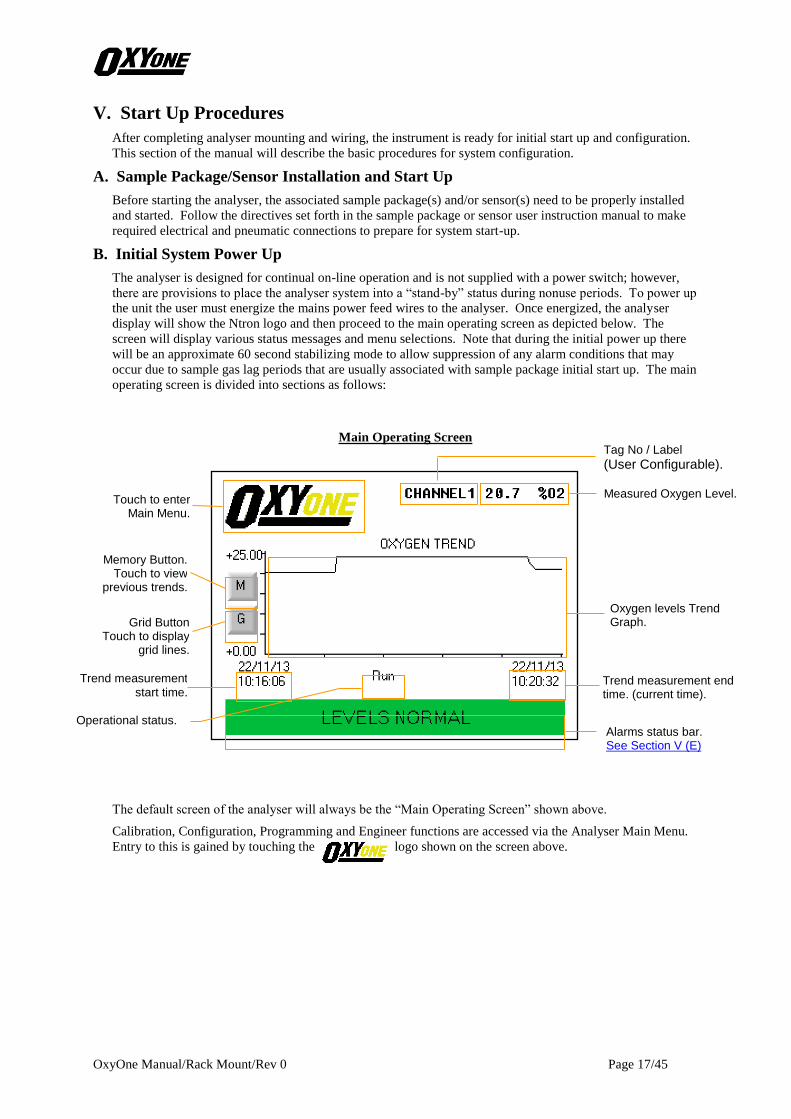
B. Initial System Power Up
The analyser is designed for continual on-line operation and is not supplied with a power switch; however,
there are provisions to place the analyser system into a “stand-by” status during nonuse periods. To power up
the unit the user must energize the mains power feed wires to the analyser. Once energized, the analyser
display will show the Ntron logo and then proceed to the main operating screen as depicted below. The
screen will display various status messages and menu selections. Note that during the initial power up there
will be an approximate 60 second stabilizing mode to allow suppression of any alarm conditions that may
occur due to sample gas lag periods that are usually associated with sample package initial start up. The main
operating screen is divided into sections as follows:
Main Operating Screen
The default screen of the analyser will always be the “Main Operating Screen” shown above.
Calibration, Configuration, Programming and Engineer functions are accessed via the Analyser Main Menu.
Entry to this is gained by touching the logo shown on the screen above.
Alarms status bar. See Section V (E)
Memory Button. Touch to view
previous trends.
Grid Button Touch to display
grid lines.
Trend measurement
start time.
Measured Oxygen Level.
Oxygen levels Trend Graph.
Trend measurement end time. (current time).
Touch to enter Main Menu.
Operational status.
Tag No / Label
(User Configurable).
OxyOne Manual/Rack Mount/Rev 0 Page 18/45
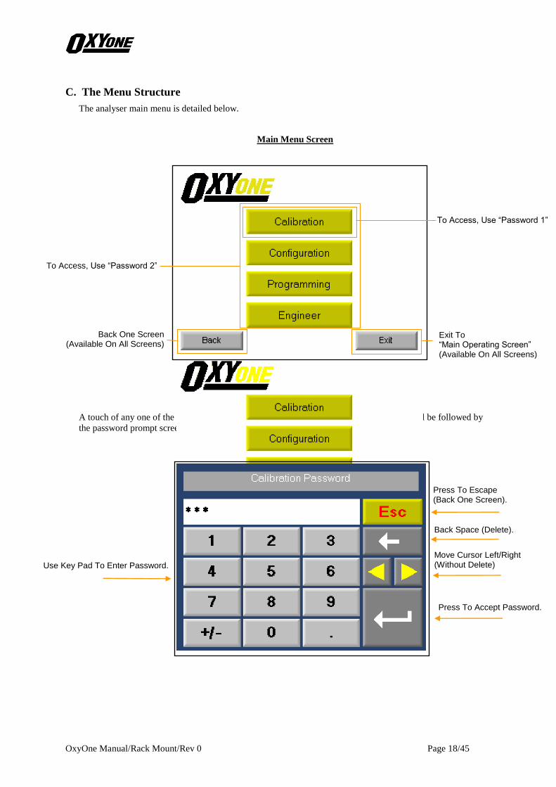
C. The Menu Structure
The analyser main menu is detailed below.
Main Menu Screen
A touch of any one of the Calibration, Configuration, Programming or Engineer buttons will be followed by
the password prompt screen below.
Exit To “Main Operating Screen” (Available On All Screens)
Back One Screen (Available On All Screens)
To Access, Use “Password 1”
To Access, Use “Password 2”
Use Key Pad To Enter Password.
Press To Accept Password.
Press To Escape (Back One Screen).
Back Space (Delete).
Move Cursor Left/Right (Without Delete)
OxyOne Manual/Rack Mount/Rev 0 Page 19/45
Password Security: The analyser is supplied with a password security feature so that until a password is
entered the user cannot proceed beyond the above “Main Operating Screen”. The first level, or Password 1,
will permit entry to the Calibration menu only. The second level, or Password 2, will permit entry into
Calibration, System Configuration and the Program System menus. The Engineer menu is reserved for
Ntron/Factory use only.
Default (Factory) Password 1 = 111
Default (Factory) Password 2 = 222
So as to maintain security and prevent accidental or intended interference it is recommended that the above
default values are reset. See section G, Paragraph 2
Note: Should the password be lost or forgotten, contact Ntron.
Note: The analyser functions are suspended during access to any of the menu screens.
Note: If any screen/menu other than the “Main Operating Screen” is selected, the analyser will
automatically revert back to the “Main Operating Screen” and resume all analyser functions
if no user input is received within a 90 second window.

OxyOne Manual/Rack Mount/Rev 0 Page 20/45
D. Main Menu Sub-Division & Password Steps.
The main menu subdivision and password steps are detailed below.
Section V(E) Section V(F) Section V(G)
By touching the Calibration, Configuration or Programming buttons on the Menu screen shown above, access
is gained to that sub-menu. The Engineer sub-menu is reserved for Ntron use only.
After touching the desired button, a password entry screen will load, requiring the operator to enter the
correct password for that sub-menu before access is allowed.
Note: Touching the Back button in any menu, reverts to the previous screen. Touching the Exit button in any
menu reverts to the “Main Operating Screen”.
OxyOne Manual/Rack Mount/Rev 0 Page 21/45
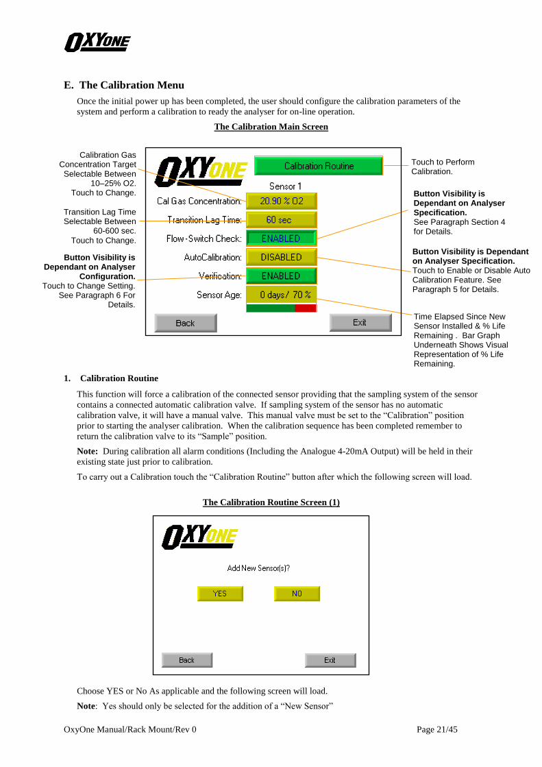
E. The Calibration Menu
Once the initial power up has been completed, the user should configure the calibration parameters of the
system and perform a calibration to ready the analyser for on-line operation.
The Calibration Main Screen
1. Calibration Routine
This function will force a calibration of the connected sensor providing that the sampling system of the sensor
contains a connected automatic calibration valve. If sampling system of the sensor has no automatic
calibration valve, it will have a manual valve. This manual valve must be set to the “Calibration” position
prior to starting the analyser calibration. When the calibration sequence has been completed remember to
return the calibration valve to its “Sample” position.
Note: During calibration all alarm conditions (Including the Analogue 4-20mA Output) will be held in their
existing state just prior to calibration.
To carry out a Calibration touch the “Calibration Routine” button after which the following screen will load.
The Calibration Routine Screen (1)
Choose YES or No As applicable and the following screen will load.
Note: Yes should only be selected for the addition of a “New Sensor”
Button Visibility is Dependant on Analyser Specification. Touch to Enable or Disable Auto Calibration Feature. See Paragraph 5 for Details.
Calibration Gas Concentration Target Selectable Between
10–25% O2. Touch to Change.
Transition Lag Time Selectable Between
60-600 sec.
Touch to Change.
Button Visibility is Dependant on Analyser Specification. See Paragraph Section 4 for Details.
Touch to Perform Calibration.
Time Elapsed Since New Sensor Installed & % Life Remaining . Bar Graph Underneath Shows Visual Representation of % Life Remaining.
Button Visibility is Dependant on Analyser
Configuration. Touch to Change Setting.
See Paragraph 6 For Details.
OxyOne Manual/Rack Mount/Rev 0 Page 22/45
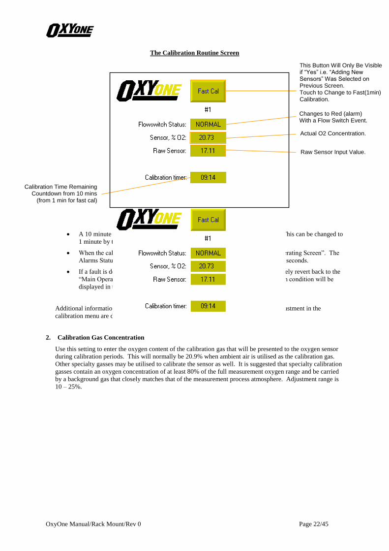
The Calibration Routine Screen
• A 10 minute calibration period is recommended when a new Sensor is fitted. This can be changed to
1 minute by touching the Fast Cal button.
• When the calibration is complete, the display will revert back to the “Main Operating Screen”. The
Alarms Status Bar on that screen will read ‘Stabilising’ for a approximately 30 seconds.
• If a fault is detected during the calibration sequence the analyser will immediately revert back to the
“Main Operating Screen”. When “Stabilising” is complete the associated alarm condition will be
displayed in the “Alarm Status Bar”
Additional information pertaining to the parameters and functions available for user adjustment in the
calibration menu are described below:
2. Calibration Gas Concentration
Use this setting to enter the oxygen content of the calibration gas that will be presented to the oxygen sensor
during calibration periods. This will normally be 20.9% when ambient air is utilised as the calibration gas.
Other specialty gasses may be utilised to calibrate the sensor as well. It is suggested that specialty calibration
gasses contain an oxygen concentration of at least 80% of the full measurement oxygen range and be carried
by a background gas that closely matches that of the measurement process atmosphere. Adjustment range is
10 – 25%.
Changes to Red (alarm) With a Flow Switch Event.
Actual O2 Concentration.
Raw Sensor Input Value.
This Button Will Only Be Visible if “Yes” i.e. “Adding New Sensors” Was Selected on Previous Screen. Touch to Change to Fast(1min) Calibration.
Calibration Time Remaining Countdown from 10 mins
(from 1 min for fast cal)
OxyOne Manual/Rack Mount/Rev 0 Page 23/45
3. Transition Lag Time
The transition lag time is an application specific parameter that is determined through sample system
configuration or sample line length. When the sample system switches from calibration to normal sample
gas modes nuisance alarms may occur due to false high oxygen levels. The false high oxygen levels may be
caused either by a short lived pressure spike incident upon the oxygen sensor during valve switch over; or,
high levels of oxygen may be resultant of long sample line purging periods required to flush the sample line
of calibration gas. To prevent the occurrence of such nuisance alarms a lag time can be programmed into the
analyser. The analyser will ignore all alarm conditions during the user defined transition lag time period.
The user must first determine what lag time period is required for the associated sampling system through
experimentation. Once the time period has been established, it can be programmed into the analyser in terms
of minutes. If the calibration solenoid valve is located within 0.5 meters (or 20 inches) of the sampler input
port, a one minute lag time should be adequate. Once the time period has been established, it can be
programmed into the analyser in terms of minutes.
4. Flow-Switch Check:
This option will only be visible if has been specified by the customer at the time of ordering.
Note: For for the flow-switch check to function the system must be fitted with an electro-pneumatic drive
gas isolation valve.
When specified, this option will force a check of the flowswitch condition as part of the calibration sequence.
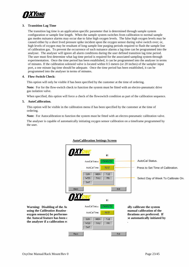
5. AutoCalibration.
This option will be visible in the calibration menu if has been specified by the customer at the time of
ordering.
Note: For Autocalibration to function the system must be fitted with an electro-pneumatic calibration valve.
The analyser is capable of automatically initiating oxygen sensor calibration on a timeframe programmed by
the user.
AutoCalibration Settings Screen
Warning: Disabling of the Autocal features REQUIRES the user to manually calibrate the system
using the Calibration Routine of the Calibration menu. It is suggested that manual calibration of the
oxygen sensor(s) be performed once per week; however, more frequent calibrations are preferred. If
the Autocal feature has been disabled a maintenance alarm condition will be automatically initiated by
the analyser if a calibration routine has not been run within seven (7) days.
AutoCal Status.
Press to Set Time of Calibration.
Select Day of Week To Calibrate On.

OxyOne Manual/Rack Mount/Rev 0 Page 24/45
6. Verification
This option will be visible if has been specified by the customer at the time of ordering.
Note: For Verification to function the system must be fitted with an electro-pneumatic Verification valve.
Verification allows the user to confirm the validity of the calibration measurement at a second point. This
will be checked every time a calibration is scheduled or demanded. Adjustment range is 0 – 25%.
Verification Settings Screen
Verification Gas Tolerance
Use this setting if the verification gas tolerance requires adjustment. Accuracy of the verification gas is
largely dependent upon sample lag time and gas mixing properties. Accuracy of 0.1% oxygen typically
demand 3 minute lag times (for an overall calibration cycle of 7.5 minutes). Accuracy of 0.3% oxygen
typically can be obtained in one minute. Adjustment range 0-25%.
Verification Status.
Press to Set Gas Concentration.
Touch to Select Allowable Gas Tolerance.

OxyOne Manual/Rack Mount/Rev 0 Page 25/45
F. The Configuration Menu
Once the system calibration has been configured the user should configure the system for on-line operation.
The parameters and functions available for user adjustment in the configuration menu are described on the
following pages:
The Configuration Main Screen
1. Adjust Oxygen Action Levels
The configuration of eight possible alarm conditions, based upon sensor levels, is performed with this routine.
The routine will permit the adjustment of the on and off setpoints and the severity level of each alarm
condition. An alarm level can be selected to activate the Sensor Guard rapid cycle calibration. The routine
will permit the configuration of the on and off setpoints for the following eight alarm conditions: Level A,
Level B, Level C, Level D, Level E, Level F, Level G, Level H.
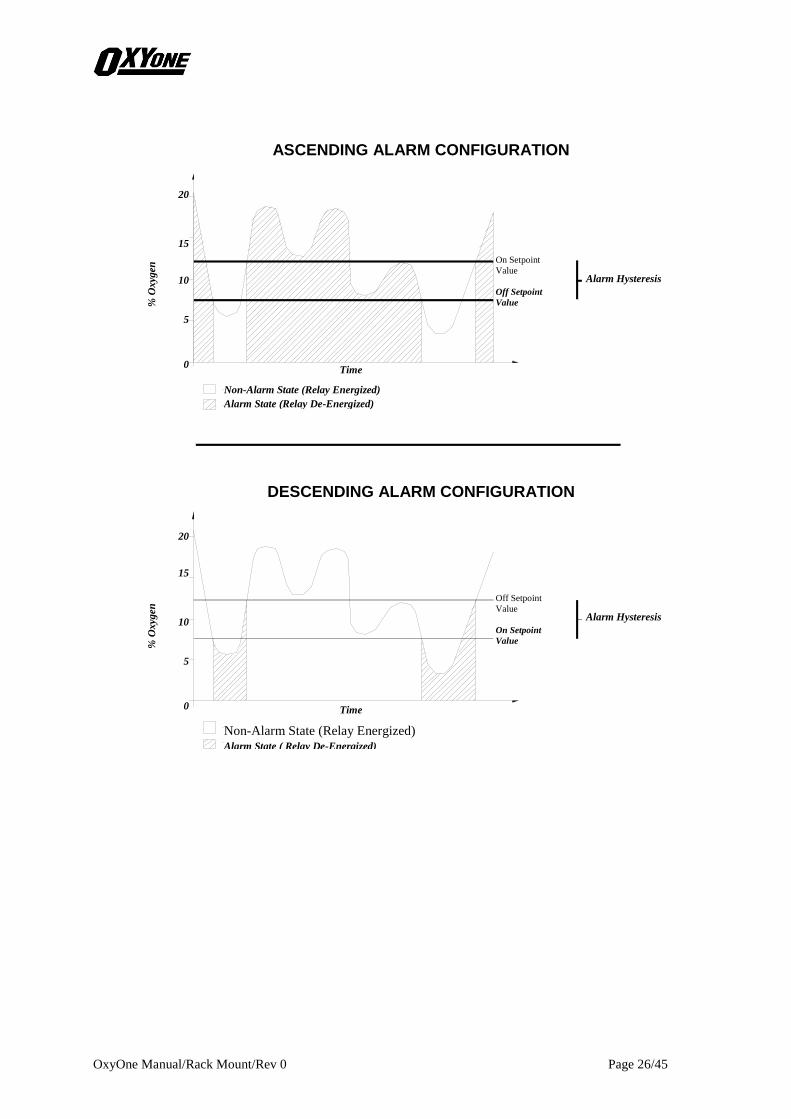
The on and off setpoints will determine alarm function as ascending or descending and establish the alarm
hysteresis. Ascending alarms are established by setting the on setpoint higher than the off setpoint.
Descending alarms are established by setting the off setpoint higher than the on setpoint. Alarm hysteresis is
established by the difference between the on and off setpoints. The on and off setpoints cannot be set to the
same value and must differ by at least 0.2% oxygen reading. Reference the diagram supplied below for
details of alarm functions.
Alarm severity can be set to NORMAL (Green), WARNING (Amber), ALARM (Red). When the
corresponding alarm event is reported on the alarm status bar it will have have the associated colour as its
background.
The user may have a level disabled. This is for unused or spare levels.
Sensor Guard, The Sensor Guard feature advances the calibration schedule to, typically, a two-hour
calibration frequency. This is for systems that monitor oxygen at very low levels and provides a confidence
check (via calibration) of the sensors condition.
View and Configure The Action Levels.
Touch to Enter Sub-Menu See Paragraph 1 for Details.
Sensor Simulator.
Touch to Enter Sub-Menu. See Paragraph 2 for Details.
Sensor Damping.
Touch to Change. See Paragraph 3 For details.
View and Set Date and Time.
Touch to Enter Sub-Menu. See Paragraph 5 For details.
Button Visibility Dependant on Analyser Specification. Touch to Enter Sub-Menu. See Paragraph 4 For Details.
Assign Channel Tag. Touch to Enter Keyboard Screen. See Paragraph 6 for Details. See
Analyser Serial Number.
OxyOne Manual/Rack Mount/Rev 0 Page 26/45
ASCENDING ALARM CONFIGURATION RESPONSE
% O
xygen
20
15
10
5
0
% O
xygen
20
15
10
5
0
DESCENDING ALARM CONFIGURATION RESPONSE
Non-Alarm State (Relay Energized)
Alarm State (Relay De-Energized)
On Setpoint
Value
Off Setpoint
Value
Alarm Hysteresis
Off Setpoint
Value
On Setpoint
Value
Alarm Hysteresis
Non-Alarm State (Relay Energized) Alarm State ( Relay De-Energized)
Time
Time

OxyOne Manual/Rack Mount/Rev 0 Page 27/45
Touch the Action levels button. The following screen will load.
The Action Levels Screen
Touch any of the Level buttons (A-H) to enter into a sub-menu for that action level. The following screen will
load. (Action Level ‘A’ shown as an example)
Action Level Sub-Menu Screen
Action level ‘A’ screen shown as an example.
Touch the back button to return to the Action Levels screen or the Exit button to return to the “Main
Operating Screen”.
Enable or Disable This Action Level. Touch to Change.
Set ‘ON’ Level. Touch to Enter Keyboard Screen. See Section 1 For Details.
Set ‘OFF’ Level. Touch to enter Keyboard screen. See Section 1 For Details.
Touch to Change Options Are,
Normal, Warning or Alarm.
Target Action Level.
Alarm Action Up Arrow –Rising Down Arrow - Falling
Sensor Guard Option Touch to Enable or Disable.

OxyOne Manual/Rack Mount/Rev 0 Page 28/45
2. Simulation
“What-If” scenarios can be manually entered in this mode to verify analyser function and response to specific
oxygen concentrations. The keypad will be utilized to manually enter a desired test oxygen level and will
replace the measured oxygen levels from the oxygen sensor for test purposes. During this mode the relay
contacts and 4-20mA current loop outputs perform exactly as if the oxygen sensor was providing the
concentration and the analyser was in its normal operational mode.
Simulation Screen
3. Damping
This function allows the user to reduce the effects of pressure pulses at the oxygen sensor. A pressure pulse
will cause a pulse change in the sensor output, that returns to the original output, in under 5 seconds. In
some applications this can trigger false alarms. The damping factor may be increased to minimize this
effect. The damping factor has four settings: Off (factory setting), Low, Medium, High.
4. Adjust Blow Back Control
This option will only be visible if has been specified by the customer at the time of ordering.
Note: For the blowback to function the system must be fitted with a blowback filter and associated electro-
pneumatic blowback valve.
This feature allows the OxyOne to periodically clean the sampling inlet by back-flushing the blowback filter
with a blast of inert gas.
Blowback Screen
Press to Enable/Disable.
Enter Desired O2 Concentration.
Equivalent 4-20mA Analogue Output.
Blowback Status.
Touch To Set Blowback Active/On Time.
Touch To Set Blowback Period/Off.

OxyOne Manual/Rack Mount/Rev 0 Page 29/45
5. Set Date/Time
This screen allows the setting of the Time, Date & Day.
Time & Date Screen
6. Assign Name Tags to Channel
Up to 10 character names can be assigned to the channel to assist the user in channel identification. The
setting entered on this screen will be displayed to the left of the Oxygen Reading in the top right hand corner
of the “ Main Operating Screen”, see Section V.
Time & Date Setting Screen
Touch To Change
Touch To Change.
Touch To Change.

OxyOne Manual/Rack Mount/Rev 0 Page 30/45
G. The Programming Menu
The parameters and functions available for user adjustment in the Programming menu are described on the
following pages.
The Programming Main Screen
1. Program Relays 1-8
The OxyOne is supplied with eight single pole, double throw relay contact sets (Identified as Relay’s 1-8).
The user may configure any of the 8 relays to correspond to a given condition (such as No Flow, or an Action
Level). This may be in any order. Furthermore, an output may be configured so that it is triggered by a
combination of conditions (e.g. if No Flow or System Fail happen, then assert output R1). The OxyOne is
designed to be adaptable to the needs of the user.
The possible outputs: Relay 1-8
The list of possible conditions is as follows:
1 – Action Level A 2 – Action Level B 3 – Action Level C 4 – Action Level D
5 – Action Level E 6 – Action Level F 7 – Action Level G 8 – Action Level H
9 – Sensor Difference 10 – No Flow, #1 11 – No Flow, #2 12 – Maintenance Required
13 – System Fault, #1 14 – System Fault, #2 15 – Calibrate, #1 16 – Calibrate, #2
17 – Drive Gas, #1 18 – Drive Gas, #2 19 – Blowback #1 20 – Blowback #2
21 – Verification #1 22 – Verification #2
Action Levels are the Ascending or Descending alarm points which the factory or the user has set
previously. The Maintenance Required Contact is asserted if the system experiences a problem that requires
attention, but is not interfering with accurate Oxygen measurement (for example, one sensor in a redundant
configuration gets wet and the other sensor is still good). System Fault is asserted for a given channel if it
experiences a problem which is unique to it. If channel number 2, for example, experiences a No Flow
condition, the System Fault, Chan 2 output will be asserted. The calibrate outputs signal the control valves to
divert cal gas to the sensors instead of sample gas. The optional drive gas outputs shut off sample flow
during standby and test sample flow switches during calibration, if the Drive outputs are connected. The
Blowback Filter output allows the OxyOne to periodically activate a solenoid valve to clean the filter
element with a blast of inert gas.
Assign Relay functions. Touch to Enter Sub-Menu.
See Paragraph 1 For Details.
Set Menu Passwords. Touch to Enter Sub-Menu. See Paragraph 2 For Details.
Calibration Due. Touch to Enter Sub-Menu.
See Paragraph 3 For Details.

OxyOne Manual/Rack Mount/Rev 0 Page 31/45
To program a relay touch the “Program Relay 1-8” button, the following screen will load.
The Program Relays 1-8 Screen
Touch any of the Level buttons (1-8) to enter into a sub-menu for that Relay. The following screen will load.
(Relay 1 shown as an example below).
Relay Sub-Menu Screen
Touch the back button to return to the Program Relays screen or the Exit button to return to the Main
Operating Screen.
Enable or Disable Relay. Touch to Change.
Assign Condition to Each Event Associated With the Relay. Touch to Change. See Paragraph 1 For
Details.
Target Relay

OxyOne Manual/Rack Mount/Rev 0 Page 32/45
2. Passwords
The analyser is supplied with a password security feature so that until a password is entered the user cannot
proceed beyond the above “Main Operating Screen”. The first level, or Password 1, will permit entry to the
Calibration menu only. The second level, or Password 2, will permit entry into Calibration, System
Configuration and the Program System menus. The Engineer menu is reserved for Ntron/Factory use only.
Default (Factory) Password 1 = 111
Default (Factory) Password 2 = 222
So as to maintain security and prevent accidental or intended interference it is recommended that the above
default values are reset. A touch of the “Passwords” button will load the following screen.
Password Editing Screen
Note: Should the password be lost or forgotten, contact Ntron.
Touch Button To Change.
Touch Button To Change.

OxyOne Manual/Rack Mount/Rev 0 Page 33/45
3. Calibration Due
Regular calibration of the oxygen sensor is essential for system reliability. This requirement will normally be
addressed by the analyser’s automatic calibration control. However for an analyser that has been configured
for manual calibration, this requirement can be easily overlooked. For this situation a programmable time
based reminder is provided. At the end of the programmed time a reminder Calibration Due message will
appear on the analysers “Alarm Status Bar”.
The Calibration Due Setting Screen
Touch Button To Enable/Disable
Touch To Set Cal Message Time Interval

OxyOne Manual/Rack Mount/Rev 0 Page 34/45

OxyOne Manual/Rack Mount/Rev 0 Page 35/45
VI. Operational Guidelines
A. Normal Operation
The OxyOne Analyser is designed for stand-alone operation. The user does not need to keep a watch on the
system or monitor its performance if not desired. Conditions of alarm that may impede analyser operation or
signal oxygen concentration alarms will be detected by the analyser and relayed to the user through the alarm
relay contact sets, 4-20mA current loop outputs, intrinsically safe solenoid valve outputs and display screen.
B. Calibration Modes
Calibration modes of the analyser will occur once every period as set by the user in Calibration main screen,
section V(E). Note that the calibration mode may only function automatically if the system has been
supplied & configured to do so i.e. the system has an electro-pneumatic calibration valve. In cases where
automatic calibration is not utilised, the user will be required to manually switch sample gas flow to the
calibration gas source before manually forcing calibration from the analyser’s “Calibrate Main Screen”.
Typical calibration periods will require approximately two minutes to complete once initiated. For systems
without auto-calibration valves, the user is advised to initially calibrate the sensor at least once a week until a
schedule of calibration can be determined based upon actual needs of the application. Automatic calibration
will remove the need of the user to perform weekly forced calibrations or determine the calibration needs of
the application. Note the use of the automatic calibration feature will provide the user with the greatest
measure of protection against sensor expiration and will provide the highest degree of sensor accuracy,
and will provide advance warning of sensor expiration.
C. 4-20mA Output Current Loop Signals
The analyser is supplied with a 4-20mA output current loop signal that is isolated and independent. The
range of the 4-20mA signal will correspond to an oxygen concentration level of 0% oxygen to a standard
upper level of 25% oxygen. The upper level can be changed to custom values, contact Ntron for assistance
should this be a requirement.
The 4-20mA current loop is capable of supporting an external load of 500 ohms. Loads in excess of this
specification will require the use of an external booster or current loop repeater. Contact Ntron for assistance
in selecting such a device if needed.
D. Alarm Relay Contact Sets
Relay contact sets are supplied as single-pole, double-throw connections on the individual relays. The relays
are designed to operate in a “fail-safe” condition meaning that all relays will be de-energised in the alarm
state. In the event of mains power failure or power supply module failure, all relays will revert to the de-
energized or alarm state. The relays are rated for 5 Amps @ 240 VAC or 5 Amps @ 30 VDC.
E. Analyser Messages
In addition to the alarm conditions reported by the relay contact sets, the analyser has several other conditions
that will also be reported on the main operating screen “Alarm Status Bar” (section V,B). The “Status Bar”
will scroll through the different alarms present at any given time. The background colour of the Status Bar
gives an indication of the alarm severity i.e. NORMAL (Green), WARNING (Amber), ALARM (Red). For
set point alarm messages, the colour of the background is programmable (section V,F,1). For all other alarm
messages the colour is hard programmed. Details as follows,
1. Levels Normal
No alarm events are present.
LEVELS NORMAL Alarm Status Bar

OxyOne Manual/Rack Mount/Rev 0 Page 36/45
2. No Flow
The sample conditioner flowswitch has detected no flow of sample gas. The alarm is hard programmed to the
system “Fault” output.
3. Calibration Due
This is a programmable time (elapsed time) based alarm (section G,3) reminding the customer to calibrate the
oxygen sensor. The alarm is hard programmed to the system “Maintenance Required” output.
4. Level Alarms
The available level alarms are “Level A to Level H” (section V,F,1). Each level alarm background colour can
be programmed to be any one of Green (normal), Amber (Warning), Red (Alarm). Example of “Level A” in
the different colours, as shown below.
5. Stabilising
This condition will be reported on the status bar during every system start up, sensor calibration and return to
normal sensor operation. The condition is the result of the analyser waiting for oxygen concentration signals
to stabilize as sample gas flows through the sample line plumbing to the sensor. This feature will avoid
nuisance alarms that would normally occur during sensor stabilisation.
LEVEL A NORMAL Alarm Status Bar
LEVEL A WARNING Alarm Status Bar
LEVEL A ALARM Alarm Status Bar
STABILISING Alarm Status Bar
#1 NO FLOW Alarm Status Bar
#1 CALIBRATION DUE Alarm Status Bar

OxyOne Manual/Rack Mount/Rev 0 Page 37/45
6. Cal Fail #1
If during a calibration sensor #1 is unable to calibrate correctly this alarm condition will be reported. The
alarm is hard programmed to the system “Fault” output. This condition has 6 variants as below.
The analyser has failed the calibration because the sample conditioner flowswitch detected no flow of
calibration gas during the calibration routine.
The analyser has failed the calibration because the sample conditioner flowswitch detected no flow of
calibration gas during the “Flow-Switch Check” step of the calibration routine.
Note: This alarm is related to the “Flow-Switch Check” function and will only be presented if the analyser
has been configured for it.
The analyser has failed the calibration because the sensor output is out of tolerance.
The analyser has failed the calibration because the sample conditioner flowswitch detected no flow of
verification gas during the “Verification” step in the calibration sequence.
Note: This alarm is related to the “Verification” function and will only be presented if the analyser has been
configured for it.
The analyser has failed the verification step in the calibration sequence. This can be caused by a leak in the
system, incorrectly programmed verification gas level, or a transition lag time setting that is too short.
Note: This alarm is related to the “Verification” function and will only be presented if the analyser has been
configured for it.
The analyser has failed the “New Sensor Calibration” because the new sensor output is out of tolerance.
#1 CAL FAIL-FLOW(+) CAL Alarm Status Bar
#1 CAL FAIL-FLOW(-) FS CHECK Alarm Status Bar
CALIBRATION FAIL#1 – SENSOR BAD Alarm Status Bar
#1 CAL FAIL – FLOW (+) VERIF Alarm Status Bar
#1 CAL FAIL – VERIF vs CAL GAS DIFF Alarm Status Bar
#1 CAL FAIL – NEW SENSOR BAD Alarm Status Bar
OxyOne Manual/Rack Mount/Rev 0 Page 38/45
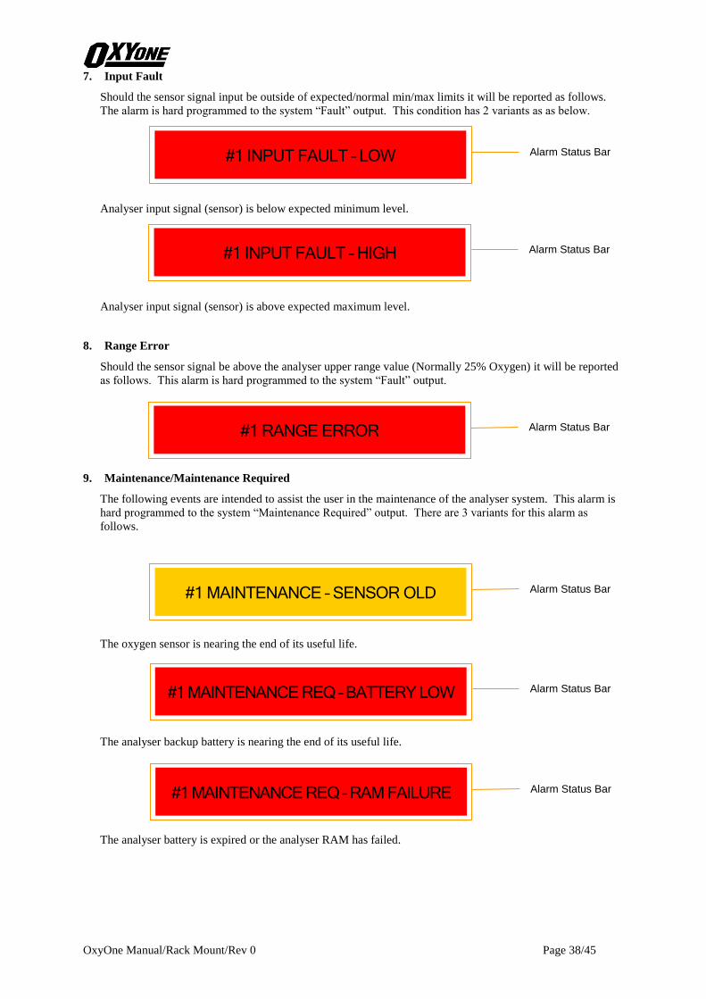
7. Input Fault
Should the sensor signal input be outside of expected/normal min/max limits it will be reported as follows.
The alarm is hard programmed to the system “Fault” output. This condition has 2 variants as as below.
Analyser input signal (sensor) is below expected minimum level.
Analyser input signal (sensor) is above expected maximum level.
8. Range Error
Should the sensor signal be above the analyser upper range value (Normally 25% Oxygen) it will be reported
as follows. This alarm is hard programmed to the system “Fault” output.
9. Maintenance/Maintenance Required
The following events are intended to assist the user in the maintenance of the analyser system. This alarm is
hard programmed to the system “Maintenance Required” output. There are 3 variants for this alarm as
follows.
The oxygen sensor is nearing the end of its useful life.
The analyser backup battery is nearing the end of its useful life.
The analyser battery is expired or the analyser RAM has failed.
#1 INPUT FAULT – LOW Alarm Status Bar
#1 INPUT FAULT – HIGH Alarm Status Bar
#1 RANGE ERROR Alarm Status Bar
#1 MAINTENANCE REQ – BATTERY LOW Alarm Status Bar
#1 MAINTENANCE – SENSOR OLD Alarm Status Bar
#1 MAINTENANCE REQ – RAM FAILURE Alarm Status Bar

OxyOne Manual/Rack Mount/Rev 0 Page 39/45
10. Blowback
When a the “Blowback” routine is active the following message is displayed.
#1 BLOWBACK IN PROGRESS Alarm Status Bar

OxyOne Manual/Rack Mount/Rev 0 Page 40/45

OxyOne Manual/Rack Mount/Rev 0 Page 41/45
VII. Maintenance Procedures
In the event that the analyser does not function properly or displays an error message or alarm, the user is to
refer to this section of the manual for troubleshooting, maintenance procedures and instructions for factory
assistance.
A. Factory Assistance or Analyser Return for Factory Service
In the event the user cannot determine and/or correct a problem encountered with the analyser, the factory
may be contacted for direct assistance. Contact the factory at the location listed below. Have the model
number, serial number, and this manual ready when calling to assist the technician in diagnosing and
correcting the problem.
Ntron Ltd.
Mullaghboy Industrial Park
Navan, Co. Meath, Ireland
Phone: ++353-46-9071333
FAX: ++353-46-9071331
E-Mail: [email protected]
Should the analyser require return to the factory for repair, contact the factory to receive a Return Material
Authorization Code (RMA). The code will aid the Service Department in expediting the repair. When
returning the analyser record the RMA, customer name and return address on the outside of the shipping box
and include a description of the problem.
B. Troubleshooting Guidelines
The OxyOne is designed for stand-alone, trouble free operation. In the event of error messages or problems
encountered during analyzer utilisation, the user is supplied the following guidelines to assist in analyser
troubleshooting. Difficulties in diagnosing and solving encountered problems should be reported to Ntron.
1. Wiring Faults.
The majority of problems encountered in the field are usually the result of wiring errors or open wire circuits.
Whenever a problem is encountered with devices, alarms or signals directly connected to the analyser first
inspect all wiring connections to verify correct installation. All wiring connections should be made as
directed by this manual or by custom documentation supplied with the analyser. Use the Simulation feature
to manually enter oxygen levels and test the response of the analyser and all connected devices.
2. Sensor Old, Sensor Bad Message.
The Old message will appear whenever the sensor nears the end of its expected life; or, whenever the sensor
outputs have dropped below acceptable levels during calibration as determined by the analyser. If the
analyser is not configured for automatic calibration, a manual calibration should be employed on a regular
(daily) basis to verify sensor performance. Replacing & calibrating the new sensor can clear the alarm.
The Bad message will appear whenever sensor #1 is at the end of its its expected life; or, whenever the sensor
outputs have dropped below acceptable levels during calibration as determined by the analyser. Replacing &
calibrating the new sensor can clear the alarm.
3. Flow Related Fault Messages.
This message will occur whenever the flow switch of the connected sampling system does not indicate proper
flow during normal operation or calibration modes. Loss of flow to the sensor can be caused by a variety of
issues such as clogged sample lines, clogged sample filters, loss of sample package motive force or closed
valves. Refer to the Sample Package User Instruction Manual for greater detail in diagnosing and
correcting flow problems. The message will specify to the user if the flow condition has occurred on during
normal sampling or during calibration periods.
OxyOne Manual/Rack Mount/Rev 0 Page 42/45
4. System Maintenance Alarm Relay Contact.
The System Maintenance relay will be placed into the alarm state whenever the analyser detects a situation
that may hamper proper operation or function. Refer to the Alarm Status Bar of the Main Operating Screen
for the specific annunciated events and to the issues above for their correction.
5. System Fault Alarm Relay Contact.
The System Fault relay will be placed into the alarm state whenever the analyser detects a situation that may
indicate an internal analyser failure, a loss of flow to the oxygen sensor or a sensor calibration error. Refer to
Alarm Status Bar of the Main Operating Screen for an explanation of the cause and to the issues above for
their correction.
6. One Relay Contact Constantly in Alarm State.
If the relay is constantly in its alarm state and has no attendant Alarm Status Bar message replace the realy
as necessary.
7. Sensor Guard.
The Sensor Guard feature advances the calibration schedule to, typically, a two-hour calibration frequency.
This is for systems that monitor oxygen at very low levels and provides a confidence check (via calibration)
of the sensors condition. Alternatively this feature allows the analyser to detect a sensor that may have be
exposed to excessive levels of solvent vapour, by increasing the calibration frequency. The act of calibration
can help dry out the sensor and thereby increase its service life.
8. 4-20mA Current Output is in its Fault State.
In its fault state the analyser current output will will be held at 20mA. This is activated if the system detects
any fault related condition, i.e. an oxygen sensor is bad, a low flow condition during calibration and or
normal operation etc. A message on the Alarm Status Bar will describe the related problem.
C. Spare Parts Listing
The below listed spare parts are available through the local Ntron distributor or representative or directly
from the Ntron.
User Instruction Manual Contact Ntron
I.S. Barrier Interface Contact Ntron
Analyser Module: 02-311
Analyser I/O Module: 02-312
Power Supply Module: 02-895
Relay Interface: Contact Ntron
Note: Analyser modules, power supply modules and user instruction manuals are available in languages
other than English.

OxyOne Manual/Rack Mount/Rev 0 Page 43/45
VIII. Specification Listing
A. System Specifications
1. Oxygen Measurement
Range: 0-25% Oxygen by volume
Resolution: 0.01% Oxygen from 0 – 10%, 0.1% Oxygen from 10 – 25%
Accuracy: Instrument: 0.03% absolute before fuel cell linearization
Accuracy with Fuel Cell Linearization: 0.05% absolute
Accuracy: Hysteresis and Repeatability: 0.05% absolute
Sensor-Type: Sealed, disposable, electrochemical fuel cell
Sensor-Range: 0-25% Oxygen, by volume
Sensor-Typical Life: 9-12 months, warranted 6 months
Sensor-Calibration Gas: Ambient Air (20.9% Oxygen)
2. Instrument
Display: 5.7” (QVGA) TFT LCD, White LED Backlight, Resistive Touchscreen.
mA Current Loop Output: Isolated 4-20mA with configurable range, Maximum Load = 500 ohms, Non-
Linearity less than 0.04mA
Relay Alarm Contacts-Rating: 5A @ 240VAC, 5A @ 30VDC, Single Pole, Double Throw
Relay Alarm Contacts-Action: Fail Safe (de-energized in alarm condition)
Relay Alarm Contacts-Supplied: 8 User Configured
Digital Inputs: 3 x PNP Source.
3. Miscellaneous
Operating Temperature Range: 0-50oC
Dimensions: 19.00” Wide x 4U High x 350mm Deep
Weight: 5.5 kg
Power Requirements: 85-260 VAC / 47-63 Hz
Power Consumption (Maximum): 0.56 Amps @ 115 VAC or 0.33Amps @ 230 VAC

OxyOne Manual/Rack Mount/Rev 0 Page 44/45

OxyOne Manual/Rack Mount/Rev 0 Page 45/45
IX. Warranty Statement
Ntron warrants, subject to the terms below, that the goods will be free from defects in design, materials and
workmanship for a period of (1) year from the date that the goods are shipped to the buyer.
THE SOLE LIABILITY OF NTRON FOR ALL PURPOSES SHALL BE TO REPAIR OR REPLACE, AT THE
SOLE OPTION OF NTRON, DEFECTS APPEARING WITHIN THE ONE YEAR PERIOD. NTRON SHALL
HAVE NO OBLIGATION FOR REPAIR OR REPLACEMENT UNLESS NTRON HAS RECEIVED
WRITTEN NOTICE OF THE ALLEGED DEFECT WITHIN THE ONE YEAR PERIOD AND THE
DEFECTIVE GOODS ARE PROMPTLY RETURNED BY BUYER, AT THEIR EXPENSE. IF THE DEFECT
OCCURS UNDER CIRCUMSTANCES OF PROPER USE IN ACCORDANCE WITH ALL INSTRUCTIONS
AND MANUALS PROVIDED TO THE BUYER. NTRON WILL DELIVER THE REPAIRED OR NEW
GOODS TO BUYER AT NTRON'S EXPENSE. IN NO EVENT WILL NTRON BE LIABLE FOR ANY LOSS
OR DAMAGE DIRECTLY OR INDIRECTLY ARISING FROM THE DEFECTS OR FROM THE USE OF
THE GOODS OR FOR CONSEQUENTIAL OR INCIDENTAL DAMAGES, WHETHER IN CONTRACT,
TORT OR OTHERWISE, FOR PERSONAL INJURY OR PROPERTY DAMAGE OR ANY FINANCIAL
LOSS.
The buyer shall be responsible for insuring that the goods are functioning properly at all times and shall not use
any goods which are not functioning properly. Buyer, therefore, agrees to indemnify Ntron from and against all
losses and claims to or by any person or property caused in any manner by the goods or the use of the goods,
including any expenses and attorney's fees in connection with all claims, demands, proceedings, or other
expenses. Any description of the goods contained in any documents to which these warranty provisions relate,
including any quotations or purchase orders relating to the goods being delivered to buyer, are for the sole
purpose of identifying the goods, and any such description, as well as any sample or model which may have been
displayed to or seen by buyer at any time, have not been made part of the basis of the bargain and have not
created or amounted to any express warranty that the goods would conform to any such description or any such
sample or model. Notwithstanding any other terms of these warranty provisions, all oxygen sensors sold by
Ntron shall be warranted against defects in design, materials or workmanship only for a period of six (6) months
from date of shipment. If the sensor under normal operation fails within such six (6) month period, it must be
returned to Ntron at the address set forth above, at the buyer's expense, and Ntron will promptly ship to buyer at
the expense of Ntron, a replacement sensor.
NTRON DOES NOT WARRANT THAT THE GOODS ARE FREE OF THE RIGHTFUL CLAIM OF ANY
THIRD PERSON BY WAY OF INFRINGEMENT OF PATENTS OR OTHER PROPRIETARY
INFORMATION AND DISCLAIMS ANY WARRANTY AGAINST SUCH INFRINGEMENT.
It shall be the responsibility of the buyer to read carefully and abide by all instructions provided to the buyer in
the instruction manual or elsewhere. If buyer, and the employees of the buyer did not abide by such instructions,
then the alleged defect shall not be deemed to have arisen under circumstances of proper use. The terms of these
warranty provisions shall apply to all products sold by Ntron. No waiver, alteration or modification of the terms
of these provisions shall be valid unless in writing and signed by an executive officer of Ntron.
EXCEPT AS SPECIFICALLY SET FORTH AND LIMITED IN THIS PARAGRAPH, NTRON MAKES NO
WARRANTIES, EXPRESS OR IMPLIED, INCLUDING WARRANTIES AS TO MERCHANTABILITY, OR
AS TO THE FITNESS OF THE GOODS OR ANY PARTICULAR USE OR PURPOSE, AND ANY
WARRANTIES SET FORTH IN THIS PARAGRAPH ARE IN LIEU OF SUCH IMPLIED WARRANTIES OF
MERCHANTABILITY AND FITNESS FOR PARTICULAR USE OR PURPOSE.


