
General Bid Bulletin No. 16
Annex “A”
Page 1 of 14
North – South Commuter Railway (NSCR) Project (Malolos – Tutuban)
Package CP02: Elevated Structures and 3 Stations
ITEM
NO.
REFERENCE
CLAUSE/
SECTION
CLARIFICATION REQUEST RESPONSE
Volume II, Part 2 – Work Requirements
TS 400
1 Page TS400-455,
Clause 555.1.3,
Specifications
(Signages)
Reference:
"Signs shall be designed in accordance with the relevant
and applicable sections of the BNBC:"
As specified in TS455, BNBC shall be used for the design
of the signages. We proposed to use the applicable
code/standard in the Philippines.
Yes, the Bidder’s proposal is acceptable.
TS 500
2 Pages TS500-212
and TS500-219,
Clause 522
Aluminum
Composite Material
522.1.4 (Product Composition and Material Properties)
indicates that skin material thickness is 0.5mm, while
522.3.2 (Material) indicates that thickness is 0.3mm. Please
confirm which clause no. will govern.
The skin material thickness for the Aluminum Composite Material
shall be 0.5mm thk. as indicated in TS 500, Clause 522.1.4.
3 Page TS500-212, 522
Aluminium
Composite Material
Reference:
Aluminium Composite Material Manufacturer
Maythe Employer accept torelaxthe Technical
Specificationfor Architecture TS500 requirements
allowingmanufacturer'sfrom other countries, other than
Japan, to reduce our BidCost?
The Bidder’s proposal is accepted provided that the total cost of
goods and services procured from Japan shall not be less than
thirteen percent (13%) of the Accepted Contract Amount,
including Provisional Sums in accordance with Section IV
Bidding Forms – Schedule 3: List of Japanese Origin, Goods &
Services and Section V Eligible Source Countries of Japanese
ODA Loans.
The Bidder shall ensure that the product must meet the general
standards as specified in the Technical Specifications including
Requirements for Testing of Materials.
4 Page TS500-249,
Clause 527, Metal
Louvers
TS 527.1(Page 249) describes that The Works shall consist
in accordance with this Specification and in conformity
with the Drawings or as established by the Engineer.
All louver profiles or types, as shown in the drawings in Book 2 of
3, Pages CP02-B2-095, CP02-B2-342 and CP02-B2-614, Drawing
Nos. NSCR-DWG-BAL-AR-3456, NSCR-DWG-GUI-AR-3456,

General Bid Bulletin No. 16
Annex “A”
Page 2 of 14
North – South Commuter Railway (NSCR) Project (Malolos – Tutuban)
Package CP02: Elevated Structures and 3 Stations
ITEM
NO.
REFERENCE
CLAUSE/
SECTION
CLARIFICATION REQUEST RESPONSE
May the Bidder understands that, as far as the Contractor
selects the Louver manufacturer, requirements in the
product function and the installation in accordance with all
technical description at TS527(page 249 to 259), the Bidder
can submit the Bid and the Contractor can propose the
Louver products for the Engineer's approval under the
condition that the Products are not necessarily identical in
the shape with that of the Tender Drawing "Package Cp02
Volume Ⅱ of Ⅴ, NSCR-DWG-BAL- AR-3456, NSCR-
DWG-GUI-AR-3456, NSCR-DWG-MAL- AR-3456".
The purpose of the above is to achieve the economical Bid
by searching the alternative Louver products with
equivalent function. Please kindly advise.
NSCR-DWG-MAL-AR-3456 Architectural – Louver Typical
Details, respectively, were selected and specified to meet the
general standards of the Technical Specifications and to provide
the best solutions to external forces. The Contractor shall submit
shop drawings to the Engineer for approval prior to the
commencement of works as per the required specifications to
ensure that the intent of the drawing is followed.
5 Page TS500-453,
Clause 554.4.2, Basis
of Payment
Please clarify if the following Stations Building Item
Number and Description is included in the contractor's
scope:
554(2) Furnishing (Entrance Floor Mats and Frames)
554(12) 4000x1000mm w/s, Cash Counter.
If included, please provide specifications.
Furnishing (Entrance Floor Mats & Frames) is included in the
CP02 Contractor’s Scope of Works as specified in TS 500, Clause
544.3.2.2.
Item 4000mm x 1000mm Cash Counter is within the CP04
Contractor’s Scope of Works.
6 Page TS500-455,
Clause 554.4.2, Basis
of Payment
Details for the following Stations Building Item Number
and Description: 554(23) 600x1200mm Center Tableis
different from the specification stated in the Furniture
Legend with drawing numbers NSCR-DWG-BAL-AR-
3341, NSCR-DWG-GUI-AR- 3331, NSCR-DWG-MAL-
AR-3331 which is 480mmx270mmx130mm H Center
Table. Please clarify which specifications are we going to
use.
Please follow 600mm x 1200mm size for the Center Table as
indicated in TS 500, Clause 554.4.2. This is applicable to all
Stations.
7 Page TS500-455 Please clarify if the following Stations Building Item All Stations Building Item Number and Descriptions referenced in

General Bid Bulletin No. 16
Annex “A”
Page 3 of 14
North – South Commuter Railway (NSCR) Project (Malolos – Tutuban)
Package CP02: Elevated Structures and 3 Stations
ITEM
NO.
REFERENCE
CLAUSE/
SECTION
CLARIFICATION REQUEST RESPONSE
Drawings, Book 2 of
3, Pages CP02-B2-
018; CP02-B2-255;
and CP02-B2-515,
Architectural
Concourse Level
Plan (All stations)
Number and Description is included in the contractor's
scope:
554(4) Point of Sale Machine
554(3) Ticket Vending Machine
Automatic Gates
If yes, please provide specifications and kindly clarify the
following:
1. No. of Gates Required
2. Type of Gate Configurations - Wide One Way/Wide
Bi-Directional/Emergency
Swing Gates(this normally would also be subjected to the
floor plan of the stations)
3. Type of Gates - Turnstile/Flap/Sliding Glass
4. Fare Media - QR Ticket/Contactless Card based
ticket/Other
5. Closed Loop or Open Loop System - Closed Loop as
per item 4, open loop system means acceptance of
VISA
Paywave/MastercardPaypass/UnionPayQuickPass etc.
6. What kind of fare policies - Rate of a ticket by
station/zone/distance, discounted or concesion tickets
for elderly, students, season pass, etc.
7. How many (per station);
a. Ticket Vending Machines
b. Ticket Office Machines
c. Excess Fare Office
d. Ticket Reader (if necessary)
8. What is the network infrastructure between stations? -
Fiber Optics/3G/4G etc.
9. Who will be operating the AFC System upon handling
the Clarification Request are within the CP04 Contractor’s Scope
of Works.

General Bid Bulletin No. 16
Annex “A”
Page 4 of 14
North – South Commuter Railway (NSCR) Project (Malolos – Tutuban)
Package CP02: Elevated Structures and 3 Stations
ITEM
NO.
REFERENCE
CLAUSE/
SECTION
CLARIFICATION REQUEST RESPONSE
over/completion?
10. Any project managers or director that will manage the
interaction with PNR or Authorities for civil works
and the necessary information from time to time?
11. Who will handle the Civil works in laying or running
cables like data/network cables, electrical cables from
the different point to the gates and the station control?
12. Who will be providing the financing of the project?
8 Page TS500-456,
Clause 555.1.6,
Billboard Signs
Please provide locations and drawings for Billboard Signs. For Billboard Signage details, please refer to Book 2 of 3, Page
CP02-B2-289, Drawing No. NSCR-DWG-GUI-AR-3254
Architectural Floor Mounted Billboard Signage Detail.
For Billboard Signage locations, please refer to Page CP02-B2-
285, Drawing No. NSCR-DWG-GUI-3241 Architectural
Concourse Level & Platform Level Signage Plan. This applies to
all Stations.
Drawings
Book 2 of 3
9 Page CP02-B2-015,
251, 511, Glass
WallThickness
Reference:
Glass Wall Thickness
Due to the availability of the Spider fittings for 16mm glass
thickness, may the Employer accept to reduce the
requirement of the thickness of the glass from 16:6:16 to
8:6:8 instead?
Please follow 16:6:16 glass thickness indicated in Pages CP02-
B2-015, CP02-B2-251 and CP02-B2-511, Drawing Nos. NSCR-
DWG-BAL-3007, NSCR-DWG-GUI-3007, NSCR-DWG-MAL-
3007 Architectural - Summary Specifications Sheet 2.
10 Pages CP02-B2-018;
CP02-B2-024; CP02-
B2-025, Balagtas
Station Architectural
- Architectural Plan
Concourse level
1. For W2 - 528(1) (NSCR-DWG-BAL-AR-3111) shown
in window tag plan at Grid 4-6 & Grid 13-14 has a
different quantity shown in Right Elevation Plan
(NSCR-DWG-BAL-AR-3132)
Please use the following:
1. Please follow Page CP02-B2-018, Drawing No. NSCR-
DWG-BAL-AR 3111 between Grid Lines 4-6 along Grid
Line A, it shall be read as W2=4sets.

General Bid Bulletin No. 16
Annex “A”
Page 5 of 14
North – South Commuter Railway (NSCR) Project (Malolos – Tutuban)
Package CP02: Elevated Structures and 3 Stations
ITEM
NO.
REFERENCE
CLAUSE/
SECTION
CLARIFICATION REQUEST RESPONSE
Concourse Level 2. For W2 - 528(1) shown in window tag plan (NSCR-
DWG-BAL-AR- 3111) at Grid 13-14 has a different
quantity shown in Left Elevation Plan (NSCR-DWG-
BAL-AR-3131)
3. For L2A - 527(4) shown in window tag plan (NSCR-
DWG-BAL-AR- 3111) at Grid 13-14 but is reflected as
L2C - 527(4) in Right & Left Elevation Plan (NSCR-
DWG-BAL-AR-3132)
4. For L2A & L2B - 527(4) shown in window tag plan
(NSCR-DWG-BAL- AR-3111) at Grid 14-15 but not
shown in Right Elevation Plan (NSCR- DWG-BAL-
AR-3132)
Please clarify which plan shall govern.
2. Please follow Page CP02-B2-018, Drawing No. NSCR-
DWG-BAL-AR 3111 between Grid Lines 13-14 along Grid
Line D, it shall be read as W2=2sets.
3. Follow Designation of L2A & L2C in Page CP02-B2-024,
Drawing No. NSCR-DWG-BAL-AR 3131 Elevations Sheet
1 and Page CP02-B2-025, Drawing No. NSCR-DWG-BAL-
AR 3132 Elevations Sheet 2.
4. In Page CP02-B2-018, Drawing No. NSCR-DWG-BAL-AR-
3111 Architectural Plan Concourse and Platform Level, use
L2A near Grid Lines A& 15 and use L2C near Grid Lines A
& 14. The rest between Grid Lines 14 and 15 along Grid Line
A, use L2B.
11 Page CP02-B2-018,
Balagtas Station
Architectural -
Architectural Plan
Concourse And
Platform Level
In the Schedule of Finishes (NSCR-DWG-BAL-AR-3201)
there is a Janitor Sink and Trash Room in the Back of the
House but it cannot be located in the floor plan (NSCR-
DWG-BAL-AR-3111). Please provide location of the
facilities.
The Janitor Sink is located along Grid 6 between Grids B & C
near GAD & BFR as shown in Page CP02-B2-018, Drawing No.
NSCR-DWG-BAL-AR-3111 Architectural Plan Concourse &
Platform Level.
The Trash Room is located along Grids 18 & D as shown in Book
2 of 3, Page CP02-B2-018, Drawing No. NSCR-DWG-BAL-AR-
3111 Architectural Plan Concourse & Platform Level.
12 Page CP02-B2-018,
Balagtas Station
Architectural -
Architectural Plan
Concourse and
Platform Level
Please provide details for Ramp 1 & 2 (Emergency Exit) For details of Ramp-1, please refer to Page CP02-B2-062 Ramp
Details. For details of Ramp-2 and other Ramps, the Contractor
shall submit shop drawings to Engineer for approval prior to start
of works.
13 Pages CP02-B2-027 Please provide the following information for Maintenance The maintenance catwalk mentionedin Volume IA, BOQ,

General Bid Bulletin No. 16
Annex “A”
Page 6 of 14
North – South Commuter Railway (NSCR) Project (Malolos – Tutuban)
Package CP02: Elevated Structures and 3 Stations
ITEM
NO.
REFERENCE
CLAUSE/
SECTION
CLARIFICATION REQUEST RESPONSE
to 028; CP02-B2-
264 to 265; CP02-
B2-524 to CP02-B2-
525, Reflected
Ceiling Plan and
Details (all stations)
Catwalk mentioned in BOQ no. 3, pages 37, 54 and 71,
item no. 411(2):
1. Please confirm if the maintenance catwalk is designed
for pedestrian loading only.
2. Structural steel support/bracing details
BOQNo.3 in Pages BOQ-37,BOQ-54andBOQ-
71,Itemno.411(2) is only for maintenance use of the staff. For
other details needed, the Contractor shall submit shop drawings to
the Engineer for approval prior to start of works.
14 Page CP02-B2-033,
Balagtas Station
Architectural -
Architectural Plan
Concourse And
Platform Level
Floor finish for Trash Room specified in floor pattern
layout (NSCR- DWG-BAL-AR-3181) is 900x900x12mm
thk. Non-skid granite, while in Schedule of Finishes
(NSCR-DWG-BAL-AR-3201) it is self levelling epoxy.
Please confirm which is correct.
Please follow PageCP02-B2-036, Drawing No. NSCR-DWG-
BAL-AR-3201 Schedule of Finishes that indicates Self
Levelling Epoxy Paint with Hardener. This applies to all
Stations.
15 Pages CP02-B2-036;
CP02-B2-271: CP02-
B2-534, Schedule of
Finishes and Toilet
Plans and Details
(All Stations)
According to Schedule of Finishes(NSCR-DWG-BAL-AR-
3201, NSCR-DWG-GUI-AR-3201, & NSCR-DWG-MAL-
AR-3201), thickness of ceramic wall tiles is 6mm, while
according to Toilet Plans and Details( NSCR-DWG-BAL-
AR-3271, NSCR-DWG-GUI-AR-3271, & NSCR-DWG-
GUI-AR-3271) thickness of ceramic while tiles is 9.5mm.
Please confirm which shall govern.
Please use 6 mm thk ceramic tiles for Walls of Toilets as indicated
in Pages CP02-B2-036, CP02-B2-274, CP02-B2-534, Drawing
Nos. NSCR-DWG-BAL-AR-3201, NSCR-DWG-GUI-AR-3201
NSCR-DWG-MAL-AR-3201 Schedule of Finishes. Please use 9
mm-10 mm thk ceramic tiles for Floors of Toilets for all the
Stations.
16 Pages CP02-B2-058
to CP02-B2-063;
CP02-B2-066 to
CP02-B2-067; CP02-
B2-300 to CP02-B2-
307; CP02-B2-310 to
CP02-B2-311; CP02-
B2-563 to CP02-B2-
569; CP02-B2-572 to
CP02-B2-573, Stair
and Ramp Details
Railing shown in stair details (NSCR-DWG-BAL-AR-
3291, NSCR-DWG-GUI-AR-3291 and NSCR-DWG-
MAL-AR-3291) did not match with the blow-up detail
specified (NSCR-DWG-BAL-AR-3316, NSCR-DWG-
GUI- AR-3316 and NSCR-DWG-MAL-AR-3316). Please
confirm which one to follow.
On Drawing Nos. NSCR-DWG-BAL-AR-3291, NSCR-DWG-
GUI-AR-3291, NSCR-DWG-MAL-AR-3291 (Pages CP02-
B2-058, CP02-B2-300 and CP02-B2-563) Architectural-Stair
Details Sheet 1 respectively, please follow Detail G for railings
at end without wall, Detail E for railings on concrete walls,
Detail E for intermediate railings, but with vertical members of
Drawing Nos. NSCR-DWG-BAL-AR-3316, NSCR-DWG-
GUI-AR-3316, NSCR-DWG-MAL-AR-3316 Architectural –
Railing Typical Details Sheet 1 (Pages CP02-B2-066, CP02-
B2-310 and CP02-B2-572).

General Bid Bulletin No. 16
Annex “A”
Page 7 of 14
North – South Commuter Railway (NSCR) Project (Malolos – Tutuban)
Package CP02: Elevated Structures and 3 Stations
ITEM
NO.
REFERENCE
CLAUSE/
SECTION
CLARIFICATION REQUEST RESPONSE
(All stations)
17 Pages CP02-B2-058
to CP02-B2-063;
CP02-B2-066 to
CP02-B2-067; CP02-
B2-300 to CP02-B2-
307; CP02-B2-310 to
CP02-B2-311; CP02-
B2-563 to CP02-B2-
569; CP02-B2-572 to
CP02-B2-574, Stair
and Ramp Details
(All stations)
Please identify the location of Stainless Steel Railing/Gate
(48.6Ø x 3.0 Hairline Finish including Accessories;
H=1100~1200mm) - 506(30) on plan.
Please refer to Pages CP02-B2-018, CP02-B2-255 and CP02-B2-
515, Drawing Nos. NSCR-DWG-BAL-3111, NSCR-DWG-GUI-
3111, NSCR-DWG-MAL-AR-3111 Architectural Plan Concourse
& Platform Levels for the location of:
a. Concourse Ticket Area Service Gate & Railing; and
b. Platform Safety Railing & Gate having dimensions of 48.6dia.
x 3.0 Hairline Finish including accessories; H=1100-
1200mm).
18 Page CP02-B2-071,
Balagtas Station -
Architectural
Concourse and
Platform Level
Furniture and
Equipment Layout
Plan and Details
We can't find highlighted furnitures on Concourse Level
grid 2 & 3 (NSCR-DWG-BAL-AR-3331) in the given
Furniture Legend (NSCR- DWG-BAL-AR-3341). Please
clarify if it is included in our scope. If yes, please provide
specifications.
Equipment inside the room/s in Concourse Level between Grids 2
and 3 as shown Page CP02-B2-071, Drawing No. NSCR-DWG-
BAL-3331 Architectural Concourse Level Furniture and
Equipment Layout Plan and Details are within the CP04 Scope of
Works.
19 Pages CP02-B2-071;
CP02-B2-315; CP02-
B2-577, Balagtas,
Guiguinto Station
and Malolos-
Architectural
Concourse Level
Furniture and
Equipment Layout
Please confirm if the following furniture are included in the
contractor's scope: Money Trolley, Cashbox,Sec. Bag &
Card Cassete, Bed and Safe & Card Locker (NSCR-
DWG-GUI-AR-3331,NSCR-DWG-BAL-AR-3341).
If included, please identify the locations of these furnitures.
The items shown and indicated in the drawing in Pages CP02-B2-
071, CP02-B2-072, CP02-B2-315 and CP02-B2-316, Drawing
Nos. NSCR-DWG-BAL-3331, NSCR-DWG-BAL-3341, NSCR-
DWG-GUI-AR-3331 and NSCR-DWG-GUI-AR 3341
respectively are within the Scope of Work of the CP04 Contractor.

General Bid Bulletin No. 16
Annex “A”
Page 8 of 14
North – South Commuter Railway (NSCR) Project (Malolos – Tutuban)
Package CP02: Elevated Structures and 3 Stations
ITEM
NO.
REFERENCE
CLAUSE/
SECTION
CLARIFICATION REQUEST RESPONSE
Plan and Details
20 Pages CP02-B2-071;
CP02-B2-577; CP02-
B2-315,
Architectural
Concourse Level
- Furniture Layout
Plan and Details (All
stations)
1) Please provide the location for Executive chair and
Visitor's chair indicated in Furniture Legend (NSCR-
DWG-BAL-AR-3341, NSCR-DWG- GUI-AR-3341
and NSCR-DWG-MAL-AR-3341).
2) A 700 x 1400mm Desk is shown in the following
Customer Service Room detail:
NSCR-DWG-BAL-AR-3321
NSCR-DWG-GUI-AR-3321
NSCR-DWG-MAL-AR-3321
However, it is not shown in the following Equipment
Layout Plan:
NSCR-DWG-BAL-AR-3331
NSCR-DWG-BAL-AR-3341
NSCR-DWG-GUI-AR-3331
NSCR-DWG-MAL-AR-3331
Please confirm which one to follow.
1. Please provide Executive Chair and Visitor’s Chair at the
Station Manager’s Room for each Station as indicated in the
Furniture Legend of Drawing Nos. NSCR-DWG-BAL-AR-
3341, NSCR-DWG-GUI-AR-3341 and NSCR-DWG-MAL-
AR-3341 Furniture Layout Plan & Details (Pages CP02-B2-
072,CP02-B2-316 andCP02-B2-578).
2. Please provide 700 x 1400mm Desk at the Customer Service
Room for each Station as shown in Drawing Nos. NSCR-
DWG-BAL-AR-3321, NSCR-DWG-GUI-AR-3321 and
NSCR-DWG-MAL-AR-3321 Customer Service Room
Details 1 (PagesCP02-B2-068, CP02-B2-312 andCP02-B2-
574).
21 Pages CP02-B2-090;
CP02-B2-337; CP02-
B2-609, Platform
Bench Typical
Details (all stations)
1. The size of the Platform Bench with the tag S1 has the
size of 450mm x 1200mm in the following Furniture
Details:
NSCR-DWG-BAL-AR-3341
NSCR-DWG-GUI-AR-3331
NSCR-DWG-MAL-AR-3331
However, the size specified is different in the following
Platform Bench Typical Details:
NSCR-DWG-BAL-AR-3446
NSCR-DWG-GUI-AR-3446
Please follow the size of the Platform Bench indicated in Drawing
No. NSCR-DWG-BAL-AR-3446 Platform Bench Typical Details
(Page CP02-B2-090). This applies to all Stations.
General Bid Bulletin No. 16
Annex “A”
Page 9 of 14
North – South Commuter Railway (NSCR) Project (Malolos – Tutuban)
Package CP02: Elevated Structures and 3 Stations
ITEM
NO.
REFERENCE
CLAUSE/
SECTION
CLARIFICATION REQUEST RESPONSE
NSCR-DWG-MAL-AR-3446
Please confirm which one to follow.
2. Please specify the location of supporter type bench
shown in Platform Bench Typical Details).
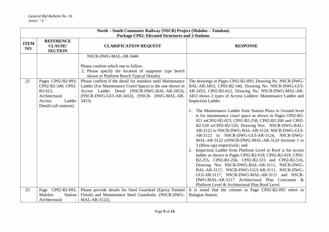
22 Pages CP02-B2-093;
CP02-B2-340; CP02-
B2-612,
Architectural -
Access Ladder
Details (all stations)
Please confirm if the detail for stainless steel Maintenance
Ladder (For Maintenance Crawl Space) is the one shown in
Access Ladder Detail (NSCR-DWG-BAL-AR-3453),
(NSCR-DWG-GUI-AR-3453), (NSCR- DWG-MAL-AR-
3453).
The drawings in Pages CP02-B2-093, Drawing No. NSCR-DWG-
BAL-AR-3453, CP02-B2-340, Drawing No. NSCR-DWG-GUI-
AR-3453, CP02-B2-612, Drawing No. NSCR-DWG-MAL-AR-
3453 shows 2 types of Access Ladders: Maintenance Ladder and
Inspection Ladder.
1. The Maintenance Ladder from Station Plaza to Ground level
is for maintenance crawl space as shown in Pages CP02-B2-
021 toCP02-B2-023, CP02-B2-258, CP02-B2-260 and CP02-
B2-518 toCP02-B2-520, Drawing Nos. NSCR-DWG-BAL-
AR-3122 to NSCR-DWG-BAL-AR-3124, NSCR-DWG-GUI-
AR-3122 to NSCR-DWG-GUI-AR-3124, NSCR-DWG-
MAL-AR-3122 toNSCR-DWG-MAL-AR-3124 Sections 1 to
3 (Blow-up) respectively; and
2. Inspection Ladder from Platform Level to Roof is for access
ladder as shown in Pages CP02-B2-018, CP02-B2-019, CP02-
B2-255, CP02-B2-256, CP02-B2-515 and CP02-B2-516,
Drawing Nos NSCR-DWG-BAL-AR-3111, NSCR-DWG-
BAL-AR-3117, NSCR-DWG-GUI-AR-3111, NSCR-DWG-
GUI-AR-3117, NSCR-DWG-MAL-AR-3111 and NSCR-
DWG-MAL-AR-3117 Architectural Plan Concourse &
Platform Level & Architectural Plan Roof Level.
23 Page CP02-B2-093,
Malolos Station
Architectural -
Please provide details for Steel Guardrail (Epoxy Painted
Finish) and Maintenance Steel Guardrails. (NSCR-DWG-
MAL-AR-3122).
It is noted that the column in Page CP02-B2-093 refers to
Balagtas Station.

General Bid Bulletin No. 16
Annex “A”
Page 10 of 14
North – South Commuter Railway (NSCR) Project (Malolos – Tutuban)
Package CP02: Elevated Structures and 3 Stations
ITEM
NO.
REFERENCE
CLAUSE/
SECTION
CLARIFICATION REQUEST RESPONSE
Section 1 (Blow up) Page CP02-B2-612, Drawing No. NSCR-DWG-MAL-AR-3453
shows 2 types of Access Ladders: Maintenance Ladder and
Inspection Ladder. The details are provided in the following
drawings:
1. Maintenance Ladder from Station Plaza to Ground level is for
maintenance crawl space as shown in Pages CP02-B2-518 to
CP02-B2-520, Drawing Nos. NSCR-DWG-MAL-AR-3122 to
NSCR-DWG-MAL-AR-3124 Sections 1 to 3 (Blow-up)
respectively; and
2. Inspection Ladder from Platform Level to Roof is for access
ladder as shown in Pages CP02-B2-515 and CP02-B2-516,
Drawing Nos. NSCR-DWG-MAL-AR-3111 and NSCR-
DWG-MAL-AR-3117 Architectural Plan Concourse &
Platform Level & Architectural Plan Roof Level.
24 Page CP02-B2-254,
Guiguinto Station
Architectural -
Architectural Plan
Ground Level
Please provide details for the stairs at GRID B-2, GRID B-
C 14-15, and ramp at GRID C 13-14.
For typical section details of stairs, please refer to the drawings in
Pages CP02-B2-300 to 307 and CP02-B2-310. For typical section
details of ramp, please refer to Page CP02-B2-331. For other
relevant details needed for the project, the Contractor shall submit
shop drawings to the Engineer for approval prior to start of works.
25 Pages CP02-B2-
255; CP02-B2-262,
Guiguinto Station
Architectural -
Architectural Plan
Concourse Level
Concourse level
1. For L2A - 527(4) shown in window tag plan (NSCR-
DWG-GUI-AR- 3111) at Grid 5 but reflected as L2C in
Right Elevation Plan (NSCR- DWG-GUI-AR-3132).
Please clarify which plan shall govern.
Please follow the Designation of L2C in Page CP02-B2-025,
Drawing No. NSCR-DWG-BAL-AR-3132 Elevations Sheet 2.
26 Page CP02-B2-270,
Guiguinto Station
Floor Pattern
Layout
Architectural Concrete (Block) Pavers (Interlocking) as
shown in Schedule of Floor pattern layout (NSCR-DWG-
Gui-AR-3181) has a dimension of 100x200x600mm. On
the other hand, it is stated in TS 500 to be
203x101.6x2.375mm. Kindly confirm which one to follow.
Please use 100mm x 200mm x 60mm.thk. Architectural
Concrete Block Pavers (Interlocking) as indicated in the
drawing in Page CP02-B2-274, Drawing No. NSCR-DWG-
GUI-AR-3201 Schedule of Finishes Sheet 1.

General Bid Bulletin No. 16
Annex “A”
Page 11 of 14
North – South Commuter Railway (NSCR) Project (Malolos – Tutuban)
Package CP02: Elevated Structures and 3 Stations
ITEM
NO.
REFERENCE
CLAUSE/
SECTION
CLARIFICATION REQUEST RESPONSE
27 Page CP02-B2-277,
Dimension of
Stainless Steel
Shutter Doors -
SH1(GuiguintoStatio
n)
OneofthebiggestmanufacturerofMotorizedShutterDoorsinJa
pancanonlyproducemaxdimensionof7.7mwidthat7.25mheig
ht. However, as per drawing NSCR-DWG-GUI-AR-
3212,some of the shutters width are more than the
maximumdimension that are normally manufactured. To
arrive on acompetitive proposal, may the Employer accept
to allow theBidder to propose alternative design of shutter
with anintermediate fixed type postinstead?
The Bidder’s proposal of providing an intermediate post for the
Motorized Stainless Steel Shutter Doors is acceptable when it
surpasses maximum industrial dimensions. The Bidder must meet
the general standards specified in the Technical Specifications.
The Contractor shall submit shop drawings to the Engineer for
review and confirmation for the location of posts prior to the start
of the works.
28 Page CP02-B2-315,
Guiguinto Station -
Architectural
Concourse Level
Furniture and
Equipment Layout
Plan and Details
Furnitures on Concourse Level (NSCR-DWG-GUI-AR-
3331) between grid 6 & 7 room 220 (Breastfeeding Room)
were not highlighted. Please clarify if it is included in our
scope.
The furniture inside the Breastfeeding Room # 220 between Grids
6 and 7 indicated in Page CP02-B2-315, Drawing No. NSCR-
DWG-GUI-3331 Architectural Concourse Level Furniture and
Equipment Layout Plan and Details are within the Scope of the
CP02 Contractor. Please also refer to Page CP02-B2-072,
Drawing No. NSCR-DWG-BAL-3341 Architectural Furniture
Details for illustration. This applies to all Stations.

General Bid Bulletin No. 16
Annex “A”
Page 12 of 14
North – South Commuter Railway (NSCR) Project (Malolos – Tutuban)
Package CP02: Elevated Structures and 3 Stations
ITEM
NO.
REFERENCE
CLAUSE/
SECTION
CLARIFICATION REQUEST RESPONSE
29 Page CP02-B2-315,
Guiguinto Station -
Architectural
Concourse Level
Furniture and
Equipment Layout
Plan and Details
We can't find highlighted furniture on Concourse Level grid
14 (NSCR- DWG-GUI-AR-3331) in the given Furniture
Legend (NSCR-DWG-GUI- AR-3331). Please clarify if it
is included in our scope. If yes, please provide
specifications.
The two highlighted Equipment along grid 14 are indicated in
Page CP02-B2-315, Drawing No. NSCR-DWG-GUI-AR-
3331Architectural Concourse Level Furniture & Equipment
Layout Plan and Details.
The Electrical Equipment inside the Distribution Board
Roomalong Grids 14 and A as shown in Page CP02-B2-424,
Drawing No. NSCR-DWG-GUI-EL-5114 Electrical Equipment
Layout & Section are within the scope of the CP02 Contractor.
Those along Grid 14 and between Grids C & D TVM’s as shown
in Page CP02-B2-424, Drawing No. NSCR-DWG-GUI-EL-5114
Electrical Equipment Layout & Section are within the CP04
Scope of Works.
30 Pages CP02-B2-341
and CP02-B2- 262;
CP02-B2-613 and
CP02-B2-521; CP02-
B2-094 and CP02-
B2-025, Decorative
Fins typical details
and Elevations(All
Stations)
In the Schedule of Finishes (NSCR-DWG-GUI-AR-3132,
NSCR-DWG- MAL-AR-3131, NSCR-DWG-BAL-AR-
3132), Aluminum Composite Panel, 4mm thick will be used
for Decorative fins. While the Specifications (Section VI-
Work Requirements; TS500-212) and Details (NSCR-
DWG-GUI-AR-3454, NSCR-DWG-MAL-AR-3454,
NSCR-DWG-BAL-AR-3454) says that it is Honeycomb
Panel having thickness of 25mm. Please clarify which shall
govern.
Please follow Drawing No. NSCR-DWG-AR-3454 Decorative
Fins typical Details (Pages CP02-B2-094, CP02-B2-341 and
CP02-B2-613) and TS 500, Clause 522.2 which states that 25mm
thk. Aluminum Composite Material (ACM) Honeycomb Panel for
Fins (including framing and support) shall be used for all Stations.
31 Pages CP02-B2-
515;CP02-B2-521,
MalolosStationArch
itectural-
Architectural
PlanConcourseLeve
l
Concourse Level
1. For Louvers
L2C, L2D, L2E, L2F, L2G, L2H, L2I, L2N, L2O, L2P &
L2Q shown in
South Elevation Plan (NSCR-DWG-MAL-AR-3131) at
Grid 3-5 & Grid 9-
12 but not shown in window tag plan (NSCR-DWG-MAL-
Please follow the designations of L2C, L2D, L2N, L2O, L2P and
L2Q between Grid Lines 9 to 12 along Grid Line A & L2E, L2F,
L2G, L2H & L2I between Grid Lines 3 to 5 along Grid Line A in
Book 2 of 3, Page CP02-B2-522, Drawing No. NSCR-DWG-
MAL-AR 3132 Elevations Sheet 2.

General Bid Bulletin No. 16
Annex “A”
Page 13 of 14
North – South Commuter Railway (NSCR) Project (Malolos – Tutuban)
Package CP02: Elevated Structures and 3 Stations
ITEM
NO.
REFERENCE
CLAUSE/
SECTION
CLARIFICATION REQUEST RESPONSE
AR-3111) Please clarify which plan shall govern.
32 Page CP02-B2-541,
Malolos Station
Architectural -
Schedule of
Windows
Please provide detail and location for Aeroscreen folded
plate cladding with steel frames mentioned under BOQ-61,
item 527(6).
The Aeroscreen Folded Plate Cladding with Steel Frames
specified in TS500, Clause 527.4.2 is used only for Tutuban
Station as shown in the CP01 Drawings, Book 4 of 11, Page
CP01-B4-114, Drawing No. NSCR-DWG-TTB-AR-3454
Decorative Fins Typical Details, and Pages CP01-B4-026 and
CP01-B4-027, Drawing Nos. NSCR-DWG-TTB-AR-3131 and
NSCR-DWG-TTB-AR-3132 Architectural Elevations Sheets 1 &
2 respectively. It is not required in Malolos Station.
33 Pages CP02-B2-541;
CP02-B2-614,
Malolos Station
Architectural -
Schedule of
Windows; Malolos
Station Architectural
- Louver Typical
Details
522.1.4 (Product Composition and Material Properties)
indicates that skin material thickness is 0.5mm, while
522.3.2 (Material) indicates that thickness is 0.3mm. Please
confirm which clause no. will govern.
Under the columns in Pages CP02-B2-541 and CP02-B2-614
refers to Schedule of Windows & Typical Louver Details,
respectively, while the reference of the Clarification Request
pertains to Aluminum Composite Material.
The skin material thickness of Aluminum Composite Material
shall be 0.5mm thickness as specified in TS500, Clause 522.1.4.
34 Page CP02-B2-557,
Malolos Station -
Architectural
Concourse Level
Furniture Layout
Plan and Details
Furnitures on Concourse Level (NSCR-DWG-MAL-AR-
3331) between grid 2 & 3 and grid 17 & 18 room 249
(Breastfeeding Room) were not highlighted. Please clarify
if it is included in our scope.
The furniture for the Breastfeeding Room indicated in Page CP02-
B2-577, Drawing No. NSCR-DWG-MAL-AR-3331 Architectural
Concourse Level Furniture Layout Plan & Details are within the
Scope of Work of the CP02 Contractor. Please also refer to Page
CP02-B2-072, Drawing No. NSCR-DWG-BAL-AR-3341
Architectural Furniture Details for illustration. This applies to all
Stations.
35 Page CP02-B2-557,
Malolos Station -
Architectural
Concourse Level
Furniture Layout
Drawing on Concourse Level Furniture Layout Plan and
Details (NSCR- DWG-MAL-AR-3331) between grid 15 &
16, A &B, does not match with the detailed drawing for the
Station Staff Room and Pantry (Detail A, NSCR-DWG-
MAL-AR-3281). Please clarify which drawing shall
Please follow the layout shown in the drawing in, Page CP02-B2-
57, Drawing No. NSCR- DWG-MAL-AR-3331 Furniture Layout
Plan & Details.

General Bid Bulletin No. 16
Annex “A”
Page 14 of 14
North – South Commuter Railway (NSCR) Project (Malolos – Tutuban)
Package CP02: Elevated Structures and 3 Stations
ITEM
NO.
REFERENCE
CLAUSE/
SECTION
CLARIFICATION REQUEST RESPONSE
Plan and Details govern.


