
Hydraulic and Lube Filtration ProductsCatalog 2300-14
FAILURE OR IMPROPER SELECTION OR IMPROPER USE OF THE PRODUCTS AND/OR SYSTEMS DESCRIBED HEREIN OR RELATED ITEMS CAN CAUSE DEATH, PERSONAL INJURY AND
PROPERTY DAMAGE.
This document and other information from Parker Hannifi n Corporation, its subsidiaries and authorized distributors provide product and/or system options for further investigation by users
having technical expertise. It is important that you analyze all aspects of your application and review the information concerning the product or system in the current product catalog. Due
to the variety of operating conditions and applications for these products or systems, the user, through its own analysis and testing, is solely responsible for making the fi nal selection of
the products and systems and assuring that all performance, safety and warning requirements of the application are met.
The products described herein, including without limitation, product features, specifi cations, designs, availability and pricing, are subject to change by Parker Hannifi n Corporation and its subsidiaries
at any time without notice.
WARNING
The items described in this document are hereby offered for sale by Parker Hannifi n Corporation, its subsidiaries or its authorized distributors. This offer and its acceptance are governed by the
provisions stated in the “Offer of Sale”.
Offer of Sale
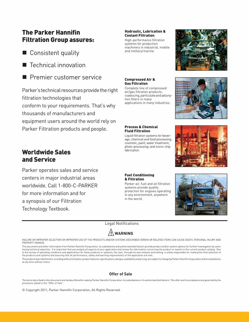
Hydraulic, Lubrication & Coolant Filtration High-performance fi ltration systems for production machinery in industrial, mobile and military/marine.
The Parker Hannifi nFiltration Group assures:
Consistent quality
Technical innovation
Premier customer service
Parker’s technical resources provide the right
fi ltration technologies that
conform to your requirements. That’s why
thousands of manufac turers and
equipment users around the world rely on
Parker Filtration products and people.
Worldwide Sales and Service
Parker operates sales and service
centers in major industrial areas
worldwide. Call 1-800-C-PARKER
for more information and for
a synopsis of our Filtration
Technology Textbook.
© Copyright 2011, Parker Hannifi n Corporation, All Rights Reserved.
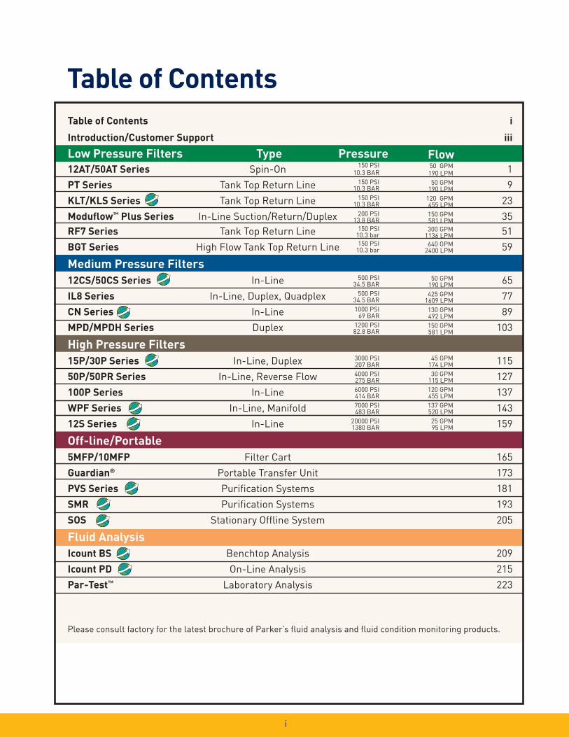
Compressed Air &Gas FiltrationComplete line of compressed air/gas fi ltration products; coal escing, particulate and adsorp-tion fi lters in many applications in many industries.
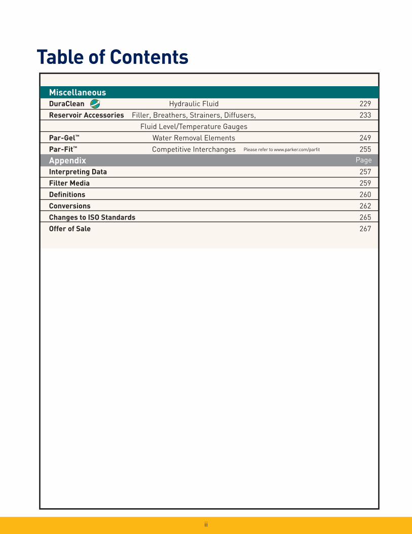
Process & ChemicalFluid FiltrationLiquid fi ltration systems for bever-age, chemical and food processing; cosmetic, paint, water treatment; photo-processing; and micro-chip fabrication.
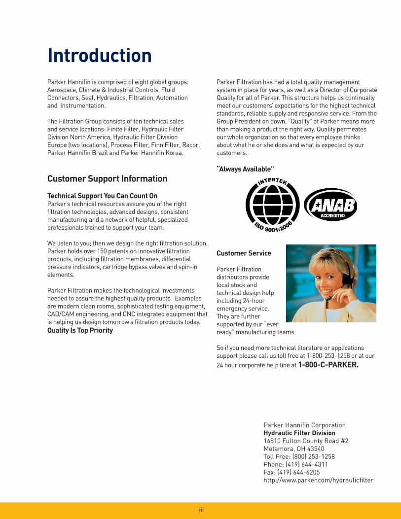
Fuel Conditioning & FiltrationParker air, fuel and oil fi ltration systems provide quality pro tection for engines operatingin any environment, anywhere
in the world.
Legal Notifi cations
!
i
Table of Contents
Pressure150 PSI
10.3 BAR
150 PSI10.3 BAR
150 PSI10.3 BAR
200 PSI13.8 BAR
150 PSI10.3 bar
150 PSI10.3 bar
FlowType
Please consult factory for the latest brochure of Parker’s fl uid analysis and fl uid condition monitoring products.
500 PSI34.5 BAR
500 PSI34.5 BAR
1000 PSI69 BAR
1200 PSI82.8 BAR
50 GPM190 LPM
50 GPM190 LPM
120 GPM455 LPM
150 GPM581 LPM
300 GPM1136 LPM
640 GPM2400 LPM
50 GPM190 LPM
425 GPM1609 LPM
130 GPM492 LPM
150 GPM581 LPM
Table of Contents i
Introduction/Customer Support iii
Low Pressure Filters
12AT/50AT Series Spin-On 1
PT Series Tank Top Return Line 9
KLT/KLS Series Tank Top Return Line 23
Modufl ow™ Plus Series In-Line Suction/Return/Duplex 35
RF7 Series Tank Top Return Line 51
BGT Series High Flow Tank Top Return Line 59
Medium Pressure Filters
12CS/50CS Series In-Line 65
IL8 Series In-Line, Duplex, Quadplex 77
CN Series In-Line 89
MPD/MPDH Series Duplex 103
High Pressure Filters
15P/30P Series In-Line, Duplex 115
50P/50PR Series In-Line, Reverse Flow 127
100P Series In-Line 137
WPF Series In-Line, Manifold 143
12S Series In-Line 159
Off-line/Portable
5MFP/10MFP Filter Cart 165
Guardian® Portable Transfer Unit 173
PVS Series Purifi cation Systems 181
SMR Purifi cation Systems 193
SOS Stationary Offl ine System 205
Fluid Analysis
Icount BS Benchtop Analysis 209
Icount PD On-Line Analysis 215
Par-Test™ Laboratory Analysis 223
3000 PSI207 BAR
4000 PSI275 BAR
6000 PSI414 BAR
7000 PSI483 BAR
20000 PSI1380 BAR
45 GPM174 LPM
30 GPM115 LPM
120 GPM455 LPM
137 GPM520 LPM
25 GPM95 LPM
ii
Table of Contents
Appendix
Interpreting Data 257
Filter Media 259
Defi nitions 260
Conversions 262
Changes to ISO Standards 265
Offer of Sale 267
Page
Miscellaneous
DuraClean Hydraulic Fluid 229
Reservoir Accessories Filler, Breathers, Strainers, Diffusers, 233
Fluid Level/Temperature Gauges
Par-Gel™ Water Removal Elements 249
Par-Fit™ Competitive Interchanges 255Please refer to www.parker.com/parfi t
iii
Parker Hannifi n Corporation
Hydraulic Filter Division
16810 Fulton County Road #2
Metamora, OH 43540
Toll Free: (800) 253-1258
Phone: (419) 644-4311
Fax: (419) 644-6205
http://www.parker.com/hydraulicfi lter
IntroductionParker Hannifi n is comprised of eight global groups:
Aerospace, Climate & Industrial Controls, Fluid
Connectors, Seal, Hydraulics, Filtration, Automation
and Instrumentation.
The Filtration Group consists of ten technical sales
and service locations: Finite Filter, Hydraulic Filter
Division North America, Hydraulic Filter Division
Europe (two locations), Process Filter, Finn Filter, Racor,
Parker Hannifi n Brazil and Parker Hannifi n Korea.
Customer Support Information
Technical Support You Can Count OnParker’s technical resources assure you of the right
fi ltration technologies, advanced designs, consistent
manufacturing and a network of helpful, specialized
professionals trained to support your team.
We listen to you; then we design the right fi ltration solution.
Parker holds over 150 patents on innovative fi ltration
products, including fi ltration membranes, differential
pressure indicators, cartridge bypass valves and spin-in
elements.
Parker Filtration makes the technological investments
needed to assure the highest quality products. Examples
are modern clean rooms, sophisticated testing equipment,
CAD/CAM engineering, and CNC integrated equipment that
is helping us design tomorrow’s fi ltration products today.
Quality Is Top Priority
Parker Filtration has had a total quality management
system in place for years, as well as a Director of Corporate
Quality for all of Parker. This structure helps us continually
meet our customers’ expectations for the highest technical
standards, reliable supply and responsive service. From the
Group President on down, “Quality” at Parker means more
than making a product the right way. Quality permeates
our whole organization so that every employee thinks
about what he or she does and what is expected by our
customers.
“Always Available”
Customer Service
Parker Filtration
distributors provide
local stock and
technical design help
including 24-hour
emergency service.
They are further
supported by our “ever
ready” manufacturing teams.
So if you need more technical literature or applications
support please call us toll free at 1-800-253-1258 or at our
24 hour corporate help line at 1-800-C-PARKER.

Notes
iiii
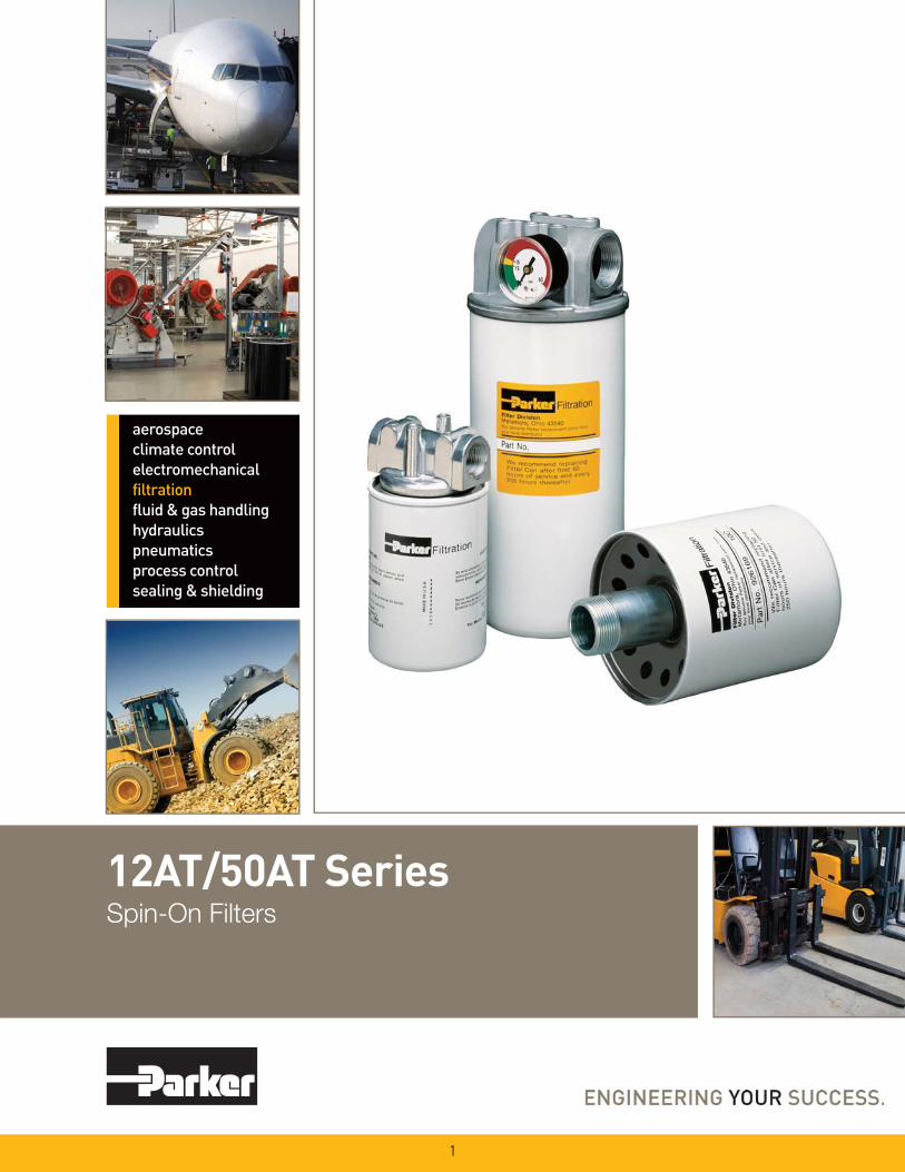
12AT/50AT SeriesSpin-On Filters
1
2
12AT/50AT SeriesSpin-On Filters
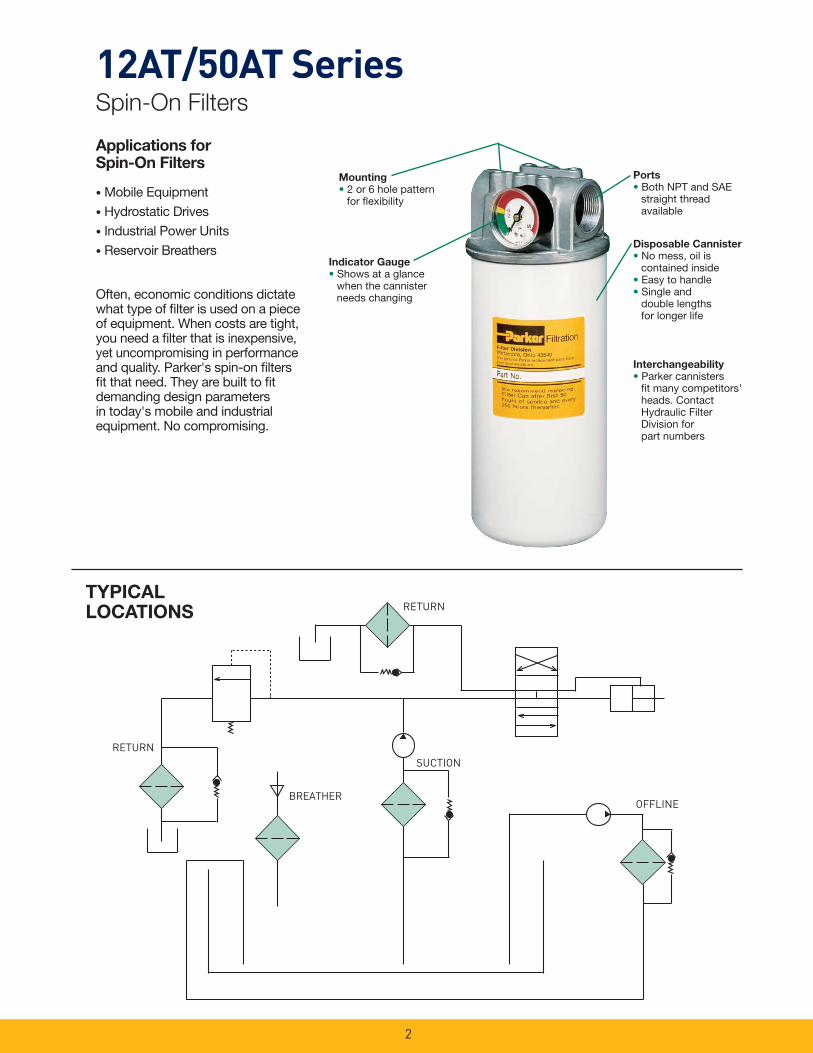
Applications forSpin-On Filters
• Mobile Equipment
• Hydrostatic Drives
• Industrial Power Units
• Reservoir Breathers
Often, economic conditions dictate what type of fi lter is used on a piece of equipment. When costs are tight, you need a fi lter that is inexpensive, yet uncompromising in performance and quality. Parker's spin-on fi lters fi t that need. They are built to fi t demanding design parameters in today's mobile and industrial equipment. No compromising.
Mounting
• 2 or 6 hole pattern for fl exibility
Indicator Gauge
• Shows at a glance when the cannister needs changing
BREATHER
RETURN
RETURNSUCTION
OFFLINE
TYPICAL LOCATIONS
Disposable Cannister
• No mess, oil is contained inside• Easy to handle• Single and
double lengths for longer life
Ports
• Both NPT and SAE straight thread available
Interchangeability
• Parker cannisters fi t many competitors' heads. Contact Hydraulic Filter Division for part numbers
3
03C 10C 25C
10B 20B
(PSI
)P
RES
SUR
E D
RO
P(B
AR)
(GPM) FLOW (LPM)
0 7 14 21 28 35 42 49 56 63 .0
0 2 4 6 8 10 12 14 16 18
.70
.60
.50
.40
.30
.20
.10
.0
150 SUS
12AT ASSEMBLY
(PSI
)P
RES
SUR
E D
RO
P(B
AR
)
(GPM) FLOW (LPM)
0 7 14 21 28 35 42 49 56 63 .0
0 2 4 6 8 10 12 14 16 18
.70
.60
.50
.40
.30
.20
.10
.0
150 SUS
12AT ASSEMBLY 20B10B
25C10C
03B 10B
20B
10C
150 SUS
.70
.60
.50
.40
.30
.20
.10
.0
10
8
6
4
2
00 5 10 15 20 25 30 35 40 45
(PSI
)P
RES
SUR
E D
RO
P(B
AR)
(GPM) FLOW (LPM)
0 15 30 45 60 75 90 105 120 135
50AT-2 ASSEMBLY
150 165 180
50
150 SUS
.70
.60
.50
.40
.30
.20
.10
.0
10
8
6
4
2
00 5 10 15 20 25 30 35 40 45
(PSI
)P
RES
SUR
E D
RO
P(B
AR
)
(GPM) FLOW (LPM)
0 15 30 45 60 75 90 105 120 135
50AT-1 ASSEMBLY
150 165 180
50
03C10
8
6
4
2
0
10
8
6
4
2
0
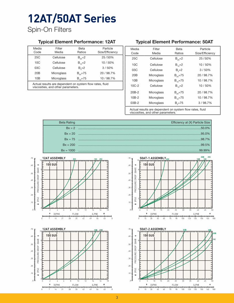
Typical Element Performance: 12AT Typical Element Performance: 50AT
MediaCode
FilterMedia
BetaRatios
ParticleSize/Effi ciency
25C Cellulose B25=2 25 / 50%
10C Cellulose B10=2 10 / 50%
03C Cellulose B3=2 3 / 50%
20B Microglass B20=75 20 / 98.7%
10B Microglass B10=75 10 / 98.7%
MediaCode
FilterMedia
BetaRatios
ParticleSize/Effi ciency
25C Cellulose B25=2 25 / 50%
10C Cellulose B10=2 10 / 50%
03C Cellulose B3=2 3 / 50%
20B Microglass B20=75 20 / 98.7%
10B Microglass B10=75 10 / 98.7%
10C-2 Cellulose B10=2 10 / 50%
20B-2 Microglass B20=75 20 / 98.7%
10B-2 Microglass B10=75 10 / 98.7%
03B-2 Microglass B3=75 3 / 98.7%
Beta Rating Effi ciency at (X) Particle Size
Bx = 2 ................................................................................................................................................50.0%
Bx = 20 ................................................................................................................................................95.0%
Bx = 75 ................................................................................................................................................98.7%
Bx = 200 ................................................................................................................................................99.5%
Bx = 1000 ..............................................................................................................................................99.99%
Actual results are dependent on system fl ow rates, fl uid viscosities, and other parameters.
Actual results are dependent on system fl ow rates, fl uid viscosities, and other parameters.
12AT/50AT SeriesSpin-On Filters

4
12AT/50AT SeriesSpin-On Filters
Installation andSpecifi cation DataModel 12AT
Pressure Ratings:Maximum Allowable Operating Pressure (MAOP): 150 psi (10.3 bar)
Design Safety Factor: 2.5:1
Operating Temperatures:-40ºF to 225ºF (-40ºC to 107ºC)
Element Collapse Rating:100 psid minimum
Element Condition Indicators:Gauge: Color coded 15/25 psi
Gauge: Color coded vacuum
Pressure Switch: Normally open 20 +/- 2 psi 5 Amps @ 24 VDC
Vacuum Switch: Normally open 5" +/- 1" Hg 1.0 Amp @ 120 VAC
Filter Material: Head: AluminumCannister: Low Carbon Steel
Shipping Weights (approximate):1.6 lbs.
67.822.67
MAX
95.253.75
38.101.50
95.003.74
¼ - 20 UNC x .31 MINTHREAD DEPTH2-TOTAL
47.621.875
23.62.93
172.976.81
MAX
148.845.68
12.19.48
PORTS (BOTH ENDS)¾"-14 NPTF
OR ¾" SAE - 12
MINIMUM REMOVAL CLEAR-ANCE
15.7.62
27.431.08
OPTIONAL 1/8 - 27 NPTGAUGE PORT (4 PLACES)
TORQUE TO 2 - 3 TURNS FROM FINGER TIGHT
OUTLETINLET
Linear Measure: millimeterinch
Drawings are for reference only. Contact factory for current version.

5
12AT/50AT SeriesSpin-On Filters
Filter Material: Head: AluminumCannister: Low Carbon Steel
Shipping Weights (approximate):Single length: 3.7 lbs.Double length: 5.3 lbs.
Element Collapse Rating:100 psid minimum
Element Condition Indicators:Gauge: Color coded 15/25 psi
Gauge: Color coded vacuum
Pressure Switch: Normally open 20 +/- 2 psi 5 Amps @ 24 VDC
Vacuum Switch: Normally open 5" +/- 1" Hg 1.0 Amp @ 120 VAC
Installation andSpecifi cation DataModel 50AT
Pressure Ratings:Maximum Allowable Operating Pressure (MAOP): 150 psi (10.3 bar)
Design Safety Factor: 2.5:1
Operating Temperatures:-40°F to 2250F (-400 C to 1070C)
Ports: (both ends)1¼"-11½" NPTF
or1¼" SAE-20
Linear Measure: millimeterinch
Drawings are for reference only. Contact factory for current version.
OPTIONAL 1/8 - 27 NPTGAUGE PORT (4 PLACES)
TORQUE TO 5 - 6 INCH POUNDS
6
12AT/50AT SeriesSpin-On Filters
0 10 20 30 40 50 60 70 80 90 100
DIF
FER
ENTI
AL
PR
ESSU
RE
(IN
H2O
)
AIR FLOW (SCFM)
12AT
0
1
2
3
4
5
6
7
8
9
10
0
1
2
3
4
5
6
7
8
9
10
0 100 200 300 400 500 600
50AT.1
.2
.3
.4
0 10 20 30 40 50 60 70 80 90 100
OIL LEVEL CHANGE RATE (GPM)
12AT
50AT
DIF
FER
ENTI
AL
PR
ESSU
RE
(PSI
)
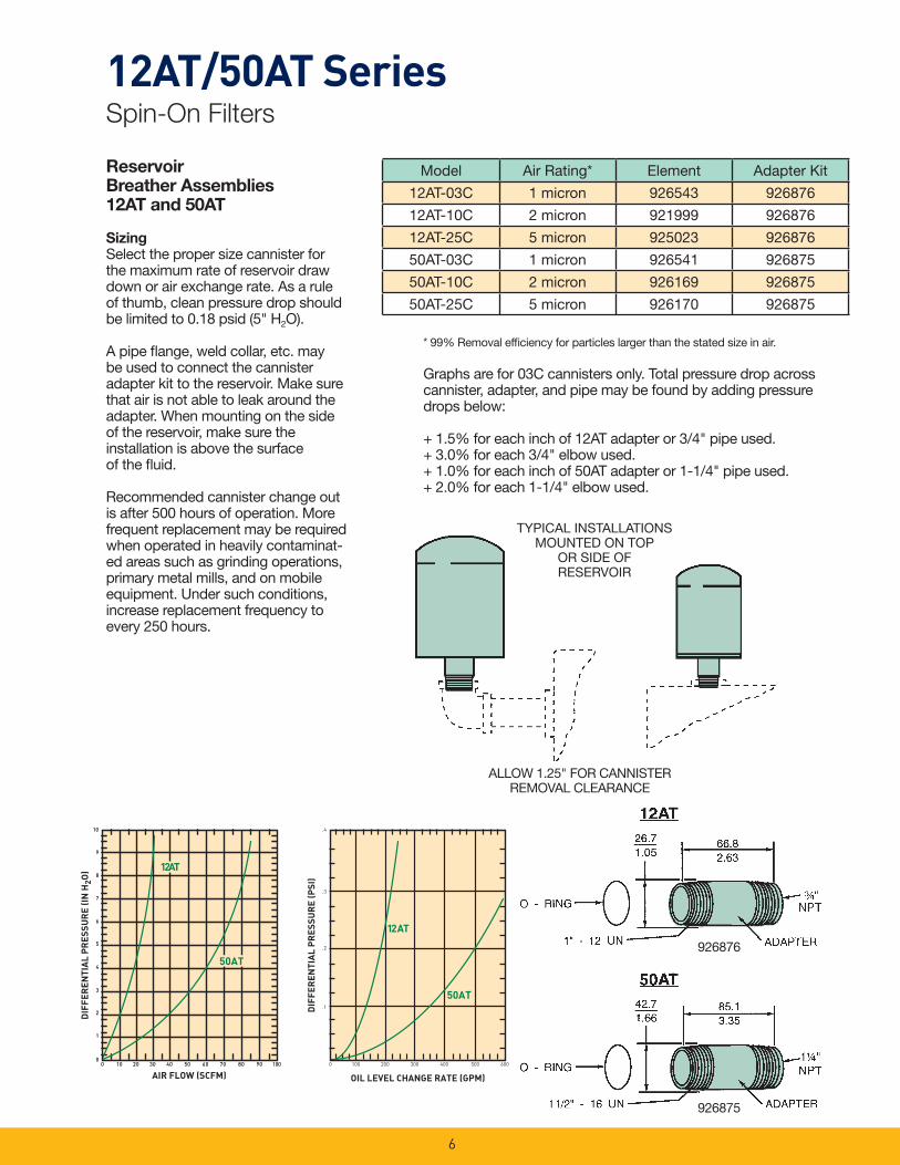
ReservoirBreather Assemblies12AT and 50AT
SizingSelect the proper size cannister for the maximum rate of reservoir draw down or air exchange rate. As a rule of thumb, clean pressure drop should be limited to 0.18 psid (5" H2O).
A pipe fl ange, weld collar, etc. may be used to connect the cannister adapter kit to the reservoir. Make sure that air is not able to leak around the adapter. When mounting on the side of the reservoir, make sure the installation is above the surface of the fl uid.
Recommended cannister change out is after 500 hours of operation. More frequent replacement may be required when operated in heavily contaminat-ed areas such as grinding operations, primary metal mills, and on mobile equipment. Under such conditions, increase replacement frequency to every 250 hours.
* 99% Removal effi ciency for particles larger than the stated size in air.
Graphs are for 03C cannisters only. Total pressure drop across cannister, adapter, and pipe may be found by adding pressure drops below:
+ 1.5% for each inch of 12AT adapter or 3/4" pipe used.+ 3.0% for each 3/4" elbow used.+ 1.0% for each inch of 50AT adapter or 1-1/4" pipe used.+ 2.0% for each 1-1/4" elbow used.
TYPICAL INSTALLATIONSMOUNTED ON TOP
OR SIDE OFRESERVOIR
ALLOW 1.25" FOR CANNISTERREMOVAL CLEARANCE
Model Air Rating* Element Adapter Kit
12AT-03C 1 micron 926543 926876
12AT-10C 2 micron 921999 926876
12AT-25C 5 micron 925023 926876
50AT-03C 1 micron 926541 926875
50AT-10C 2 micron 926169 926875
50AT-25C 5 micron 926170 926875
926876
926875
7
12AT/50AT SeriesSpin-On Filters
1/8 NPTTHREAD
1.5840.1
.369.1
1.5138.4
Linear Measure = inches mm
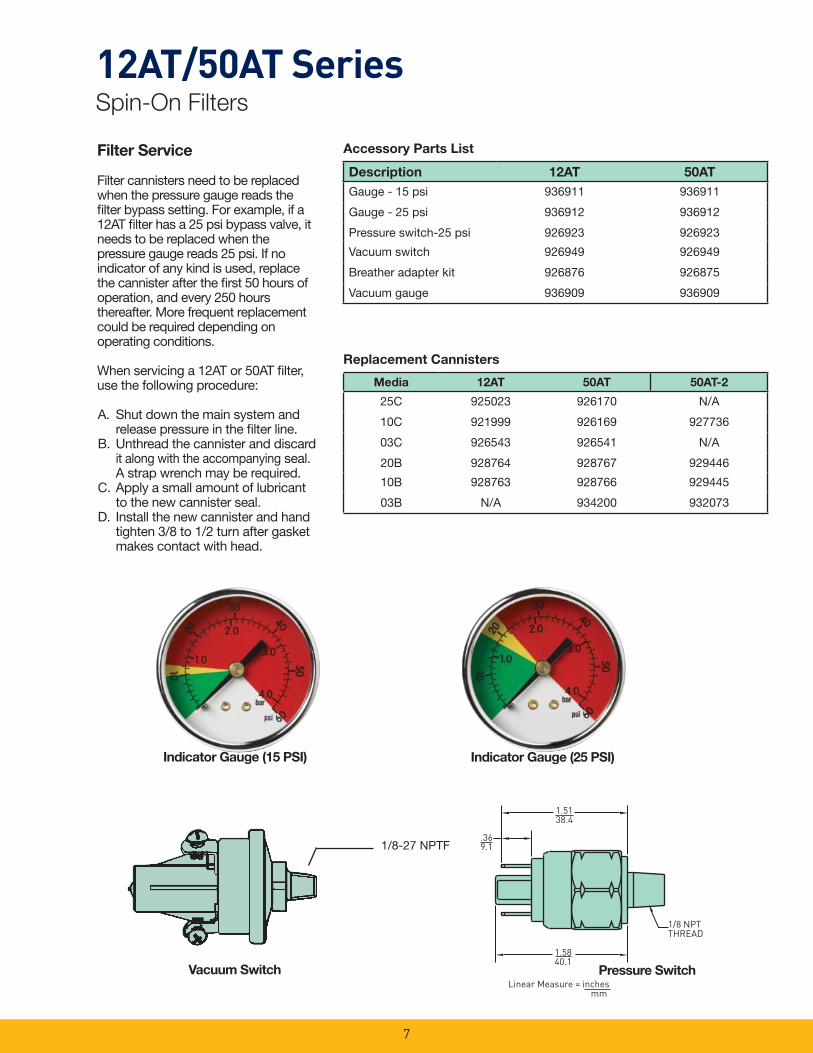
Filter Service
Filter cannisters need to be replaced when the pressure gauge reads the fi lter bypass setting. For example, if a 12AT fi lter has a 25 psi bypass valve, it needs to be replaced when the pressure gauge reads 25 psi. If no indicator of any kind is used, replace the cannister after the fi rst 50 hours of operation, and every 250 hours thereafter. More frequent replacement could be required depending on operating conditions.
When servicing a 12AT or 50AT fi lter, use the following procedure:
A. Shut down the main system and release pressure in the fi lter line.
B. Unthread the cannister and discard it along with the accompanying seal. A strap wrench may be required.
C. Apply a small amount of lubricant to the new cannister seal.
D. Install the new cannister and hand tighten 3/8 to 1/2 turn after gasket makes contact with head.
Accessory Parts List
Replacement Cannisters
1/8-27 NPTF
Description 12AT 50AT
Gauge - 15 psi 936911 936911
Gauge - 25 psi 936912 936912
Pressure switch-25 psi 926923 926923
Vacuum switch 926949 926949
Breather adapter kit 926876 926875
Vacuum gauge 936909 936909
Media 12AT 50AT 50AT-2
25C 925023 926170 N/A
10C 921999 926169 927736
03C 926543 926541 N/A
20B 928764 928767 929446
10B 928763 928766 929445
03B N/A 934200 932073
Indicator Gauge (15 PSI) Indicator Gauge (25 PSI)
Pressure SwitchVacuum Switch

8
12AT/50AT SeriesSpin-On Filters
How To OrderSelect the desired symbol (in the correct position) to construct a model code.
Example:
BOX 1 BOX 2 BOX 3 BOX 4 BOX 5 BOX 6 BOX 7 BOX 8
50AT 2 10C N 25 DD N
BOX 1: Seals Symbol Description
None Buna
BOX 2: Symbol Description
12AT Spin-on (¾" nom.)
50AT Spin-on (1¼" nom.)
BOX 3: Length Symbol Description
None Single lengthcannister
2 Double length cannister (50AT only)
BOX 4: Cannister Media Symbol Description
25C* Cellulose
10C Cellulose
03C* Cellulose
20B Microglass
10B Microglass
03B ** Microglass
BOX 5: Indicator SymbolDescription
N None
BOX 6: Bypass Setting Symbol Description
25 25 psid
15 15 psid
3 3 psid
X No bypass
BOX 7: Ports Symbol Description
12AT
BB 3/4" NPTF
MM SAE-12
50AT
DD 1-1/4" NPTF
OO SAE-20
BOX 8:Symbol Description
N None
H Inlet and outlet, both
sides (all ports drilled and
tapped)
* Not available in 50AT-2** Not available in 12AT
NOTE: Gauges must be ordered separately.
Please note the bolded options refl ect standard options with a reduced lead-time. Consult factory on all other lead-time options.
Basic Assembly
Gauge Port Location

PT SeriesTank Top Filters
9

10
PT SeriesApplications
The new PT series fi lter is available in two diameters and three lengths for fl ow ranges from 5-50 gpm. The PT2 and PT4 fi lter cartridges utilize Microglass media in 2, 5, 10 and 20 microns for the industry’s best particle removal effi ciency and retention.
This unique design simply threads into a ported weld ring or fl ange, which can be bolted to a metal reservoir.
The disposable fi lter cartridge is a single-piece construction, which incorporates the nylon cover and integral 25 psi bypass valve. The fl ow path is inside-out and requires no special tools for service.
This concept assures minimal installation costs with the least space requirements for return line applications.
The PT Series fi lter combines high effi ciency Microglass fi ltration with low cost installation featured in a new patented element design.
Together we can…
Preserve the environment. Minimize waste and promote energy effi ciency.
Achieve worldwide fi ltration solutions. Build global confi dence.
Redefi ne new limits. Forge ahead with advanced technology.
Keep contamination under control. Reduce maintenance costs.
Enhance total system reliability. Focus on customer satisfaction.
Reach optimum potential. Drill to greater depths.
…engineer your success.
Typical Applications
• Turf Maintenance
• Material Handling
• Aerial Lifts
• Fan Drive
11
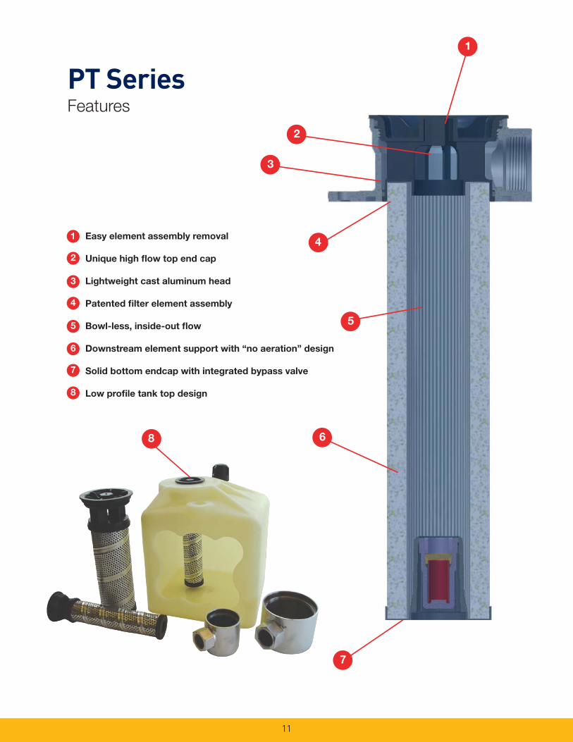
PT SeriesFeatures
1 Easy element assembly removal
2 Unique high fl ow top end cap
3 Lightweight cast aluminum head
4 Patented fi lter element assembly
5 Bowl-less, inside-out fl ow
Downstream element support with “no aeration” design
Solid bottom endcap with integrated bypass valve
Low profi le tank top design
2
3
4
6
5
7
8
8
4
2
1
5
7
6
3
12
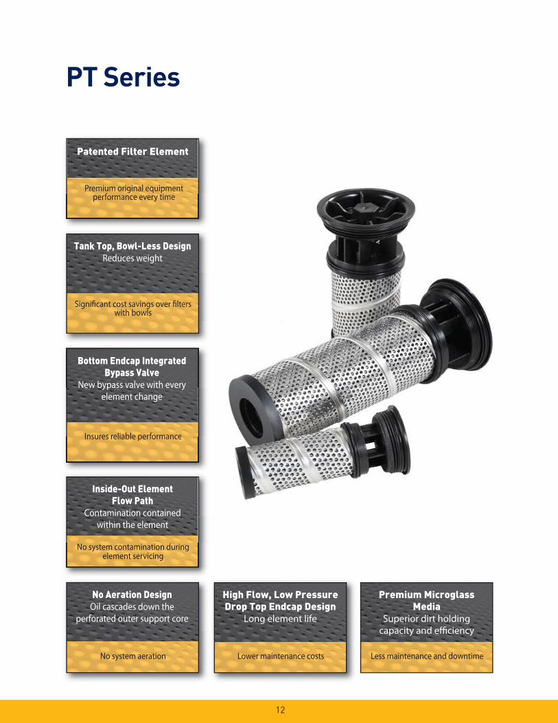
PT Series
Patented Filter Element
Premium original equipment performance every time
Bottom Endcap Integrated
Bypass Valve
New bypass valve with every element change
Insures reliable performanceInsures reliable performance
No system contamination during element servicing
Inside-Out Element
Flow Path
Contamination contained within the element
No system contamination during element servicing
No system aeration
No Aeration Design
Oil cascades down theperforated outer support core
performance every time
Bottom Endcap Integrated
Bypass Valve
New bypass valve with every
Significant cost savings over filters with bowls
Tank Top, Bowl-Less Design
Reduces weight
Lower maintenance costs
High Flow, Low Pressure
Drop Top Endcap Design
Long element life
Less maintenance and downtime
Premium Microglass
Media
Superior dirt holdingcapacity and efficiency
13
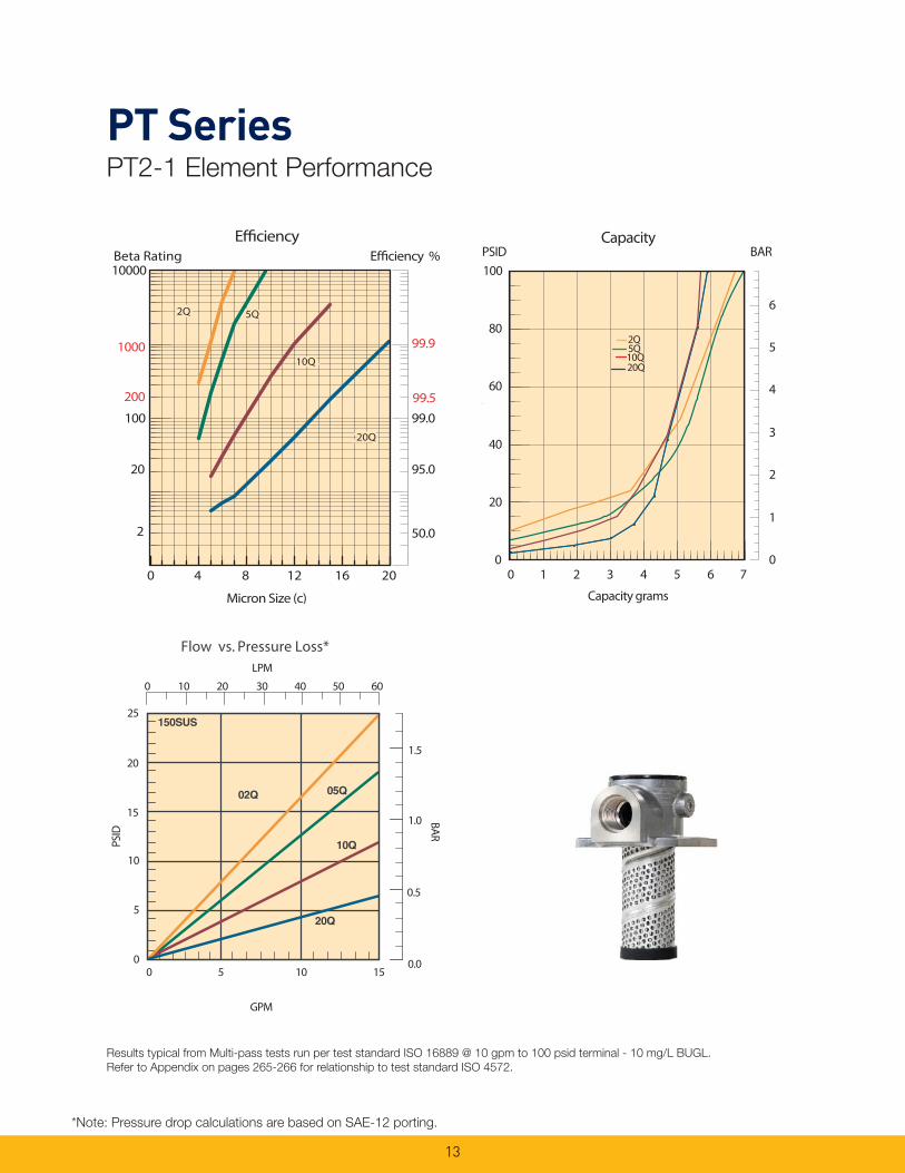
PT SeriesPT2-1 Element Performance
Results typical from Multi-pass tests run per test standard ISO 16889 @ 10 gpm to 100 psid terminal - 10 mg/L BUGL.
Refer to Appendix on pages 265-266 for relationship to test standard ISO 4572.
*Note: Pressure drop calculations are based on SAE-12 porting.
Efficiency %Efficiency
Beta Rating
1000
10000
99.9
99.599.0100
200
20
2 50.0
95.0
Micron Size (c)
2Q
10Q
20Q
5Q
0 4 8 12 16 20
Flow vs. Pressure Loss*
25
20
15
10
5
0
1.5
1.0
0.5
0.00 5 10 15
GPM
LPM
0 10 20 30 40 50 60
PSID
BAR
PSID BARCapacity
20Q10Q5Q2Q
0
1
2
3
4
5
6
0
20
40
60
80
100
s
0 1 2 3 4 5 6 7
Capacity grams
14
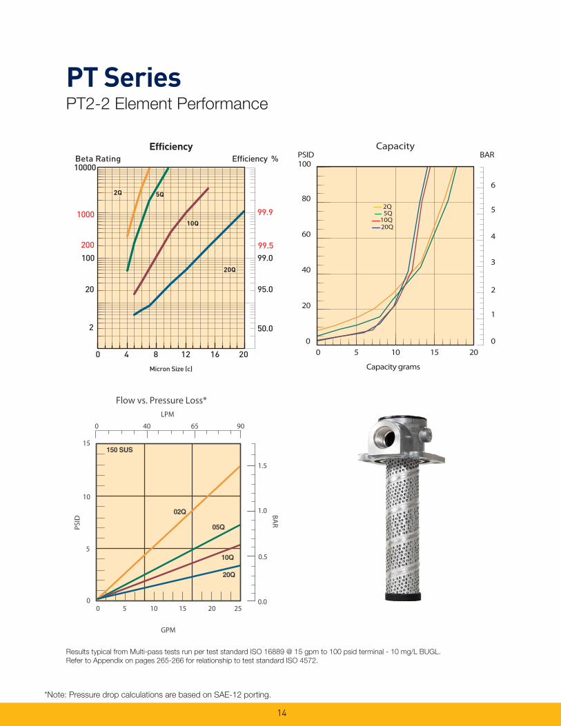
PT SeriesPT2-2 Element Performance
Results typical from Multi-pass tests run per test standard ISO 16889 @ 15 gpm to 100 psid terminal - 10 mg/L BUGL.
Refer to Appendix on pages 265-266 for relationship to test standard ISO 4572.
*Note: Pressure drop calculations are based on SAE-12 porting.
PSID BARCapacity
20Q
2Q5Q
10Q
0
1
2
3
4
5
6
0
20
40
60
80
100
0 5 10 15 20
Capacity grams
LPM
PSID
BAR
GPM
0 5 10 15 20 250
5
10
15
0.0
0.5
1.0
1.5
0 40 65 90
Flow vs. Pressure Loss*

15
PT SeriesPT4-1 Element Performance
Results typical from Multi-pass tests run per test standard ISO 16889 @ 15 gpm to 100 psid terminal - 10 mg/L BUGL.
Refer to Appendix on pages 265-266 for relationship to test standard ISO 4572.
*Note: Pressure drop calculations are based on SAE-16 porting.
BARPSIDCapacity
0
1
2
3
4
5
6
0
20
40
60
80
100
0 10 20 30 40Capacity grams
2Q5Q
10Q20Q
PSI
D B
AR
GPM
25
20
15
10
5
0
1.5
1.0
0.5
0.0
0 50 100 150 200
Flow vs. Pressure Loss*LPM
0 10 20 30 40 50
16
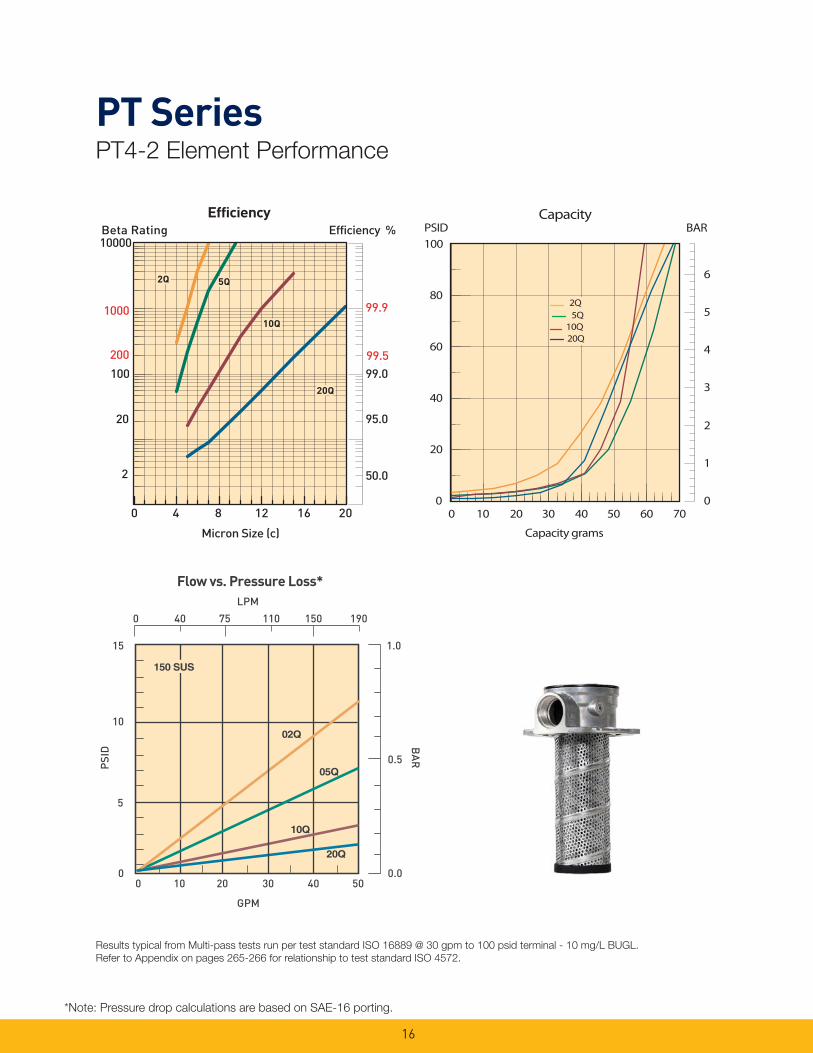
PT SeriesPT4-2 Element Performance
Results typical from Multi-pass tests run per test standard ISO 16889 @ 30 gpm to 100 psid terminal - 10 mg/L BUGL.
Refer to Appendix on pages 265-266 for relationship to test standard ISO 4572.
*Note: Pressure drop calculations are based on SAE-16 porting.
BARPSIDCapacity
0
1
2
3
4
5
6
0
20
40
60
80
100
0 10 20 30 40 50 60 70
Capacity grams
2Q
10Q20Q
5Q
0
5
10
15
0 10 20 30 40 50
1.0
0.5
0.0
PSI
D B
AR
LPM
0 40 75 110 150 190
Flow vs. Pressure Loss*
GPM
17
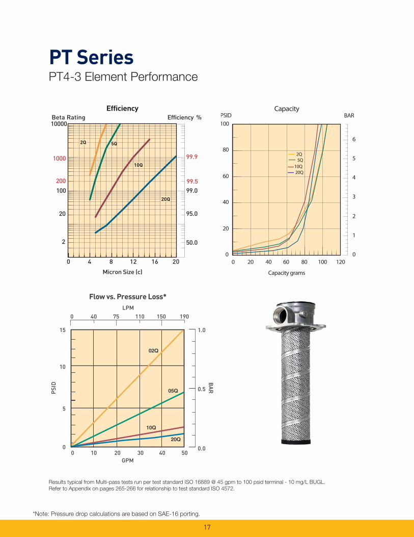
PT SeriesPT4-3 Element Performance
Results typical from Multi-pass tests run per test standard ISO 16889 @ 45 gpm to 100 psid terminal - 10 mg/L BUGL.
Refer to Appendix on pages 265-266 for relationship to test standard ISO 4572.
*Note: Pressure drop calculations are based on SAE-16 porting.
BARPSIDCapacity
2Q
10Q20Q
5Q
0
1
2
3
4
5
6
0
20
40
60
80
100
0 20 40 60 80 100 120
Capacity grams
LPM
Flow vs. Pressure Loss*
0 40 75 110 150 190
0.5
0.0
1.0
PSI
D B
AR
15
10
5
0 0 10 20 30 40 50
GPM
18
Drawings are for reference only. Contact factory for current version.
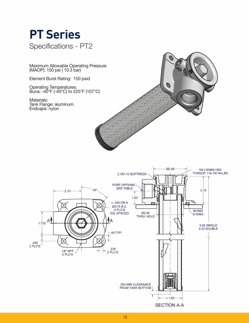
PT SeriesSpecifi cations - PT2
Maximum Allowable Operating Pressure (MAOP): 150 psi ( 10.3 bar)
Element Burst Rating: 150 psid
Operating Temperatures:Buna: -40°F (-40°C) to 225°F (107°C)
Materials:Tank Flange: aluminumEndcaps: nylon

19
Drawings are for reference only. Contact factory for current version.
PT SeriesSpecifi cations - PT4
SECTION A-A
A A
4.06Ø
1/8-27 PTF2 PLC'S
REF.
3.500-10 BUTTRESS
14.55`.060
6.20± .060 SINGLE9.79± .060 DOUBLE
TRIPLE
2.41
1.11
3.09Ø
2.70
.400 MIN CLEARANCEFROM TANK BOTTOM
PORT OPTIONS -SEE TABLE
2.045
36°
n.345 ON A Ø5.50 B.C.
5 PLC'SEQ. SPACED
1/8-27 PTF2 PLC'S
.90 DIA FLAT5 PLC'S
15/16 (24MM) HEXTORQUE 200-240 IN-LBS 3.33Ø
THRU. HOLE
941664O-RING
Maximum Allowable Operating Pressure (MAOP): 150 psi ( 10.3 bar)
Element Burst Rating: 150 psid
Operating Temperatures:Buna: -40°F (-40°C) to 225°F (107°C)
Materials:Tank Flange: aluminumEndcaps: nylon
20
1.5138.4
1.5840.1
.369.1
1/8 NPTTHREAD
inchesmm
Linear measure =
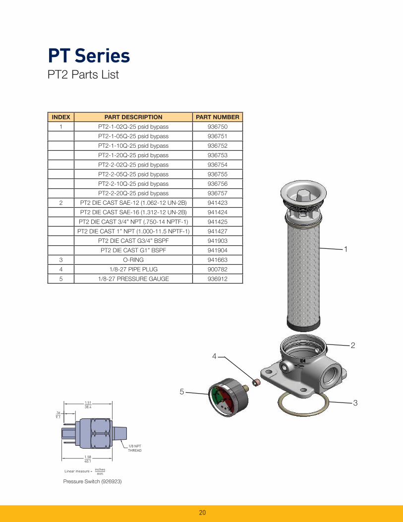
INDEX PART DESCRIPTION PART NUMBER
1 PT2-1-02Q-25 psid bypass 936750
PT2-1-05Q-25 psid bypass 936751
PT2-1-10Q-25 psid bypass 936752
PT2-1-20Q-25 psid bypass 936753
PT2-2-02Q-25 psid bypass 936754
PT2-2-05Q-25 psid bypass 936755
PT2-2-10Q-25 psid bypass 936756
PT2-2-20Q-25 psid bypass 936757
2 PT2 DIE CAST SAE-12 (1.062-12 UN-2B) 941423
PT2 DIE CAST SAE-16 (1.312-12 UN-2B) 941424
PT2 DIE CAST 3/4” NPT (.750-14 NPTF-1) 941425
PT2 DIE CAST 1” NPT (1.000-11.5 NPTF-1) 941427
PT2 DIE CAST G3/4” BSPF 941903
PT2 DIE CAST G1” BSPF 941904
3 O-RING 941663
4 1/8-27 PIPE PLUG 900782
5 1/8-27 PRESSURE GAUGE 936912
1
2
3
5
4
PT SeriesPT2 Parts List
Pressure Switch (926923)
21
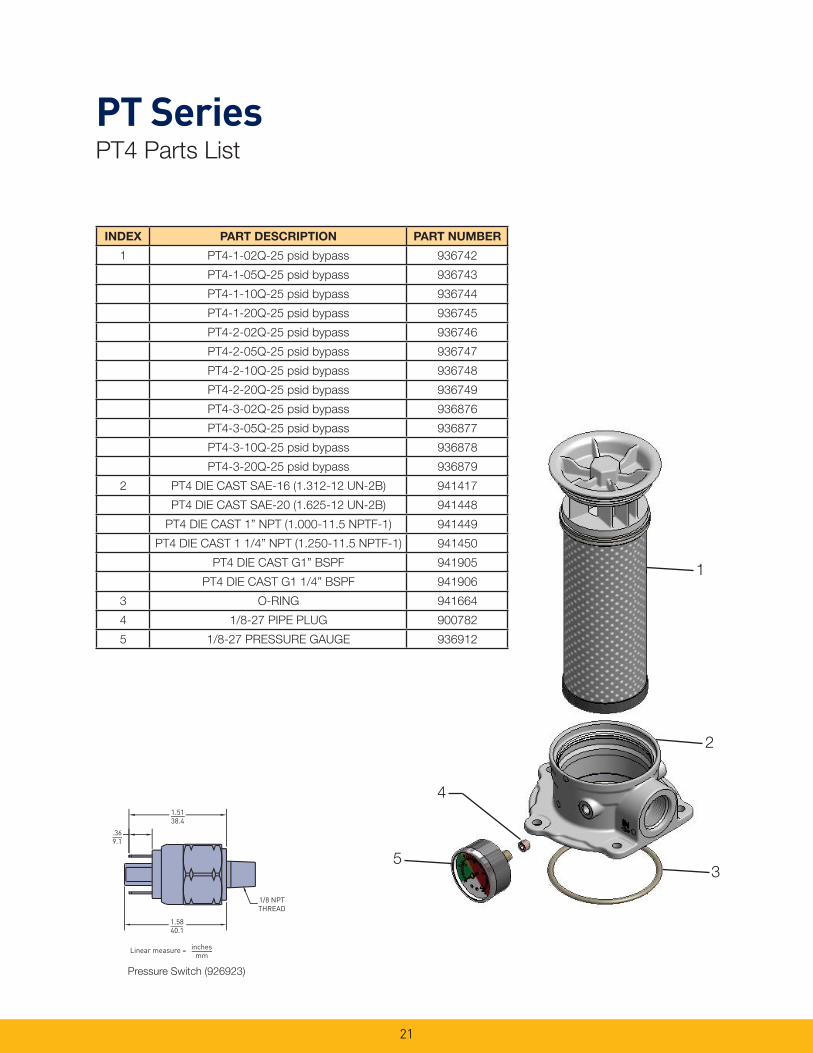
PT SeriesPT4 Parts List
INDEX PART DESCRIPTION PART NUMBER
1 PT4-1-02Q-25 psid bypass 936742
PT4-1-05Q-25 psid bypass 936743
PT4-1-10Q-25 psid bypass 936744
PT4-1-20Q-25 psid bypass 936745
PT4-2-02Q-25 psid bypass 936746
PT4-2-05Q-25 psid bypass 936747
PT4-2-10Q-25 psid bypass 936748
PT4-2-20Q-25 psid bypass 936749
PT4-3-02Q-25 psid bypass 936876
PT4-3-05Q-25 psid bypass 936877
PT4-3-10Q-25 psid bypass 936878
PT4-3-20Q-25 psid bypass 936879
2 PT4 DIE CAST SAE-16 (1.312-12 UN-2B) 941417
PT4 DIE CAST SAE-20 (1.625-12 UN-2B) 941448
PT4 DIE CAST 1” NPT (1.000-11.5 NPTF-1) 941449
PT4 DIE CAST 1 1/4” NPT (1.250-11.5 NPTF-1) 941450
PT4 DIE CAST G1” BSPF 941905
PT4 DIE CAST G1 1/4” BSPF 941906
3 O-RING 941664
4 1/8-27 PIPE PLUG 900782
5 1/8-27 PRESSURE GAUGE 936912
1
2
3
4
5
1.5138.4
1.5840.1
.369.1
1/8 NPTTHREAD
inchesmm
Linear measure =
Pressure Switch (926923)
22
Global products as identifi ed are offered worldwide through all Parker locations and utilize a common ordering code.
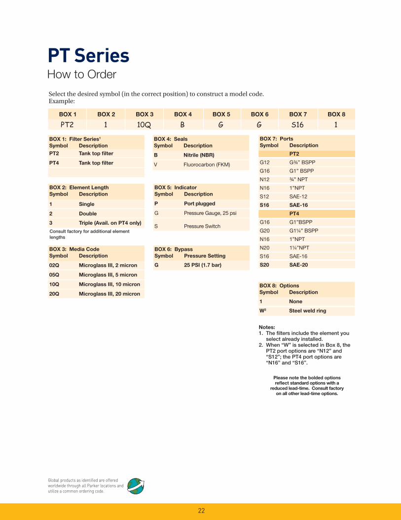
PT SeriesHow to Order
Select the desired symbol (in the correct position) to construct a model code. Example:
BOX 1 BOX 2 BOX 3 BOX 4 BOX 5 BOX 6 BOX 7 BOX 8
PT2 1 10Q B G G S16 1
BOX 1: Filter Series1
Symbol Description
PT2 Tank top fi lter
PT4 Tank top fi lter
BOX 5: Indicator
Symbol Description
P Port plugged
G Pressure Gauge, 25 psi
S Pressure Switch
BOX 4: Seals
Symbol Description
B Nitrile (NBR)
V Fluorocarbon (FKM)
BOX 8: Options
Symbol Description
1 None
W2 Steel weld ring
BOX 3: Media Code
Symbol Description
02Q Microglass III, 2 micron
05Q Microglass III, 5 micron
10Q Microglass III, 10 micron
20Q Microglass III, 20 micron
Please note the bolded options
refl ect standard options with a
reduced lead-time. Consult factory
on all other lead-time options.
BOX 6: Bypass
Symbol Pressure Setting
G 25 PSI (1.7 bar)
BOX 2: Element Length
Symbol Description
1 Single
2 Double
3 Triple (Avail. on PT4 only)
BOX 7: Ports
Symbol Description
PT2
G12 G¾ ” BSPP
G16 G1” BSPP
N12 ¾ ” NPT
N16 1”NPT
S12 SAE-12
S16 SAE-16
PT4
G16 G1”BSPP
G20 G1¼ ” BSPP
N16 1”NPT
N20 1¼ ”NPT
S16 SAE-16
S20 SAE-20
Notes:
1. The fi lters include the element you select already installed.
2. When “W” is selected in Box 8, the PT2 port options are “N12” and “S12”; the PT4 port options are “N16” and “S16”.
Consult factory for additional element lengths

KLT and KLS SeriesTank Top Return Line Filters
23

24
KLT/KLS SeriesTank Top Return Line Filters
Parker’s new KLS /KLT Tank Top Return Line Filters are ideally suited for Mobile and Industrial high to medium fl ow return applications, from 30 to 120 GPM. This cost-effective, in-tank fi lter series provides maximum fl ow and dirt holding capacity for longer fi lter element life in a simple, easy-to-install-and-service assembly.
The generous element size with extensive media area ensures continuous fi ltration during cold start up conditions. The inside-to-out fl ow path with closed bottom provides additional assurance that all contaminants remain captured during element service removal. The fi lters have a pressure rating of 150 psi static, a temperature range of -40˚F to 225˚F, and are available in a wide range of high-effi ciency Microglass III media in 2, 5, 10 and 20 micron for all system cleanliness requirements. Bypass valves are built into the element to ensure further performance integrity. A new bypass is provided with each element change. This rugged design meets the needs for the demanding applications in mobile off -highway and on-highway applications for construction equipment, logging, refuse vehicles, mining, oil and gas recovery, marine, and industrial power units.
Feature Advantage Benefi t
• Tank top mounted fi lter • Saves space and reduces mounting hardware
• Lower cost, easy to integrate• KLS model directly retrofi ts
competitive housing
• Two-piece head and element construction perforated with metal outer wrap
• No bowl required• Provides excellent fl ow diffusing,
eliminating aeration
• Reduced cost and assembly weight
• Improved performance
• High effi ciency Microglass media maximizing fi ltration area
• Combines high particle capture effi ciency with high dirt holding capacity and lower P
• Cleaner fl uids, longer lasting with fewer service intervals
• Continuous fi ltration for cold start ups
• Lower operating costs
• Element design includes intergral disposable bypass valve with closed bottom end cap
• New bypass with each element change
• Ensures captured contaminants are removed with each element change
• Ensures reliable bypass performance
• No leakage• Cleaner fl uids reduce risk for
contamination during service
• Magnetic prefi ltration • Removes large ferrous contaminants
• Extends element life• Visual indication of component
wear
• Fill and gauge ports • Add fl uid through high performance fi lter media
• Gauge ports allow for added instrumentation
• Initial fl uid integrity extends system component life
• Monitor element life
Applications for KLT and KLS Filters
• Mobile Equipment
• Construction, Refuse
• Industrial Power Units
• Machine Tool
• Oil Field

25
KLT/KLS SeriesSpecifi cations
Pressure Ratings: Maximum Allowable Operating
Pressure
(MAOP): 150 psi (10.3 bar)
Operating Temperatures:
-40°F (-40°C) to 225°F (107°C)
Element Burst Rating:
150 psid (10.3 bar)
Filtration Rating:
2, 5, 10 & 20 Microns at Beta > 200
Linear Measure: inch (mm)
KLT Weld Plate Drawings
3.4 (86)
¼“ NPT THREAD
½“ NPT CONDUIT CONNECTION
18.0 (457)WIRE LEADSCOMMON BLACKN.O. : REDN.C. : GREEN
18 TO 22 PSI(YELLOW FIELD)
1.89 (48)
22 TO 60 PSI(RED FIELD) 1.06
(27)
2.08(53) .55 (14) SQ.
¼“ NPT THREAD0 TO 18 PSI(GREEN FIELD)
DHOLE IN RESERVOIR
C
THREAD A
B
B
DimensionKLT Filter Model
KLT-2/KLT-4 KLT-7/KLT-8
A 5/16-18 UNC-2A 3/8-16 UNC-2A
B 5.33 (135) 7.15 (182)
C 1.00 (25) 1.00 (25)
D 4.50/3.75 (114/95) 6.25/5.50 (159/140)
Element Condition Indicators:
Gauge: 0-60 psi color codedSwitch: SPDT 5A @ 24 VDC and 250 VAC
Materials:
Head & Cover: Cast Aluminum AlloyBypass Valve: NylonFilter Media: Microglass IIIElement End Caps: Nylon
Weights (approximate):
KLT-2 . . . . . . . . . .3 lbs. (1.36 kg)KLT-4 . . . . . . . . . .4 lbs. (1.81 kg)KLT(S)-7 . . . . . . .8 lbs. (3.63 kg)KLT(S)-8 . . . . . . .10 lbs. (4.54 kg)
Drawings are for reference only. Contact factory for current version.

26
KLT Series Dimensional Drawings
KLT 2 / KLT 4 KLT 7 / KLT 8
3.54 (90)
TORQUE: 7 FT-LB (10 N-m)
6.54 (166)TYP.
SAE-24 STRAIGHT THREADO-RING PORT
.43 (11) DIA. MOUNTING HOLES(4 PLACES) ON 6.89 (175) B.C.RECOMMENDED HEAD TO TANKTORQUE: 30 FT-LB (40 N-m)
CMIN. SERVICE CLEARANCE
¼ NPT PLUGGED GAUGE PORT(S)(3 PLACES)
1.42 (36)
3.66 (93)
DRESERVOIR
CUTOUTDIAMETER
L
1.10 (28)
L
D
RESERVOIR
CUTOUT
DIAMETER
¼ NPT PLUGGED
GAUGE PORT(S)
(3 PLACES)
2.83 (72)
C
MIN. SERVICE
CLEARANCE
.35 (9) DIA. MOUNTING HOLES
(4 PLACES) ON 4.96 (126) B.C.
RECOMMENDED HEAD TO TANK
TORQUE: 11 FT-LB (15 N-m)
SAE-16 STRAIGHT
THREAD O-RING PORT
TORQUE: 3 FT-LB (4 N-m)
2.68 (68)
4.72 (120)TYP
Linear Measure: inch (mm)
DimensionsKLT Filter Model
KLT-2 KLT-4
C 5.75 (146) 9.50 (241)
L 4.16 (106) 7.75 (197)
D3.6 (93)
3.56 (90)
DimensionsKLT Filter Model
KLT-7 KLT-8
C 13.00 (330) 19.25 (489)
L 11.46 (291) 17.70 (450)
D5.36 (136)
5.26 (133)
Drawings are for reference only. Contact factory for current version.
27
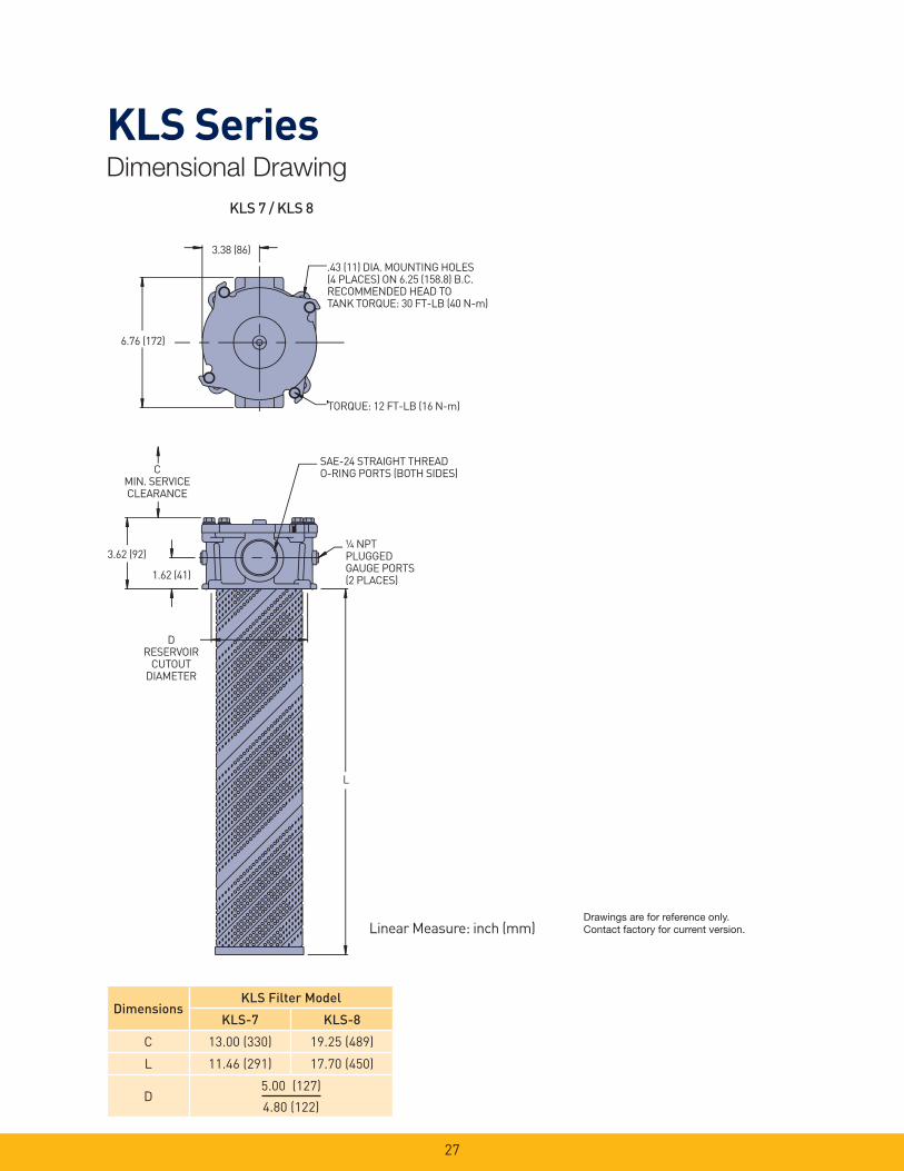
KLS SeriesDimensional Drawing
TORQUE: 12 FT-LB (16 N-m)
3.38 (86)
.43 (11) DIA. MOUNTING HOLES(4 PLACES) ON 6.25 (158.8) B.C.RECOMMENDED HEAD TOTANK TORQUE: 30 FT-LB (40 N-m)
6.76 (172)
CMIN. SERVICECLEARANCE
SAE-24 STRAIGHT THREADO-RING PORTS (BOTH SIDES)
3.62 (92)
1.62 (41)
DRESERVOIR
CUTOUTDIAMETER
¼ NPTPLUGGEDGAUGE PORTS(2 PLACES)
L
KLS 7 / KLS 8
Linear Measure: inch (mm)
DimensionsKLS Filter Model
KLS-7 KLS-8
C 13.00 (330) 19.25 (489)
L 11.46 (291) 17.70 (450)
D5.00 (127)
4.80 (122)
Drawings are for reference only. Contact factory for current version.
28
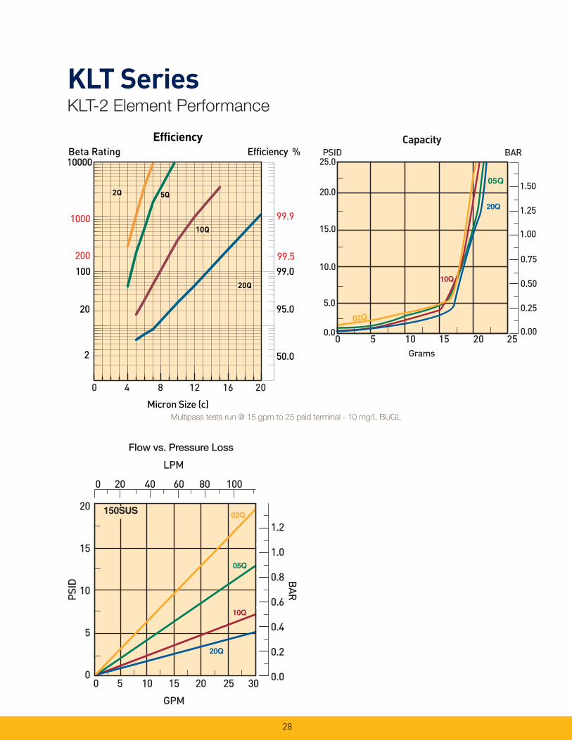
KLT Series KLT-2 Element Performance
Efficiency %Efficiency
Beta Rating
1000
10000
99.9
99.599.0100
200
20
2 50.0
95.0
Micron Size (c)
2Q
10Q
20Q
2Q
10Q
20Q
2Q
10Q
20Q
5Q5Q
0 4 8 12 16 20
Flow vs. Pressure Loss
Multipass tests run @ 15 gpm to 25 psid terminal - 10 mg/L BUGL
29
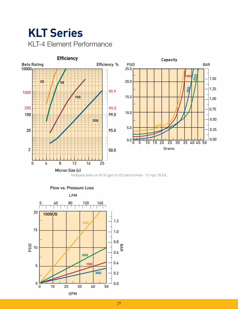
KLT SeriesKLT-4 Element Performance
Flow vs. Pressure Loss
Efficiency %Efficiency
Beta Rating
1000
10000
99.9
99.599.0100
200
20
2 50.0
95.0
Micron Size (c)
2Q
10Q
20Q
2Q
10Q
20Q
2Q
10Q
20Q
5Q5Q
0 4 8 12 16 20
Multipass tests run @ 30 gpm to 25 psid terminal - 10 mg/L BUGL
30
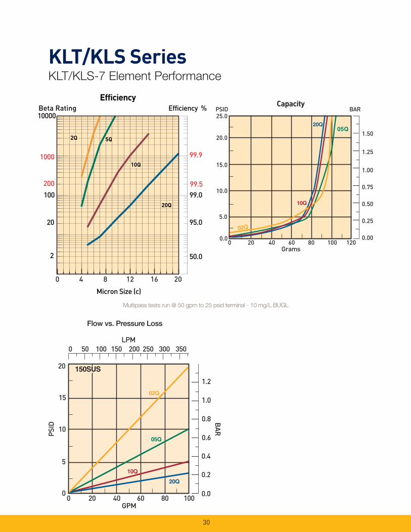
KLT/KLS Series KLT/KLS-7 Element Performance
Flow vs. Pressure Loss
Efficiency %Efficiency
Beta Rating
1000
10000
99.9
99.599.0100
200
20
2 50.0
95.0
Micron Size (c)
2Q
10Q
20Q
2Q
10Q
20Q
2Q
10Q
20Q
5Q5Q
0 4 8 12 16 20
Multipass tests run @ 50 gpm to 25 psid terminal - 10 mg/L BUGL

31
KLT/KLS SeriesKLT/KLS-8 Element Performance
Flow vs. Pressure Loss
Efficiency %Efficiency
Beta Rating
1000
10000
99.9
99.599.0100
200
20
2 50.0
95.0
Micron Size (c)
2Q
10Q
20Q
2Q
10Q
20Q
2Q
10Q
20Q
5Q5Q
0 4 8 12 16 20
Multipass tests run @ 70 gpm to 25 psid terminal - 10 mg/L BUGL

32
KLT and KLS SeriesOperating and Maintenance Instructions
Parts List
1
3
2
4
5
A. Mounting 1. Standard mounting.
a. Cut proper size hole in the top of the reservoir. b. Drill holes for studs within the proper bolt circle. c. Set the fi lter into the cutout hole and secure with
proper size bolts, nuts and lock washers. d. Torque nuts in accordance with drawing.
2. Mounting procedure using weld plate. a. Rough cut proper size hole in the top of reservoir. b. Weld the weld plate concentric to the rough cut
hole. c. Mount the fi lter onto the studs and secure with
nuts and lock washers. d. Torque nuts in accordance with drawing.
3. Utilize proper fi ttings.
B. Start-Up 1. Check for and eliminate leaks upon system start-up. 2. Check differential pressure indicator, if installed, to
monitor element condition.
C. Service 1. An element must be serviced when the indicator
indicates service is required.
NOTE: If the fi lter is not equipped with an indicator, the element should be serviced according to machine manufacturer’s instructions.
D. Servicing Dirty Element 1. Shut system down to assure that there is NO PRESSURE
OR FLOW into the fi lter housing. 2. Remove the fi lter cover. 3. Remove and discard the contaminated element cartridge.
E. Before Installing a New Element Cartridge 1. Clean the magnetic core with a lint-free cloth. 2. Check all seals and replace if necessary.
F. To Install a New Element Cartridge 1. Lubricate all seals. 2. Mount new fi lter cartridge. 3. Re-install the cover. 4. Torque the cover nuts per drawing.
Perform procedures B1 and B2 to ensure no leaks are present.
C.F. = Consult Factory
Index DescriptionPart
NumberQuantity
1 Cover Assembly (Includes Cover o-ring)
KLT2/KLT4 937049 1
KLT7/KLT8 937047 1
KLS7/KLS8 937048 1
2 Cover o-ring
KLT2/KLT4, Nitrile N72239 1
KLT2/KLT4, FKM V72239 1
KLT7/KLT8, Nitrile N72251 1
KLT7/KLT8, FKM V72251 1
KLS7/KLS8, Nitrile N72251 1
KLS7/KLS8, FKM V72251 1
3 Element (see How to Order page)
4 Filter Head (Includes gauge plugs & studs)
KLT2/KLT4 5841216 1
KLT7/KLT8 5841224 1
KLS7/KLS8 937318 1
5 Tank Gasket
KLT2/KLT4 108x98x5.5B 1
KLT7/KLT8 152x136x6B 1
KLS7/KLS8 937318 1
Not
ShownWeld Plate
KLT2/KLT4 300041 1
KLT7/KLT8 300042 1
Not
ShownPressure Switch NS-1C-19R/EL 1
Not
ShownPressure Gauge 936913 1

33
Select the desired symbol (in the correct position) to construct a model code. Example:
BOX 1 BOX 2 BOX 3 BOX 4 BOX 5 BOX 6 BOX 7 BOX 8
KLT 7 10Q B P G S24 1
BOX 1: Filter Series
Symbol Description
KLT Single port return-line
fi lter
KLS Dual port return-line fi lter
(-7 and -8 models only)
BOX 5: Indicator
Symbol Description
P No indicator; plugged
pressure port(s)
G Pressure gauge, 0-60 psig
S Pressure switch
BOX 4: Seals
Symbol Description
B Nitrile (NBR)
V Fluorocarbon
*NOTE: Nitrile tank gasket always supplied.
BOX 8: Options
Symbol Description
1 None
TP Weld plate (KLT only)
BOX 2: Filter Model
Symbol Description
2 30 GPM (115 l/m nominal fl ow)
4 50 GPM (190 l/m nominal fl ow)
7 100 GPM (380 l/m nominal fl ow)
8 120 GPM (455 l/m nominal fl ow)
BOX 3: Media Code
Symbol Description
02Q Microglass III, 2 micron
05Q Microglass III, 5 micron
10Q Microglass III, 10 micron
20Q Microglass III, 20 micron
WR Water Removal
BOX 6: Bypass
Symbol Pressure Setting
G 25 psid (1.7 bar)
KLT and KLS SeriesHow to Order
Global products as identifi ed are offered worldwide through all Parker locations and utilize a common ordering code.
Replacement Elements
Element Nitrile Fluorocarbon
Code 2 4 7 8 2 4 7 8
20Q 936967Q 936971Q 936975Q 936979Q 937269Q 937273Q 937277Q 937281Q
10Q 936966Q 936970Q 936974Q 936978Q 937268Q 937272Q 937276Q 937280Q
05Q 936965Q 936969Q 936973Q 936977Q 937267Q 937271Q 937275Q 937279Q
02Q 936964Q 936968Q 936972Q 936976Q 937266Q 937270Q 937274Q 937278Q
WR 937258 937259 937260 937261 C.F. C.F. C.F. C.F.
C.F. = Consult Factory
BOX 7: Ports
Symbol Description
KLT-2/4
S16 SAE-16 (1 5/16”-12)
KLT-7/8
S24 SAE-24 (1 7/8”-12)
KLS-7/8
S24 2 x SAE-24 (1 7/8”-12)
N24 2 x 1 1/2-NPT

Notes
34
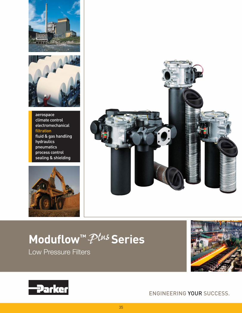
Modufl ow™ SeriesLow Pressure Filters
35
36
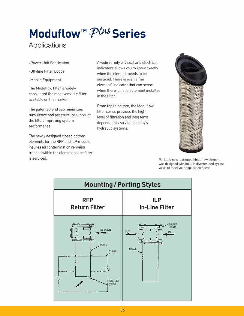
- Power Unit Fabrication
- Off-line Filter Loops
- Mobile Equipment
The Modufl ow fi lter is widely
considered the most versatile fi lter
available on the market.
The patented end cap minimizes
turbulence and pressure loss through
the fi lter, improving system
performance.
The newly designed closed bottom
elements for the RFP and ILP models
insures all contamination remains
trapped within the element as the fi lter
is serviced.
Mounting / Porting Styles
RFP
Return Filter
ILP
In-Line Filter
IN
BOWL
OUT
FILTERHEAD
RETURN
BOWL
TANK
OUTLETPORT
A wide variety of visual and electrical
indicators allows you to know exactly
when the element needs to be
serviced. There is even a “no
element” indicator that can sense
when there is not an element installed
in the fi lter.
From top to bottom, the Modufl ow
fi lter series provides the high
level of fi ltration and long term
dependability so vital to today’s
hydraulic systems.
Parker’s new patented Modufl ow element
was designed with built-in diverter and bypass
valve, to meet your application needs.
Applications
Modufl ow™ Series
37
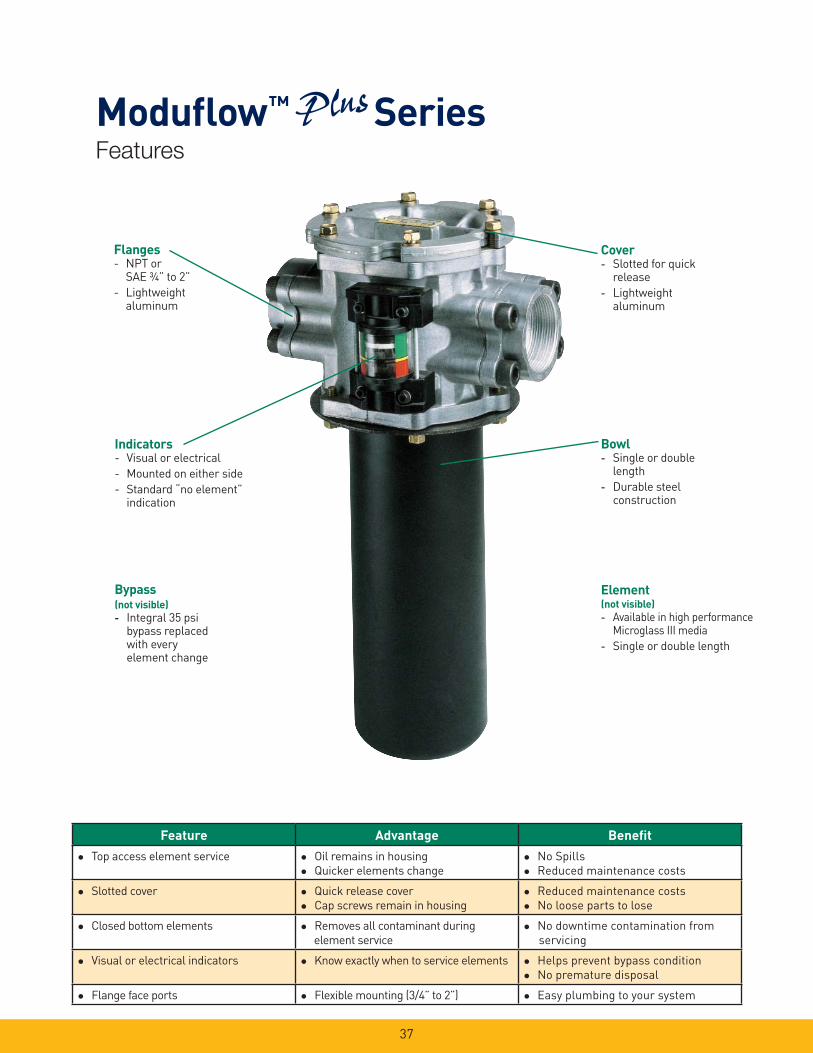
Modufl ow™ SeriesFeatures
Flanges- NPT or
SAE ¾” to 2”
- Lightweight aluminum
Bypass (not visible)
- Integral 35 psi bypass replaced
with every element change
Indicators- Visual or electrical
- Mounted on either side
- Standard “no element” indication
Cover- Slotted for quick
release
- Lightweight aluminum
Bowl- Single or double
length
- Durable steel construction
Element(not visible)
- Available in high performance Microglass III media
- Single or double length
Feature Advantage Benefi t
Top access element service Oil remains in housing
Quicker elements change
No Spills
Reduced maintenance costs
Slotted cover Quick release cover
Cap screws remain in housing
Reduced maintenance costs
No loose parts to lose
Closed bottom elements
Removes all contaminant during
element service
No downtime contamination from
servicing
Visual or electrical indicators Know exactly when to service elements Helps prevent bypass condition
No premature disposal
Flange face ports Flexible mounting (3/4” to 2”) Easy plumbing to your system
38
Efficiency %Efficiency
Beta Rating
1000
10000
99.9
99.599.0100
200
20
2 50.0
95.0
Micron Size (c)
2Q
10Q
20Q
2Q
10Q
20Q
2Q
10Q
20Q
5Q5Q
0 4 8 12 16 20
0 50 100 150 200 250 300 350
0 20 40 60 80 100
20
16
12
8
4
0
02Q
20Q
10Q
05Q
LPM
PSID
GPM
1.2
1.0
0.8
0.6
0.4
0.2
0.0
BAR
150SUS
Flow vs. Pressure Loss
CapacityBAR PSID
0
10
20
30
40
50
0.0
0.5
1.0
1.5
2.0
2.5
3.0
0 20 40 60 80 100 Capacity grams
2Q5Q10Q20Q
0 5 0 100 150 200 250 300 350
0 2 0 4 0 6 0 8 0 100
20
16
12
8
4
0
2” SAE flange
LPM
PSID
GPM
0.6
0.5
0.4
0.3
0.2
0.1
0.0
BAR
150SUS
Empty Housing
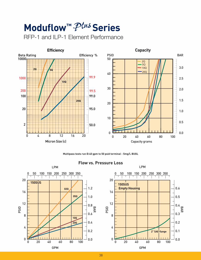
Multipass tests run @ 40 gpm to 50 psid terminal - 5mg/L BUGL
RFP-1 and ILP-1 Element Performance
Modufl ow™ Series

39
0 100 200 300 400 500
0 25 50 75 100 125 150
20
16
12
8
4
0
02Q
20Q10Q
05Q
LPM
PSID
GPM
1.2
1.0
0.8
0.6
0.4
0.2
0.0
BAR
150SUS
0 100 200 300 400 500
0 2 5 5 0 7 5 100 125 150
10
8
6
4
2
0
LPM
PSID
GPM
0.6
0.5
0.4
0.3
0.2
0.1
0.0
BAR
150SUS
2” SAE flange
Empty Housing
Flow vs. Pressure Loss
0.0
0.5
1.0
1.5
2.0
2.5
3.0
0
10
20
30
40
50
0 20 40 60 80 100 120 140 160
BARPSID
y
2Q5Q
10Q20Q
Efficiency %Efficiency
Beta Rating
1000
10000
99.9
99.599.0100
200
20
2 50.0
95.0
Micron Size (c)
2Q
10Q
20Q
2Q
10Q
20Q
2Q
10Q
20Q
5Q5Q
0 4 8 12 16 20
Multipass tests run @ 80 gpm to 50 psid terminal - 5mg/L BUGL
RFP-2 and ILP-2 Element Performance
Modufl ow™ Series
Capacity
Capacity grams

40
Pressure Ratings:
Maximum Allowable Operating Pressure (MAOP): 200 psi (13.8 bar)
Design Safety Factor: 2:1
Rated Fatigue Pressure: 150 psi (10.3 bar)
Element Burst Rating: 70 psid (4.8 bar)
Filter Materials: Head, Cover, Flanges: die cast aluminumBowl: steel
Operating Temperatures:Nitrile: -40°F to 225°F (-40°C to 107°C)Fluorocarbon: -15°F to 275°F (-26°C to 135°C)
Weight (approximate):Single: 20 lbs. (9.1 kg)Double: 25 lbs. (11.3 kg)
Indicators:Visual (optional)Electrical (optional) 15A @ 250VAC / .5A @ 125 VDCElectrical (“D” option) 5A @ 250VAC / 3A @ 28 VDC
Color Coding: White (normally closed)Red (normally open)Black (common)
168.06.6
A
OPTIONALTANK FLANGE
(99 OPTION) RFP-1 OUTLET 4 1” HOLES
2-11½” NPTFOPTIONALFITTING
69.9
2.75
D
RFP OUTLET
BCOPTIONAL MOUNTING BRACKET
78.73.1
MINIMUM ELEMENT REMOVAL CLEARANCE
345.913.62
482.619.00
Single:
Double:
168.0
6.7
108.5
4.27
196.3
7.7
OPTIONAL 3-PINMALE RECEPTACLEILP OUTLET
OPTIONAL PORT FLANGE
77.83.062
38.91.53
42.91.68
30.21.19 12.7
0.50
21.3
228.69.0
IL & RF INLET
Linear Measure: millimeterinch
Dimensions:mminch
Model A B C D
RFP-1 without
optional 2” fi tting
65.0
2.56
330.2
13.0_ 110.0
4.3
ILP-1 65.0
2.56
330.2
13.0
N/A 110.0
4.3
RFP-1 with
optional 2” fi tting
68.3
2.69_ 383.4
15.07
114.0
4.5
RFP-2 68.3
2.69
617.5
24.31
623.8
24.56
114.0
4.5
ILP-2 68.3
2.69
617.5
24.31
N/A 114.0
4.5
Specifi cations: RFP, ILP
Modufl ow™ Series
Drawings are for reference only. Contact factory for current version.
41
479.318.87
30.2
1.19
OPTIONALFLANGE
345.9
13.62
INLET
OUTLET
AIR BLEED EACH FILTER
177.87.00
402.815.86
OPTIONAL MECHANICAL INDICATOR
SINGLE
DOUBLE
¼-18 NPTDRAIN VENT
CONNECT TO TANK 173.0
6.81
½-13 SHCSTORQUE
32-38 FT-LB
110.54.35
79.03.11
116.84.60
76.2
617.524.31
330.213.0
3.00
25
20
15
10
5
1.75
1.5
1.25
0.75
0.5
0.25
0
1
FLOW LP MGPM
BAR
PSID
DIF
F. P
RESS
URE
0 10 20 30 40 50 60 70 80 90 100
0 25 50 75 100 125 375150 175 200 225 250 275 300 325
3000 SUS
200 SUS
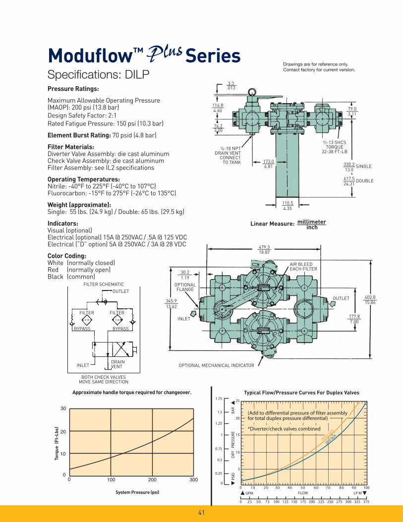
(Add to differential pressure of filter assembly (Add to differential pressure of filter assembly for total duplex pressure differential) for total duplex pressure differential) *Diverter/check valves combined *Diverter/check valves combined
(Add to differential pressure of filter assembly for total duplex pressure differential) *Diverter/check valves combined
Typical Flow/Pressure Curves For Duplex ValvesApproximate handle torque required for changeover.
System Pressure (psi)
To
rqu
e
(Ft-
Lb
s)
30
20
10
100 200 3000
0
3.3.013
Linear Measure: millimeterinch
BOTH CHECK VALVESMOVE SAME DIRECTION
FILTER SCHEMATIC
DRAIN VENT
BYPASS BYPASS
FILTERFILTER
OUTLET
INLET
Specifi cations: DILP
Modufl ow™ SeriesDrawings are for reference only. Contact factory for current version.
Pressure Ratings:
Maximum Allowable Operating Pressure (MAOP): 200 psi (13.8 bar)
Design Safety Factor: 2:1
Rated Fatigue Pressure: 150 psi (10.3 bar)
Element Burst Rating: 70 psid (4.8 bar)
Filter Materials: Diverter Valve Assembly: die cast aluminumCheck Valve Assembly: die cast aluminumFilter Assembly: see IL2 specifi cations
Operating Temperatures:Nitrile: -40°F to 225°F (-40°C to 107°C)Fluorocarbon: -15°F to 275°F (-26°C to 135°C)
Weight (approximate):Single: 55 lbs. (24.9 kg) / Double: 65 lbs. (29.5 kg)
Indicators:Visual (optional)Electrical (optional) 15A @ 250VAC / .5A @ 125 VDCElectrical (“D” option) 5A @ 250VAC / 3A @ 28 VDC
Color Coding: White (normally closed)Red (normally open)Black (common)

42
RFPSINGLE ELEMENT
452.1
17.8
RFPDOUBLE ELEMENT
688.3
27.1
MAX. O.D.OVER WELD
117.1
4.61(RFP & DOUBLE LENGTH)
3.0
2.5
2.0
1.5
1.0
0.5
0.0
Flow (GPM)
Pre
ssur
e Lo
ss (p
sid)
Check Valve Flow/Pressure Drop
0 10 20 30 40 50 60 70 80 90 100
*Check valve pressure drop must be added to assembly pressure drop to get total *Check valve pressure drop must be added to assembly pressure drop to get total
Linear Measure: millimeterinch
Specifi cations
Modufl ow™ Series
Drawings are for reference only. Contact factory for current version.
For return line applications (RFP), the fl uid
returning to the reservoir holds the check valve
open. When the system is shut down, the check
valve closes automatically.
43
38B6
0.7
0.6
0.5
0.4
0.3
0.2
0.1
0
10
8
6
4
2
00 5025 75 100 125 150 175 200 225
(PSI
)D
IFF.
PRE
SS.
(BA
R)
(GPM) INLET FLOW (LPM)
0 450 525 600 675
TYPICAL FLOW/PRESSURE CURVES FOR MODEL MM
750 825 900
250
37575 150 225 300
200
SUS
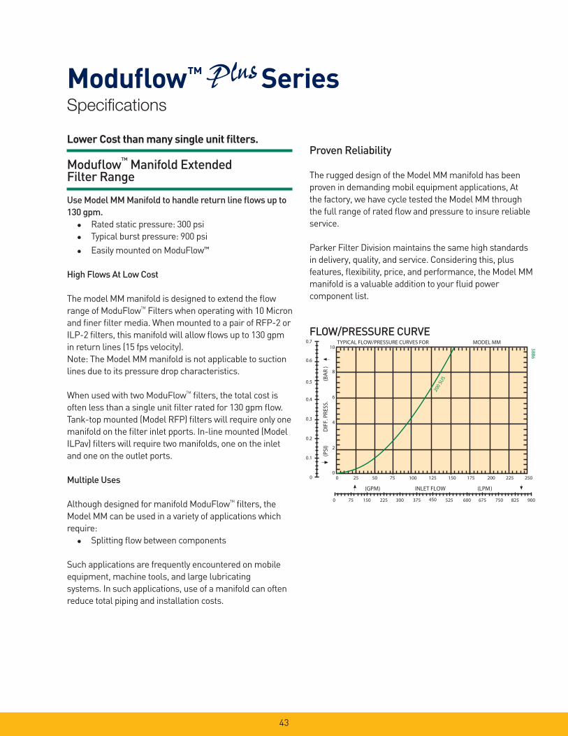
Lower Cost than many single unit fi lters.
Modufl ow™ Manifold Extended Filter Range
Use Model MM Manifold to handle return line fl ows up to 130 gpm. Rated static pressure: 300 psi
Typical burst pressure: 900 psi
Easily mounted on ModuFlow™
High Flows At Low Cost
The model MM manifold is designed to extend the fl ow
range of ModuFlowTM
Filters when operating with 10 Micron
and fi ner fi lter media. When mounted to a pair of RFP-2 or
ILP-2 fi lters, this manifold will allow fl ows up to 130 gpm
in return lines (15 fps velocity).
Note: The Model MM manifold is not applicable to suction
lines due to its pressure drop characteristics.
When used with two ModuFlowTM
fi lters, the total cost is
often less than a single unit fi lter rated for 130 gpm fl ow.
Tank-top mounted (Model RFP) fi lters will require only one
manifold on the fi lter inlet pports. In-line mounted (Model
ILPav) fi lters will require two manifolds, one on the inlet
and one on the outlet ports.
Multiple Uses
Although designed for manifold ModuFlowTM
fi lters, the
Model MM can be used in a variety of applications which
require:
Splitting fl ow between components
Such applications are frequently encountered on mobile
equipment, machine tools, and large lubricating
systems. In such applications, use of a manifold can often
reduce total piping and installation costs.
Proven Reliability
The rugged design of the Model MM manifold has been
proven in demanding mobil equipment applications, At
the factory, we have cycle tested the Model MM through
the full range of rated fl ow and pressure to insure reliable
service.
Parker Filter Division maintains the same high standards
in delivery, quality, and service. Considering this, plus
features, fl exibility, price, and performance, the Model MM
manifold is a valuable addition to your fl uid power
component list.
FLOW/PRESSURE CURVE
Specifi cations
Modufl ow™ Series
44
Specifi cations
Modufl ow™ Series
155.6mm 6.125
88.9mm 3.50
12.7mm .50 177.8mm
7.00 88.9mm 3.50
66.8mm 2.63
66.8mm 2.63
77.8mm 3.062 42.9mm
1.688
(TORQUE SCREWS TO 32-38 FT-LBS)
C C
273.8mm 10.78
42.9mm 1.688
77.8mm 3.062
(TORQUE SCREWS TO 32-38 FT-LBS)
VIEW AT C-C
STANDARD OUTLET, 2 PLS 2-0 SAE 4-BOLT FLANGE WITH 2-228 O-RING GROOVE
To one decimal place: To two decimal places: To three decimal places: Linear Measure:
TOLERANCES 3.0mm
0.12
0.8mm 0.03
0.4mm 0.015
Millimeter Inch
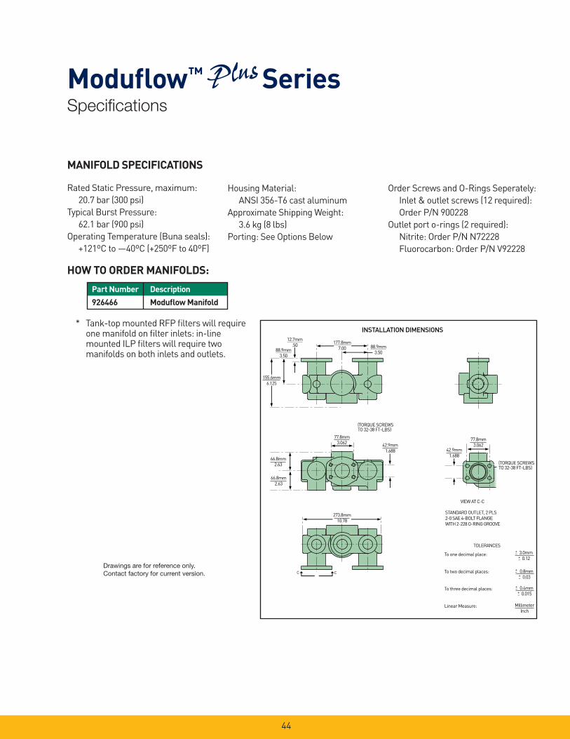
INSTALLATION DIMENSIONS
HOW TO ORDER MANIFOLDS:
MANIFOLD SPECIFICATIONS
Rated Static Pressure, maximum:
20.7 bar (300 psi)
Typical Burst Pressure:
62.1 bar (900 psi)
Operating Temperature (Buna seals):
+121ºC to —40ºC (+250ºF to 40ºF)
Housing Material:
ANSI 356-T6 cast aluminum
Approximate Shipping Weight:
3.6 kg (8 lbs)
Porting: See Options Below
Order Screws and O-Rings Seperately:
Inlet & outlet screws (12 required):
Order P/N 900228
Outlet port o-rings (2 required):
Nitrite: Order P/N N72228
Fluorocarbon: Order P/N V92228
* Tank-top mounted RFP fi lters will require one manifold on fi lter inlets: in-line mounted ILP fi lters will require two manifolds on both inlets and outlets.
Part Number Description
926466 Modufl ow Manifold
Drawings are for reference only. Contact factory for current version.
45
Accessories
Modufl ow™ Series
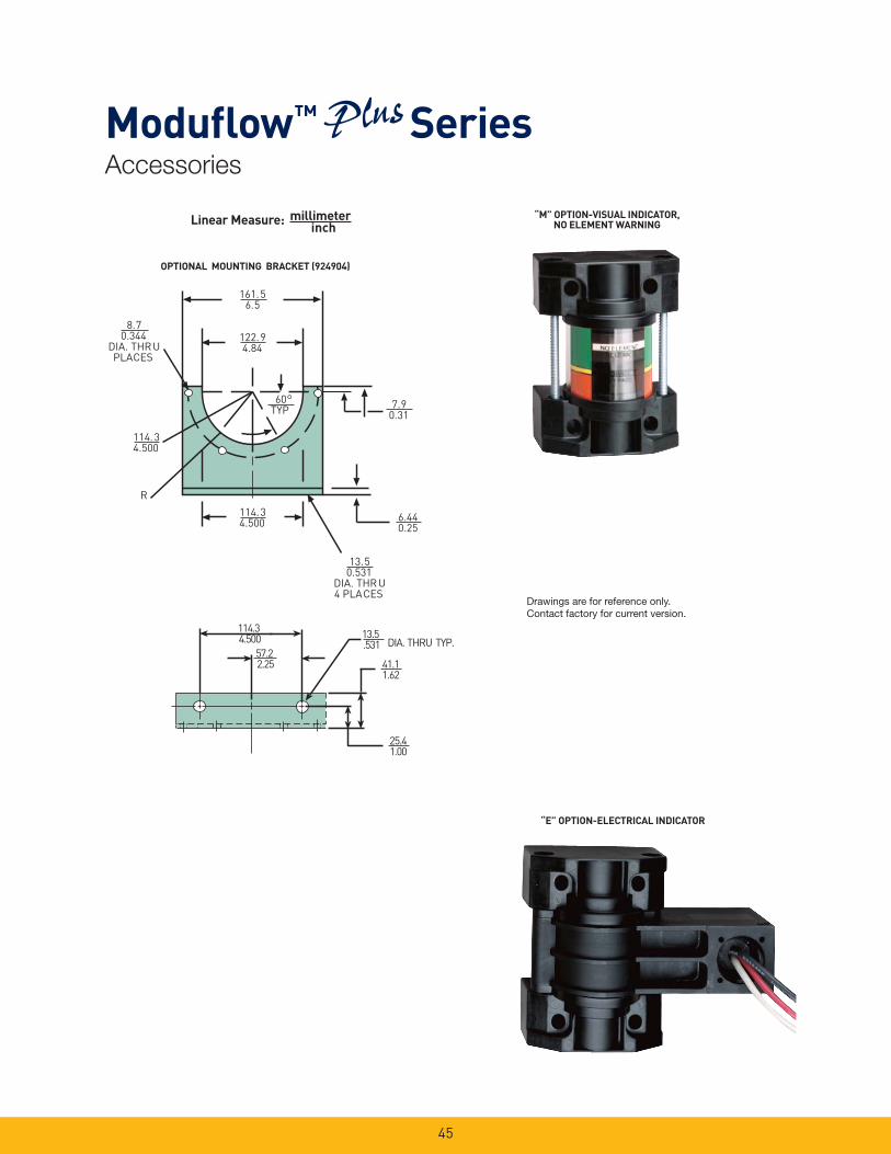
OPTIONAL MOUNTING BRACKET (924904)
Linear Measure: millimeterinch
122.94.84
161.56.5
114.34.500
13.50.531
DIA. THRU4 PLACES
114.34.500
R
60TYP 7.9
0.31
8.70.344
DIA. THRUPLACES
6.440.25
114.3 4.500
25.41.00
57.2 2.25
13.5 .531
41.11.62
DIA. THRU TYP.
“M” OPTION-VISUAL INDICATOR, NO ELEMENT WARNING
“E” OPTION-ELECTRICAL INDICATOR
Drawings are for reference only. Contact factory for current version.
46
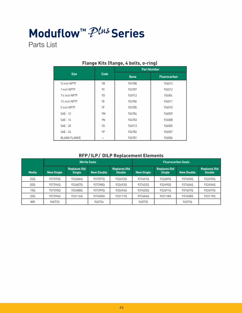
RFP / ILP / DILP Replacement Elements
Flange Kits (fl ange, 4 bolts, o-ring)
Size CodeBuna Fluorocarbon
¾ inch NPTF YB 924788 926013
1 inch NPTF YC 924787 926012
1¼ inch NPTF YD 924912 926004
1½ inch NPTF YE 924786 926011
2 inch NPTF YF 924785 926010
SAE - 12 YM 924784 926009
SAE - 16 YN 924783 926008
SAE - 20 YO 924913 926005
SAE - 24 YP 924782 926007
BLANK FLANGE — 924781 926006
Part Number
Media New Single
Replaces Old
Single New Double
Replaces Old
Double New Single
Replaces Old
Single New Double
Replaces Old
Double
02Q 937393Q 932686Q 937397Q 932692Q 937401Q 932689Q 937405Q 932695Q
05Q 937394Q 932687Q 937398Q 932693Q 937402Q 932690Q 937406Q 932696Q
10Q 937395Q 932688Q 937399Q 932694Q 937403Q 932691Q 937407Q 932697Q
20Q 937396Q 933116Q 937400Q 933117Q 937404Q 933118Q 937408Q 933119Q
WR 940733 940734 940735 940736
Nitrile Seals Fluorocarbon Seals
Parts List
Modufl ow™ Series
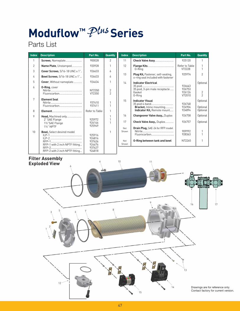
47
6
4 10 11
35
21
6 78
9
12
15
14
13
Filter AssemblyExploded View
16 17
Parts List
Modufl ow™ Series
Index Description Part No. Quantity
11 Check Valve Assy. ......................... 925120 1
12 Flange Kits..................................... O-Ring
Refer to TableV72228
11
13 Plug Kit, Fastener, self-sealing, o-ring seal included with fastener
925974 2
14 Indicator Electrical35 psid.............................................35 psid, 3-pin male receptacle.....GasketO-Ring
926643926753926126V72010
Optional
22
15 Indicator Visual35 psid 4-band...............................
Bracket, Inline mounting...........Indicator Kit, Remote mount.....
926748924904924894
Optional
OptionalOptional
16
17
Not
Shown
Not
Shown
Changeover Valve Assy., Duplex
Check Valve Assy., Duplex............
Drain Plug, SAE-24 for RFP modelNitrile............................................Fluorocarbon................................
O-Ring between tank and bowl
926758
926757
909992928363
N72265
Optional
Optional
11
1
Index Description Part No. Quantity
1 Screws, Nameplate....................... 900028 2
2 Name Plate, Unstamped............... 920928 1
3 Cover Screws, 5/16-18 UNC x 1”.. 926633 6
4 Bowl Screws, 5/16-18 UNC x 1”... 926633 6
5 Cover, Without nameplate............ 924634 1
6 O-Ring, coverNitrile............................................Fluorocarbon................................
N72350V72350
22
7 Element SealNitrile............................................Fluorocarbon................................
937410937411
11
8 Element.......................................... Refer to Table 1
9 Head, Machined only..................... 2” SAE Flange
1½”SAE Flange
1½” NPTF
925972926146925949
111
10 Bowl, Select desired model ILP-1.............................................ILP-2.............................................RFP-1............................................RFP-1 with 2 inch NPTF fi tting...RFP-2............................................RFP-2 with 2 inch NPTF fi tting...
925916924816937626924676937627924818
1
Drawings are for reference only. Contact factory for current version.
48
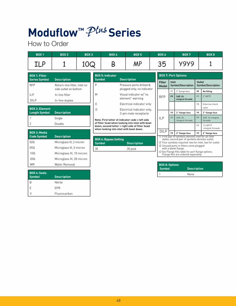
1) First pair of symbols denotes inlet for all fi lter styles; second pair of symbols denotes outlet.
2) Four symbols required: two for inlet, two for outlet.
3) Unused ports in fi lters come plugged with a blank fl ange.
4) See Flange Kits table for port fl ange options. Flange Kits are ordered separately.
BOX 1 BOX 2 BOX 3 BOX 4 BOX 5 BOX 6 BOX 7 BOX 8
ILP 1 10Q B MP 35 Y9Y9 1BOX 1: Filter
Series Symbol Description
RFP Return-line fi lter, inlet on
side outlet on bottom
ILP In-line fi lter
DILP In-line duplex
Filter
Model
Y9 2” fl ange face 99 No fi tting
RFP P9 SAE-24
integral threads
F9 2” NPTF
F8 External check
valve
Y9 2” fl ange face Y9 2” fl ange face
ILP P9 SAE-24
integral threads
P9 SAE-24 integral
threads
E9 1½ NPTF
integral threads
Y9 2” fl ange face Y9 2” fl ange face
BOX 7: Port Options
Inlet
Symbol/Description
Outlet
Symbol/Description
DILP
Note: First letter of indicator code = left side
of fi lter head when looking into inlet with bowl
down; second letter = right side of fi lter head
when looking into inlet with bowl down.
BOX 2: Element
Length Symbol Description
1 Single
2 Double
BOX 3: Media
Code Symbol Description
02Q Microglass III, 2 micron
05Q Microglass III, 5 micron
10Q Microglass III, 10 micron
20Q Microglass III, 20 micron
WR Water Removal
BOX 4: Seals
Symbol Description
B Nitrile
E EPR
V Fluorocarbon
BOX 5: Indicator
Symbol Description
P Pressure ports drilled &
plugged only; no indicator
M Visual indicator w/”no
element” warning
E Electrical indicator only
D Electrical indicator only,
3-pin male receptacle
BOX 6: Bypass Setting
Symbol Description
35 35 psid
BOX 8: Options
Symbol Description
1 None
How to Order
Modufl ow™ Series

49
Bowl-less Design
INLET FLANGEKIT ACCESSORY
3.24 [82.4]
1.19 [30.2]
3.06 [77.8]
2.47 [62.7]3.18 [80.7]
2.47 [63.0]
INLET
FLANGE SEALP/N N72251(SIZE 2-251)
12.19 [309.6] TFP-121.46 [545.1] TFP-2
TANK MOUNTINGSURFACE
(.010” MIN. FLATNESS REQUIRED FOR SEAL)
4.70 [119.4]TANK HOLE RECOMMENDED(5.00 [127.0] MAX ALLOWED)
.50 [12.7] MININSTALLATIONCLEARANCE TANK BOTTOM
SURFACE
INLETCONFIGURATION:
2” SAE FLANGE FACE(REF. SAE J518 CODE 61)
WITH INTEGRALSAE-24 (1 7/8-12 UN-2B
THREAD)O-RING BOSS PORT(REF. SAE J1926/1)
6.62 [168.1]COVER
5/16-18 UNC HEX HEADCOVER SCREW
TORQUE TO 16-20 FT-LBS
BYPASSFLOW
.50
BOTTOM VIEW.415 DIA TANKMOUNT HOLES
4-TOTAL ON 6.750BOLT CIRCLE
Shorter port-to-port distance.Direct tank mount capability eliminates need foradaptor fl anges and bowl.Standard head incorporates 2” SAE fl angeface with integral SAE-24 port confi guration.Filter head and element 2-piece construction requiresno fi lter bowl.Patented element design with integral bypass valve andinside to out fl ow path.
Provides a smaller footprint and reduced weight.Aluminum die cast head reduces weight and direct tankmount fl ange reduces installation time and cost.Enables one common head to be used.Simplifi es ordering model code.Reduces assembly cost by 25%.
Ensures all contaminants remain captured during service.New bypass valve with each element ensures operationreliability.
Features Advantages
45°
Modufl ow™ TFP Series

50
BOX 1 BOX 2 BOX 3 BOX 4 BOX 5 BOX 6 BOX 7 BOX 8
TFP 1 10Q B MP 35 C32 1
Note: Two letters are required for the indicator
code (e.g. “MP”)
Symbol Description
1 Single
2 Double
Symbol Description
02Q Microglass III, 2 micron
05Q Microglass III, 5 micron
10Q Microglass III, 10 micron
20Q Microglass III, 20 micron
WR Water Removal
BOX 4: Seals
Symbol Description
B Nitrile
E EPR
V Fluorocarbon
BOX 5: Indicator
Symbol Description
P Pressure ports drilled &
plugged only; no indicator
M Visual indicator w/”no
element” warning
E Electrical indicator only
D Electrical indicator only,
3-pin male receptacle
BOX 6: Bypass
Symbol Description
35 35 (2.4 bar) psid
BOX 8: Options
Symbol Description
1 None
BOX 1: Series
Symbol Description
TFP Return-line fi lter
TFPW Return-line fi lter anodized
for HWHC fl uid
Box 2: Element Length
Box 3: Media Code
BOX 8: Ports
Symbol Description
C32 2” SAE fl ange face/SAE-
24 combination inlet port
Media
TFP-1
Media
TFP-2
Nitrile FluorocarbonEthylene
PropyleneNitrile Fluorocarbon
Ethylene
Propylene
02Q 937393Q 937401Q 937671Q 02Q 937397Q 937405Q 937675Q
05Q 937394Q 937402Q 937672Q 05Q 937398Q 937406Q 937676Q
10Q 937395Q 937403Q 937673Q 10Q 937399Q 937407Q 937677Q
20Q 937396Q 937404Q 937674Q 20Q 937400Q 937408Q 937678Q
WR 940733 940735 N/A WR 940734 940736 N/A
Replacement Elements
How to Order
Modufl ow™ TFP Series

RF7 SeriesLow Pressure Filters
51

52
RF7 SeriesApplications
Element Condition Indicator
- True pressure differential
- Know, at a glance, when to change the fi lter element
- Gauge also available
Diffuser Tube
- Disperses return fl ow below reservoir fl uid level
- Prevents fl uid aeration
- Closed bottom provides for even fl uid dispersal
- Prevents objects from falling into the reservoir during element servicing
Cartridge/Element Handle
- Easy to remove entire assembly for servicing
Cover Lock-Band with “T” Handle
- Easy access for servicing
- No loose parts to remove and handle
- No special tools required for removal
Two-Piece Construction(Head/Tube)
- Easy in-tank mounting
Bypass Filter Screen
- Prevents gross contamination from passing through the fi lter — even during bypass
- Mobile equipment
- Power unit fabricators
- Off-line fi lter loops
The Parker RF7 fi lter is designed
for those applications where
depend able, yet economical, return
line system protection is required. The
in-tank mounting design makes the
RF7 ideally suited for use by power
unit fabricators and mobile equipment
manufacturers...or anyone who views
equipment space at a premium, but
not at the expense of performance.
Bypass Valves
- Virtually zero leakage
- Multiple valves for high fl ow
Vent
- For variable displacementpump applications

53
RF7 SeriesElement Features
Gasket Ring Seal- Positive sealing for
optimum element effi ciency
Inside each Parker Filter...
a quality Parker Element
The important item in a fi lter assembly
is the element. It has to capture and hold
contaminants that can damage or stop a
machine...while at the same time
allowing the required fl ow of clean
fl uid so the machine can function
properly.
There are many ways to design and build
an element, and it’s easy to produce a
low cost element. However, cost is not a
good selection criteria... especially when
the risk is loss of critical performance.
For instance, consider wire mesh
reinforcement. Not all fi lter elements
have it. It’s used in Parker elements to
keep the pleats from collapsing or
bunching.
If pleats bunch, the effective surface area
of the element is reduced,
excessive pressure drop develops, and
the fi lter assembly may go into the
bypass mode. This condition wastes
energy and allows unfi ltered fl uid
fl ow back into the system, effectively
shortening fi lter life.
Protective Perforated Cylinder- Necessary for
inside-to-outside fl ow
- Prevents media“blow out”
Wire Reinforced Media(Not Visible)- Prevents pleat
bunching
- Helps prevent media migration
- Maintains media effi ciency
Engineered Element Design- The right combination of
pleat depth and number of pleats means lower pressure losses (longer life)
- Dirt holding capability is maximized for less frequent element change-out
Elements for Every Application- Standard Microglass III
media for long life and excellent system protection
- Economical cellulose elements also available
Features Advantage Benefi ts
• Tank mounted design. • Saves space and reduces hardware requirements.
• Easy to integrate into system design.
• Cover fi ll port. • Allows 100% fi ltration of all new system oil. • Eliminates contamination before it can cause problems.
• High fl ow capacity. • One fi lter may handle all return line fl ows. • Cost savings in fi lters and hardware.
• Broad range of fi lter media available – including water removal.
• Choose the proper medium for system parameters.
• Cost savings by avoiding both “over” and “under” fi ltration.
• Inside-to-outside fl ow through element with a closed bottom end cap.
• All contamination is trapped inside of element assembly.
• Contamination is not reintroduced into the system during replacement.
• Wire reinforced Microglass III elements. • Rugged construction stands up to abuse of cyclic fl ows without performance loss.
• Wire support reduces pleat bunching, keeps pressure drop consistent.
• The reliable fi ltration provided assures equipment protection, reduces downtime, maximizes element life, and allows the hydraulic system to operate properly.
• Multipass tested elements (per ANSI/NFPA T3.10.8.8 R1-1990 modifi ed for fi ne fi ltration).
• Filter performance backed by recognized and accepted laboratory test standards.
• Filters you select have consistent performance levels.
• Complete element performance data disclosure.
• All pertinent information is provided in an easy-to-compare format.
• Provides an easy guide to proper fi lter selection.
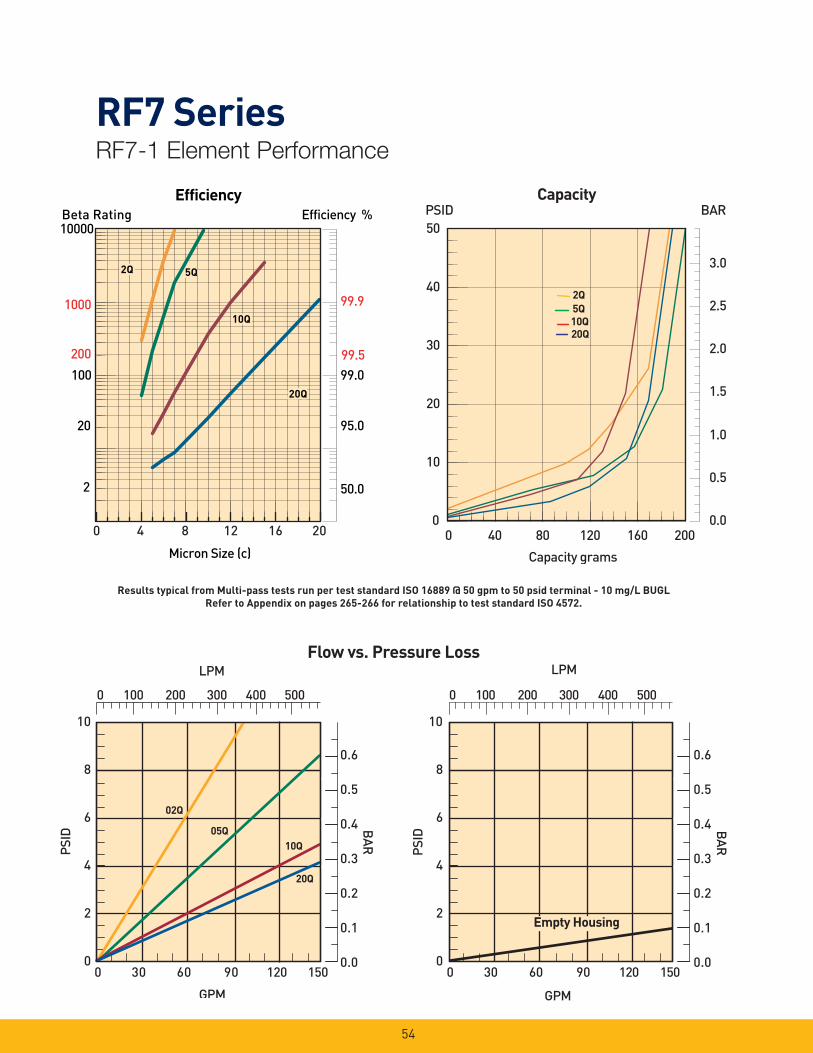
RF7 SeriesRF7-1 Element Performance
54
Efficiency %Efficiency
Beta Rating
1000
10000
99.9
99.599.0100
200
20
2 50.0
95.0
Micron Size (c)
2Q
10Q
20Q
2Q
10Q
20Q
2Q
10Q
20Q
5Q5Q
0 4 8 12 16 20
0 100 200 300 400 500
0 30 60 90 120 150
10
8
6
4
2
0
02Q
20Q
10Q05Q
LPM
PSID
GPM
0.6
0.5
0.4
0.3
0.2
0.1
0.0
BAR
0 100 200 300 400 500
0 30 60 90 120 150
10
8
6
4
2
0
LPM
PSID
GPM
0.6
0.5
0.4
0.3
0.2
0.1
0.0
BAR
Empty Housing
Flow vs. Pressure Loss
0.0
0.5
1.0
1.5
2.0
2.5
3.0
0 40 80 120 160 200
Capacity grams
0
10
20
30
40
50 PSID BAR
Capacity
2Q
5Q
20Q
10Q
Results typical from Multi-pass tests run per test standard ISO 16889 @ 50 gpm to 50 psid terminal - 10 mg/L BUGL
Refer to Appendix on pages 265-266 for relationship to test standard ISO 4572.
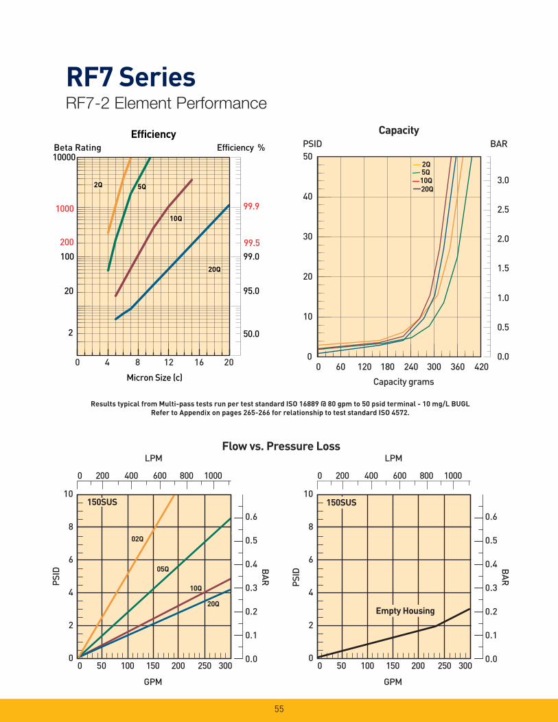
RF7 SeriesRF7-2 Element Performance
55
Efficiency %Efficiency
Beta Rating
1000
10000
99.9
99.599.0100
200
20
2 50.0
95.0
Micron Size (c)
2Q
10Q
20Q
2Q
10Q
20Q
2Q
10Q
20Q
5Q5Q
0 4 8 12 16 20
0 200 400 600 800 1000
0 50 100 150 200 250 300
10
8
6
4
2
0
02Q
20Q
10Q
05Q
LPM
PSID
GPM
0.6
0.5
0.4
0.3
0.2
0.1
0.0
BAR
150SUS
0 200 400 600 800 1000
0 50 100 150 200 250 300
10
8
6
4
2
0
LPM
PSID
GPM
0.6
0.5
0.4
0.3
0.2
0.1
0.0
BAR
Empty Housing
150SUS
Results typical from Multi-pass tests run per test standard ISO 16889 @ 80 gpm to 50 psid terminal - 10 mg/L BUGL
Refer to Appendix on pages 265-266 for relationship to test standard ISO 4572.
Flow vs. Pressure Loss
0.0
0.5
1.0
1.5
2.0
2.5
3.0
0
10
20
30
40
50
0 60 120 180 240 300 360 420
Capacity grams
PSID BAR Capacity
2Q
20Q
10Q5Q
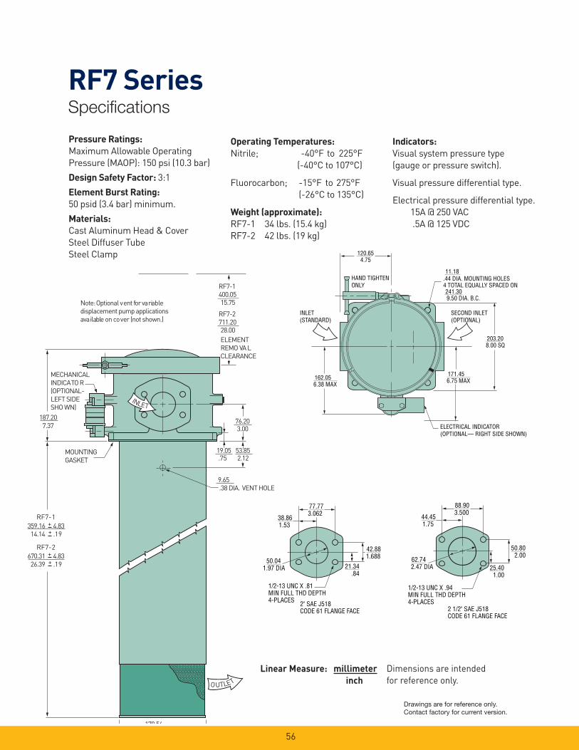
RF7 SeriesSpecifi cations
56
Pressure Ratings:
Maximum Allowable Operating
Pressure (MAOP): 150 psi (10.3 bar)
Design Safety Factor: 3:1
Element Burst Rating:
50 psid (3.4 bar) minimum.
Materials:
Cast Aluminum Head & Cover
Steel Diffuser Tube
Steel Clamp
Operating Temperatures:
Nitrile; -40°F to 225°F
(-40°C to 107°C)
Fluorocarbon; -15°F to 275°F
(-26°C to 135°C)
Weight (approximate):
RF7-1 34 lbs. (15.4 kg)
RF7-2 42 lbs. (19 kg)
Indicators:
Visual system pressure type
(gauge or pressure switch).
Visual pressure differential type.
Electrical pressure differential type.
15A @ 250 VAC
.5A @ 125 VDC
711.20
MOUNTING
GASKET
28.00
3.00
. 38 DIA. VENT HOLE
7.37
MECHANICAL
I NDICA TO R
(OPTIONAL-
LEFT SIDE
SHO WN) I N L E T
O U T L E T
187.20 76.20
.7 5 19.05
9.65
2.12 53.85
178 56
670.31 + 4.83 + .1 9 26.39
RF7- 2
359.16 + 4.83 + .1 9 14.14
RF7- 1
Note: Optional v ent f or va ri ab le
displacement pump applications
ava ila bl e on co v er (not sho wn. )
ELEMENT
REMO VA L
CLEARANCE
RF7-2
400.05 15.75
RF7-1
1/2-13 UNC X .81MIN FULL THD DEPTH4-PLACES 2" SAE J518
CODE 61 FLANGE FACE
3.06277.77
1.5338.86
1.97 DIA50.04
.8421.34
1.68842.88
1/2-13 UNC X .94MIN FULL THD DEPTH4-PLACES
3.50088.90
1.7544.45
2.47 DIA62.74
1.0025.40
2.0050.80
2 1/2" SAE J518CODE 61 FLANGE FACE
.44 DIA. MOUNTING HOLES4 TOTAL EQUALLY SPACED ON
HAND TIGHTENONLY
ELECTRICAL INDICATOR(OPTIONAL— RIGHT SIDE SHOWN)
4.75120.65
11.18
9.50 DIA. B.C.241.30
8.00 SQ203.20
6.75 MAX171.45
6.38 MAX162.05
INLET(STANDARD)
SECOND INLET(OPTIONAL)
Dimensions are intended
for reference only.
Linear Measure: millimeter
inch
Drawings are for reference only. Contact factory for current version.
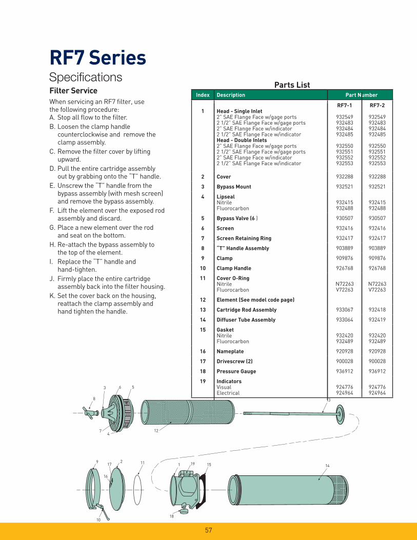
RF7 SeriesSpecifi cations
57
138
7
6 5
4
3
17
16
11
10
9 2151 19
18
14
12
Filter Service
When servicing an RF7 fi lter, use the following procedure:A. Stop all fl ow to the fi lter.
B. Loosen the clamp handle counterclockwise and remove the clamp assembly.
C. Remove the fi lter cover by lifting upward.
D. Pull the entire cartridge assembly out by grabbing onto the “T” handle.
E. Unscrew the “T” handle from the bypass assembly (with mesh screen) and remove the bypass assembly.
F. Lift the element over the exposed rod assembly and discard.
G. Place a new element over the rod and seat on the bottom.
H. Re-attach the bypass assembly to the top of the element.
I. Replace the “T” handle and hand-tighten.
J. Firmly place the entire cartridge assembly back into the fi lter housing.
K. Set the cover back on the housing, reattach the clamp assembly and hand tighten the handle.
Parts ListIndex Description
1 Head - Single Inlet2” SAE Flange Face w/gage ports2 1/2” SAE Flange Face w/gage ports2” SAE Flange Face w/indicator2 1/2” SAE Flange Face w/indicatorHead - Double Inlets2” SAE Flange Face w/gage ports2 1/2” SAE Flange Face w/gage ports2” SAE Flange Face w/indicator 2 1/2” SAE Flange Face w/indicator
RF7-1
932549932483932484932485
932550932551932552932553
RF7-2
932549932483932484932485
932550932551932552932553
2 Cover 932288 932288
3 Bypass Mount 932521 932521
4 LipsealNitrileFluorocarbon
932415932488
932415932488
5 Bypass Valve (6 ) 930507 930507
6 Screen 932416 932416
7 Screen Retaining Ring 932417 932417
8 “T” Handle Assembly 903889 903889
9 Clamp 909876 909876
10 Clamp Handle 926768 926768
11 Cover O-RingNitrileFluorocarbon
N72263V72263
N72263V72263
12 Element (See model code page)
13 Cartridge Rod Assembly 933067 932418
14 Diffuser Tube Assembly 933064 932419
15 GasketNitrileFluorocarbon
932420932489
932420932489
16 Nameplate 920928 920928
17 Drivescrew (2) 900028 900028
18 Pressure Gauge 936912 936912
19 IndicatorsVisualElectrical
924776924964
924776924964
Part Number
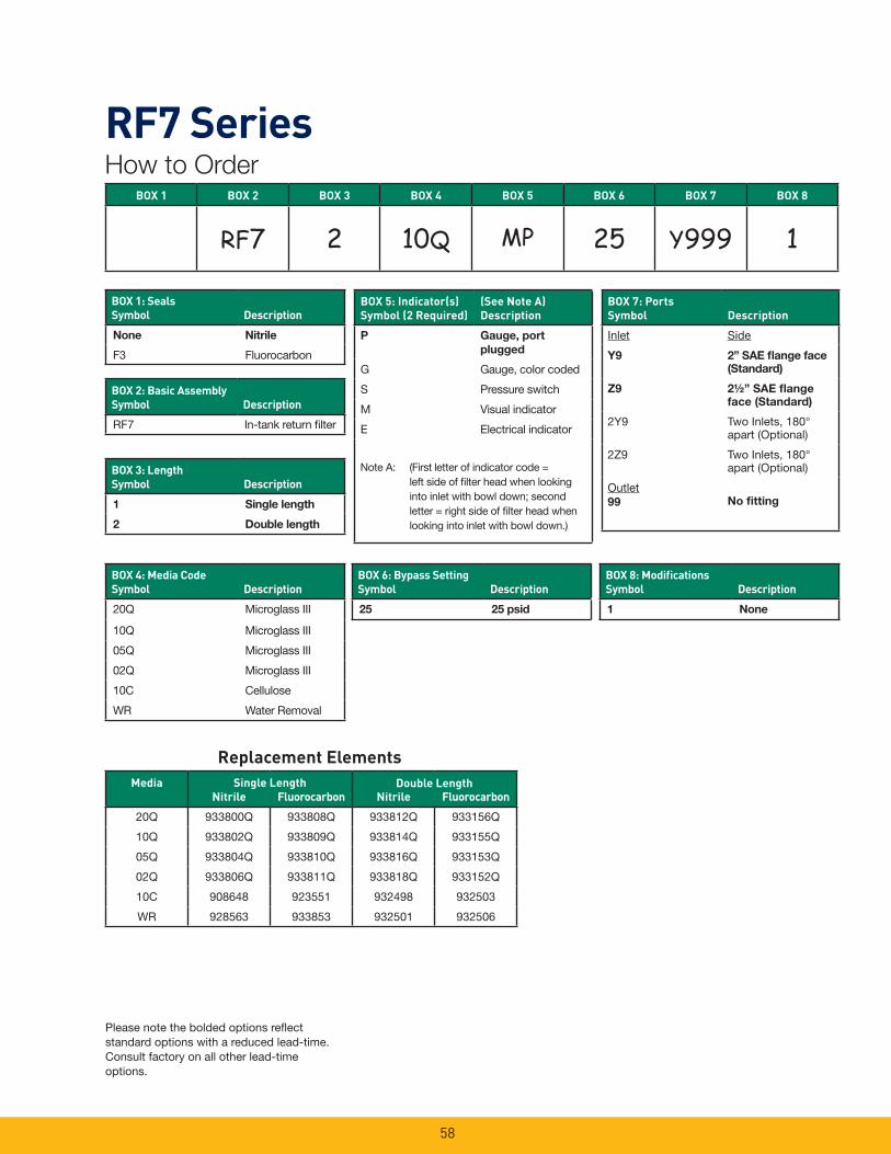
58
RF7 SeriesHow to Order
Replacement Elements
Please note the bolded options refl ect standard options with a reduced lead-time. Consult factory on all other lead-time options.
BOX 1 BOX 2 BOX 3 BOX 4 BOX 5 BOX 6 BOX 7 BOX 8
RF7 2 10Q MP 25 Y999 1
BOX 1: Seals
Symbol Description
None Nitrile
F3 Fluorocarbon
BOX 2: Basic Assembly
Symbol Description
RF7 In-tank return fi lter
BOX 3: Length
Symbol Description
1 Single length
2 Double length
BOX 5: Indicator(s)
Symbol (2 Required)
(See Note A)
Description
P Gauge, port
plugged
G Gauge, color coded
S Pressure switch
M Visual indicator
E Electrical indicator
Note A: (First letter of indicator code = left side of fi lter head when looking into inlet with bowl down; second letter = right side of fi lter head when looking into inlet with bowl down.)
BOX 7: Ports
Symbol Description
Inlet Side
Y9 2” SAE fl ange face
(Standard)
Z9 2½” SAE fl ange
face (Standard)
2Y9 Two Inlets, 180° apart (Optional)
2Z9 Two Inlets, 180° apart (Optional)
Outlet99 No fi tting
BOX 4: Media Code
Symbol Description
20Q Microglass III
10Q Microglass III
05Q Microglass III
02Q Microglass III
10C Cellulose
WR Water Removal
BOX 6: Bypass Setting
Symbol Description
25 25 psid
BOX 8: Modifi cations
Symbol Description
1 None
Media
Nitrile Fluorocarbon Nitrile Fluorocarbon
20Q 933800Q 933808Q 933812Q 933156Q
10Q 933802Q 933809Q 933814Q 933155Q
05Q 933804Q 933810Q 933816Q 933153Q
02Q 933806Q 933811Q 933818Q 933152Q
10C 908648 923551 932498 932503
WR 928563 933853 932501 932506
Single Length Double Length
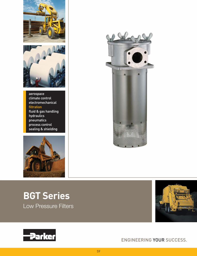
BGT SeriesLow Pressure Filters
59
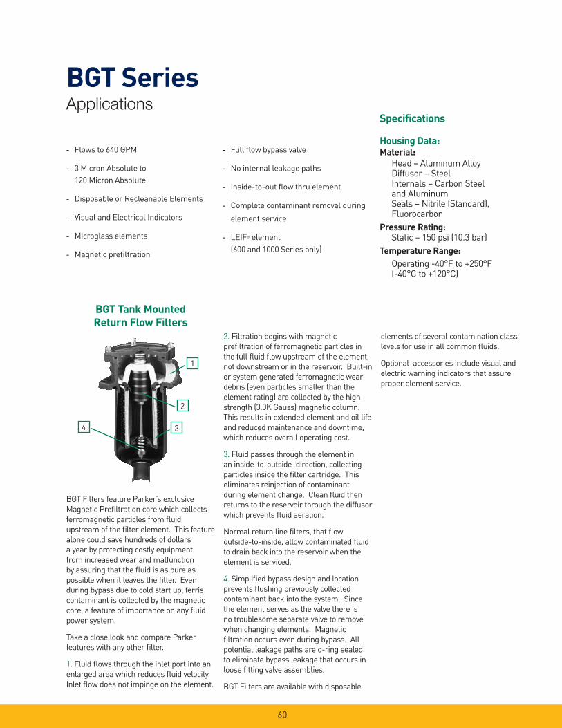
60
BGT SeriesApplications
Specifi cations
Housing Data:Material:
Head – Aluminum Alloy Diffusor – Steel Internals – Carbon Steel and Aluminum Seals – Nitrile (Standard), Fluorocarbon
Pressure Rating: Static – 150 psi (10.3 bar)
Temperature Range:
Operating -40°F to +250°F (-40°C to +120°C)
- Flows to 640 GPM
- 3 Micron Absolute to
120 Micron Absolute
- Disposable or Recleanable Elements
- Visual and Electrical Indicators
- Microglass elements
- Magnetic prefi ltration
- Full fl ow bypass valve
- No internal leakage paths
- Inside-to-out fl ow thru element
- Complete contaminant removal during
element service
- LEIF® element
(600 and 1000 Series only)
BGT Tank Mounted
Return Flow Filters
BGT Filters feature Parker’s exclusive
Magnetic Prefi ltration core which collects
ferromagnetic particles from fl uid
upstream of the fi lter element. This feature
alone could save hundreds of dollars
a year by protecting costly equipment
from increased wear and malfunction
by assuring that the fl uid is as pure as
possible when it leaves the fi lter. Even
during bypass due to cold start up, ferris
contaminant is collected by the magnetic
core, a feature of importance on any fl uid
power system.
Take a close look and compare Parker
features with any other fi lter.
1. Fluid fl ows through the inlet port into an
enlarged area which reduces fl uid velocity.
Inlet fl ow does not impinge on the element.
2. Filtration begins with magnetic
prefi ltration of ferromagnetic particles in
the full fl uid fl ow upstream of the element,
not downstream or in the reservoir. Built-in
or system generated ferromagnetic wear
debris (even particles smaller than the
element rating) are collected by the high
strength (3.0K Gauss) magnetic column.
This results in extended element and oil life
and reduced maintenance and downtime,
which reduces overall operating cost.
3. Fluid passes through the element in
an inside-to-outside direction, collecting
particles inside the fi lter cartridge. This
eliminates reinjection of contaminant
during element change. Clean fl uid then
returns to the reservoir through the diffusor
which prevents fl uid aeration.
Normal return line fi lters, that fl ow
outside-to-inside, allow contaminated fl uid
to drain back into the reservoir when the
element is serviced.
4. Simplifi ed bypass design and location
prevents fl ushing previously collected
contaminant back into the system. Since
the element serves as the valve there is
no troublesome separate valve to remove
when changing elements. Magnetic
fi ltration occurs even during bypass. All
potential leakage paths are o-ring sealed
to eliminate bypass leakage that occurs in
loose fi tting valve assemblies.
BGT Filters are available with disposable
elements of several contamination class
levels for use in all common fl uids.
Optional accessories include visual and
electric warning indicators that assure
proper element service.
4
1
2
3
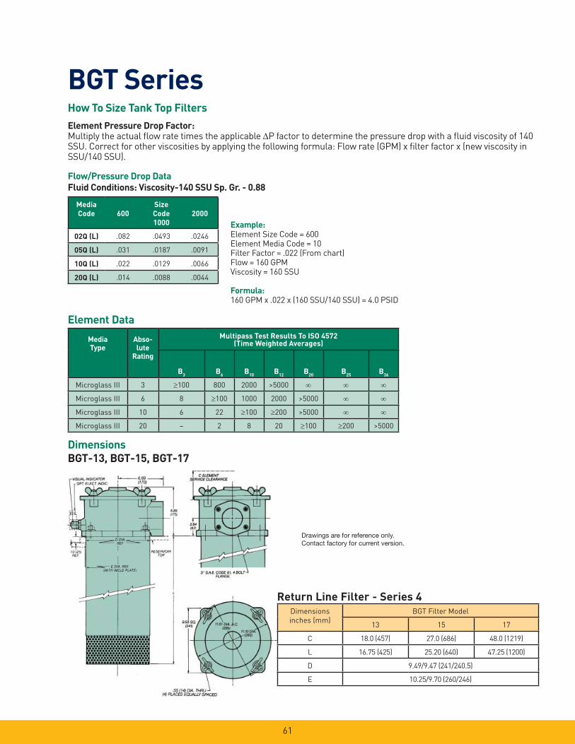
61
BGT Series
Dimensions
BGT-13, BGT-15, BGT-17
Example:Element Size Code = 600Element Media Code = 10Filter Factor = .022 (From chart)Flow = 160 GPMViscosity = 160 SSU
Formula: 160 GPM x .022 x (160 SSU/140 SSU) = 4.0 PSID
How To Size Tank Top Filters
Element Pressure Drop Factor:Multiply the actual fl ow rate times the applicable P factor to determine the pressure drop with a fl uid viscosity of 140 SSU. Correct for other viscosities by applying the following formula: Flow rate (GPM) x fi lter factor x (new viscosity in SSU/140 SSU).
Flow/Pressure Drop Data
Fluid Conditions: Viscosity-140 SSU Sp. Gr. - 0.88
Element Data
Media
Code 600
Size
Code
1000
2000
02Q (L) .082 .0493 .0246
05Q (L) .031 .0187 .0091
10Q (L) .022 .0129 .0066
20Q (L) .014 .0088 .0044
Media
Type
Abso-
lute
Rating
Multipass Test Results To ISO 4572(Time Weighted Averages)
B3
B6
B10
B12
B20
B25
B36
Microglass III 3 100 800 2000 >5000
Microglass III 6 8 100 1000 2000 >5000
Microglass III 10 6 22 100 200 >5000
Microglass III 20 – 2 8 20 100 200 >5000
Return Line Filter - Series 4
Dimensions
inches (mm)
BGT Filter Model
13 15 17
C 18.0 (457) 27.0 (686) 48.0 (1219)
L 16.75 (425) 25.20 (640) 47.25 (1200)
D 9.49/9.47 (241/240.5)
E 10.25/9.70 (260/246)
Drawings are for reference only. Contact factory for current version.
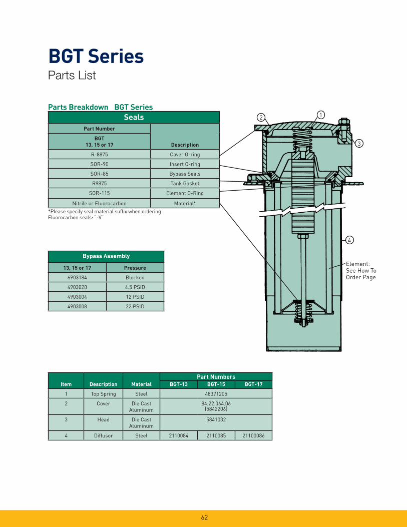
62
BGT SeriesParts List
Parts Breakdown BGT Series
*Please specify seal material suffi x when ordering Fluorocarbon seals: “-V”
2 1
3
4
Element:See How To Order Page
Part Number
BGT
13, 15 or 17 Description
R-8875 Cover O-ring
SOR-90 Insert O-ring
SOR-85 Bypass Seals
R9875 Tank Gasket
SOR-115 Element O-Ring
Nitrile or Fluorocarbon Material*
Seals
13, 15 or 17 Pressure
6903184 Blocked
4903020 4.5 PSID
4903004 12 PSID
4903008 22 PSID
Bypass Assembly
Item Description Material BGT-13 BGT-15 BGT-17
1 Top Spring Steel 48371205
2 Cover Die Cast
Aluminum
84.22.064.06(5842206)
3 Head Die Cast
Aluminum
5841032
4 Diffusor Steel 2110084 2110085 21100086
Part Numbers
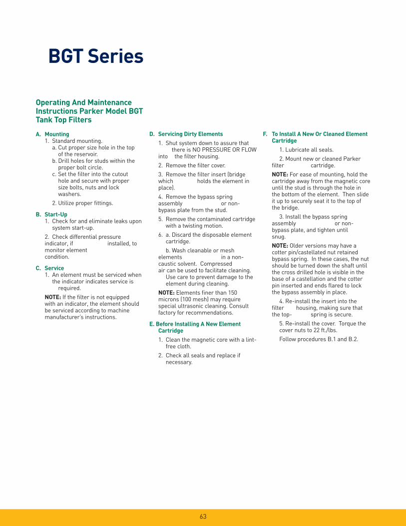
63
BGT Series
Operating And Maintenance Instructions Parker Model BGT Tank Top Filters
A. Mounting 1. Standard mounting. a. Cut proper size hole in the top
of the reservoir. b. Drill holes for studs within the
proper bolt circle. c. Set the fi lter into the cutout
hole and secure with proper size bolts, nuts and lock washers.
2. Utilize proper fi ttings.
B. Start-Up 1. Check for and eliminate leaks upon
system start-up.
2. Check differential pressure indicator, if installed, to monitor element condition.
C. Service 1. An element must be serviced when
the indicator indicates service is required.
NOTE: If the fi lter is not equipped with an indicator, the element should be serviced according to machine manufacturer’s instructions.
D. Servicing Dirty Elements
1. Shut system down to assure that there is NO PRESSURE OR FLOW into the fi lter housing.
2. Remove the fi lter cover.
3. Remove the fi lter insert (bridge which holds the element in place).
4. Remove the bypass spring assembly or non-bypass plate from the stud.
5. Remove the contaminated cartridge with a twisting motion.
6. a. Discard the disposable element cartridge.
b. Wash cleanable or mesh elements in a non-caustic solvent. Compressed air can be used to facilitate cleaning. Use care to prevent damage to the element during cleaning.
NOTE: Elements fi ner than 150 microns (100 mesh) may require special ultrasonic cleaning. Consult factory for recommendations.
E. Before Installing A New Element Cartridge
1. Clean the magnetic core with a lint- free cloth.
2. Check all seals and replace if necessary.
F. To Install A New Or Cleaned Element Cartridge
1. Lubricate all seals.
2. Mount new or cleaned Parker fi lter cartridge.
NOTE: For ease of mounting, hold the cartridge away from the magnetic core until the stud is through the hole in the bottom of the element. Then slide it up to securely seat it to the top of the bridge.
3. Install the bypass spring assembly or non-bypass plate, and tighten until snug.
NOTE: Older versions may have a cotter pin/castellated nut retained bypass spring. In these cases, the nut should be turned down the shaft until the cross drilled hole is visible in the base of a castellation and the cotter pin inserted and ends fl ared to lock the bypass assembly in place.
4. Re-install the insert into the fi lter housing, making sure that the top- spring is secure.
5. Re-install the cover. Torque the cover nuts to 22 ft./lbs.
Follow procedures B.1 and B.2.

64
BGT SeriesHow to Order
BOX 1 BOX 2 BOX 3 BOX 4 BOX 5 BOX 6 BOX 7 BOX 8
BGT 13 10QL B V E F48 1
BOX 1: Basic As-
sembly
Symbol
Description
BGT Return Filter
BOX 4: Seals
Symbol Description
B Nitrile
BOX 2: Housing
Length
Symbol
Description
13 4-600 L/min Return Filter (160
gpm)
15 4-1000 L/min Return Filter (265
gpm)
17 4-2000 L/min Return Filter (530
gpm)
BOX 3: Element
Media
Symbol
Description
02QL05QL10QL20QL
BTG13, 4-600 L/minLeif® Microglass III ElementLeif® Microglass III ElementLeif® Microglass III ElementLeif® Microglass III Element
02QL05QL10QL20QL
BTG15, 4-1000 L/minLeif® Microglass III ElementLeif® Microglass III ElementLeif® Microglass III ElementLeif® Microglass III Element
02Q05Q10Q20Q
BTG17, 4-2000 L/minMicroglass III ElementMicroglass III ElementMicroglass III ElementMicroglass III Element
BOX 5: Indicator
Symbol Description
P
VE
Plugged Indicator Port
Visual Differential IndicatorElectrical Differential Indicator
BOX 6: Bypass
Symbol Description
E 22 PSID Bypass (1,5 bar)
BOX 7: Ports
Symbol Description
F48 3” SAE Flange, Code 61
BOX 8: Options
Symbol Description
1 No Options

12CS/50CS SeriesCoreless Medium Pressure Filters
65

66
12CS/50CS SeriesApplications
Parker engineers have developed an innovative alternative to the age old spin-on style can. This new design provides all of the benefi ts of high effi ciency, long life Ecoglass III fi ltration, without the environmental impact.
The new environmentally-friendly 12CS and 50CS hydraulic fi lters feature a reusable bowl and a patented fi lter element constructed of reinforced polymer end caps, microglass media, and polymer pleat support. The element core is permanently attached as part of the fi lter bowl. When replaced, the element reduces costs, eliminates hot drain requirements, can be easily incinerated, and is better-suited for most landfi lls.
The 500 psi fi lters are rated up to 50 gpm, with premium Ecoglass III elements as standard offerings. The patented element design also prevents fi lter operation if the proper element is not in place.
Together we can…
Preserve the environment. Minimize waste and promote energy effi ciency.
Achieve worldwide fi ltration solutions. Build global confi dence.
Redefi ne new limits. Forge ahead with advanced technology.
Keep contamination under control. Reduce maintenance costs.
Enhance total system reliability. Focus on customer satisfaction.
Reach optimum potential. Drill to greater depths.
…engineer your success.
Typical Applications
• Mobile Ag
• Mobile Construction
• Material Handlers
• Aerial Lifts
• Pilot Lines
• Charge Pump Hydrostatic
Drives
• Industrial Power Units
• Machine Tools
• Joy Stick Controls
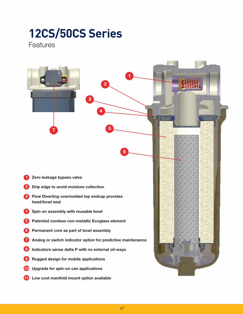
67
12CS/50CS SeriesFeatures
4
5
1
6
3
2
7
1 Zero leakage bypass valve
2 Drip edge to avoid moisture collection
3 Flow Diverting overmolded top endcap provides
head/bowl seal
Spin-on assembly with reusable bowl
Patented coreless non-metallic Ecoglass element
Permanent core as part of bowl assembly
Analog or switch indicator option for predictive maintenance
Indicators sense delta P with no external oil-ways
Rugged design for mobile applications
Upgrade for spin-on can applications
Low cost manifold mount option available
2
3
4
6
5
7
8
9
10
11

68
12CS/50CS SeriesThe Smart Alternative to Spin-on Cans!
Patented Filter Element
Provides head-to-bowl seal
Cannot operate without an element installed
Spin-on Assembly with
Reusable Bowl
Improved, cost effective design
Easy to maintainEasy to maintain
Application versatility
500 PSI Operating Pressure
Withstands pressure surges
an element installed
Spin-on Assembly with
Reusable Bowl
Improved, cost effective design
Ease-of-Service, environmentally friendly
Coreless Ecoglass Elements
Reduces disposal costs and environmental impact
Application versatility
No external oil-ways
Option for Differential
Pressure Sensing including
an Analog 0-5V Output
For predictive maintenance
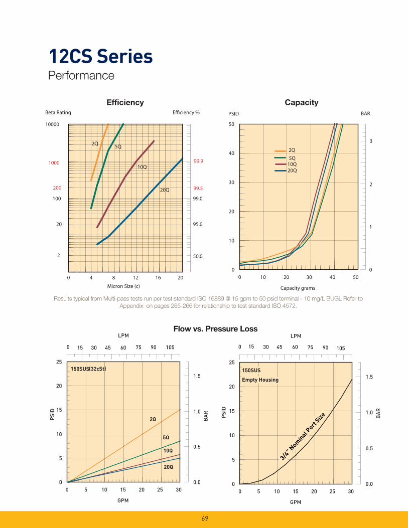
69
12CS Series Performance
Efficiency %Beta Rating
1000
10000
99.9
99.5
99.0100
200
20
2 50.0
95.0
0 4 8 12 16 20
Micron Size (c)
5Q
10Q
20Q
2Q
BARPSID
0
1
3
0
10
20
30
40
50
0 10 20 30 40 50
Capacity grams
5Q10Q20Q
2Q
2
BA
R
20Q
5Q
150SUS
10Q
0.0
0.5
1.0
1.5
0
LPM
0 5 10 15 20 25 30
GPM
0
5
10
15
20
25
PSI
D
2Q
15 30 45 60 75 90 105
(32cSt)
0
LPM
0 5 10 15 20 25 30
GPM
0.0
0.5
1.0
1.5B
AR
0
5
10
15
20
25
Empty Housing
150SUS
Empty Housing
150SUS
PSI
D
15 30 45 60 75 90 105
3/4”
Nom
inal P
ort S
ize
3/4”
Nom
inal P
ort S
ize
Effi ciency Capacity
Flow vs. Pressure Loss
Results typical from Multi-pass tests run per test standard ISO 16889 @ 15 gpm to 50 psid terminal - 10 mg/L BUGL Refer to
Appendix on pages 265-266 for relationship to test standard ISO 4572.

70
50CS SeriesPerformance
% ycneiciffEBeta Rating
1000
10000
99.9
99.5
99.0100
200
20
2 50.0
95.0
20Q
10Q
5Q2Q
0.0 5.0 10.0 15.0 20.0 25.0Micron Size (c)
RABPSID
2Q
10Q20Q
5Q
00 20 40 60 80 100
Capacity grams
0
10
20
30
40
50
1
2
3
10Q
2Q
5Q
20Q
150SUS (32 cSt)
0.0
0.5
1.0
1.5
BA
R
0
LPM
0 10 20 30 40 50 60
GPM
0
5
10
15
20
25
PS
ID
30 60 90 120 150 180 210 0
LPM
0.0
5.0
10.0
15.0
20.0
25.0
PS
ID
0 10 20 30 40 50 60
GPM
0.0
BA
REmpty Housing
1 1/4" Nominal Port Size
150SUS
1
0.5
1.5
30 90 120 150 180 21060
1"Nom
inal P
ort S
ize
1 1/2" Nominal Port Size
Effi ciency Capacity
Flow vs. Pressure Loss
Results typical from Multi-pass tests run per test standard ISO 16889 @ 30 gpm to 50 psid terminal - 10 mg/L BUGL.
Refer to Appendix on pages 265-266 for relationship to test standard ISO 4572.
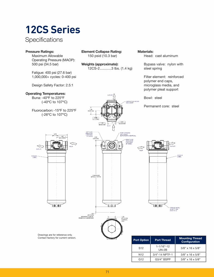
71
12CS SeriesSpecifi cations
Port Option Port ThreadMounting Thread
Confi guration
S121-1/16”-12
UN-2B3/8” x 16 x 5/8”
N12 3/4”-14 NPTF-1 3/8” x 16 x 5/8”
G12 G3/4” BSPP 3/8” x 16 x 5/8”
Drawings are for reference only. Contact factory for current version.
Element Collapse Rating:
150 psid (10.3 bar)
Weights (approximate):
12CS-2............3 lbs. (1.4 kg)
Materials:
Head: cast aluminum
Bypass valve: nylon with steel spring
Filter element: reinforced polymer end caps, microglass media, and polymer pleat support
Bowl: steel
Permanent core: steel
Pressure Ratings:
Maximum Allowable Operating Pressure (MAOP): 500 psi (34.5 bar)
Fatigue: 400 psi (27.6 bar) 1,000,000+ cycles: 0-400 psi
Design Safety Factor: 2.5:1
Operating Temperatures:
Buna: -40ºF to 225ºF (-40ºC to 107ºC)
Fluorocarbon: -15ºF to 225ºF (-26ºC to 107ºC)
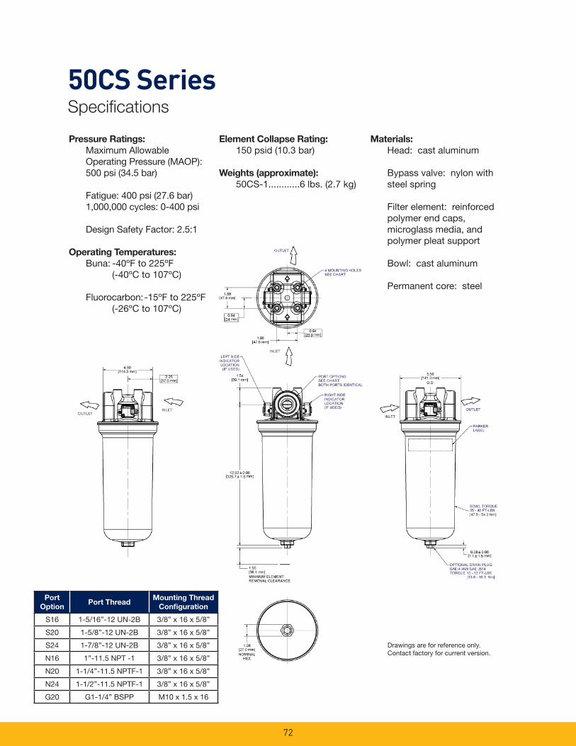
72
50CS SeriesSpecifi cations
Drawings are for reference only. Contact factory for current version.
Element Collapse Rating:
150 psid (10.3 bar)
Weights (approximate):
50CS-1............6 lbs. (2.7 kg)
Materials:
Head: cast aluminum
Bypass valve: nylon with steel spring
Filter element: reinforced polymer end caps, microglass media, and polymer pleat support
Bowl: cast aluminum
Permanent core: steel
Pressure Ratings:
Maximum Allowable Operating Pressure (MAOP): 500 psi (34.5 bar)
Fatigue: 400 psi (27.6 bar) 1,000,000 cycles: 0-400 psi
Design Safety Factor: 2.5:1
Operating Temperatures:
Buna: -40ºF to 225ºF (-40ºC to 107ºC)
Fluorocarbon: -15ºF to 225ºF (-26ºC to 107ºC)
Port
OptionPort Thread
Mounting Thread
Confi guration
S16 1-5/16”-12 UN-2B 3/8” x 16 x 5/8”
S20 1-5/8”-12 UN-2B 3/8” x 16 x 5/8”
S24 1-7/8”-12 UN-2B 3/8” x 16 x 5/8”
N16 1”-11.5 NPT -1 3/8” x 16 x 5/8”
N20 1-1/4”-11.5 NPTF-1 3/8” x 16 x 5/8”
N24 1-1/2”-11.5 NPTF-1 3/8” x 16 x 5/8”
G20 G1-1/4” BSPP M10 x 1.5 x 16
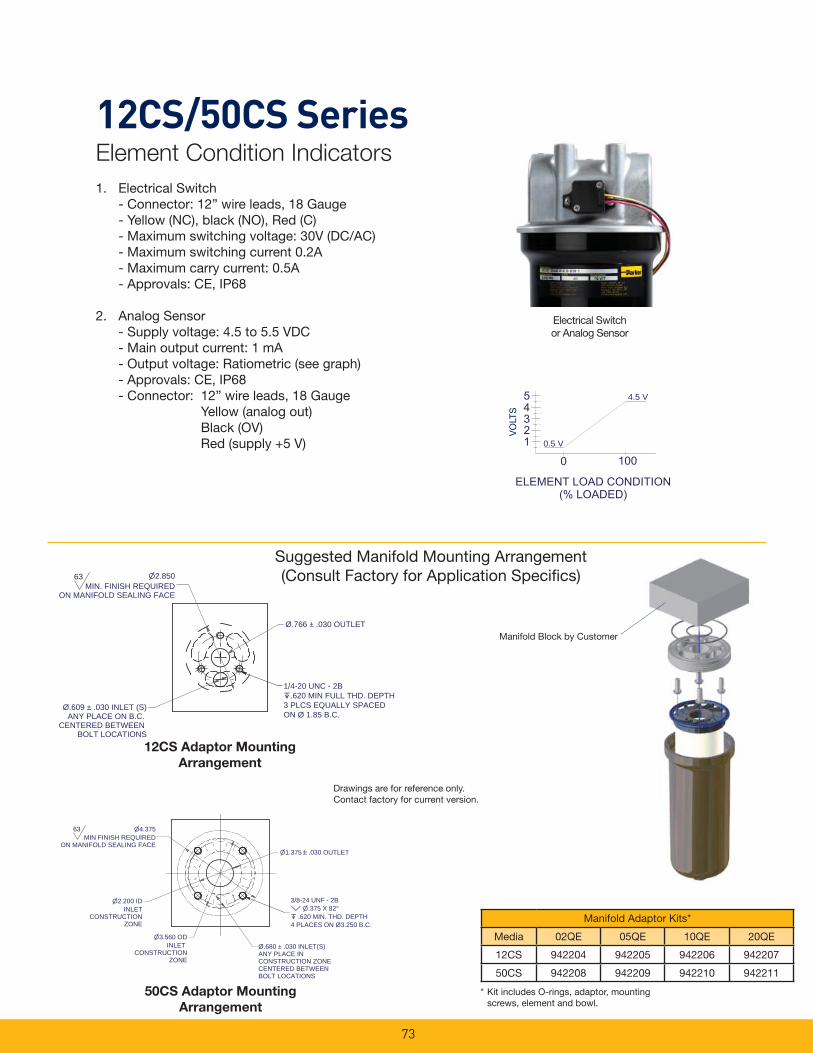
73
12CS/50CS SeriesElement Condition Indicators
Electrical Switchor Analog Sensor
1. Electrical Switch - Connector: 12” wire leads, 18 Gauge - Yellow (NC), black (NO), Red (C) - Maximum switching voltage: 30V (DC/AC) - Maximum switching current 0.2A - Maximum carry current: 0.5A - Approvals: CE, IP68
2. Analog Sensor - Supply voltage: 4.5 to 5.5 VDC - Main output current: 1 mA - Output voltage: Ratiometric (see graph) - Approvals: CE, IP68 - Connector: 12” wire leads, 18 Gauge Yellow (analog out) Black (OV) Red (supply +5 V)
50CS Adaptor Mounting
Arrangement
12CS Adaptor Mounting
Arrangement
3/8-24 UNF - 2B .375 X 82°
.620 MIN. THD. DEPTH4 PLACES ON Ø3.250 B.C.
1.375 .030 OUTLET
4.375MIN FINISH REQUIRED
ON MANIFOLD SEALING FACE
63
Ø.680 ± .030 INLET(S)ANY PLACE INCONSTRUCTION ZONECENTERED BETWEENBOLT LOCATIONS
2.200 IDINLET
CONSTRUCTIONZONE
3.560 ODINLET
CONSTRUCTIONZONE
Ø.766 ± .030 OUTLET
Ø.609 ± .030 INLET (S)ANY PLACE ON B.C.
CENTERED BETWEEN BOLT LOCATIONS
1/4-20 UNC - 2B .620 MIN FULL THD. DEPTH
3 PLCS EQUALLY SPACEDON Ø 1.85 B.C.
2.850 MIN. FINISH REQUIRED
ON MANIFOLD SEALING FACE
63
Suggested Manifold Mounting Arrangement(Consult Factory for Application Specifi cs)
0.5 V
4.5 V
VO
LTS
Drawings are for reference only. Contact factory for current version.
* Kit includes O-rings, adaptor, mounting screws, element and bowl.
Manifold Adaptor Kits*
Media 02QE 05QE 10QE 20QE
12CS 942204 942205 942206 942207
50CS 942208 942209 942210 942211
Manifold Block by Customer
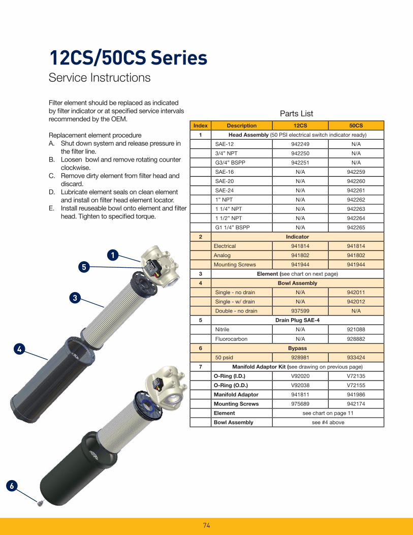
74
12CS/50CS SeriesService Instructions
Filter element should be replaced as indicated by fi lter indicator or at specifi ed service intervals recommended by the OEM.
Replacement element procedureA. Shut down system and release pressure in
the fi lter line.B. Loosen bowl and remove rotating counter
clockwise.C. Remove dirty element from fi lter head and
discard.D. Lubricate element seals on clean element
and install on fi lter head element locator.E. Install reuseable bowl onto element and fi lter
head. Tighten to specifi ed torque.
5
3
1
4
6
Parts ListIndex Description 12CS 50CS
1 Head Assembly (50 PSI electrical switch indicator ready)
SAE-12 942249 N/A
3/4” NPT 942250 N/A
G3/4” BSPP 942251 N/A
SAE-16 N/A 942259
SAE-20 N/A 942260
SAE-24 N/A 942261
1” NPT N/A 942262
1 1/4” NPT N/A 942263
1 1/2” NPT N/A 942264
G1 1/4” BSPP N/A 942265
2 Indicator
Electrical 941814 941814
Analog 941802 941802
Mounting Screws 941944 941944
3 Element (see chart on next page)
4 Bowl Assembly
Single - no drain N/A 942011
Single - w/ drain N/A 942012
Double - no drain 937599 N/A
5 Drain Plug SAE-4
Nitrile N/A 921088
Fluorocarbon N/A 928882
6 Bypass
50 psid 928981 933424
7 Manifold Adaptor Kit (see drawing on previous page)
O-Ring (I.D.) V92020 V72135
O-Ring (O.D.) V92038 V72155
Manifold Adaptor 941811 941986
Mounting Screws 975689 942174
Element see chart on page 11
Bowl Assembly see #4 above

75
12CS/50CS SeriesHow to Order
Select the desired symbol (in the correct position) to construct a model code. Example:
BOX 1 BOX 2 BOX 3 BOX 4 BOX 5 BOX 6 BOX 7 BOX 8
12CS 2 10QE B N K S12 1
BOX 1: Filter Series
Symbol Description
12CS 20 GPM nominal
50CS 40 GPM nominal
BOX 4: Seals
Symbol Description
B Nitrile (NBR)
V Fluorocarbon (FKM)
BOX 8: Options
Symbol Description
1 None
4 Drain port on bowl (50CS only)
BOX 2: Element Length
Symbol Description
1 Single (50CS model only)
2 Double (12CS model only)
BOX 3: Media Code
Symbol Description
02QE Ecoglass III, 2 micron
05QE Ecoglass III, 5 micron
10QE Ecoglass III, 10 micron
20QE Ecoglass III, 20 micron
BOX 6: Bypass
Symbol Pressure Setting
K 50 PSI (3.5 bar)
BOX 7: Ports
Symbol Description
12CS
S12 SAE-12 integral threads
N12 ¾” NPT integral threads
G12 G¾” BSPP (ISO 228)
50CS
S16 SAE-16
S20 SAE-20
S24 SAE-24
N16 1”NPT
N20 1¼” NPT
N24 1½ ” NPT
G20 G1¼” BSPP (ISO 228)
Global products as identifi ed are offered worldwide through all Parker locations and utilize a common ordering code.
Filter Model (Nitrile Seals) Filter Model (Fluorocarbon Seals)
Media 12CS-2 50CS-1 12CS-2 50CS-1
02QE 940765Q 940816Q 937619Q 940881Q
05QE 940764Q 940817Q 937618Q 940882Q
10QE 940763Q 940818Q 937617Q 940883Q
20QE 940762Q 940819Q 937622Q 940884Q
Replacement Elements (Ecoglass)
Please note the bolded options refl ect standard options with a reduced lead-time. Consult factory on all other lead-time options.
BOX 5: Indicator
Symbol Description
N None
E1 Electrical w/12” fl ying leads, right
EL Electrical w/12” fl ying leads, left
A1 Analog w/12” fl ying leads, right
AL Analog w/12” fl ying leads, left
Notes:1. Consult factory.

Notes
76
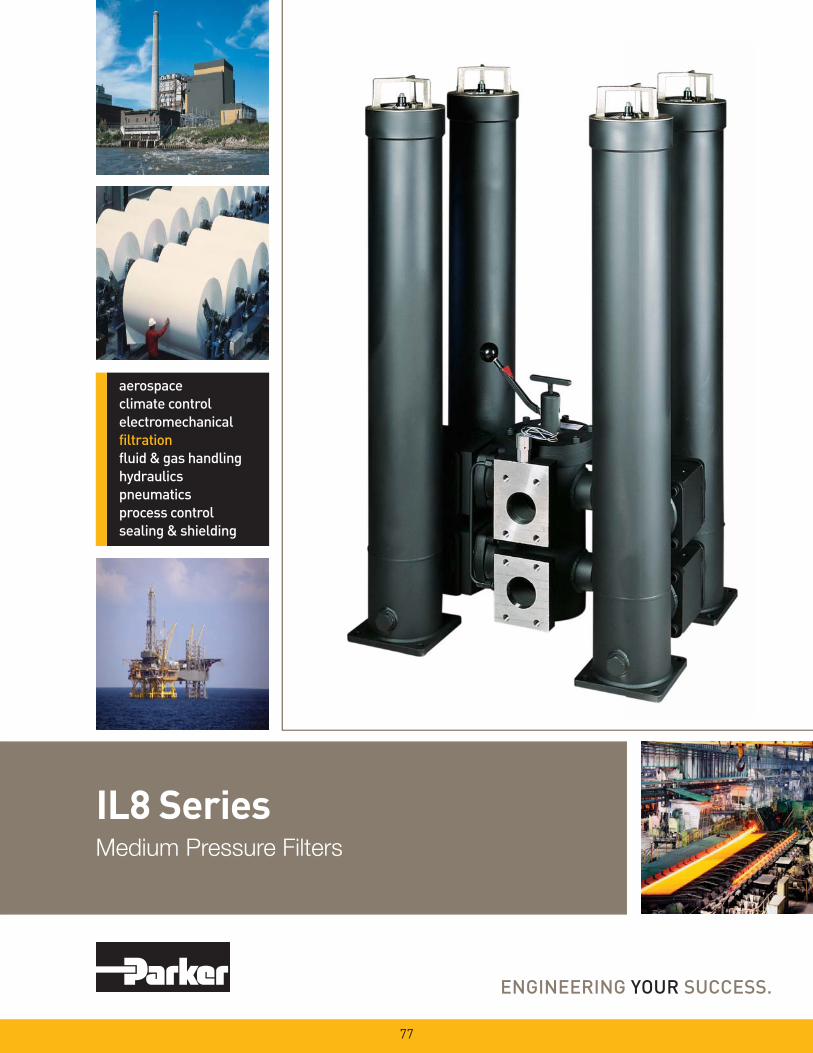
IL8 SeriesMedium Pressure Filters
77
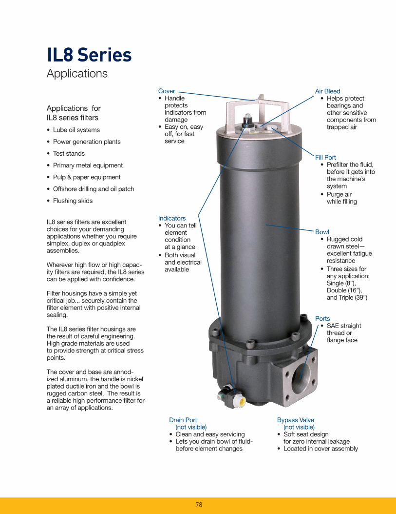
78
IL8 SeriesApplications
Applications for IL8 series fi lters
• Lube oil systems
• Power generation plants
• Test stands
• Primary metal equipment
• Pulp & paper equipment
• Offshore drilling and oil patch
• Flushing skids
IL8 series fi lters are excellent choices for your demanding applications whether you require simplex, duplex or quadplex assemblies.
Wherever high fl ow or high capac-ity fi lters are required, the IL8 series can be applied with confi dence.
Filter housings have a simple yet critical job... securely contain the fi lter element with positive internal sealing.
The IL8 series fi lter housings are the result of careful engineering. High grade materials are used to provide strength at critical stress points.
The cover and base are annod-ized aluminum, the handle is nickel plated ductile iron and the bowl is rugged carbon steel. The result is a reliable high performance fi lter for an array of applications.
Cover• Handle
protects indicators from damage
• Easy on, easy off, for fast service
Indicators• You can tell
element condition at a glance
• Both visual and electrical available
Air Bleed• Helps protect
bearings and other sensitive components from trapped air
Fill Port• Prefi lter the fl uid,
before it gets into the machine’s system
• Purge air while fi lling
Bowl• Rugged cold
drawn steel—excellent fatigue resistance
• Three sizes for any application: Single (8”), Double (16”), and Triple (39”)
Ports• SAE straight
thread or fl ange face
Drain Port (not visible)
• Clean and easy servicing• Lets you drain bowl of fl uid-
before element changes
Bypass Valve (not visible)
• Soft seat design for zero internal leakage
• Located in cover assembly
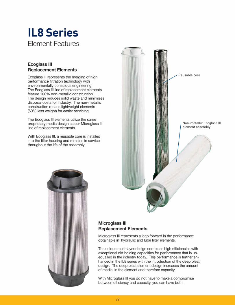
79
IL8 SeriesElement Features
Reusable core
Non-metallic Ecoglass III element assembly
Ecoglass III
Replacement Elements
Ecoglass III represents the merging of high performance fi ltration technology with environmentally conscious engineering. The Ecoglass III line of replacement elements feature 100% non-metallic construction. The design reduces solid waste and minimizes disposal costs for industry. The non-metallic construction means lightweight elements (60% less weight) for easier servicing.
The Ecoglass III elements utilize the same proprietary media design as our Microglass III line of replacement elements.
With Ecoglass III, a reusable core is installed into the fi lter housing and remains in service throughout the life of the assembly.
Microglass III
Replacement Elements
Microglass III represents a leap forward in the performance obtainable in hydraulic and lube fi lter elements.
The unique multi-layer design combines high effi ciencies with exceptional dirt holding capacities for performance that is un-equalled in the industry today. This performance is further en-hanced in the IL8 series with the introduction of the deep pleat design. The deep pleat element design increases the amount of media in the element and therefore capacity.
With Microglass III you do not have to make a compromise between effi ciency and capacity, you can have both.
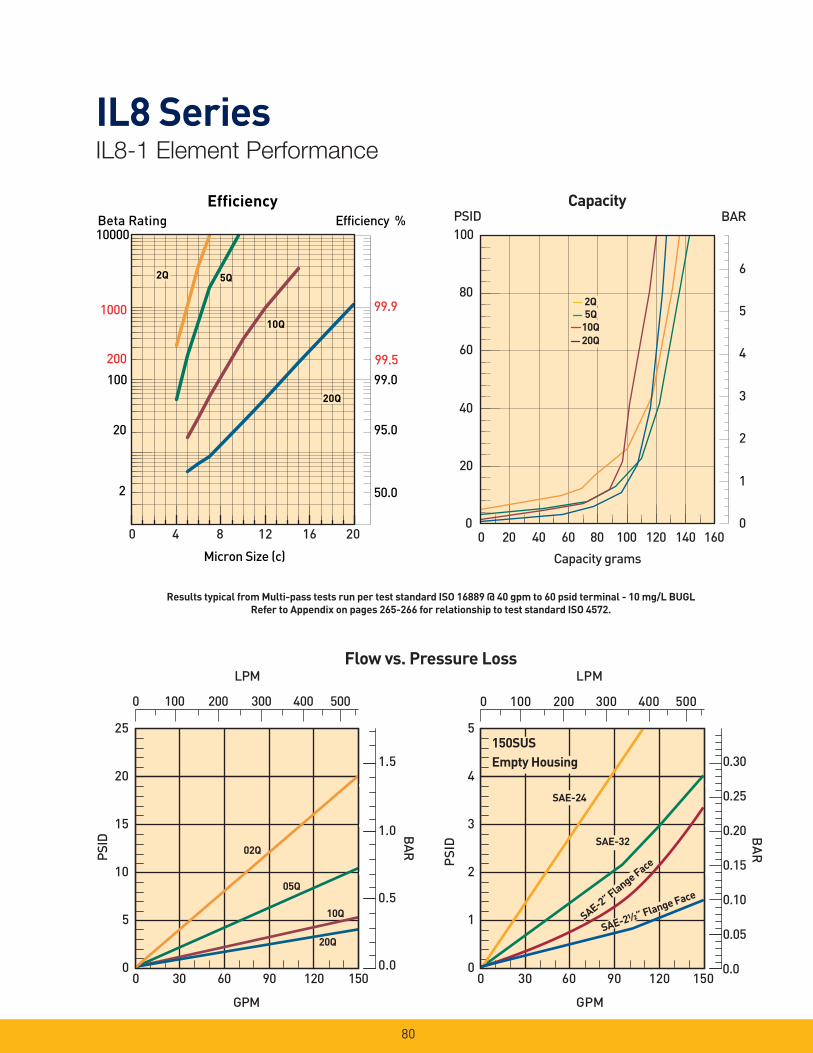
80
IL8 SeriesIL8-1 Element Performance
Efficiency %Efficiency
Beta Rating
1000
10000
99.9
99.599.0100
200
20
2 50.0
95.0
Micron Size (c)
2Q
10Q
20Q
2Q
10Q
20Q
2Q
10Q
20Q
5Q5Q
0 4 8 12 16 20
25
20
15
10
5
0
02Q
20Q
10Q
05Q
LPM
PSID
GPM
1.5
1.0
0.5
0.0
BAR
0 30 60 90 120 150
0 100 200 300 400 500
5
4
3
2
1
0
LPM
PSI
D
GPM
0.30
0.25
0.20
0.15
0.10
0.05
0.0
BA
R
Empty Housing150SUS
SAE-24
SAE-32
SAE-2” Flange Face
SAE-2½” Flange Face
0 100 200 300 400 500
0 30 60 90 120 150
Flow vs. Pressure Loss
0
20
40
60
80
100
0
1
2
3
4
5
6
0 20 40 60 80 100 120 140 160
Capacity grams
BARPSID Capacity
2Q
10Q
20Q
5Q
2Q
10Q
20Q
5Q
Results typical from Multi-pass tests run per test standard ISO 16889 @ 40 gpm to 60 psid terminal - 10 mg/L BUGL
Refer to Appendix on pages 265-266 for relationship to test standard ISO 4572.

81
IL8 SeriesIL8-2 Element Performance
Efficiency %Efficiency
Beta Rating
1000
10000
99.9
99.599.0100
200
20
2 50.0
95.0
Micron Size (c)
2Q
10Q
20Q
2Q
10Q
20Q
2Q
10Q
20Q
5Q5Q
0 4 8 12 16 20
25
20
15
10
5
0
LPM
PSID
GPM
1.0
0.5
0.0
BAR02Q
20Q
150SUS
10Q
05Q
0 200 400 600 800 1000
1.5
0 50 100 150 200 250 300
10
8
6
4
2
0
LPM
PSID
GPM
0.6
0.5
0.4
0.3
0.2
0.1
0.0
BA
R
150SUSEmpty Housing
SAE-24
SAE-32
SAE-
2½” F
lang
e Fac
e
SAE-2” F
lang
e Fa
ce
0 50 100 150 200 250 300
0 200 400 600 800 1000
Flow vs. Pressure Loss
0
1
2
3
4
0
10
20
30
40
50
60
0 60 120 180 240 300 360 420
Capacity grams
BAR PSID Capacity
2Q5Q
20Q10Q
2Q5Q
20Q10Q
Results typical from Multi-pass tests run per test standard ISO 16889 @ 50 gpm to 60 psid terminal - 10 mg/L BUGL
Refer to Appendix on pages 265-266 for relationship to test standard ISO 4572.
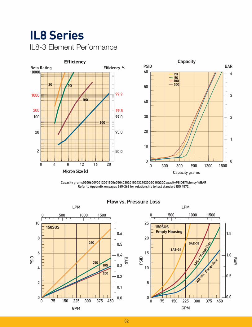
82
IL8 SeriesIL8-3 Element Performance
Efficiency %Efficiency
Beta Rating
1000
10000
99.9
99.599.0100
200
20
2 50.0
95.0
Micron Size (c)
2Q
10Q
20Q
2Q
10Q
20Q
2Q
10Q
20Q
5Q5Q
0 4 8 12 16 20
LPM
10
8
6
4
2
0
02Q
20Q
10QPSID
GPM
150SUS
05Q
0.6
0.5
0.4
0.3
0.2
0.1
0.0
BAR
0 500 1000 1500
0 75 150 225 300 375 450
LPM
25
20
15
10
5
0
PSID
GPM
150SUSEmpty Housing 1.5
1.0
0.5
0.0
BAR
SAE-24
SAE-32
SAE-2½
” Flan
ge Fac
e
SAE-
2” F
lang
e Fac
e
0 500 1000 1500
0 75 150 225 300 375 450
Flow vs. Pressure Loss
BAR PSID Capacity
2Q
10Q5Q
20Q
0
1
2
3
4
0
10
20
30
40
50
60
0 300 600 900 1200 1500
Capacity grams
Capacity grams03006009001200150060504030201004321020Q5Q10Q2QCapacityPSIDEffi ciency %BAR
Refer to Appendix on pages 265-266 for relationship to test standard ISO 4572.

83
IL8 SeriesSpecifi cations: IL8/LL8
*
Pressure Ratings:Maximum Allowable Operating Pressure (MAOP): 500psi (34.5 bar)Rated Fatigue Pressure: 330psi (22.8 bar)Design Safety Factor: 3:1
Operating Temperatures:Buna: -40oF (-40oC) to 225oF (107oC)Fluorocarbon: -15oF (-26oC) to 275oF (135oC)
Element Collapse Rating: 150 psid (10.3 bar)
Element Condition Indicators:Visual (optional)Electrical -heavy duty (optional) SPDT .25 amps (resistive) MAX 5 watts 12 to 28 VDC & 110 to 175 VACNote: Product of switching voltage and current must not exceed wattage rating
Color Coding:White (common)Black (normally open)Blue (normally closed)
Materials:Bowl: low carbon steelCover: anodized aluminumHandle: nickel plated ductile ironBase: anodized aluminum
Shipping Weights (approximate):Single: 40 lbs. (18.1 kg)Double: 50 lbs. (22.7 kg)Triple: 75 lbs. (34 kg)
LL8 Outlet
IL8 Outlet
Inlet
ElementRemoval Clearance
.500 - 13 UNC- 2B x .75 Deep Min. Mounting Holes, 4 Total
Single
Double
Triple
6.25
377.7
93436.77
14.87
Single
Double
Triple
653±7
25.71±.25
1209±747.61±.25
33.3
118.1 95.33.754.65
1.31
101.6
50.8
101.64.0
58.72.31
236±39.28±.12
95.33.75
2.0
4.0
33.31.31
M2
H1
H2
H3
138.2
5.44
141.7
5.58
203.2
8.00
175.3
6.90
Linear Measure: millimeterinch
436±7
17.11±.25
*
Drawings are for reference only. Contact factory for current version.
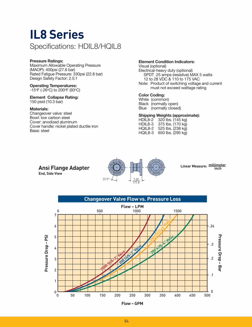
84
IL8 SeriesSpecifi cations: HDIL8/HQIL8
7.00177.8
22.5°
Pressure Ratings:Maximum Allowable Operating Pressure (MAOP): 400psi (27.6 bar)Rated Fatigue Pressure: 330psi (22.8 bar)Design Safety Factor: 2.5:1
Operating Temperatures:-15oF (-26oC) to 200oF (93oC)
Element Collapse Rating: 150 psid (10.3 bar)
Materials: Changeover valve: steelBowl: low carbon steelCover: anodized aluminumCover handle: nickel plated ductile ironBase: steel
Element Condition Indicators:Visual (optional)Electrical-heavy duty (optional) SPDT .25 amps (resistive) MAX 5 watts 12 to 28 VDC & 110 to 175 VACNote: Product of switching voltage and current must not exceed wattage rating
Color Coding:White (common)Black (normally open)Blue (normally closed)
Shipping Weights (approximate):HDIL8-2 320 lbs. (145 kg)HDIL8-3 375 lbs. (170 kg)HQIL8-2 525 lbs. (238 kg)HQIL8-3 650 lbs. (295 kg)
Pres
sure
Dro
p –
PSI
Flow – GPM
7
6
5
4
3
2
1
0
Changeover Valve Flow vs. Pressure LossFlow – LPM
Pressure Drop – B
ar
.24
.3
.2
.1
0
0 500 1000 1500
0 50 100 150 200 250 300 350 400 450 500
2000 SUS–3” Valve
2000 SUS–3” Valve
200 SUS–3” Valve
200 SUS–3” Valve
2000
SUS–4” V
alve
2000
SUS–4” V
alve
200 SUS–4” Valve
200 SUS–4” Valve
Linear Measure: millimeterinchAnsi Flange Adapter
End, Side View

85
EQUALIZING VALVEMOUNTING HOLES .66 DIA THRU 16 TOTAL
¼” SAE-4 STR THD VENT PORT.TORQUE 10-15 FT-LBS.
OPTIONAL ANSI FLANGE ADAPTER
½” SAE-8 STR THD FILL PORT.TORQUE 30-45 FT-LBS.
33.55
228.6
165.16.50
203.28.00
165.16.50
203.28.00
9.00
177.87.00
115.94.56
165.16.50
EQUALIZING VALVE
OPTIONAL ANSI FLANGE ADAPTER
638.8525.15
624.8524.60
587.3523.12
177.87.00
203.28.00
203.28.00
165.16.50
733.528.88
568.311.19
366.714.44
355.6014.00
½” SAE-8 STR THD FILL PORT TORQUE 30-45 FT.-LBS.
MOUNTING HOLES .66 DIA THRU 16 TOTAL
771.5530.38
¼” SAE-4 STR THD VENT PORT TORQUE 10-15 FT.-LBS.
MINIMUM ELEMENT RE-MOVAL CLEARANCE
STANDARD SAE PORTING
1” SAE-16 STR THD DRAIN PORT TORQUE: 85-100 FT-LBS
“M2” STYLE SHOWN TORQUE 30-45 FT-LBS
180° HANDLE ROTATION FOR CHANGE OVER
“H” STYLE SHOWN TORQUE30-45 FT-LBS
COVER HANDLE TORQUE: HAND TIGHT
16.0.63
30011.81
65.52.58
763.7530.07
1320.651.99
(-2)
(-3)692.727.27
1249.549.19
(-2)
(-3)
427.016.81
431.817.0
990.639.0
(-2)
(-3)
Linear Measure: millimeterinch
HDIL8 Top View
HDIL8/HQIL8Side View
HQIL8 Top View
1704.5
IL8 SeriesSpecifi cations: HDIL8/HQIL8
Drawings are for reference only. Contact factory for current version.
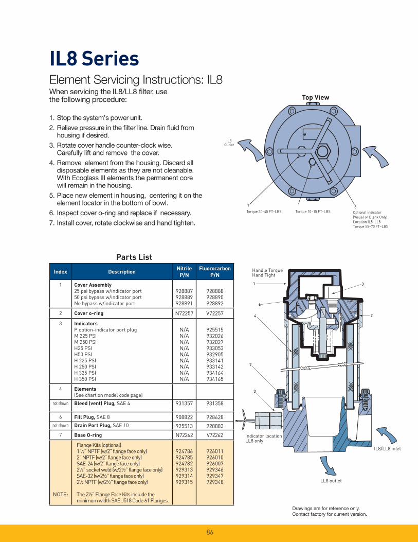
86
IL8 Series
1. Stop the system’s power unit.
2. Relieve pressure in the fi lter line. Drain fl uid from housing if desired.
3. Rotate cover handle counter-clock wise. Carefully lift and remove the cover.
4. Remove element from the housing. Discard alldisposable elements as they are not cleanable. With Ecoglass III elements the permanent core will remain in the housing.
5. Place new element in housing, centering it on the element locator in the bottom of bowl.
6. Inspect cover o-ring and replace if necessary.
7. Install cover, rotate clockwise and hand tighten.
6
4
1
3
3
2
7
Handle Torque Hand Tight
Element Servicing Instructions: IL8When servicing the IL8/LL8 fi lter, use the following procedure:
Parts List
7 3Torque 30–45 FT–LBS Torque 10–15 FT–LBS Optional indicator
(Visual or Blank Only)Location IL8, LL8Torque 55–70 FT–LBS
IL8Outlet
Top View
Indicator location LL8 only
LL8 outlet
IL8/LL8 inlet
Index DescriptionNitrile
P/N
Fluorocarbon
P/N
1 Cover Assembly
25 psi bypass w/indicator port
50 psi bypass w/indicator port
No bypass w/indicator port
928887928889928891
928888928890928892
2 Cover o-ring N72257 V72257
3 Indicators
P option-indicator port plug
M 2 25 PSI
M 2 50 PSI
H 25 PSI
H 50 PSI
H 2 25 PSI
H 2 50 PSI
H 3 25 PSI
H 3 50 PSI
N/AN/AN/AN/AN/AN/AN/AN/AN/A
925515932026932027933053932905933141933142934164934165
4
not shown
Elements
(See chart on model code page)
Bleed (vent) Plug, SAE 4 931357 931358
6
not shown
Fill Plug, SAE 8
Drain Port Plug, SAE 10
908822
925513
928628
928883
7 Base O-ring N72262 V72262
NOTE:
Flange Kits (optional)1 ½” NPTF (w/2” flange face only)2” NPTF (w/2” flange face only)SAE-24 (w/2” flange face only)2½” socket weld (w/2½” flange face only)SAE-32 (w/2½” flange face only)2½ NPTF (w/2½” flange face only)
The 2½” Flange Face Kits include the minimum width SAE J518 Code 61 Flanges.
924786924785924782929313929314929315
926011926010926007929346929347929348
Drawings are for reference only. Contact factory for current version.
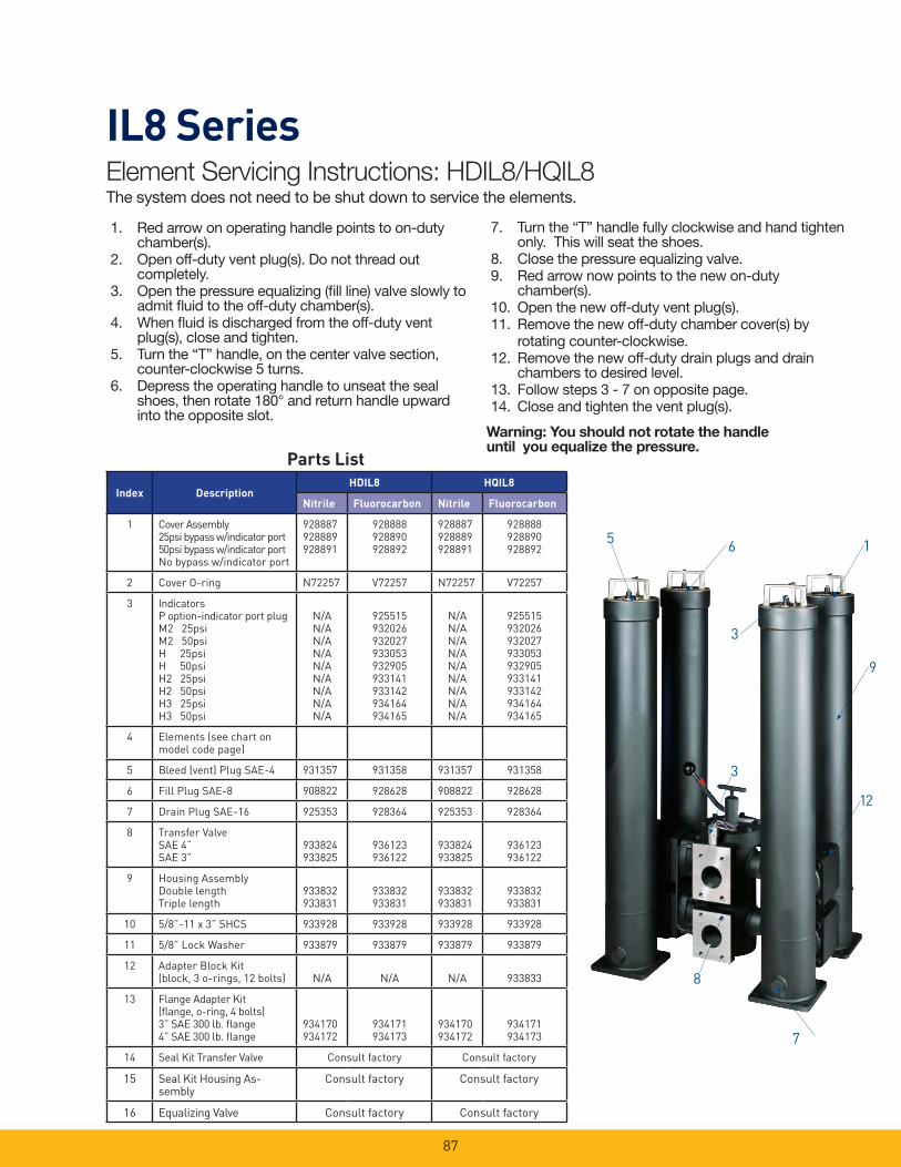
87
IL8 Series
Parts List
1. Red arrow on operating handle points to on-duty chamber(s).
2. Open off-duty vent plug(s). Do not thread out completely.
3. Open the pressure equalizing (fi ll line) valve slowly to admit fl uid to the off-duty chamber(s).
4. When fl uid is discharged from the off-duty vent plug(s), close and tighten.
5. Turn the “T” handle, on the center valve section, counter-clockwise 5 turns.
6. Depress the operating handle to unseat the seal shoes, then rotate 180° and return handle upward into the opposite slot.
7. Turn the “T” handle fully clockwise and hand tighten only. This will seat the shoes.
8. Close the pressure equalizing valve.9. Red arrow now points to the new on-duty
chamber(s).10. Open the new off-duty vent plug(s).11. Remove the new off-duty chamber cover(s) by rotating counter-clockwise.12. Remove the new off-duty drain plugs and drain
chambers to desired level.13. Follow steps 3 - 7 on opposite page.14. Close and tighten the vent plug(s).
Warning: You should not rotate the handle until you equalize the pressure.
Element Servicing Instructions: HDIL8/HQIL8The system does not need to be shut down to service the elements.
1
3
65
7
8
9
12
3
Index DescriptionHDIL8 HQIL8
Nitrile Fluorocarbon Nitrile Fluorocarbon
1 Cover Assembly25psi bypass w/indicator port50psi bypass w/indicator portNo bypass w/indicator port
928887928889928891
928888928890928892
928887928889928891
928888928890928892
2 Cover O-ring N72257 V72257 N72257 V72257
3 IndicatorsP option-indicator port plugM2 25psiM2 50psiH 25psiH 50psiH2 25psiH2 50psiH3 25psiH3 50psi
N/AN/AN/AN/AN/AN/AN/AN/AN/A
925515932026932027933053932905933141933142934164934165
N/AN/AN/AN/AN/AN/AN/AN/AN/A
925515932026932027933053932905933141933142934164934165
4 Elements (see chart onmodel code page)
5 Bleed (vent) Plug SAE-4 931357 931358 931357 931358
6 Fill Plug SAE-8 908822 928628 908822 928628
7 Drain Plug SAE-16 925353 928364 925353 928364
8 Transfer ValveSAE 4”SAE 3”
933824933825
936123936122
933824933825
936123936122
9 Housing AssemblyDouble lengthTriple length
933832933831
933832933831
933832933831
933832933831
10 5/8”-11 x 3” SHCS 933928 933928 933928 933928
11 5/8” Lock Washer 933879 933879 933879 933879
12 Adapter Block Kit (block, 3 o-rings, 12 bolts) N/A N/A N/A 933833
13 Flange Adapter Kit(fl ange, o-ring, 4 bolts)3” SAE 300 lb. fl ange4” SAE 300 lb. fl ange
934170934172
934171934173
934170934172
934171934173
14 Seal Kit Transfer Valve Consult factory Consult factory
15 Seal Kit Housing As-sembly
Consult factory Consult factory
16 Equalizing Valve Consult factory Consult factory
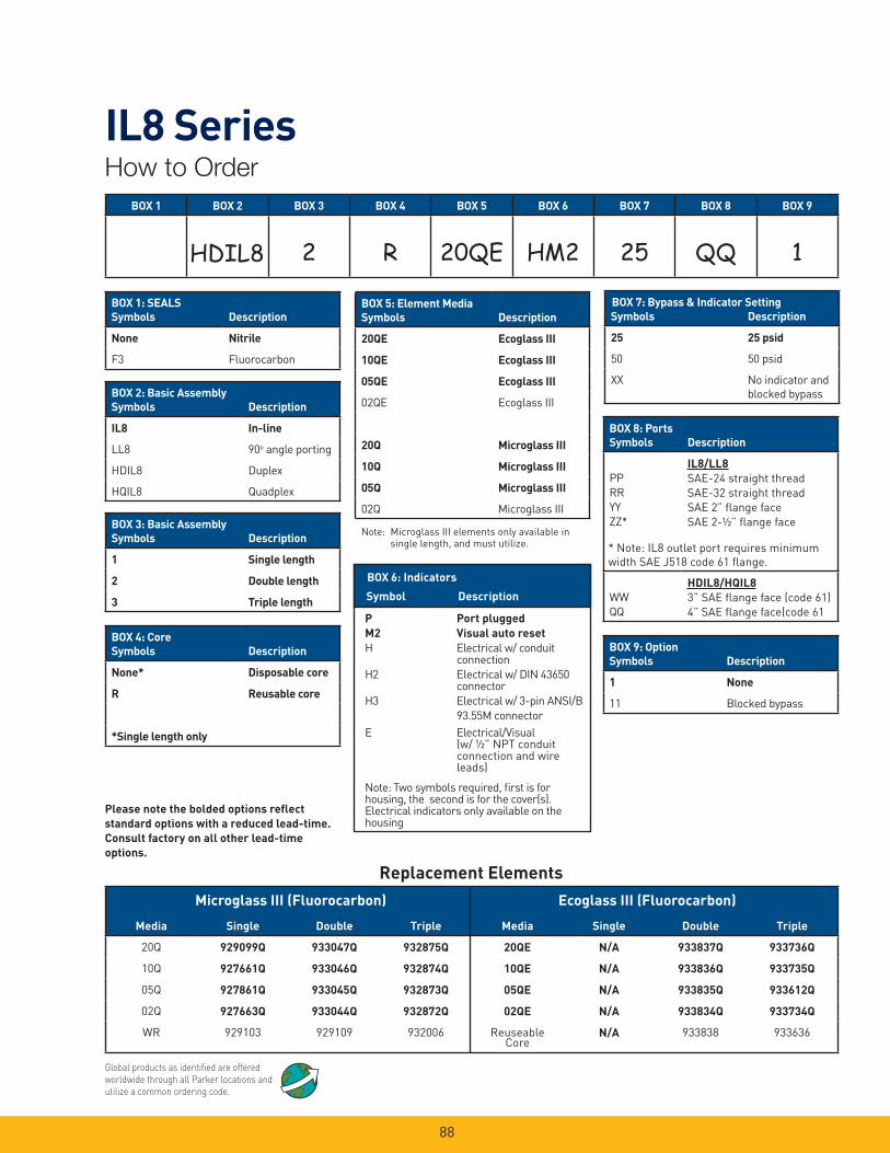
88
IL8 SeriesHow to Order
Global products as identifi ed are offered worldwide through all Parker locations and utilize a common ordering code.
Replacement Elements
BOX 1 BOX 2 BOX 3 BOX 4 BOX 5 BOX 6 BOX 7 BOX 8 BOX 9
2 R 20QE HM2 25 QQ 1
Media Single Double Triple Media Single Double Triple
20Q 929099Q 933047Q 932875Q 20QE N/A 933837Q 933736Q
10Q 927661Q 933046Q 932874Q 10QE N/A 933836Q 933735Q
05Q 927861Q 933045Q 932873Q 05QE N/A 933835Q 933612Q
02Q 927663Q 933044Q 932872Q 02QE N/A 933834Q 933734Q
WR 929103 929109 932006 Reuseable Core
N/A 933838 933636
Microglass III (Fluorocarbon) Ecoglass III (Fluorocarbon)
Please note the bolded options refl ect
standard options with a reduced lead-time.
Consult factory on all other lead-time
options.
Symbol Description
P Port plugged
M2 Visual auto reset
H Electrical w/ conduit connection
H2 Electrical w/ DIN 43650 connector
H3 Electrical w/ 3-pin ANSI/B
93.55M connector
E Electrical/Visual (w/ ½” NPT conduit connection and wire leads)
Note: Two symbols required, fi rst is for housing, the second is for the cover(s). Electrical indicators only available on the housing
BOX 6: Indicators
BOX 1: SEALS
Symbols Description
None Nitrile
F3 Fluorocarbon
BOX 2: Basic Assembly
Symbols Description
IL8 In-line
LL8 90o angle porting
HDIL8 Duplex
HQIL8 Quadplex
BOX 3: Basic Assembly
Symbols Description
1 Single length
2 Double length
3 Triple length
BOX 4: Core
Symbols Description
None* Disposable core
R Reusable core
*Single length only
BOX 5: Element Media
Symbols Description
20QE Ecoglass III
10QE Ecoglass III
05QE Ecoglass III
02QE Ecoglass III
20Q Microglass III
10Q Microglass III
05Q Microglass III
02Q Microglass III
Note: Microglass III elements only available in single length, and must utilize.
Symbols Description
25 25 psid
50 50 psid
XX No indicator and
blocked bypass
BOX 7: Bypass & Indicator Setting
BOX 8: Ports
Symbols Description
PP
RR
YY
ZZ*
IL8/LL8
SAE-24 straight thread
SAE-32 straight thread
SAE 2” fl ange face
SAE 2-½” fl ange face
WW
HDIL8/HQIL8
3” SAE fl ange face (code 61)
4” SAE fl ange face(code 61
BOX 9: Option
Symbols Description
1 None
11 Blocked bypass
* Note: IL8 outlet port requires minimum
width SAE J518 code 61 fl ange.
HDIL8
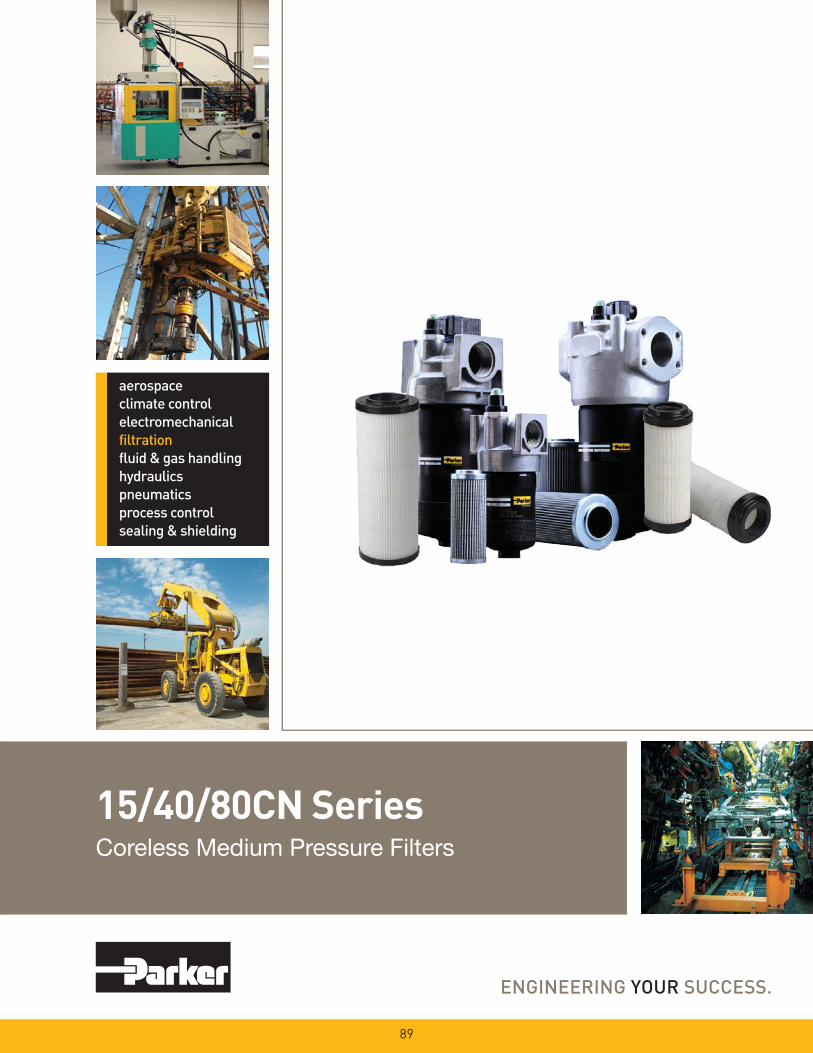
15/40/80CN SeriesCoreless Medium Pressure Filters
89

90
15/40/80CN SeriesApplications
• Compressor Lube Oil• Off-line Filter Loops• Machine Tools
(Automotive Standard)• Hydrostatic Drive
Charge Pumps• Mobile Equipment • Pilot Lines For Servo Controls• Oil Patch Drilling Equipment• Injection Molding
This partial list of applications for Parker “CN” series fi lters has a common factor, the need for an economical, medium pressure range fi lter with excellent fatigue pressure ratings. Prior to the availability of the “CN” fi lter, applications such as those listed were restricted by limitations of a spin-on can, or forced into the higher cost range of high pressure fi lters.
The “CN” series fi lls this gap, and now with the newly increased fatigue rating from 550 to 800 psi, the applications are expanded.
Ecoglass III
Replacement Elements
Ecoglass III represents the merging of high performance fi ltration technology with environmentally conscious engineering. The Ecoglass III line of replacement elements feature 100% non-metallic construction. The design reduces solid waste and minimizes disposal costs for industry. The non-metallic construction means lightweight elements (60% less weight) for easier servicing.
The Ecoglass III elements utilize the same proprietary media design as our Microglass III line of replacement elements.
With Ecoglass III, a reusable core is installed into the fi lter housing and remains in service throughout the life of the assembly.
Features Advantages Benefi ts · 800 psi fatigue rating · Ability to provide reliable service · Reduced downtime due to premature (eight times that of a spin-on) under tough cyclic operating conditions fi lter failures · Can be utilized in applications where high · Reduced costs, better “fi t” pressure fi lters may have been only option for the application
· Diametral (side) seal between · Proven reliability in cyclic applications · No downtime, no leaks head and bowl · Reduced importance of bowl torque · Performs with “real world” service
· Dust Seal · Prevents contamination from building · Easier service, no galling up on bowl / head threads
· Cast aluminum head · Low profi le, lightweight and durable · Less weight, smaller envelop and cleaner appearance
· Standard Ecoglass III elements · Multi-layered design produced high · Great performance value capacity and effi ciency · Reliable performance throughout · Reduces pleat bunching, element life keeps performance consistent · Reduces downtime, maximizes element life
· Complete performance data disclosure · All pertinent information is provided in · No hidden defi ciencies an easy-to-compare format · Easy selection of proper fi ltration
· Visual, electrical or electrical/visual · Check element condition at a glance · Optimize element life, prevent bypassing indicators available · Right style for the application · Matches your system electrical connections

91
15/40/80CN SeriesFeatures
Ports
SAE, NPT or fl ange face (80CN) provides mounting fl exibility.
Diametral (side) Seal
Dust Seal
Protects head and bowl threads from external contamination buildup.
Element Assembly
High effi ciency (Bx>200), high capacity Ecoglass III media with it’s multi-layered design is unequalled in performance.
Element Condition Indicators
Available in visual or electrical, with a choice of several power connections (E3 shown).
Head
Cast aluminum is rugged with small profi le for easy mounting.
Bypass
Cartridge style bypass has good sealing characteristics and low hysteresis. Choice of two settings to match application needs.
Bowl
Anodized aluminum is lightweight and corrosion resistant. Friction grip tape revents slipping when rotating the bowl during service.
Drain Port (optional)
Optional drain port allows for easy element servicing.

92
15CN Series15CN-1 Element Performance
Flow vs. Pressure Loss
Results typical from Multi-pass tests run per test standard ISO 16889 @ 10 gpm to 100 psid terminal - 10 mg/L BUGL
Refer to Appendix on pages 265-266 for relationship to test standard ISO 4572.
Efficiency %Efficiency
Beta Rating
1000
10000
99.9
99.5
99.0100
200
20
2 50.0
95.0
Micron Size (c)
2Q
10Q
20Q
2Q
10Q
20Q
2Q
10Q
20Q
5Q5Q
0 4 8 12 16 20
PSIDCapacity
20Q10Q
5Q2Q
0
1
2
3
4
5
6
0
20
40
60
80
100
0 1 2 3 4 5 6 7
Capacity (grams)
BAR
PS
ID
25
20
15
10
5
0
1.5
1.0
0.5
0.0
GPM
BA
R
LPM
150SUSEMPTY HOUSING
¾” Nominal Port Size
1” Nominal Port Size
0 5 10 15 20
0 10 20 30 40 50 60 70
PS
ID
25
20
15
10
5
0
1.5
1.0
0.5
0.0
GPM
02Q
20Q
10Q
05Q
BA
R
LPM
150SUS
0 10 20 30 40 50 60 70
0 5 10 15 20
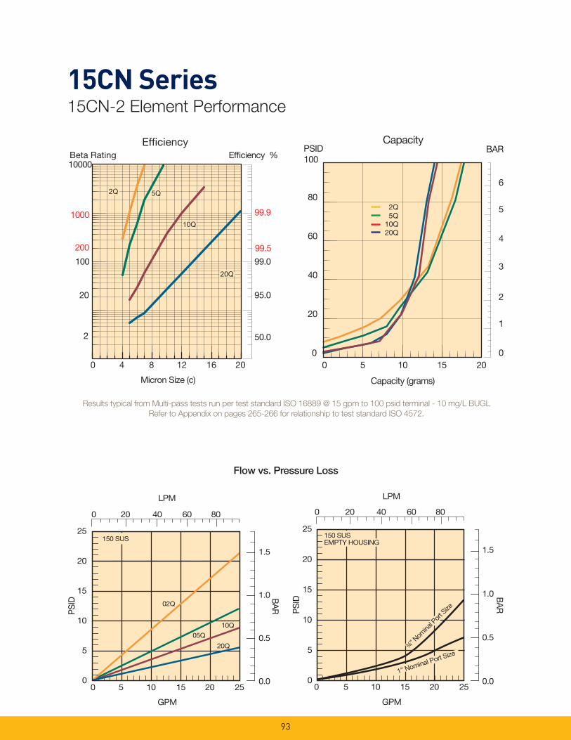
93
15CN Series15CN-2 Element Performance
PS
ID
25
20
15
10
5
0
GPM
02Q
20Q
05Q
BA
R
LPM
150 SUS
1.5
1.0
0.5
0.0
10Q
0 20 40 60 80
0 5 10 15 20 25
PS
ID
25
20
15
10
5
0
GPM
BA
R
LPM
150 SUS
1.5
1.0
0.5
0.0
EMPTY HOUSING
¾” Nom
inal P
ort S
ize
1” Nominal Port Size
0 20 40 60 80
0 5 10 15 20 25
Results typical from Multi-pass tests run per test standard ISO 16889 @ 15 gpm to 100 psid terminal - 10 mg/L BUGL
Refer to Appendix on pages 265-266 for relationship to test standard ISO 4572.
Flow vs. Pressure Loss
Efficiency %Efficiency
Beta Rating
1000
10000
99.9
99.5
99.0100
200
20
2 50.0
95.0
Micron Size (c)
2Q
10Q
20Q
2Q
10Q
20Q
2Q
10Q
20Q
5Q5Q
0 4 8 12 16 20
PSIDCapacity
20Q
2Q5Q
10Q
0
1
2
3
4
5
6
0
20
40
60
80
100
0 5 10 15 20
Capacity (grams)
BAR

94
40CN Series40CN-1 Element Performance
Efficiency %Efficiency
Beta Rating
1000
10000
99.9
99.5
99.0100
200
20
2 50.0
95.0
Micron Size (c)
2Q
10Q
20Q
2Q
10Q
20Q
2Q
10Q
20Q
5Q5Q
0 4 8 12 16 20
Results typical from Multi-pass tests run per test standard ISO 16889 @ 15 gpm to 100 psid terminal - 10 mg/L BUGL
Refer to Appendix on pages 265-266 for relationship to test standard ISO 4572.
Flow vs. Pressure Loss
PSID
Capacity
0
1
2
3
4
5
6
0
20
40
60
80
100
0 10 20 30 40
Capacity grams
2Q5Q
10Q20Q
BAR
PS
ID
25
20
15
10
5
0
GPM
BA
R
LPM
150 SUS
1.5
1.0
0.5
0.0
EMPTY HOUSING
1½” Nominal P
ort Size
0 50 100 150 200 250 300 350
0 20 40 60 80 100
1” N
omina
l Por
t Size
PS
ID
25
20
15
10
5
0
GPM
02Q
20Q
05Q
BA
R
LPM
150 SUS
1.5
1.0
0.5
0.0
10Q
0 20 40 60 80 100
0 50 100 150 200 250 300 350
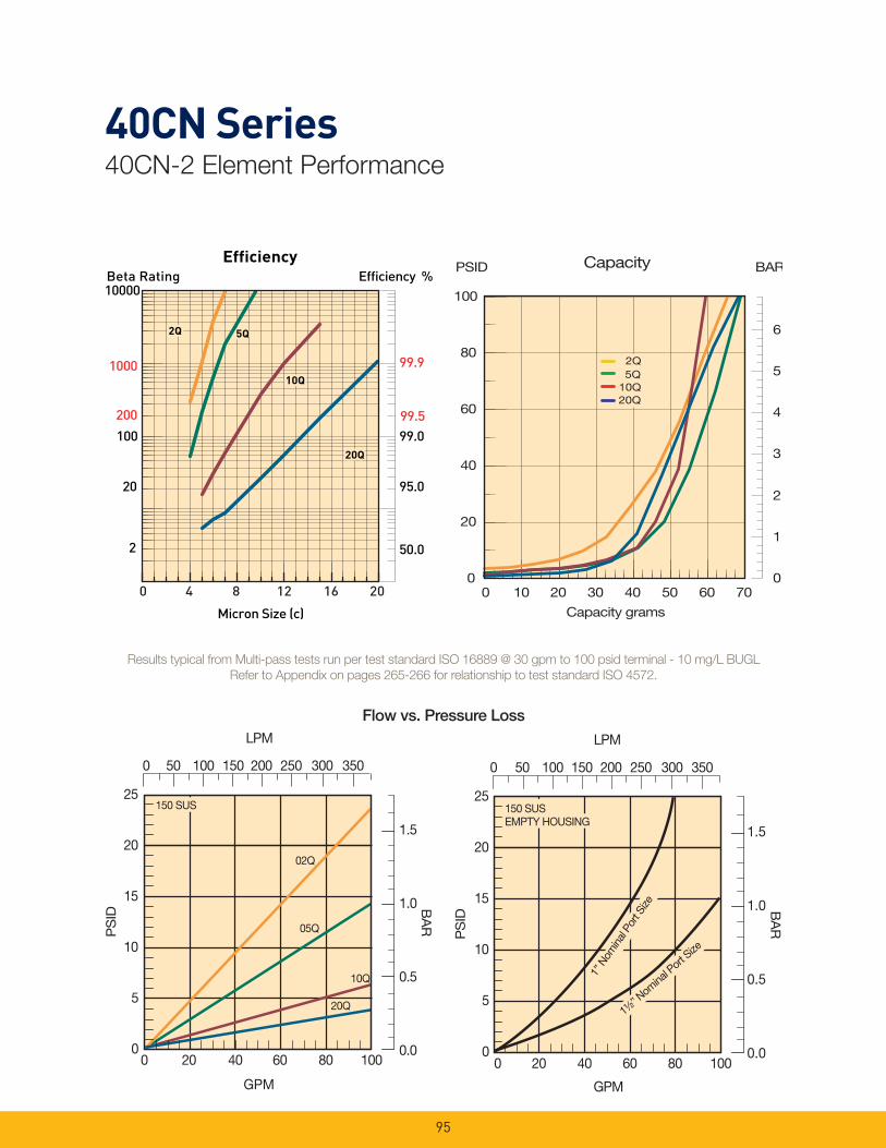
95
40CN Series40CN-2 Element Performance
PS
ID
25
20
15
10
5
0
GPM
02Q
20Q
05Q
BA
R
LPM
150 SUS
1.5
1.0
0.5
0.0
10Q
0 20 40 60 80 100
0 50 100 150 200 250 300 350
Efficiency %Efficiency
Beta Rating
1000
10000
99.9
99.599.0100
200
20
2 50.0
95.0
Micron Size (c)
2Q
10Q
20Q
2Q
10Q
20Q
2Q
10Q
20Q
5Q5Q
0 4 8 12 16 20
PS
ID
25
20
15
10
5
0
GPM
BA
R
LPM
150 SUS
1.5
1.0
0.5
0.0
EMPTY HOUSING
1½” N
omina
l Port
Size
0 50 100 150 200 250 300 350
1” N
omin
al Po
rt Si
ze
0 20 40 60 80 100
PSID Capacity
0
1
2
3
4
5
6
0
20
40
60
80
100
0 10 20 30 40 50 60 70
Capacity grams
BAR
2Q
10Q20Q
5Q2Q
10Q20Q
5Q
Results typical from Multi-pass tests run per test standard ISO 16889 @ 30 gpm to 100 psid terminal - 10 mg/L BUGL
Refer to Appendix on pages 265-266 for relationship to test standard ISO 4572.
Flow vs. Pressure Loss
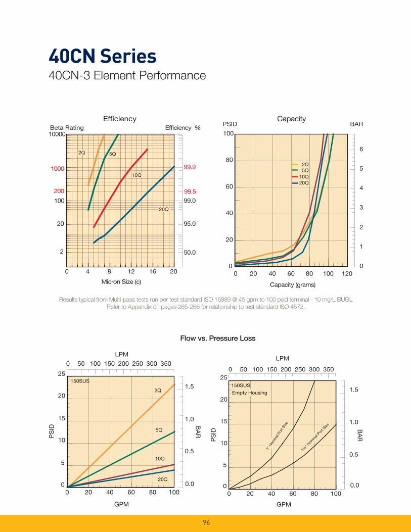
96
40CN Series40CN-3 Element Performance
0.0
0.5
1.5
BA
R
1.0
LPM
0
5
10
15
20
25
PS
ID
0 20 40 60 80 100
GPM
20Q
10Q
5Q
2Q
150SUS
0 50 100 150 200 250 300 350
0.0
0.5
1.0
1.5
GPM
LPM
0
5
10
15
20
25
BA
R
PS
ID
0 20 40 60 80 100
1" N
omin
al P
ort S
ize
1" N
omin
al P
ort S
ize
150SUS
Empty HousingEmpty Housing
0 50 100 150 200 250 300 350
1½" N
omina
l Por
t Size
1½" N
omina
l Por
t Size
Results typical from Multi-pass tests run per test standard ISO 16889 @ 45 gpm to 100 psid terminal - 10 mg/L BUGL
Refer to Appendix on pages 265-266 for relationship to test standard ISO 4572.
Flow vs. Pressure Loss
PSID BARCapacity
2Q
10Q20Q
5Q
0
1
2
3
4
5
6
0
20
40
60
80
100
0 20 40 60 80 100 120
Capacity (grams)
Efficiency %Efficiency
Beta Rating
1000
10000
99.9
99.5
99.0100
200
20
2 50.0
95.0
Micron Size (c)
2Q
10Q
20Q
2Q
10Q
20Q
2Q
10Q
20Q
5Q5Q
0 4 8 12 16 20
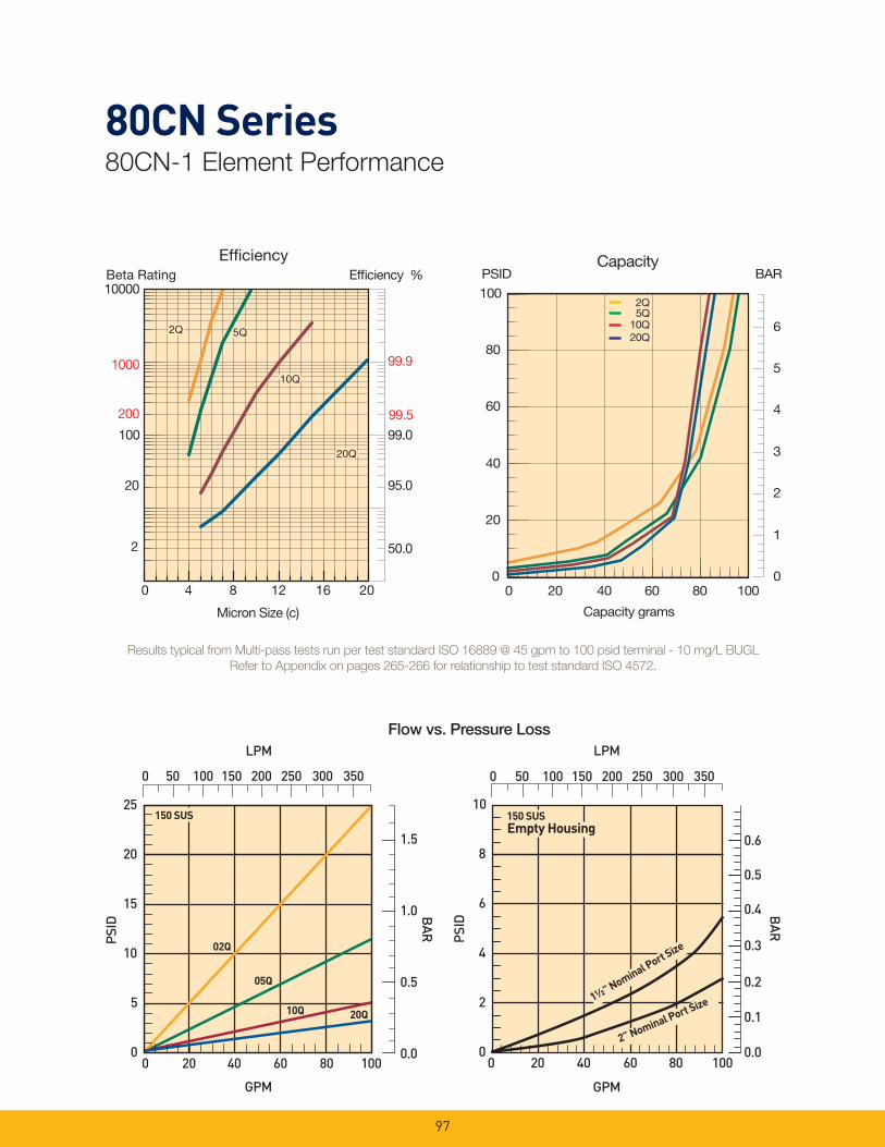
97
80CN Series80CN-1 Element Performance
PSI
D
25
20
15
10
5
0
GPM
02Q
20Q
05Q
BAR
LPM
150 SUS
1.5
1.0
0.5
0.0
10Q
0 50 100 150 200 250 300 350
0 20 40 60 80 100
LPM
PSID
10
8
6
4
2
0
0.6
0.5
0.4
0.3
0.2
0.1
0.0
GPM
Empty Housing
BAR
150 SUS
2” Nominal Port Size1½” Nominal Port Size
0 50 100 150 200 250 300 350
0 20 40 60 80 100
Results typical from Multi-pass tests run per test standard ISO 16889 @ 45 gpm to 100 psid terminal - 10 mg/L BUGL
Refer to Appendix on pages 265-266 for relationship to test standard ISO 4572.
Flow vs. Pressure Loss
PSIDCapacity
2Q
10Q20Q
5Q
0
1
2
3
4
5
6
0 20 40 60 80 100
Capacity grams
0
20
40
60
80
100
BAREfficiency %Efficiency
Beta Rating
1000
10000
99.9
99.5
99.0100
200
20
2 50.0
95.0
Micron Size (c)
2Q
10Q
20Q
2Q
10Q
20Q
2Q
10Q
20Q
5Q5Q
0 4 8 12 16 20
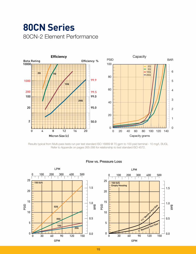
98
80CN Series80CN-2 Element Performance
Efficiency %Efficiency
Beta Rating
1000
10000
99.9
99.599.0100
200
20
2 50.0
95.0
Micron Size (c)
2Q
10Q
20Q
2Q
10Q
20Q
2Q
10Q
20Q
5Q5Q
0 4 8 12 16 20
PSID
25
20
15
10
5
0
GPM
02Q
20Q
05Q
LPM
150 SUS
10Q
BAR
1.5
1.0
0.5
0.0
0 100 200 300 400 500
0 30 60 90 120 150
PSID
25
20
15
10
5
0
GPM
LPM
150 SUSEmpty Housing
BAR
1.5
1.0
0.5
0.0
0 100 200 300 400 500
0 30 60 90 120 150
1½” Nominal P
ort Size
2” Nominal Port Size
Flow vs. Pressure Loss
Results typical from Multi-pass tests run per test standard ISO 16889 @ 70 gpm to 100 psid terminal - 10 mg/L BUGL
Refer to Appendix on pages 265-266 for relationship to test standard ISO 4572.
PSIDCapacity
0
1
2
3
4
5
6
0
20
40
60
80
100
0 20 40 60 80 100 120 140
Capacity grams
BAR
20Q
2Q5Q
10Q
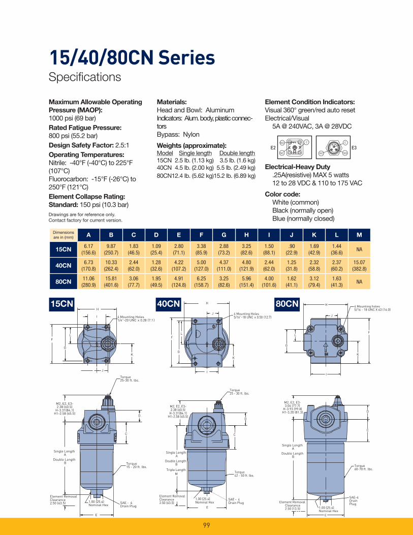
99
15/40/80CN SeriesSpecifi cations
Maximum Allowable Operating
Pressure (MAOP): 1000 psi (69 bar)Rated Fatigue Pressure: 800 psi (55.2 bar)Design Safety Factor: 2.5:1Operating Temperatures:
Nitrile: -40°F (-40°C) to 225°F (107°C)Fluorocarbon: -15°F (-26°C) to 250°F (121°C)Element Collapse Rating:
Standard: 150 psi (10.3 bar)
Element RemovalClearance2.50 (63.5)
H
I
F
G
4 Mounting Holes1/4”-20 UNC x 0.28 (7.1)
K
J
L
Torque25-30 ft. lbs.
D
C
Torque15 - 20 ft. lbs.
SAE - 4Drain Plug
1.00 (25.4)Nominal Hex
E
Single LengthA
Double LengthB
M2, E2, E3-2.38 (60.5)
H-3.31(84.1)H1-2.58 (65.5)
H
F
G
I
K
L
J
Torque25 - 30 ft. lbs.
Element RemovalClearance2.50 (63.5)
Torque42 - 50 ft. lbs.
1.00 (25.4)Nominal Hex
SAE - 4Drain Plug
E
C
D
Single LengthA
Double LengthB
4 Mounting Holes5/16”-18 UNC x 0.50 (12.7)
M2, E2, E3-2.38 (60.5)
H-3.31(84.1)H1-2.58 (65.5)
Triple LengthM
H
L
G
I
K
F
4 Mounting holes5/16 - 18 UNC X 63 (16.0)
D
C
Torque60-70 ft. lbs.
E
SAE-4DrainPlug
1.00 (25.4)Nominal Hex
Element RemovalClearance2.50 (13.5)
Single LengthA
Double LengthB
M2, E2, E3-3.06 (77.7)
H-3.93 (99.8)H1-3.20 (81.3)
J
15CN
E2 E3NO
C
NC
CNO
NC
40CN 80CN
Materials:
Head and Bowl: AluminumIndicators: Alum. body, plastic connec-torsBypass: Nylon
Weights (approximate):Model Single length Double length15CN 2.5 lb. (1.13 kg) 3.5 lb. (1.6 kg)40CN 4.5 lb. (2.00 kg) 5.5 lb. (2.49 kg)80CN 12.4 lb. (5.62 kg) 15.2 lb. (6.89 kg)
Element Condition Indicators:
Visual 360° green/red auto resetElectrical/Visual 5A @ 240VAC, 3A @ 28VDC
Electrical-Heavy Duty
.25A(resistive) MAX 5 watts 12 to 28 VDC & 110 to 175 VAC
Color code:
White (common) Black (normally open) Blue (normally closed)
Dimensions are in (mm) A B C D E F G H I J K L M
15CN6.17
(156.6)9.87
(250.7)1.83
(46.5)1.09
(25.4)2.80
(71.1)3.38
(85.9)2.88
(73.2)3.25
(82.6)1.50
(88.1).90
(22.9)1.69
(42.9)1.44
(36.6)NA
40CN6.73
(170.8)10.33
(262.4)2.44
(62.0)1.28
(32.6)4.22
(107.2)5.00
(127.0)4.37
(111.0)4.80
(121.9)2.44
(62.0)1.25
(31.8)2.32
(58.8)2.37
(60.2)15.07
(382.8)
80CN11.06
(280.9)15.81
(401.6)3.06
(77.7)1.95
(49.5)4.91
(124.8)6.25
(158.7)3.25
(82.6)5.96
(151.4)4.00
(101.6)1.62
(41.1)3.12
(79.4)1.63
(41.3)NA
Drawings are for reference only. Contact factory for current version.
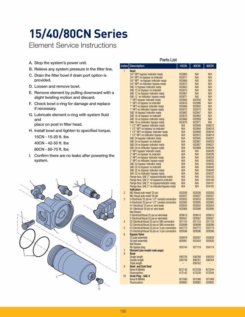
100
A. Stop the system’s power unit.
B. Relieve any system pressure in the fi lter line.
C. Drain the fi lter bowl if drain port option is provided.
D. Loosen and remove bowl.
E. Remove element by pulling downward with a slight twisting motion and discard.
F. Check bowl o-ring for damage and replace if necessary.
G. Lubricate element o-ring with system fl uid and place on post in fi lter head.
H. Install bowl and tighten to specifi ed torque.
15CN - 15-20 ft. lbs
40CN - 42-50 ft. lbs
80CN - 60-70 ft. lbs
I. Confi rm there are no leaks after powering the system.
10
8
9
6
1
7
52 3
4
15/40/80CN SeriesElement Service Instructions
Index Description 15CN 40CN 80CN
1 Head 3/4” NPT bypass/ indicator ready 933865 N/A N/A 3/4” NPT no bypass/ no indicator 933877 N/A N/A 3/4” NPT no bypass/ indicator ready 933869 N/A N/A 3/4” NPT no indicator/ bypass ready 933873 N/A N/A SAE-12 bypass/ indicator ready 933863 N/A N/A SAE-12 no bypass/ no indicator 933875 N/A N/A SAE-12 no bypass/ indicator ready 933867 N/A N/A SAE-12 no indicator/ bypass ready 933871 N/A N/A 1” NPT bypass/ indicator ready 933864 932950 N/A 1” NPT no bypass/ no indicator 933876 932986 N/A 1” NPT no bypass/ indicator ready 933868 932962 N/A 1” NPT no indicator/ bypass ready 933872 932974 N/A SAE-16 bypass/ indicator ready 933862 932947 N/A SAE-16 no bypass/ no indicator 933874 932983 N/A SAE-16 no bypass/ indicator ready 933866 932959 N/A SAE-16 no indicator/ bypass ready 933870 932971 N/A 1 1/2” NPT bypass/ indicator ready N/A 932948 934012 1 1/2” NPT no bypass/ no indicator N/A 932984 934018 1 1/2” NPT no bypass/ indicator ready N/A 932960 934016 1 1/2” NPT no indicator/ bypass ready N/A 932972 934014 SAE-24 bypass/ indicator ready N/A 932945 934027 SAE-24 no bypass/ no indicator N/A 932981 934033 SAE-24 no bypass/ indicator ready N/A 932957 934031 SAE-24 no indicator/ bypass ready N/A 932969 934029 2” NPT bypass/ indicator ready N/A N/A 934020 2” NPT no bypass/ no indicator N/A N/A 934026 2” NPT no bypass/ indicator ready N/A N/A 934024 2” NPT no indicator/ bypass ready N/A N/A 934022 SAE-32 bypass/ indicator ready N/A N/A 934035 SAE-32 no bypass/ no indicator N/A N/A 934042 SAE-32 no bypass/ indicator ready N/A N/A 934040 SAE-32 no indicator/ bypass ready N/A N/A 934037 Flange face, SAE 2” bypass/indicator ready N/A N/A 934103 Flange face, SAE 2” no bypass/no indicator N/A N/A 934109 Flange face, SAE 2” no bypass/indicator ready N/A N/A 934107 Flange face, SAE 2” no indicator/bypass ready N/A N/A 934105 Indicators 2 M2-Visual auto reset/ 25 psi 932026 932026 932026 M2-Visual auto reset/ 50 psi 932027 932027 932027 3 H-Electrical/ 25 psi w/ 1/2” conduit connection 933053 933053 933053 H-Electrical/ 50 psi w/ 1/2” conduit connection 932905 932905 932905 H1-Electrical/ 25 psi w/ wire leads 933054 933054 933054 H1-Electrical/ 50 psi w/ wire leads 932906 932906 932906 Not Shown: E-Electrical/Visual 25 psi w/ wire leads 929610 929610 929610 E-Electrical/Visual 50 psi w/ wire leads 929587 929587 929587 4 E2-Electrical/Visual 25 psi w/ DIN connection 931153 931153 931153 E2-Electrical/Visual 50 psi w/ DIN connection 929599 929599 929599 5 E3-Electrical/Visual 25 psi w/ 3-pin connection 932773 932773 932773 E3-Electrical/Visual 50 psi w/ 3-pin connection 929596 929596 929596 6 Bypass Valve 25 psid assembly 928979 930507 933628 50 psid assembly 928981 933424 933630 Not Shown: No bypass plug 935744 927719 934174 7 Element (see model code page) 8 Bowl Single length 936758 936760 936763 Double length 936759 936761 936764 Triple length – 936762 – 9 Bowl and Dust Seal Buna N (Nitrile) N72142 N72239 N72244 Fluorocarbon V72142 V72239 V72244 10 Drain Plug - SAE-4 Buna N (Nitrile) 921088 921088 921088 Fluorocarbon 928882 928882 928882
Parts List
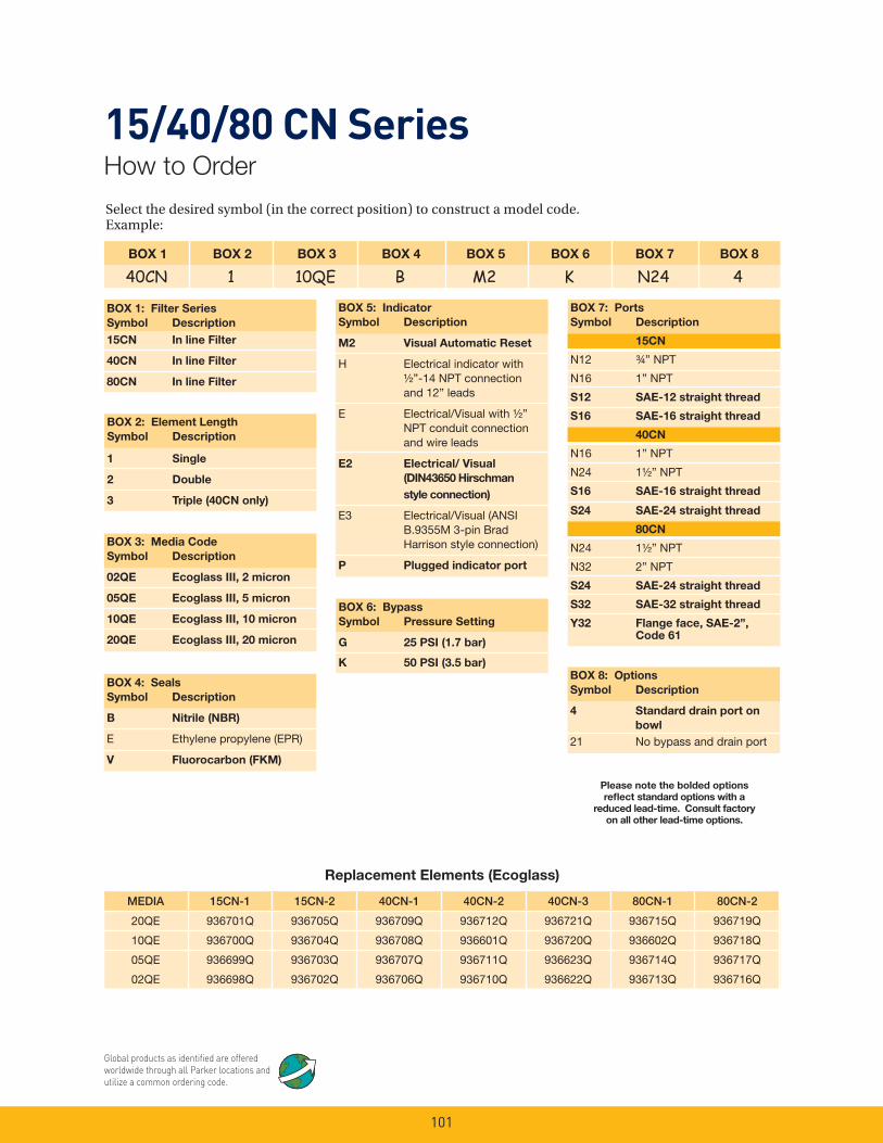
101
Select the desired symbol (in the correct position) to construct a model code. Example:
BOX 1 BOX 2 BOX 3 BOX 4 BOX 5 BOX 6 BOX 7 BOX 8
40CN 1 10QE B M2 K N24 4
BOX 1: Filter Series
Symbol Description
15CN In line Filter
40CN In line Filter
80CN In line Filter
BOX 5: Indicator
Symbol Description
M2 Visual Automatic Reset
H Electrical indicator with ½”-14 NPT connection and 12” leads
E Electrical/Visual with ½” NPT conduit connection and wire leads
E2 Electrical/ Visual
(DIN43650 Hirschman
style connection)
E3 Electrical/Visual (ANSI B.9355M 3-pin Brad Harrison style connection)
P Plugged indicator port
BOX 4: Seals
Symbol Description
B Nitrile (NBR)
E Ethylene propylene (EPR)
V Fluorocarbon (FKM)
BOX 8: Options
Symbol Description
4 Standard drain port on
bowl
21 No bypass and drain port
BOX 2: Element Length
Symbol Description
1 Single
2 Double
3 Triple (40CN only)
BOX 3: Media Code
Symbol Description
02QE Ecoglass III, 2 micron
05QE Ecoglass III, 5 micron
10QE Ecoglass III, 10 micron
20QE Ecoglass III, 20 micron
Please note the bolded options
refl ect standard options with a
reduced lead-time. Consult factory
on all other lead-time options.
BOX 6: Bypass
Symbol Pressure Setting
G 25 PSI (1.7 bar)
K 50 PSI (3.5 bar)
BOX 7: Ports
Symbol Description
15CN
N12 ¾” NPT
N16 1” NPT
S12 SAE-12 straight thread
S16 SAE-16 straight thread
40CN
N16 1” NPT
N24 1½” NPT
S16 SAE-16 straight thread
S24 SAE-24 straight thread
80CN
N24 1½” NPT
N32 2” NPT
S24 SAE-24 straight thread
S32 SAE-32 straight thread
Y32 Flange face, SAE-2”, Code 61
15/40/80 CN SeriesHow to Order
Replacement Elements (Ecoglass)
MEDIA 15CN-1 15CN-2 40CN-1 40CN-2 40CN-3 80CN-1 80CN-2
20QE
10QE
05QE
02QE
936701Q
936700Q
936699Q
936698Q
936705Q
936704Q
936703Q
936702Q
936709Q
936708Q
936707Q
936706Q
936712Q
936601Q
936711Q
936710Q
936721Q
936720Q
936623Q
936622Q
936715Q
936602Q
936714Q
936713Q
936719Q
936718Q
936717Q
936716Q
Global products as identifi ed are offered worldwide through all Parker locations and utilize a common ordering code.

Notes
102
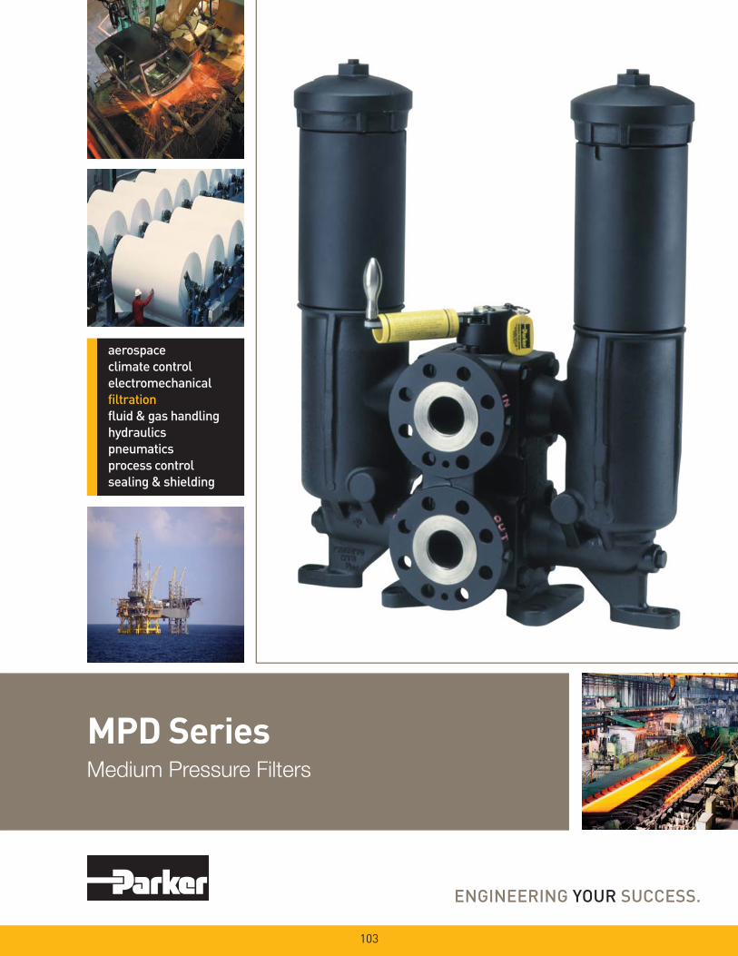
MPD SeriesMedium Pressure Filters
103
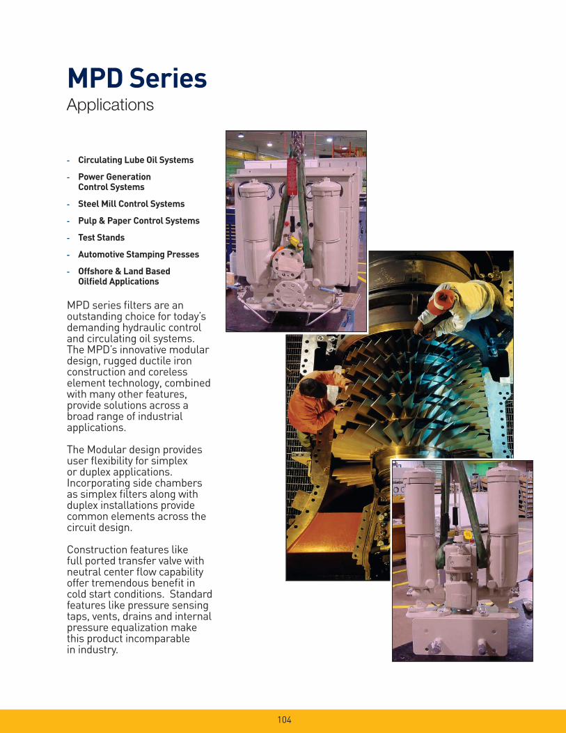
104
MPD SeriesApplications
- Circulating Lube Oil Systems
- Power Generation Control Systems
- Steel Mill Control Systems
- Pulp & Paper Control Systems
- Test Stands
- Automotive Stamping Presses
- Offshore & Land Based Oilfi eld Applications
MPD series fi lters are an outstanding choice for today’s demanding hydraulic control and circulating oil systems. The MPD’s innovative modular design, rugged ductile iron construction and coreless element technology, combined with many other features, provide solutions across a broad range of industrial applications.
The Modular design provides user fl exibility for simplex or duplex applications. Incorporating side chambers as simplex fi lters along with duplex installations provide common elements across the circuit design.
Construction features like full ported transfer valve with neutral center fl ow capability offer tremendous benefi t in cold start conditions. Standard features like pressure sensing taps, vents, drains and internal pressure equalization make this product incomparable in industry.
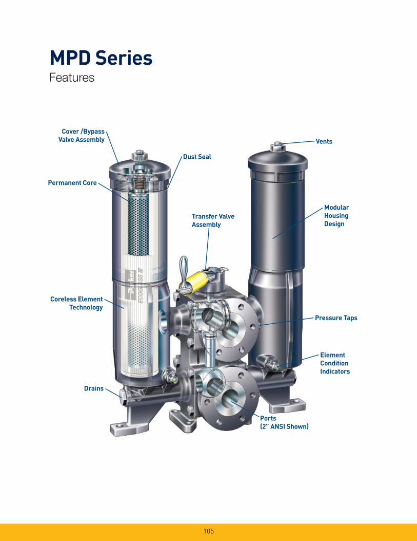
105
MPD SeriesFeatures
Cover /Bypass
Valve Assembly
Permanent Core
Coreless Element
Technology
Drains
Dust Seal
Vents
Transfer Valve
Assembly
Modular
Housing
Design
Element
Condition
Indicators
Pressure Taps
Ports
(2” ANSI Shown)
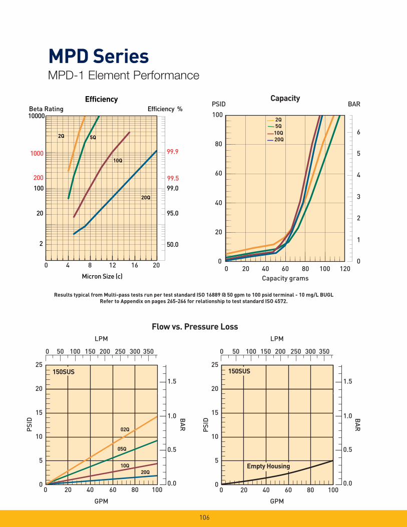
MPD SeriesMPD-1 Element Performance
106
Efficiency %Efficiency
Beta Rating
1000
10000
99.9
99.599.0100
200
20
2 50.0
95.0
Micron Size (c)
2Q
10Q
20Q
2Q
10Q
20Q
2Q
10Q
20Q
5Q5Q
0 4 8 12 16 20 0
20
40
60
80
100
0
1
2
3
4
5
6
Capacity grams
PSID BAR Capacity
5Q
2Q
20Q
10Q
0 20 40 60 80 100 120
LPM
25
20
15
10
5
0
02Q
20Q10Q
PSI
D
GPM
1.5
1.0
0.5
0.0
BA
R
150SUS
05Q
0 50 100 150 200 250 300 350
0 20 40 60 80 100
LPM
25
20
15
10
5
0
PSI
D
GPM
1.5
1.0
0.5
0.0
BA
R
150SUS
Empty Housing
0 50 100 150 200 250 300 350
0 20 40 60 80 100
Flow vs. Pressure Loss
Results typical from Multi-pass tests run per test standard ISO 16889 @ 50 gpm to 100 psid terminal - 10 mg/L BUGL
Refer to Appendix on pages 265-266 for relationship to test standard ISO 4572.
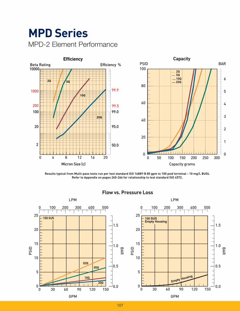
MPD SeriesMPD-2 Element Performance
107
Efficiency %Efficiency
Beta Rating
1000
10000
99.9
99.599.0100
200
20
2 50.0
95.0
Micron Size (c)
2Q
10Q
20Q
2Q
10Q
20Q
2Q
10Q
20Q
5Q5Q
0 4 8 12 16 20
Flow vs. Pressure Loss
0
1
2
3
4
5
6
Capacity grams
0
20
40
60
80
100 PSID BAR
Capacity
20Q10Q
2Q5Q
0 50 100 150 200 250 300
PSI
D
25
20
15
10
5
0
GPM
02Q
20Q
05Q
LPM
150 SUS
10Q
BA
R
1.5
1.0
0.5
0.0
0 100 200 300 400 500
0 30 60 90 120 150
PSI
D
25
20
15
10
5
0
GPM
LPM
150 SUSEmpty Housing
Empty Housing
BA
R
1.5
1.0
0.5
0.00 30 60 90 120 150
0 100 200 300 400 500
Results typical from Multi-pass tests run per test standard ISO 16889 @ 80 gpm to 100 psid terminal - 10 mg/L BUGL
Refer to Appendix on pages 265-266 for relationship to test standard ISO 4572.
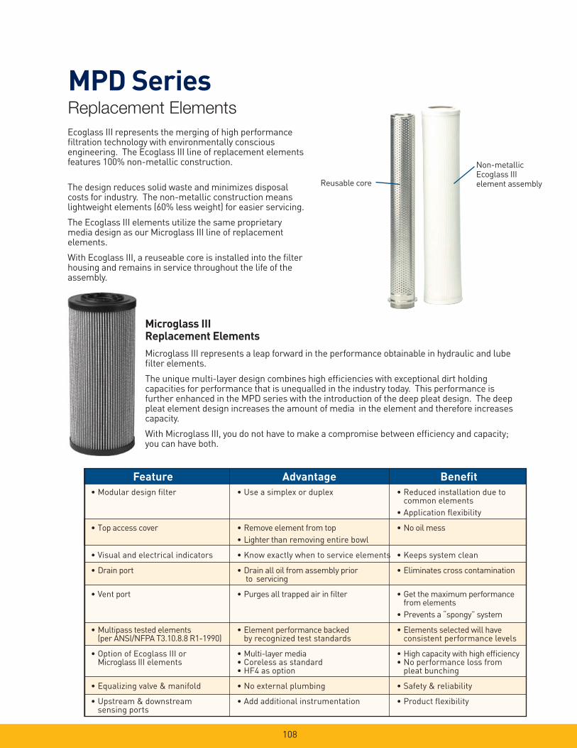
108
MPD SeriesReplacement Elements
Reusable core
Non-metallic Ecoglass III element assembly
Ecoglass III represents the merging of high performance fi ltration technology with environmentally conscious engineering. The Ecoglass III line of replacement elements features 100% non-metallic construction.
The design reduces solid waste and minimizes disposal costs for industry. The non-metallic construction means lightweight elements (60% less weight) for easier servicing.
The Ecoglass III elements utilize the same proprietary media design as our Microglass III line of replacement elements.
With Ecoglass III, a reuseable core is installed into the fi lter housing and remains in service throughout the life of the assembly.
Microglass III Replacement Elements
Microglass III represents a leap forward in the performance obtainable in hydraulic and lube fi lter elements.
The unique multi-layer design combines high effi ciencies with exceptional dirt holding capacities for performance that is unequalled in the industry today. This performance is further enhanced in the MPD series with the introduction of the deep pleat design. The deep pleat element design increases the amount of media in the element and therefore increases capacity.
With Microglass III, you do not have to make a compromise between effi ciency and capacity; you can have both.
Feature Advantage Benefi t
• Modular design fi lter • Use a simplex or duplex • Reduced installation due to common elements
• Application fl exibility
• Top access cover • Remove element from top • No oil mess
• Lighter than removing entire bowl
• Visual and electrical indicators • Know exactly when to service elements • Keeps system clean
• Drain port • Drain all oil from assembly prior • Eliminates cross contamination to servicing
• Vent port • Purges all trapped air in fi lter • Get the maximum performance from elements
• Prevents a “spongy” system
• Multipass tested elements • Element performance backed • Elements selected will have (per ANSI/NFPA T3.10.8.8 R1-1990) by recognized test standards consistent performance levels
• Option of Ecoglass III or • Multi-layer media • High capacity with high effi ciency Microglass III elements • Coreless as standard • No performance loss from • HF4 as option pleat bunching
• Equalizing valve & manifold • No external plumbing • Safety & reliability
• Upstream & downstream • Add additional instrumentation • Product fl exibility sensing ports
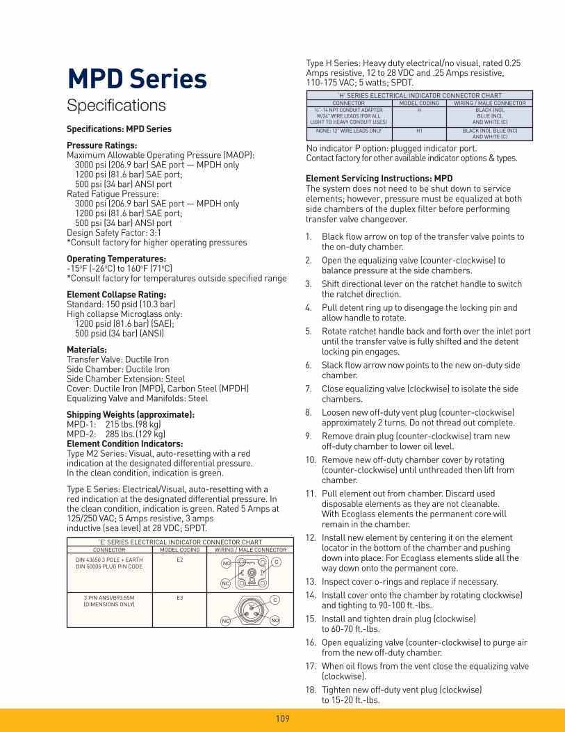
109
MPD SeriesSpecifi cations
1. Black fl ow arrow on top of the transfer valve points to the on-duty chamber.
2. Open the equalizing valve (counter-clockwise) to balance pressure at the side chambers.
3. Shift directional lever on the ratchet handle to switch the ratchet direction.
4. Pull detent ring up to disengage the locking pin and allow handle to rotate.
5. Rotate ratchet handle back and forth over the inlet port until the transfer valve is fully shifted and the detent locking pin engages.
6. Slack fl ow arrow now points to the new on-duty side chamber.
7. Close equalizing valve (clockwise) to isolate the side chambers.
8. Loosen new off-duty vent plug (counter-clockwise) approximately 2 turns. Do not thread out complete.
9. Remove drain plug (counter-clockwise) tram new off-duty chamber to lower oil level.
10. Remove new off-duty chamber cover by rotating (counter-clockwise) until unthreaded then lift from chamber.
11. Pull element out from chamber. Discard used disposable elements as they are not cleanable. With Ecoglass elements the permanent core will remain in the chamber.
12. Install new element by centering it on the element locator in the bottom of the chamber and pushing down into place. For Ecoglass elements slide all the way down onto the permanent core.
13. Inspect cover o-rings and replace if necessary.
14. Install cover onto the chamber by rotating clockwise) and tighting to 90-100 ft.-lbs.
15. Install and tighten drain plug (clockwise) to 60-70 ft.-lbs.
16. Open equalizing valve (counter-clockwise) to purge air from the new off-duty chamber.
17. When oil fl ows from the vent close the equalizing valve (clockwise).
18. Tighten new off-duty vent plug (clockwise) to 15-20 ft.-lbs.
Specifi cations: MPD Series
Pressure Ratings:Maximum Allowable Operating Pressure (MAOP): 3000 psi (206.9 bar) SAE port — MPDH only 1200 psi (81.6 bar) SAE port; 500 psi (34 bar) ANSI portRated Fatigue Pressure: 3000 psi (206.9 bar) SAE port — MPDH only 1200 psi (81.6 bar) SAE port; 500 psi (34 bar) ANSI portDesign Safety Factor: 3:1*Consult factory for higher operating pressures
Operating Temperatures:-15oF (-26oC) to 160oF (71oC)*Consult factory for temperatures outside specifi ed range
Element Collapse Rating: Standard: 150 psid (10.3 bar)High collapse Microglass only: 1200 psid (81.6 bar) (SAE); 500 psid (34 bar) (ANSI)
Materials:Transfer Valve: Ductile IronSide Chamber: Ductile IronSide Chamber Extension: SteelCover: Ductile Iron (MPD), Carbon Steel (MPDH)Equalizing Valve and Manifolds: Steel
Shipping Weights (approximate):MPD-1: 215 lbs. (98 kg)MPD-2: 285 lbs. (129 kg)Element Condition Indicators:Type M2 Series: Visual, auto-resetting with a red indication at the designated differential pressure.In the clean condition, indication is green.
Type E Series: Electrical/Visual, auto-resetting with a red indication at the designated differential pressure. In the clean condition, indication is green. Rated 5 Amps at 125/250 VAC; 5 Amps resistive, 3 amps inductive (sea level) at 28 VDC; SPDT.
Element Servicing Instructions: MPDThe system does not need to be shut down to service elements; however, pressure must be equalized at both side chambers of the duplex fi lter before performing transfer valve changeover.
‘E’ SERIES ELECTRICAL INDICATOR CONNECTOR CHART CONNECTOR MODEL CODING WIRING / MALE CONNECTOR
DIN 43650 3 POLE + EARTH E2
DIN 50005 PLUG PIN CODE
3 PIN ANSI/B93.55M E3
(DIMENSIONS ONLY)
‘H’ SERIES ELECTRICAL INDICATOR CONNECTOR CHART CONNECTOR MODEL CODING WIRING / MALE CONNECTOR
½”-14 NPT CONDUIT ADAPTER H BLACK (NO), W/24” WIRE LEADS (FOR ALL BLUE (NC), LIGHT TO HEAVY CONDUIT USES) AND WHITE (C)
NONE: 12” WIRE LEADS ONLY H1 BLACK (NO), BLUE (NC) AND WHITE (C)
���
��
�
����
Type H Series: Heavy duty electrical/no visual, rated 0.25 Amps resistive, 12 to 28 VDC and .25 Amps resistive, 110-175 VAC; 5 watts; SPDT.
No indicator P option: plugged indicator port.Contact factory for other available indicator options & types.
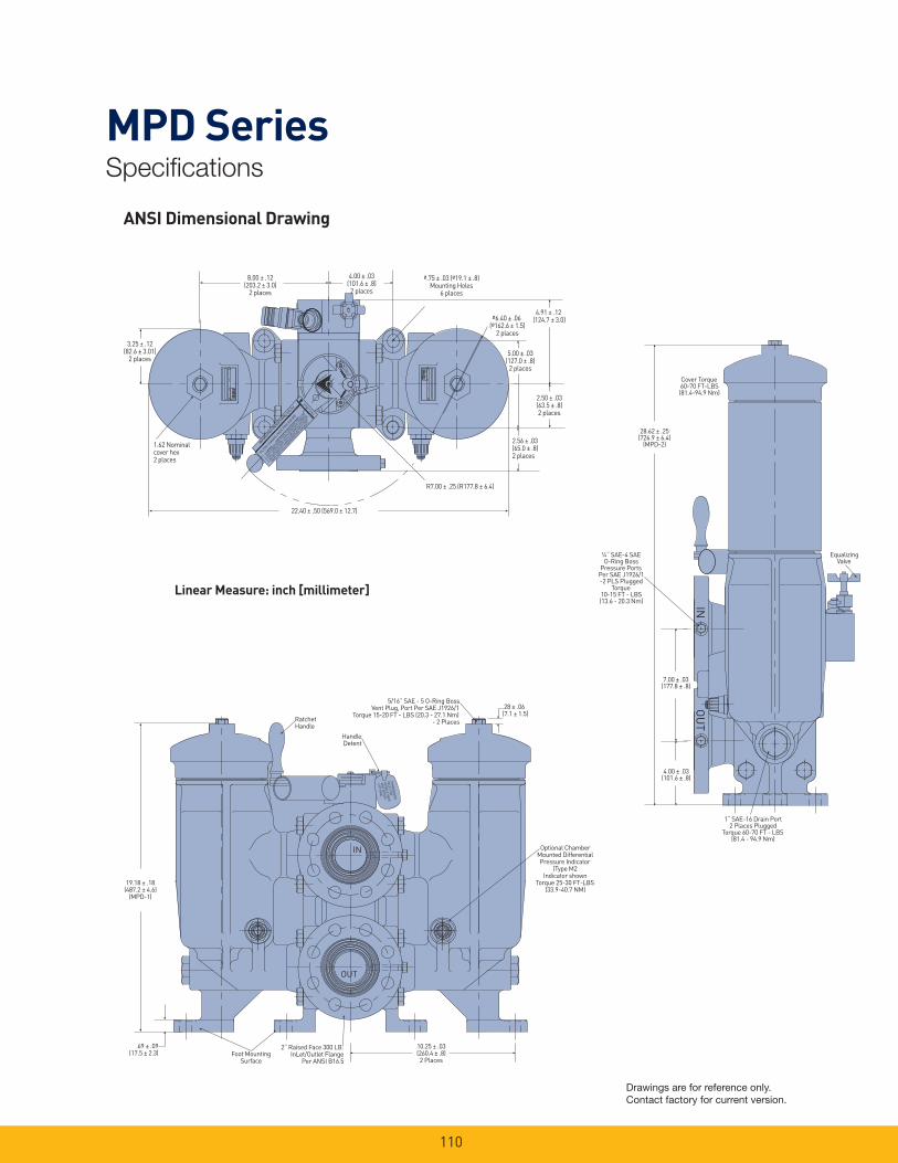
110
MPD SeriesSpecifi cations
INO
UT
Cover Torque60-70 FT-LBS(81.4-94.9 Nm)
28.62 ± .25(726.9 ± 6.4)
(MPD-2)
¼“ SAE-4 SAEO-Ring Boss
Pressure PortsPer SAE J1926/1-2 PLS Plugged
Torque10-15 FT - LBS(13.6 - 20.3 Nm)
7.00 ± .03(177.8 ± .8)
4.00 ± .03(101.6 ± .8)
1“ SAE-16 Drain Port2 Places Plugged
Torque 60-70 FT - LBS(81.4 - 94.9 Nm)
EqualizingValve
DIRECTIONA
3.25 ± .12(82.6 ± 3.01)
2 places
8.00 ± .12(203.2 ± 3.0)
2 places
4.00 ± .03(101.6 ± .8)2 places
ø.75 ± .03 (ø19.1 ± .8)Mounting Holes
6 places
ø6.40 ± .06 (ø162.6 ± 1.5)
2 places
4.91 ± .12 (124.7 ± 3.0)
5.00 ± .03(127.0 ± .8)2 places
2.50 ± .03(63.5 ± .8)2 places
2.56 ± .03(65.0 ± .8)2 places
R7.00 ± .25 (R177.8 ± 6.4)
22.40 ± .50 (569.0 ± 12.7)
1.62 Nominalcover hex2 places
PULL TO
ROTATE
ON-DUTY
ON-DUTY
PULL
TORO
TATE
FILTER CHANGE O
VER PROCEDURE
1. OPEN EQUALIZ
ING VA
LVE TO
BALA
NCE PRESSURE.
2. SHIFT D
IRECTIO
NAL LEVE
R ON R
ATCHET H
ANDLE.
3. PULL
DETE
NT RIN
G TO ALL
OW HANDLE
ROTA
TION.
4. ROTA
TE R
ATCHET H
ANDLE B
ACK & FO
RTH O
VER
IN
LET U
NIT FULL
Y SHIFTE
D/DETE
NT ENGAGES.
ANSI Dimensional Drawing
IN
OUT
5/16” SAE - 5 O-Ring BossVent Plug, Port Per SAE J1926/1
Torque 15-20 FT - LBS (20.3 - 27.1 Nm)- 2 Places
HandleDetent
RatchetHandle
CHAN
GEOVER
INLET FO
R
HAN
DLE OVER
AND
ROTATE
LIFT RIN
G
.28 ± .06(7.1 ± 1.5)
19.18 ± .18(487.2 ± 4.6)
(MPD-1)
.69 ± .09(17.5 ± 2.3) Foot Mounting
Surface
2“ Raised Face 300 LB.InLet/Outlet Flange
Per ANSI B16.5
10.25 ± .03(260.4 ± .8)2 Places
Optional ChamberMounted DifferentialPressure Indicator
(Type M2Indicator shown
Torque 25-30 FT-LBS(33.9-40.7 NM)
Linear Measure: inch [millimeter]
Drawings are for reference only. Contact factory for current version.

111
MPD SeriesSpecifi cations
OU
TIN
¼“ SAE - 4 SAEO-Ring Boss
Pressure PortsPer SAE J1926/1-2 PLS Plugged
Torque10-15 FT - LBS(13.6 - 20.3 Nm)
28.62 ± .25(726.9 ± 6.4)
(MPD-2)
Cover Torque60-70 FT-LBS(81.4-94.9 Nm)
EqualizingValve
4.00 ± .0(101.6 ± .8)
7.00 ± .03(177.8 ± .8)
1“ SAE-16 Drain Port2 Places Plugged
Torque 60-70 FT-LBs(81.4 -94.9 Nm)
PULL
TO
ROTA
TE
ROTATEPULL TO
ON-DUTY
ON-DUTY
1.
OPEN EQUALIZIN
G VALV
E TO B
ALANCE PRESSURE.
2. SHIF
T DIR
ECTIONAL LEVER O
N RATCHET H
ANDLE.
3 P
ULL DETENT R
ING TO A
LLOW HANDLE R
OTATION.
4. R
OTATE RATCHET H
ANDLE BACK &
FORTH OVER
IN
LET UNTIL FULLY S
HIFTED/D
ETENTEN GAGES.
DIRECTIONAL
FILTER CHANGE O
VER PROCEDURE
FILTER CHANGE OVER PROCEDURE
3.25 ± .12(82.6 ± 3.0)2 places
1.62 Nominalcover hex2 places
22.40 ± .50 (569.0 ± 12.7)
R7.00 ± .25 (R177.8 ± 6.4)
2.00 ± .03(50.8 ± .8)2 places
2.50 ± .03(63.5 ± .8)2 places
5.00 ± .03(127.0 ± .8)2 places
4.91 ± .12(124.7 ± 3.0)ø6.40 ± .06
(ø162.6 ± 1.5)2 places
ø.75 ± .03 (ø19.1 ± .8)Mounting Holes
6 places
4.00 ± .03(101.6 ± .8)2 places
8.00 ± .12(203.2 ± 3.0)
2 places
SAE Dimensional Drawing
Linear Measure: inch [millimeter]
CH
ANG
EOVER
INLET FO
R
HAN
DLE O
VER
AND
RO
TATE
LIFT RIN
G
IN
OUT
.28 ± .06[7.1 ± 1.5]
Optional ChamberMounted DifferentialPressure Indicator
(Type M2Indicator shown)
Torque 25-30 FT-LBS[33.9-40.7 Nm]
10.25 ± .03[260.4 ± .8]
2 PlacesFoot Mounting
Surface
.69 ± .09[17.5 ± 2.3]
2 SAE Code 61Inlet/Outlet Flange
Per SAE J518
19.18 ± .18[487.2 ± 4.6]
(MPD-1)
RatchetHandle
HandleDetent
5/16 SAE - 5 O-Ring BossVent Plug, Port Per SAE J1926/1
Torque 15-20 FT - LBS [20.3 - 27.1 Nm]- 2 Places
Drawings are for reference only. Contact factory for current version.
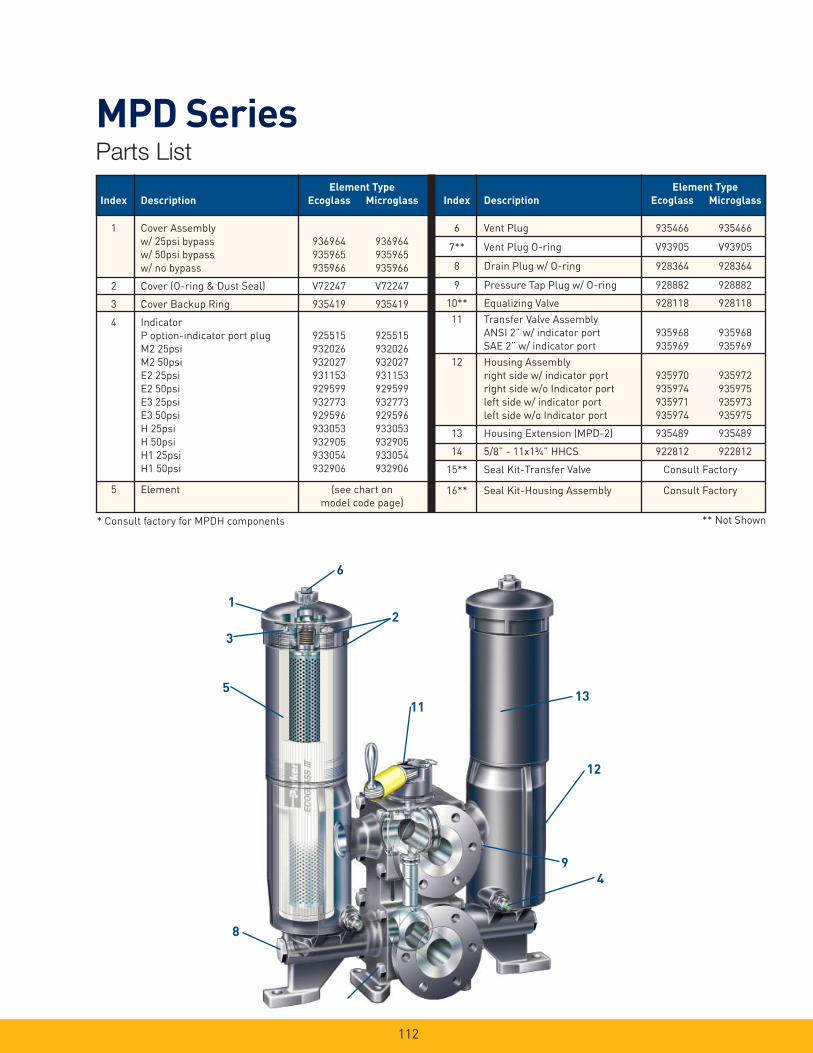
112
MPD SeriesParts List
Element Type
Index Description Ecoglass Microglass
1 Cover Assembly
w/ 25psi bypass 936964 936964
w/ 50psi bypass 935965 935965
w/ no bypass 935966 935966
2 Cover (O-ring & Dust Seal) V72247 V72247
3 Cover Backup Ring 935419 935419
4 Indicator
P option-indicator port plug 925515 925515
M2 25psi 932026 932026
M2 50psi 932027 932027
E2 25psi 931153 931153
E2 50psi 929599 929599
E3 25psi 932773 932773
E3 50psi 929596 929596
H 25psi 933053 933053
H 50psi 932905 932905
H1 25psi 933054 933054
H1 50psi 932906 932906
5 Element (see chart on
model code page)
Element Type
Index Description Ecoglass Microglass
6 Vent Plug 935466 935466
7** Vent Plug O-ring V93905 V93905
8 Drain Plug w/ O-ring 928364 928364
9 Pressure Tap Plug w/ O-ring 928882 928882
10** Equalizing Valve 928118 928118
11 Transfer Valve Assembly
ANSI 2” w/ indicator port 935968 935968
SAE 2” w/ indicator port 935969 935969
12 Housing Assembly
right side w/ indicator port 935970 935972
right side w/o Indicator port 935974 935975
left side w/ indicator port 935971 935973
left side w/o Indicator port 935974 935975
13 Housing Extension (MPD-2) 935489 935489
14 5/8” - 11x1¾” HHCS 922812 922812
15** Seal Kit-Transfer Valve Consult Factory
16** Seal Kit-Housing Assembly Consult Factory
** Not Shown
8
2
11
12
9
5
4
13
6
1
3
* Consult factory for MPDH components
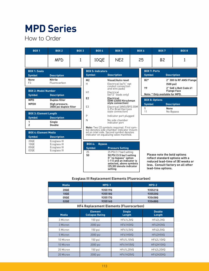
113
MPD SeriesHow to Order
HF4 Replacement Elements (Fluorocarbon)
Media MPD-1 MPD-2
20QE 935519Q 935521Q
10QE 935518Q 935520Q
05QE 935517Q 935458Q
02QE 935516Q 935488Q
Ecoglass III Replacement Elements (Fluorocarbon)
Media
Element
Collapse Rating
Single
Length
Double
Length
3 Micron 150 psi HF41L3VQ HF42L3VQ
3 Micron 2000 psi HF41H3VQ HF42H3VQ
5 Micron 150 psi HF41L5VQ HF42L5VQ
5 Micron 2000 psi HF41H5VQ HF42H5VQ
10 Micron 150 psi HF41L10VQ HF42L10VQ
10 Micron 2000 psi HF41H10VQ HF42H10VQ
20 Micron 150 psi HF41L20VQ HF42L20VQ
20 Micron 2000 psi HF41H20VQ HF42H20VQ
BOX 5: Indicators
Symbol Description
BOX 6: Bypass
BOX 2: Model Number
Symbol Description
MPD Duplex fi lter
MPDH High pressure, 3000 psi duplex fi lter
BOX 3: Element Length
Symbol Description
1 Single
2 Double
Symbol Pressure Setting
25 25 PSI (1.7 bar) setting50 50 PSI (3.5 bar) setting If “no bypass” option (-11) and an indicator is selected, above symbols (25,50) denote indicator setting
BOX 1: Seals
Symbol Description
None Nitrile
F3 Fluorocarbon
BOX 4: Element Media
Symbol Description
20QE Ecoglass III10QE Ecoglass III05QE Ecoglass III02QE Ecoglass III
M2 Visual/Auto reset
H Electrical (w/½” npt conduit connection and wire pads)
H1 Electrical(w/12” leads only)
E2 Electrical (DIN 43650 Hirschman style connection)
E3 Electrical (ANSI/B93.55M3-Pin Brad Harrison style connection)
P Indicator port plugged
N No side chamberindicator port
Note: Two (2) symbols required. First sym-bol denotes side chamber indicator mount-ed on inlet side. Second symbol denotes indicator on equalizing valve manifold.
BOX 8: Options
Symbol Description
1 None
11 No Bypass
BOX 1 BOX 2 BOX 3 BOX 4 BOX 5 BOX 6 BOX 7 BOX 8
BOX 7: Ports
Symbol Description
B2* 2” 300 lb RF ANSI Flange
(500 psi)
Y9 2” SAE 4 Bolt Code 61 Flange Face
Note: * Only available for MPD.
Please note the bold options refl ect standard options with a reduced lead-time of (8) weeks or less. Consult factory on all other lead-time options.
MPD 1 10QE NE2 25 B2 1

Notes
114

15P/30P SeriesHigh Pressure Filters
115
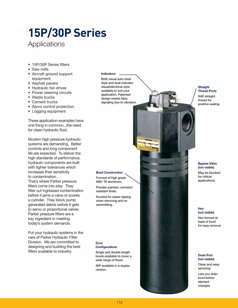
15P/30P SeriesApplications
116
• 15P/30P Series fi lters• Saw mills• Aircraft ground support
equipment• Asphalt pavers• Hydraulic fan drives• Power steering circuits• Waste trucks• Cement trucks• Servo control protection• Logging equipment
These application examples have one thing in common...the need for clean hydraulic fl uid.
Modern high pressure hydraulic systems are demanding. Better controls and long component life are expected. To deliver the high standards of perfor mance, hydraulic components are built with tighter tolerances which increases their sensitivity to contamination.That’s where Parker pressure fi lters come into play. They fi lter out ingressed contamination before it jams a valve or scores a cylinder. They block pump generated debris before it gets to servo or proportional valves. Parker pressure fi lters are a key ingredient in meeting today’s system demands.
Put your hydraulic systems in the care of Parker Hydraulic Filter Division. We are committed to designing and building the best fi lters available to industry.
Indicators
Both visual auto reset style and dual indicator visual/electrical style available to suit your application. Patented design resists false signaling due to vibration.
Bypass Valve
(not visible)
May be blocked for critical applications
Bowl Construction
Formed of high grade 6061 T6 aluminum.
Powder painted, corrosion resistant fi nish.
Knurled for easier ripping when removing and re-assembling.
Straight
Thread Ports
SAE straight thread for positive sealing
Bowl Confi gurations
Single and double length bowls available to cover a wide range of fl ows.
30P available in a duplex version.
Drain Port
(not visible)
Clean and easy servicing
Lets you drain bowl before element changes
Hex
(not visible)
Hex formed at base of bowl for easy removal
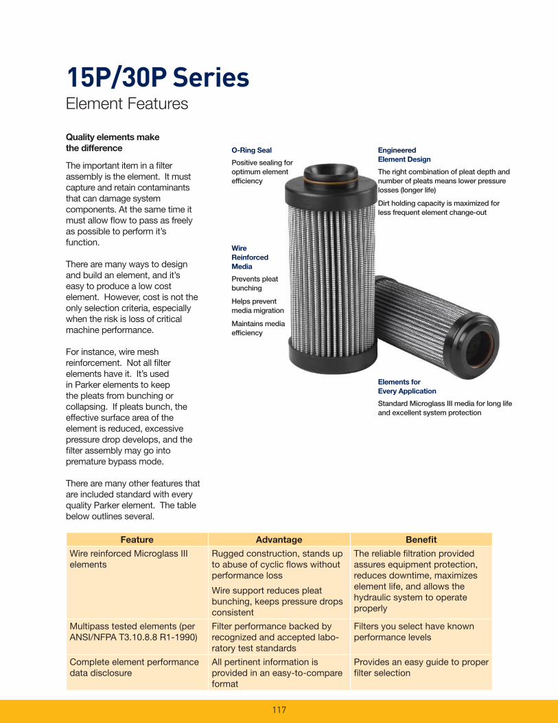
15P/30P SeriesElement Features
117
Quality elements make
the difference
The important item in a fi lter assembly is the element. It must capture and retain contaminants that can damage system components. At the same time it must allow fl ow to pass as freely as possible to perform it’s function.
There are many ways to design and build an element, and it’s easy to produce a low cost element. However, cost is not the only selection criteria, especially when the risk is loss of critical machine performance.
For instance, wire mesh reinforcement. Not all fi lter elements have it. It’s used in Parker elements to keep the pleats from bunching or collapsing. If pleats bunch, the effective surface area of the element is reduced, excessive pressure drop develops, and the fi lter assembly may go into prema ture bypass mode. There are many other features that are included standard with every qual ity Parker element. The table below outlines several.
O-Ring Seal
Positive sealing for optimum element effi ciency
Wire
Reinforced
Media
Prevents pleat bunching
Helps prevent media migration
Maintains media effi ciency
Engineered
Element Design
The right combination of pleat depth and number of pleats means lower pressure losses (longer life)
Dirt holding capacity is maximized for less frequent element change-out
Elements for
Every Application
Standard Microglass III media for long life and excellent system protection
Feature Advantage Benefi t
Wire reinforced Microglass III elements
Rugged construction, stands up to abuse of cyclic fl ows without performance loss
Wire support reduces pleat bunching, keeps pressure drops consistent
The reliable fi ltration provided assures equipment protection, reduces downtime, maximizes element life, and allows the hydraulic system to operate properly
Multipass tested elements (per ANSI/NFPA T3.10.8.8 R1-1990)
Filter performance backed by recognized and accepted labo-ratory test standards
Filters you select have known performance levels
Complete element performance data disclosure
All pertinent information is provided in an easy-to-compare format
Provides an easy guide to proper fi lter selection
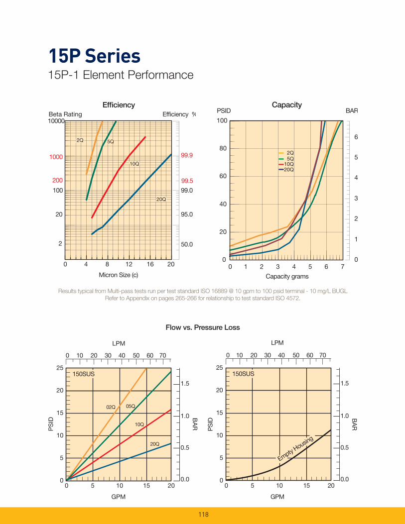
15P Series15P-1 Element Performance
118
Flow vs. Pressure Loss
Results typical from Multi-pass tests run per test standard ISO 16889 @ 10 gpm to 100 psid terminal - 10 mg/L BUGL
Refer to Appendix on pages 265-266 for relationship to test standard ISO 4572.
Efficiency %Efficiency
Beta Rating
1000
10000
99.9
99.5
99.0100
200
20
2 50.0
95.0
Micron Size (c)
2Q
10Q
20Q
2Q
10Q
20Q
2Q
10Q
20Q
5Q5Q
0 4 8 12 16 20
PSIDCapacity
20Q10Q
5Q2Q
0
1
2
3
4
5
6
0
20
40
60
80
100
0 1 2 3 4 5 6 7
Capacity grams
BAR
LPM
25
20
15
10
5
0
05Q
20Q
10Q
PS
ID
GPM
1.5
1.0
0.5
0.0
BA
R
150SUS
02Q
0 5 10 15 20
0 10 20 30 40 50 60 70
LPM
25
20
15
10
5
0
PS
ID
GPM
1.5
1.0
0.5
0.0
BA
R
150SUS
Empty Housin
g
0 10 20 30 40 50 60 70
0 5 10 15 20

15P Series15P-2 Element Performance
119
Flow vs. Pressure Loss
Results typical from Multi-pass tests run per test standard ISO 16889 @ 15 gpm to 100 psid terminal - 10 mg/L BUGL
Refer to Appendix on pages 265-266 for relationship to test standard ISO 4572.
Efficiency %Efficiency
Beta Rating
1000
10000
99.9
99.5
99.0100
200
20
2 50.0
95.0
Micron Size (c)
2Q
10Q
20Q
2Q
10Q
20Q
2Q
10Q
20Q
5Q5Q
0 4 8 12 16 20
PSID BARCapacity
20Q
2Q5Q
10Q
0
1
2
3
4
5
6
0
20
40
60
80
100
0 5 10 15 20
Capacity (grams)
0 20 40 60 80
LPM
25
20
15
10
5
0
02Q
20Q10Q
PS
ID
GPM
1.5
1.0
0.5
0.0
BA
R
150SUS
05Q
0 5 10 15 20 25
LPM
25
20
15
10
5
0
PS
ID
GPM
1.5
1.0
0.5
0.0
BA
R
150SUS
Empt
y Hou
sing
0 20 40 60 80
0 5 10 15 20 25
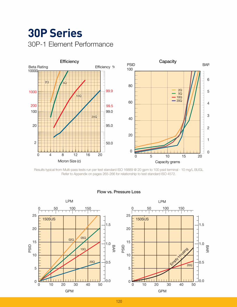
30P Series30P-1 Element Performance
120
Flow vs. Pressure Loss
Results typical from Multi-pass tests run per test standard ISO 16889 @ 20 gpm to 100 psid terminal - 10 mg/L BUGL
Refer to Appendix on pages 265-266 for relationship to test standard ISO 4572.
Efficiency %Efficiency
Beta Rating
1000
10000
99.9
99.5
99.0100
200
20
2 50.0
95.0
Micron Size (c)
2Q
10Q
20Q
2Q
10Q
20Q
2Q
10Q
20Q
5Q5Q
0 4 8 12 16 200
1
2
3
4
5
6
0
20
40
60
80
100
0 5 10 15 20
Capacity grams
PSID BARCapacity
20Q
2Q
10Q5Q
LPM
25
20
15
10
5
0
02Q
20Q
10Q
PS
ID
GPM
1.5
1.0
0.5
0.0
BA
R
150SUS
05Q
0 50 100 150
0 10 20 30 40 50
LPM
25
20
15
10
5
0
20Q
PS
ID
GPM
1.5
1.0
0.5
0.0
BA
R
150SUS
Empt
y Hou
sing
0 10 20 30 40 50
0 50 100 150
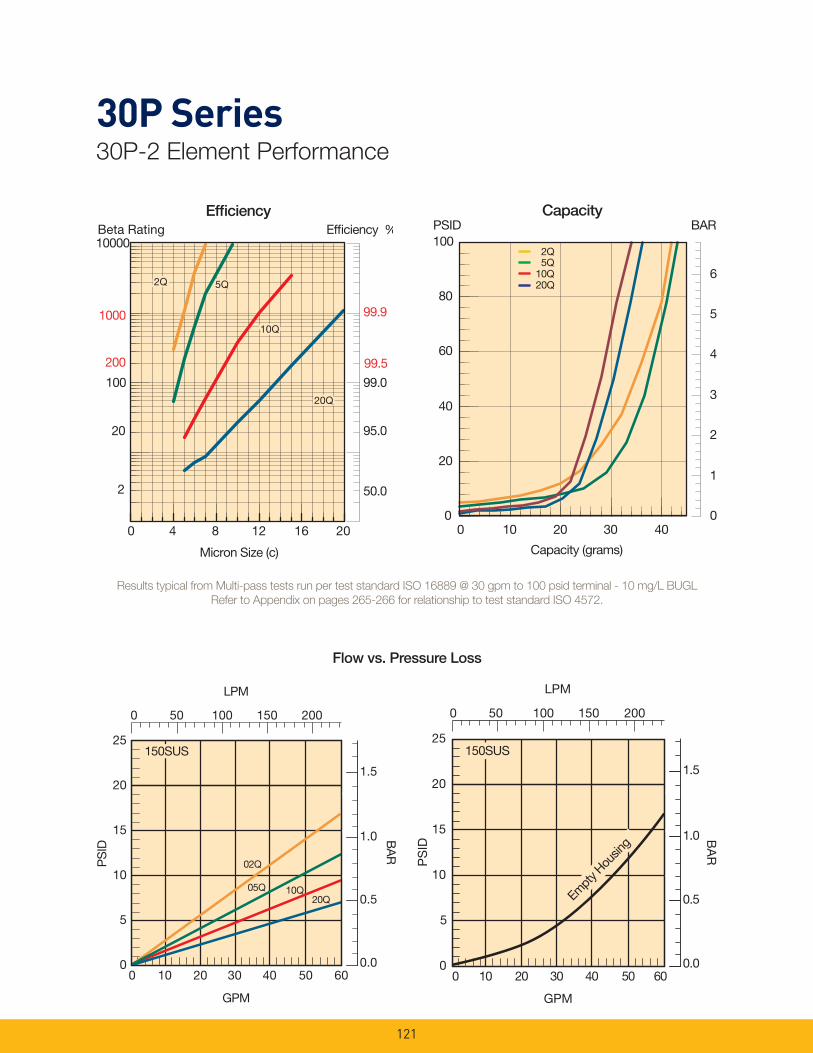
30P Series30P-2 Element Performance
121
Flow vs. Pressure Loss
Results typical from Multi-pass tests run per test standard ISO 16889 @ 30 gpm to 100 psid terminal - 10 mg/L BUGL
Refer to Appendix on pages 265-266 for relationship to test standard ISO 4572.
Efficiency %Efficiency
Beta Rating
1000
10000
99.9
99.5
99.0100
200
20
2 50.0
95.0
Micron Size (c)
2Q
10Q
20Q
2Q
10Q
20Q
2Q
10Q
20Q
5Q5Q
0 4 8 12 16 200
20
40
60
80
100
0
1
2
3
4
5
6
0 10 20 30 40
Capacity (grams)
PSID BARCapacity
2Q5Q
10Q20Q
25
20
15
10
5
0
LPM
PS
ID
GPM
1.5
1.0
0.5
0.0
BA
R
02Q
20Q05Q
150SUS
10Q
0 10 20 30 40 50 60
0 50 100 150 200
0 10 20 30 40 50 60
25
20
15
10
5
0
LPM
PS
ID
GPM
1.5
1.0
0.5
0.0
BA
R
150SUS
Empt
y Hou
sing
0 50 100 150 200

15P SeriesSpecifi cations
122
Pressure Ratings:Maximum Allowable Operating Pressure (MAOP): 3000 psi (206.9 bar)Rated Fatigue Pressure: 2000 psi (138 bar)Design Safety Factor: 3:1
Operating Temperatures:Buna: -40°F (-40°C) to 225°F (107°C) Fluorocarbon: -15°F (-26°C) to 275°F (135°C)
Element Collapse Rating:Standard- 350 psid (24.1 bar)“H” Option- 2000 psid (138 bar)“X” Option- 3000 psid (206.9 bar)
Materials:Bowl: impacted aluminum (anodized 6061-T6)Head: extruded aluminum (anodized 6061-T6)Bypass: nylon
Element Condition Indicators:Visual (optional) 360° green/ redElectrical/ Visual (optional) 5A @ 240VAC, 3A @ 28VDCElectrical-heavy duty (optional) .25A (resistive) MAX 5 watts 12 to 28 VDC & 110 to 175 VAC
Color Coding: White (common)Black (normally open)Blue (normally closed)
Weights (approximate):15P-1 3.5 lb. ( 1.6 kg.)15P-2 4.6 lb. ( 2.1 kg.)
Linear Measure: millimeterinch
Torque 55-70 Ft Lbs
173.5±.2. 36.83±.09
15P-1
Optional 7/16-20 SAE-4Drain PortTorque 15-20 Ft Lbs
Electrical/ Visual Indicator
Dia.
23.0.91
46.01.81
50.51.99
79.43.13
79.4±.133.125±.005
6.22.25
6.8±.13.266±.005
62.52.46
21.8.86
25.41.000
250.49.86
15P-2
268.7±.2. 310.58±.09
Torque 30-35 Ft Lbs
Bottom View
64.32.53
23.9.94
50.82.00
MinimumCartridge Removal
Clearance
Max61.02.4061.0
2.40
Max
42.41.67
Rotates 360
Visual Indicator
¾ SAE-12 (1-1/16-12 UN-2B)Straight Thd Boss Port Torque 79-90 Ft Lbs(Ref to SAE J-514)
155.36.11
101.64.00
15P-2
15P-1
87.03.43
Max59.22.33
Plugs Supplied WithBypass Only
Outlet.69 Dia.2-117 O-ring Boss
Inlet.69 Dia.2-117 O-ring Boss
15.8.63
31.71.25 .344 Thru
40.11.58
31.71.25
44.41.75
16.3.64
88.93.50
Top View
Manifold
Outlet
2 Plcs
2 Plcs
E3
Drawings are for reference only. Contact factory for current version.
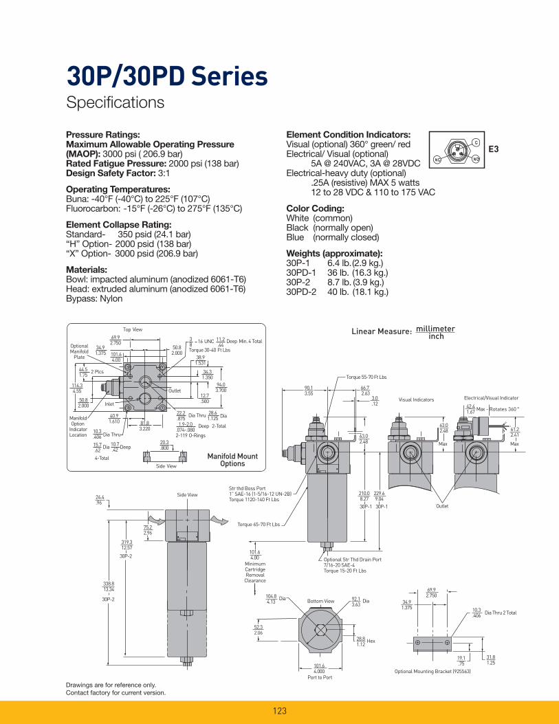
30P/30PD SeriesSpecifi cations
123
Pressure Ratings:Maximum Allowable Operating Pressure (MAOP): 3000 psi ( 206.9 bar)Rated Fatigue Pressure: 2000 psi (138 bar)Design Safety Factor: 3:1
Operating Temperatures:Buna: -40°F (-40°C) to 225°F (107°C) Fluorocarbon: -15°F (-26°C) to 275°F (135°C)
Element Collapse Rating:Standard- 350 psid (24.1 bar)“H” Option- 2000 psid (138 bar)“X” Option- 3000 psid (206.9 bar)
Materials:Bowl: impacted aluminum (anodized 6061-T6)Head: extruded aluminum (anodized 6061-T6)Bypass: Nylon
Element Condition Indicators:Visual (optional) 360° green/ redElectrical/ Visual (optional) 5A @ 240VAC, 3A @ 28VDCElectrical-heavy duty (optional) .25A (resistive) MAX 5 watts 12 to 28 VDC & 110 to 175 VAC
Color Coding:White (common)Black (normally open)Blue (normally closed)
Weights (approximate):30P-1 6.4 lb. (2.9 kg.)30PD-1 36 lb. (16.3 kg.)30P-2 8.7 lb. (3.9 kg.)30PD-2 40 lb. (18.1 kg.)
Linear Measure: millimeterinch
Torque 55-70 Ft Lbs
90.13.55
75.22.96
319.312.57
30P-2
Rotates 360
229.69.04
MaxMax
63.02.48 61.2
2.41
42.41.67
Max -
66.72.63
3.0.12
101.64.00
30P-1 30P-1
210.08.27
63.02.48
52.32.06
104.84.13
Dia
101.64.000
28.81.12
Hex
92.13.63
Dia
10.3.406
31.81.25
69.92.750
34.91.375
Dia Thru 2 Total
19.1.75
338.813.34
30P-2
24.4.96
Outlet
Port to PortOptional Mounting Bracket (925563)
Bottom View
MinimumCartridgeRemoval
Clearance
Optional Str Thd Drain Port7/16-20 SAE-4Torque 15-20 Ft Lbs
Side View
Torque 65-70 Ft Lbs
Str thd Boss Port1” SAE-16 (1-5/16-12 UN-2B)Torque 1120-140 Ft Lbs
Visual Indicators Electrical/Visual Indicator
94.03.700
34.31.350
12.7.500
28.61.125
22.2.875
Dia Thru Dia
Deep 2-Total1.9-2.0.074-.0802-119 O-Rings
Dia
10.3.406 Dia Thru
15.7.62
10.7.42
2 Plcs
ManifoldOption
IndicatorLocation
101.64.00
34.91.375
44.51.75
114.34.55
40.91.610 81.8
3.220
Inlet50.82.000
69.92.750
50.82.000
38.91.531
Outlet
38
16 UNC
Torque 30-40 Ft Lbs
11.2.44
Top View
Deep
4-Total
Deep Min. 4 Total
20.3.800
Side View
OptionalManifold
Plate
Manifold MountOptions
E3
Drawings are for reference only. Contact factory for current version.
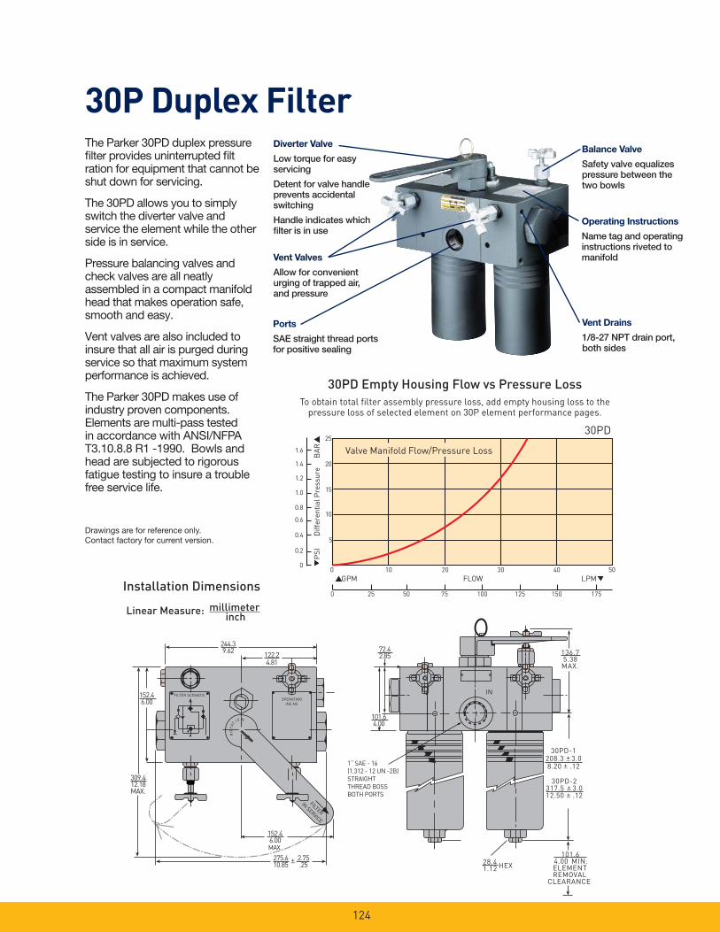
30P Duplex Filter
136.75.38MAX.
RO
TA
T
IO N
30PD-1208.3 3.08.20 .12
122.24.81
152.46.00
309.412.18MAX.
275.610.85
152.46.00MAX.
244.39.62
28.41.12
101.64.00 MIN.ELEMENTREMOVAL
CLEARANCE
30PD-2317.5 3.012.50 .12
IN
101.64.00
72.42.85
2.75.25 HEX
FILTER SCEMATICOPERATING
INS NS
FILTER
IN SERVICE
1“ SAE - 16(1.312 - 12 UN -2B)STRAIGHTTHREAD BOSSBOTH PORTS
30PD Empty Housing Flow vs Pressure Loss
Installation Dimensions
The Parker 30PD duplex pressure fi lter provides uninterrupted fi ltration for equipment that cannot be shut down for servicing.
The 30PD allows you to simply switch the diverter valve and service the element while the other side is in service.
Pressure balancing valves and check valves are all neatly as sembled in a compact manifold head that makes operation safe, smooth and easy.
Vent valves are also included to insure that all air is purged during service so that maximum system performance is achieved.
The Parker 30PD makes use of industry proven components. Elements are multi-pass tested in accordance with ANSI/NFPA T3.10.8.8 R1 -1990. Bowls and head are subjected to rigorous fatigue testing to insure a trouble free service life.
To obtain total fi lter assembly pressure loss, add empty housing loss to the pressure loss of selected element on 30P element perfor mance pages.
Valve Manifold Flow/Pressure Loss
30PD
GPM FLOW LPM
5
10
15
20
25
1.6
1.4
1.2
1.0
0.8
0.6
0.4
0.2
0
PS
IB
AR
Dif
fere
nti
al
Pre
ssu
re
0 25 50 75 100 125 150 175
0 10 20 30 40 50
Balance Valve
Safety valve equalizes pressure between the two bowls
Operating Instructions
Name tag and operating instructions riveted to manifold
Vent Drains
1/8-27 NPT drain port, both sides
Diverter Valve
Low torque for easy servicing
Detent for valve handle prevents accidental switching
Handle indicates which fi lter is in use
Ports
SAE straight thread ports for positive sealing
Vent Valves
Allow for convenient urging of trapped air, and pressure
Linear Measure: millimeterinch
Drawings are for reference only. Contact factory for current version.
124
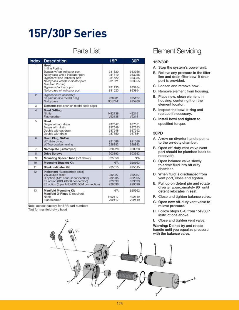
12
8
1
10 87 1 2
3
3
11
7
45 6
6
5
4
15P/30P Series
Note: consult factory for EPR part numbers*Not for manifold-style head
Element Servicing
15P/30P
A. Stop the system’s power unit.
B. Relieve any pressure in the fi lter line and drain fi lter bowl if drain port is provided.
C. Loosen and remove bowl.
D. Remove element from housing.
E. Place new, clean element in housing, centering it on the element locator.
F. Inspect the bowl o-ring and replace if necessary.
G. Install bowl and tighten to specifi ed torque.
30PD
A. Arrow on diverter handle points to the on-duty chamber.
B. Open off-duty vent valve (vent port should be plumbed back to reservoir).
C. Open balance valve slowly to admit fl uid into off duty chamber.
D. When fl uid is discharged from vent port, close and tighten.
E. Pull up on detent pin and rotate diverter approximately 90° until detent relocates in seat.
F. Close and tighten balance valve.
G. Open new off-duty vent valve to relieve pressure.
H. Follow steps C-G from 15P/30P instructions above.
I. Close and tighten vent valve.
Warning: Do not try and rotate handle until you equalize pressure with the balance valve.
Index Description 15P 30P 1 Head In-line Porting Bypass w/top indicator port 931520 933956 No bypass w/top indicator port 931519 933956 Bypass w/side indicator port 931522 933955 No bypass w/side indicator port 931521 933955 Manifold Porting Bypass w/indcator port 931135 933954 No bypass w/ indicator port 931523 933954
2 Bypass Valve Assembly 50 psid (in-line model only) 928981 925127 No bypass 935744* 925209
3 Elements (see chart on model code page)
4 Bowl O-Ring Nitrile N92138 N92151 Fluorocarbon V92138 V92151
5 Bowl Single without drain 937547 937551 Single with drain 937549 937553 Double without drain 937548 937552 Double with drain 937550 937554
6 Drain Plug, SAE-4 W/nitrile o-ring 921088 921088 W/fl uorocarbon o-ring 928882 928882
7 Nameplate (unstamped) 920928 920928
8 Drive Screws 903393 903393
9 Mounting Spacer Tube (not shown) 925650 N/A
10 Mounting Bracket Kit N/A 925563
11 Blank Indicator Kit 925515 925515
12 Indicators (fl uorocarbon seals) Visual auto reset 932027 932027 H option (1/2” conduit connection) 932905 932905 E2 option (DIN 43650 connection) 929599 929599 E3 option (3 pin ANSI/B93.55M connection) 929596 929596
13 Manifold Mounting Kit N/A 925562 Manifold O-Rings (2 required) Nitrile N92117 N92119 Fluorocarbon V92117 V92119
Parts List
125
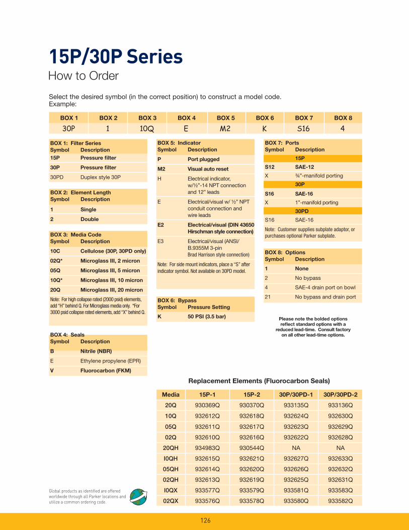
126
Select the desired symbol (in the correct position) to construct a model code. Example:
15P/30P SeriesHow to Order
BOX 1 BOX 2 BOX 3 BOX 4 BOX 5 BOX 6 BOX 7 BOX 8
30P 1 10Q E M2 K S16 4
BOX 1: Filter Series
Symbol Description
15P Pressure fi lter
30P Pressure fi lter
30PD Duplex style 30P
BOX 5: Indicator
Symbol Description
P Port plugged
M2 Visual auto reset
H Electrical indicator, w/½”-14 NPT connection and 12” leads
E Electrical/visual w/ ½” NPT conduit connection and wire leads
E2 Electrical/visual (DIN 43650
Hirschman style connection)
E3 Electrical/visual (ANSI/ B.9355M 3-pin Brad Harrison style connection)
Note: For side mount indicators, place a “S” after indicator symbol. Not available on 30PD model.
BOX 4: Seals
Symbol Description
B Nitrile (NBR)
E Ethylene propylene (EPR)
V Fluorocarbon (FKM)
BOX 8: Options
Symbol Description
1 None
2 No bypass
4 SAE-4 drain port on bowl
21 No bypass and drain port
BOX 2: Element Length
Symbol Description
1 Single
2 Double
BOX 3: Media Code
Symbol Description
10C Cellulose (30P, 30PD only)
02Q* Microglass III, 2 micron
05Q Microglass III, 5 micron
10Q* Microglass III, 10 micron
20Q Microglass III, 20 micron
Note: For high collapse rated (2000 psid) elements, add “H” behind Q. For Microglass media only. *For 3000 psid collapse rated elements, add “X” behind Q.
Please note the bolded options
refl ect standard options with a
reduced lead-time. Consult factory
on all other lead-time options.
BOX 6: Bypass
Symbol Pressure Setting
K 50 PSI (3.5 bar)
BOX 7: Ports
Symbol Description
15P
S12 SAE-12
X ¾”-manifold porting
30P
S16 SAE-16
X 1”-manifold porting
30PD
S16 SAE-16
Note: Customer supplies subplate adaptor, or purchases optional Parker subplate.
Replacement Elements (Fluorocarbon Seals)
Global products as identifi ed are offered worldwide through all Parker locations and utilize a common ordering code.
Media 15P-1 15P-2 30P/30PD-1 30P/30PD-2
20Q 930369Q 930370Q 933135Q 933136Q
10Q 932612Q 932618Q 932624Q 932630Q
05Q 932611Q 932617Q 932623Q 932629Q
02Q 932610Q 932616Q 932622Q 932628Q
20QH 934983Q 930544Q NA NA
I0QH 932615Q 932621Q 932627Q 932633Q
05QH 932614Q 932620Q 932626Q 932632Q
02QH 932613Q 932619Q 932625Q 932631Q
I0QX 933577Q 933579Q 933581Q 933583Q
02QX 933576Q 933578Q 933580Q 933582Q
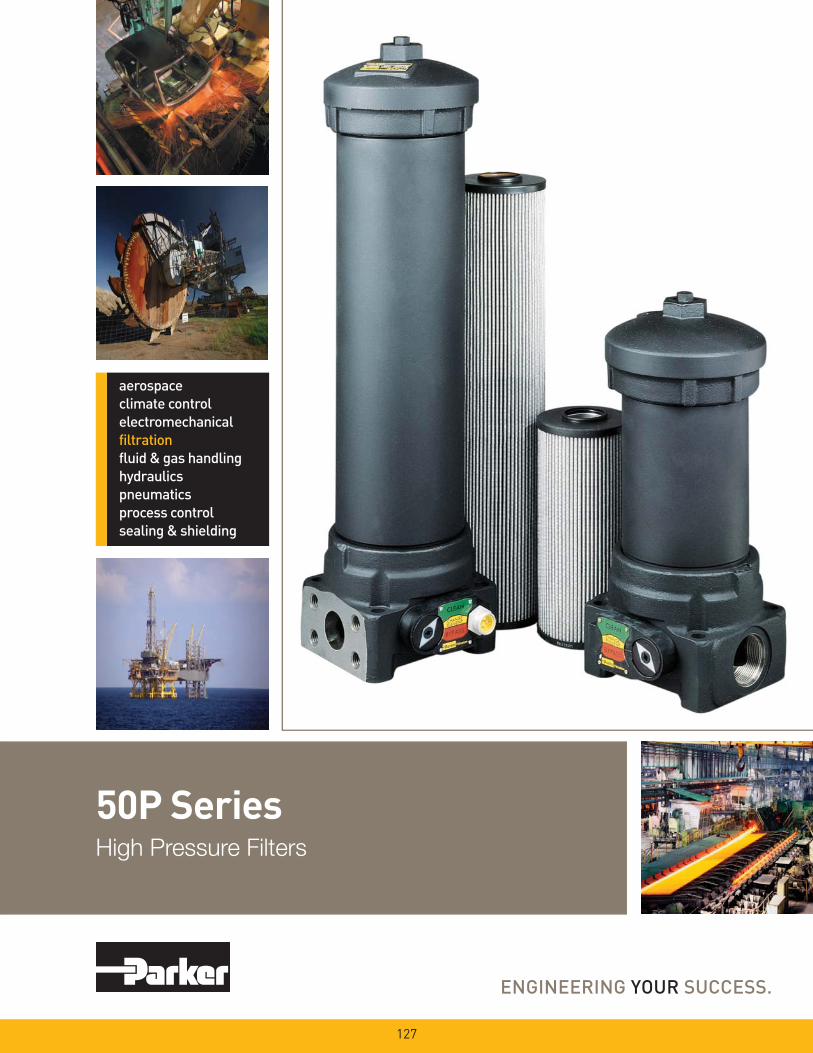
50P SeriesHigh Pressure Filters
127

128
50P SeriesApplications
Applications for 50P series fi lters
- Automotive specifi ed equipment
- Hydrostatic transmission circuits
- Servo and proportional controls
- Offshore drilling rigs
- Mining equipment
- Power units
The design objective for all Parker fi lters is to achieve a sensible balance between cost and performance. We use state of the art techno1ogy to arrive at innovative yet practical designs. Designs which are cost effective for OEM’s and users alike.
The 50P series allows you to customize each fi lter to closely match your needs. Choose the options which best fi t your application. No need to waste money on features you don’t need.
The 50P series fi lters are base mounted, which provides several possible advan tages. The bowl up mounting makes servicing the elements quick and easy. Simply remove the top cover to access the element. A drain port is provided to allow oil be removed from fi lter prior to element servicing. This design reduces the possibility of oil spillage and injury to maintenance personnel.
The 50P series has optional manifold porting for space saving design that re duces the number of fi ttings and potential leak points. The porting is also designed to match the installation of many other manufacturers. Most important, the 50P series meets the SAE HF4 automotive standard.
Vent Plug- Purge all air from
fi lter assembly
- Improves system performance
Bowl- Single or double
lengthHead- Ductile iron
construction- SAE or manifold ports
- Meets SAE HF4 automotive specifi cation
Drain Plug(not visible)- Drain oil for
easy service
Indicators- Visual or
electrical/visual
- Several connector options
Cover- Durable ductile iron
- Top service elements
- No oil spills during service
Bypass(not visible)- Cartridge style
- Precision matched assemblies

129
50P SeriesFeatures
O-Ring Seal- Positive sealing for optimum
ele ment effi ciency
Plastic End Caps - Excellent corrosion
pro tection
- Laser marked for clear long lasting identifi cation
Microglass III Media- Multi-layer for high capacity and
high effi ciency
- Four different micron sizes available
- Wire reinforced to prevent pleat bunching
Spiral Support Cylinders(Not Visible)- High strength consistent support
- Continuous length eliminates leak points and increasessurface area
Meets SAE HF4 specifi caton for automotive uses
Feature Advantage Benefi t
• Base mounted fi lter • No brackets required for installation • Reduced installation costs
• Top access cover • Remove element from top • No oil mess
• Lighter then removing entire bowl
• Visual and electrical indicators • Know exactly when to service elements
• Drain port • Drain all oil from assembly prior • Eliminates cross contamination to servicing
• Vent port • Purges all trapped air in fi lter • Get the maximum performance from elements
• Prevents a “spongy” system
• Multipass tested elements • Element performance backed • Elements selected will have (per ANSI/NFPA T3.10.8.8 R1-1990) by recognized test standards consistent performance levels
• Microglass III elements • Multi-layer media • High capacity with high effi ciency
• Wire reinforced pleats • No performance loss from pleat bunching
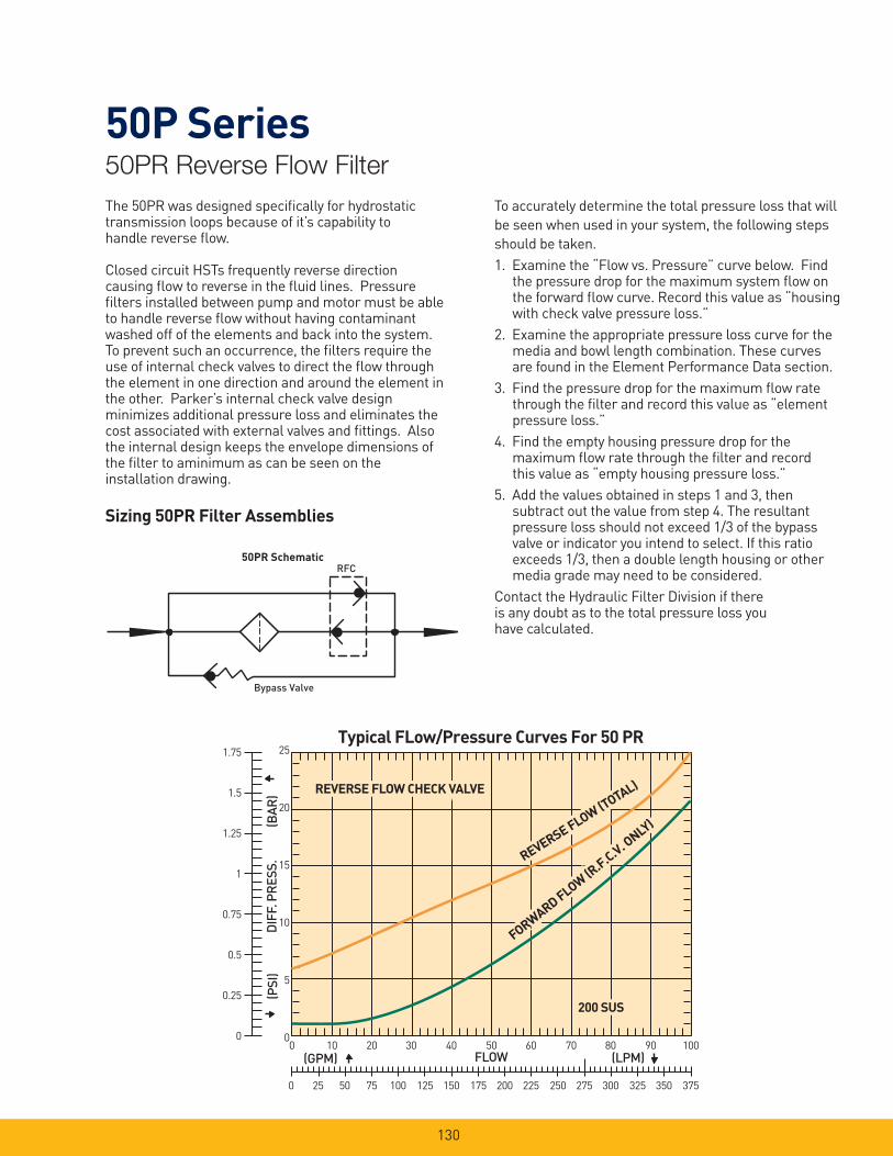
130
50P Series50PR Reverse Flow Filter
The 50PR was designed specifi cally for hydrostatic transmission loops because of it’s capability to handle reverse fl ow.
Closed circuit HSTs frequently reverse direction causing fl ow to reverse in the fl uid lines. Pressure fi lters installed between pump and motor must be able to handle reverse fl ow without having contaminant washed off of the elements and back into the system. To prevent such an occurrence, the fi lters require the use of internal check valves to direct the fl ow through the element in one direction and around the element in the other. Parker’s internal check valve design minimizes additional pressure loss and eliminates the cost associated with external valves and fi ttings. Also the inter nal design keeps the envelope dimensions of the fi lter to aminimum as can be seen on the installation drawing.
Sizing 50PR Filter Assemblies
To accurately determine the total pressure loss that will
be seen when used in your system, the following steps
should be taken.
1. Examine the “Flow vs. Pressure” curve below. Find the pressure drop for the maximum system fl ow on the forward fl ow curve. Record this value as “housing with check valve pressure loss.”
2. Examine the appropriate pressure loss curve for the media and bowl length combination. These curves are found in the Element Performance Data section.
3. Find the pressure drop for the maximum fl ow rate through the fi lter and record this value as “element pressure loss.”
4. Find the empty housing pressure drop for the maximum fl ow rate through the fi lter and record this value as “empty housing pressure loss.”
5. Add the values obtained in steps 1 and 3, then subtract out the value from step 4. The resultant pressure loss should not exceed 1/3 of the bypass valve or indicator you intend to select. If this ratio exceeds 1/3, then a double length housing or other media grade may need to be considered.
Contact the Hydraulic Filter Division if there is any doubt as to the total pressure loss you have calculated.
Bypass Valve
50PR SchematicRFC
Typical FLow/Pressure Curves For 50 PR1.75
1.5
1.25
1
0.75
0.5
0.25
0
25
20
15
10
5
0
(BAR
)D
IFF.
PR
ESS.
(PSI
)
0 10 20 30 40 50 60 70 80 90 100(GPM) FLOW (LPM)
0 25 50 75 100 125 150 175 200 225 250 275 300 325 350 375
200 SUS200 SUS200 SUS
FORWARD FLOW (R.F.C.V. O
NLY)
FORWARD FLOW (R.F.C.V. O
NLY)
FORWARD FLOW (R.F.C.V. O
NLY)
REVERSE FLOW (TOTAL)
REVERSE FLOW (TOTAL)
REVERSE FLOW (TOTAL)REVERSE FLOW CHECK VALVEREVERSE FLOW CHECK VALVEREVERSE FLOW CHECK VALVE
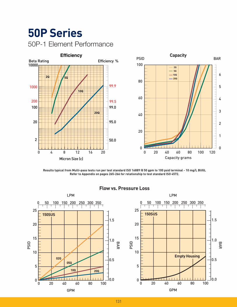
131
50P Series50P-1 Element Performance
Efficiency %Efficiency
Beta Rating
1000
10000
99.9
99.599.0100
200
20
2 50.0
95.0
Micron Size (c)
2Q
10Q
20Q
2Q
10Q
20Q
2Q
10Q
20Q
5Q5Q
0 4 8 12 16 20
LPM
25
20
15
10
5
0
02Q
20Q10Q
PSID
GPM
1.5
1.0
0.5
0.0
BA
R
150SUS
05Q
0 50 100 150 200 250 300 350
0 20 40 60 80 100
LPM
25
20
15
10
5
0
PSID
GPM
1.5
1.0
0.5
0.0
BAR
150SUS
Empty Housing
0 50 100 150 200 250 300 350
0 20 40 60 80 100
Flow vs. Pressure Loss
0
20
40
60
80
100
0
1
2
3
4
5
6
Capacity grams
PSID BAR Capacity
5Q
2Q
20Q
10Q
0 20 40 60 80 100 120
Results typical from Multi-pass tests run per test standard ISO 16889 @ 50 gpm to 100 psid terminal - 10 mg/L BUGL
Refer to Appendix on pages 265-266 for relationship to test standard ISO 4572.

132
50P Series50P-2 Element Performance
Efficiency %Efficiency
Beta Rating
1000
10000
99.9
99.599.0100
200
20
2 50.0
95.0
Micron Size (c)
2Q
10Q
20Q
2Q
10Q
20Q
2Q
10Q
20Q
5Q5Q
0 4 8 12 16 20
25
20
15
10
5
0
02Q
20Q
10Q
05Q
LPM
PSID
GPM
1.5
1.0
0.5
0.0
BAR
150SUS
0 100 200 300 400 500
0 30 60 90 120 150
25
20
15
10
5
0
LPM
PSID
GPM
1.5
1.0
0.5
0.0
BAR
150SUS
Empty Housing
0 100 200 300 400 500
0 30 60 90 120 150
0
1
2
3
4
5
6
Capacity grams
0
20
40
60
80
100 PSID BAR
Capacity
20Q10Q
2Q5Q
0 50 100 150 200 250 300
Flow vs. Pressure Loss
Results typical from Multi-pass tests run per test standard ISO 16889 @ 80 gpm to 100 psid terminal - 10 mg/L BUGL
Refer to Appendix on pages 265-266 for relationship to test standard ISO 4572.

133
50P Series50P-3 Element Performance
Efficiency % Efficiency
Beta Rating
1000
10000
99.9
99.5 99.0 100
200
20
2 50.0
95.0
Micron Size (c)
0 4 8 12 16 20
2Q2Q2Q5Q5Q5Q
20Q20Q20Q
10Q10Q10Q
LPM
25
20
15
10
5
0
02Q
20Q
10Q
PSID
GPM
1.5
1.0
0.5
0.0
BA
R
150SUS
05Q
0 100 200 300 400 500
0 30 60 90 120 150
LPM
25
20
15
10
5
0
PSID
GPM
1.5
1.0
0.5
0.0
BAR
150SUS
0 20 40 60 80 100
0 100 200 300 400 500
Empty Housing
Flow vs. Pressure Loss
0
20
40
60
80
100
0
1
2
3
4
5
6
Capacity grams
PSID BAR Capacity
5Q
2Q
20Q
10Q
0 50 100 150 200 250 300 350 400
Results typical from Multi-pass tests run per test standard ISO 16889 @ 80 gpm to 100 psid terminal - 10 mg/L BUGL
Refer to Appendix on pages 265-266 for relationship to test standard ISO 4572.
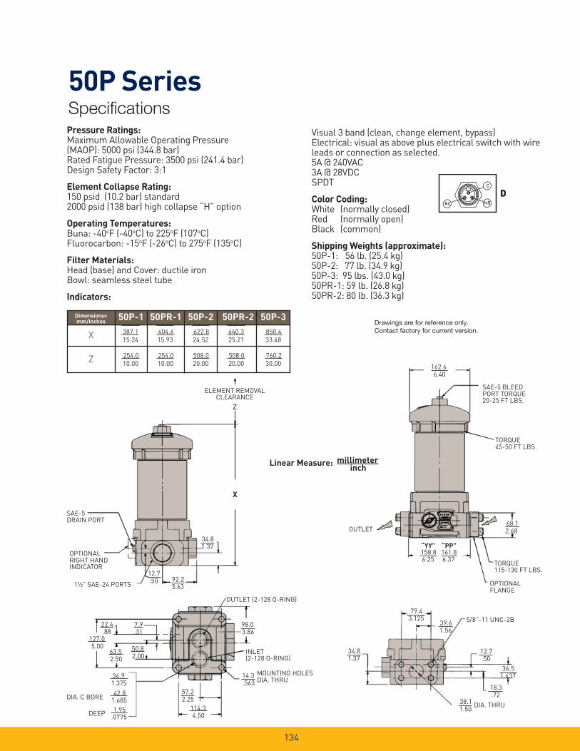
134
50P SeriesSpecifi cations
162.66.40
68.1
SAE-5 BLEED PORT TORQUE 20-25 FT LBS.
TORQUE 45-50 FT LBS.
TORQUE 115-130 FT LBS.
OPTIONAL FLANGE
OUTLET
158.86.25
161.86.37
“YY” “PP”
2.68
Pressure Ratings:Maximum Allowable Operating Pressure (MAOP): 5000 psi (344.8 bar)Rated Fatigue Pressure: 3500 psi (241.4 bar)Design Safety Factor: 3:1
Element Collapse Rating: 150 psid (10.2 bar) standard2000 psid (138 bar) high collapse “H” option
Operating Temperatures:Buna: -40oF (-40oC) to 225oF (107oC)Fluorocarbon: -15oF (-26oC) to 275oF (135oC)
Filter Materials:Head (base) and Cover: ductile ironBowl: seamless steel tube
Indicators:
Visual 3 band (clean, change element, bypass)Electrical: visual as above plus electrical switch with wire leads or connection as selected.5A @ 240VAC3A @ 28VDCSPDT
Color Coding:White (normally closed)Red (normally open)Black (common)
Shipping Weights (approximate):50P-1: 56 lb. (25.4 kg)50P-2: 77 lb. (34.9 kg)50P-3: 95 lbs. (43.0 kg)50PR-1: 59 lb. (26.8 kg)50PR-2: 80 lb. (36.3 kg)
7.9
127.05.00
34.9
42.8
1.95
57.2
114.3
98.03.86
4.50
14.3.563
2.25
.0775
1.685
1.375
.31
50.82.00
63.52.50
Linear Measure: millimeterinch
34.81.37
92.23.63
12.7.50
ELEMENT REMOVAL CLEARANCE
Z
SAE-5 DRAIN PORT
OPTIONAL RIGHT HAND INDICATOR
1½” SAE-24 PORTS
OUTLET (2-128 O-RING)
INLET (2-128 O-RING)
MOUNTING HOLES DIA. THRU
DEEP
DIA. C BORE
X
22.4.88
79.43.125
39.61.56
34.81.37
38.11.50
18.3.72
36.51.437
12.7.50
5/8”-11 UNC-2B
DIA. THRU
D
Drawings are for reference only. Contact factory for current version.
387.1
15.24
404.6
15.93
622.8
24.52
640.3
25.21
254.0
10.00
254.0
10.00
508.0
20.00
508.0
20.00
X
Z
50P-1 50PR-1 50P-2 50PR-2 50P-3Dimensions=mm/inches
850.4
33.48
760.2
30.00
387.1 404.6 622.8 640.3
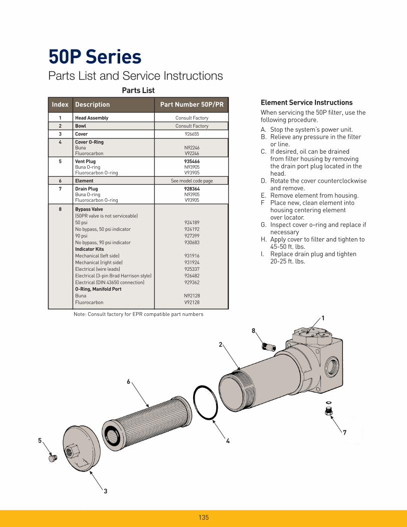
135
50P SeriesParts List and Service Instructions
Element Service Instructions
When servicing the 50P fi lter, use the following procedure.
A. Stop the system’s power unit.B. Relieve any pressure in the fi lter
or line.C. If desired, oil can be drained
from fi lter housing by removing the drain port plug located in the head.
D. Rotate the cover counter clockwise and remove.
E. Remove element from housing.F Place new, clean element into
housing centering element over locator.
G. Inspect cover o-ring and replace if necessary
H. Apply cover to fi lter and tighten to 45-50 ft. lbs.
I. Replace drain plug and tighten 20-25 ft. lbs.
Parts List
Index Description Part Number 50P/PR
1 Head Assembly Consult Factory
2 Bowl Consult Factory
3 Cover 926655
4 Cover O-Ring
Buna N92246 Fluorocarbon V92246
5 Vent Plug 935466
Buna O-ring N93905 Fluorocarbon O-ring V93905
6 Element See model code page
7 Drain Plug 928364
Buna O-ring N93905 Fluorocarbon O-ring V93905
8 Bypass Valve
(50PR valve is not serviceable)
50 psi 924189
No bypass, 50 psi indicator 924192
90 psi 927399
No bypass, 90 psi indicator 930683
Indicator Kits
Mechanical (left side) 931916
Mechanical (right side) 931924
Electrical (wire leads) 925337
Electrical (3-pin Brad Harrison style) 926482
Electrical (DIN 43650 connection) 929362
O-Ring, Manifold Port
Buna N92128
Fluorocarbon V92128
Note: Consult factory for EPR compatible part numbers1
8
2
6
5
3
4
7
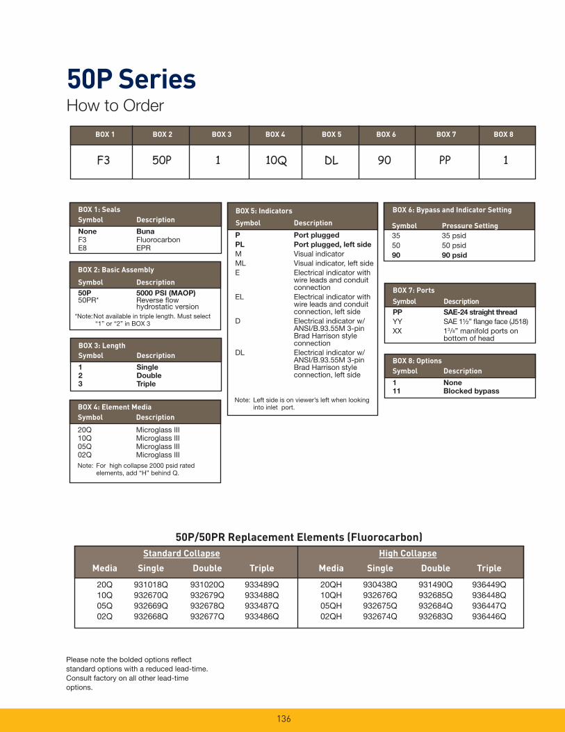
136
50P SeriesHow to Order
50P/50PR Replacement Elements (Fluorocarbon)
Standard Collapse High Collapse
Media Single Double Triple Media Single Double Triple
20Q 931018Q 931020Q 933489Q 20QH 930438Q 931490Q 936449Q 10Q 932670Q 932679Q 933488Q 10QH 932676Q 932685Q 936448Q 05Q 932669Q 932678Q 933487Q 05QH 932675Q 932684Q 936447Q 02Q 932668Q 932677Q 933486Q 02QH 932674Q 932683Q 936446Q
Please note the bolded options refl ect standard options with a reduced lead-time. Consult factory on all other lead-time options.
BOX 6: Bypass and Indicator Setting
BOX 2: Basic Assembly
Symbol Description
50P 5000 PSI (MAOP)50PR* Reverse fl ow hydrostatic version
BOX 3: Length
Symbol Description
1 Single
2 Double
3 Triple
Symbol Pressure Setting
35 35 psid50 50 psid90 90 psid
BOX 7: Ports
Symbol Description
PP SAE-24 straight thread
YY SAE 1½” fl ange face (J518)XX 13/8” manifold ports on bottom of head
BOX 8: Options
Symbol Description
1 None
11 Blocked bypass
BOX 1: Seals
Symbol Description
None Buna
F3 FluorocarbonE8 EPR
Symbol Description
P Port plugged
PL Port plugged, left side
M Visual indicatorML Visual indicator, left sideE Electrical indicator with
wire leads and conduit connection
EL Electrical indicator with wire leads and conduit connection, left side
D Electrical indicator w/ANSI/B.93.55M 3-pin Brad Harrison style connection
DL Electrical indicator w/ANSI/B.93.55M 3-pin Brad Harrison style connection, left side
BOX 5: Indicators
BOX 4: Element Media
Symbol Description
20Q Microglass III10Q Microglass III05Q Microglass III02Q Microglass IIINote: For high collapse 2000 psid rated elements, add “H” behind Q.
Note: Left side is on viewer’s left when looking into inlet port.
BOX 1 BOX 2 BOX 3 BOX 4 BOX 5 BOX 6 BOX 7 BOX 8
*Note: Not available in triple length. Must select “1” or “2” in BOX 3
F3 50P 1 10Q DL 90 PP 1
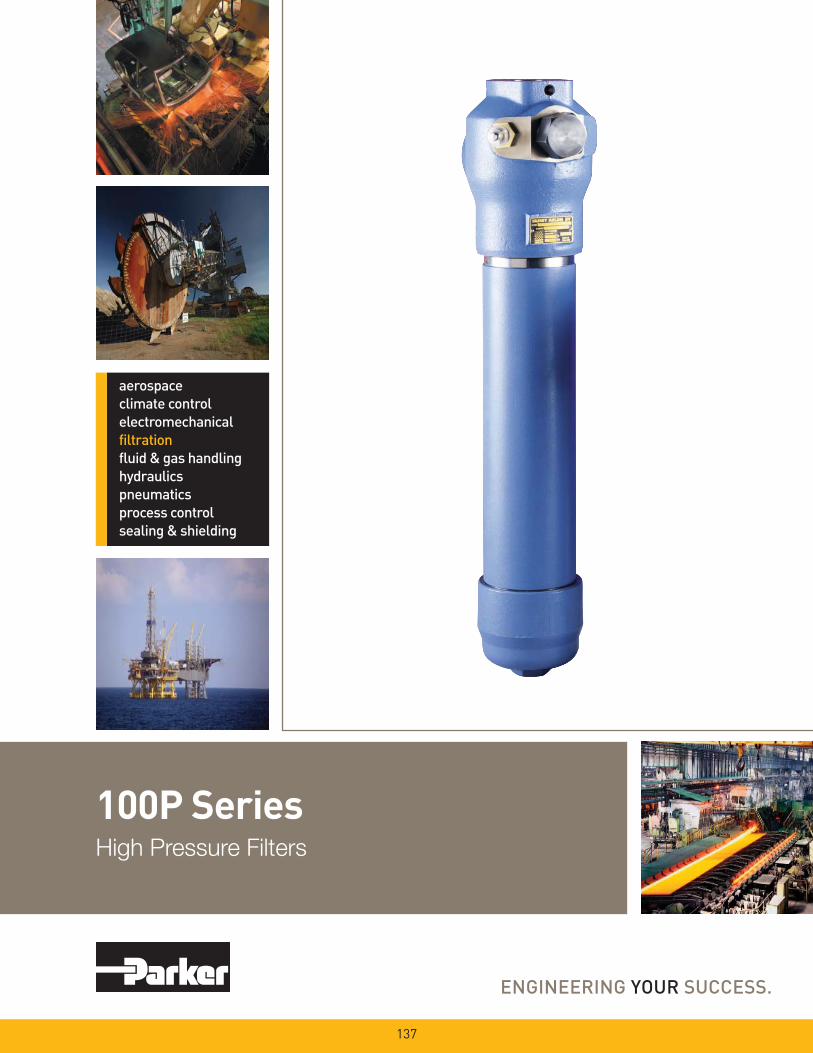
100P SeriesHigh Pressure Filters
137

138
100P SeriesApplications
Features/Applications for High Pressure Hydraulic Filters 100P Series
- Pressures to 6,000 PSI
- Flows to 265 GPM
- Microglass Elements 3 to 20 Micron
Specifi cations:
Flow Rating: 265 GPM
Operating Pressure: 6000 PSI
Proof Pressure: 9000 PSI
Burst Pressure: 12,000 PSI
Fatigue Pressure:0-4000-0 PSI@3,000,000 cycles
Bypass Setting: 100 PSID
Fluid Temperature: -40°F to +212°F
Constrution:
Head and Cap: Nodular Iron
Bowl: Seamless Steel Tube
Indicators: Brass
Elements: Consult Factory
Weight:
Length 1 -84 Lbs.
Length 2 -104 Lbs.
Electrical Ratings:
Hirschman Connector without Lamps:
E2 - 110 VAC, .5 Amp Ind., 2 Amp Res.
- 250 VAC, .5 Amp Ind., 2 Amp Res.
- 28 VDC, 1 Amp Ind., 2 Amp Res.
‘E2’
- 1½” and 2” Ports - SAE O-Ring or
Code 62 Flange
- Reverse Flow Option
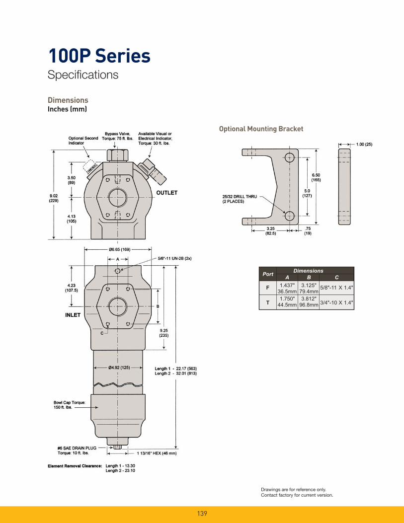
139
100P SeriesSpecifi cations
DimensionsInches (mm)
Optional Mounting Bracket
������������
� �
� ���� ����� � ���� � ��������� �����
����� �����
� ���� � ��������� ������
Drawings are for reference only. Contact factory for current version.
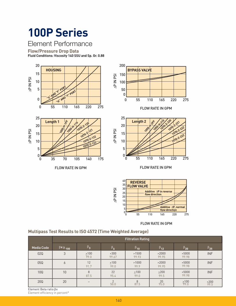
140
100P SeriesElement PerformanceFlow/Pressure Drop DataFluid Conditions: Viscosity 140 SSU and Sp. Gr. 0.88
Multipass Test Results to ISO 4572 (Time Weighted Average)
Media Code x > 100
3
6
10
12
20
25
02Q 3 >10099.0
>30099.67
>150099.93
>200099.95
>500099.98
INF
05Q 6 12
91.7
>100
99.0
>1000
99.9
>2000
99.95
>500099.98
INF
10Q 10 8
87.5
22
95.4
>100
99.0
>200
99.5
>500099.98
INF
20Q 20 – 250.0
887.5
2095.0
>10099.0
>20099.5
Filtration Rating
Element Beta ratio xElement effi ciency in percent*
Δ
HOUSINGHOUSING
“H“ AND “T” PORT
“H“ AND “T” PORT
“S“ AND “F” PORT
“S“ AND “F” PORT
20
15
10
5
0
0 55 110 165 220 275
P IN
PSI
Length 1Length 1
FLOW RATE IN GPM
0 35 70 105 140 175
10
5
15
20
1050
-H-1
FF
1050
-H-1
FF1050-H
-110
1050-H-1
10
1070-Z-120
1070-Z-120
1070-Z-121
1070-Z-121
1070-Z-122
1070-Z-122
1070-Z-1231070-Z-123Δ
25
0
P IN
PSI
BYPASS VALVEBYPASS VALVE
FLOW RATE IN GPM
200
0 55 110 165 220 275
500
100
150
Δ P IN
PSI
Length 2Length 2
Δ
0
P IN
PSI
0 55 110 165 220 275
5
10
15
20
25
FLOW RATE IN GPM
1070-Z-2
20
1070-Z-2
20
1070-Z-221
1070-Z-221
1070-Z-222
1070-Z-222
1070-Z-223
1070-Z-223
1050
-H-2
FF
1050
-H-2
FF1050-H
-210
1050-H-2
10
FLOW RATE IN GPM
403530
25201510
50
Δ P IN
PSI
REVERSEFLOW VALVE
Additive P in reverseflow direction
Δ
Additive P, normalflow direction
Δ
0 55 110 165 220 275

141
100P SeriesParts List
*Included in Seal Kit: 936063, Nitrile 936064, Fluorocarbon
†Included in Element Kit
‡To specify seal material, add the following suffi x to the part number: A Nitrile H Fluorocarbon
Options (Not Shown)
Part
Number Description
402904 Mounting Bracket, Includes (2) 5/8”-11 x 1-1/4” Hex Flange Bolts
3 Head
Description Part Number
1000-F, 1-1/2² SAE 6000 PSI Flange, Code 62 84.69.268.20
1000-T, 2² SAE 6000 PSI Flange, Code 62 84.69.268.22
4 Seals
Description Buna-N Viton
Bypass Assy/Plug Seal* N93924 V93924
Indicator to Head Seal* N72019 V72019
Actuator Dust Seal N72021
Adaptor to Head Seal* 81.10.150.15 81.10.152.15
Head/Bowl/Cap Seal* N92346 V92346
Head to Bowl Back-Up Ring FF3142
Element Seal N72141 V72141
Bowl Cap Seal* 81.10.150.86 81.10.152.86
Drain Plug Seal* N93906 V93906
5 Element Kit‡
Disposable All Fluids
Length 3 µm abs. 6 µm abs. 10 µm abs. 20 µm abs.
1 939060Q 939061Q 939062Q 939063Q
2 939064Q 939065Q 939066Q 939067Q
High Collapse Disposable (3000 psid)
Length 3 µm absolute 15 µm absolute
1 940737Q 940738Q
2 940741Q 940742Q
i
h
g
f
e
d
c
b
a
1 Indicators
Visual Electrical Sub-Assy Indicator Plug
6N50-2A 90.34.000.24 84.01.066.30
2 Electrical Actuator Assembly
Hirschmann Connector
Part Voltages
Code Number Available
E2 FF3468 28 VDC, 250 VAC Max.
Drawings are for reference only. Contact factory for current version.

142
100P SeriesHow to Order
Select the desired symbol (in the correct position) to construct a model code. Example:
BOX 1 BOX 2 BOX 3 BOX 4 BOX 5 BOX 6 BOX 7 BOX 8
100P 2 10Q B M2 M F32 1
BOX 1: Filter Series
Symbol Description
100P High Pressure fi lter
BOX 5: Indicator
Symbol Description
M2 Visual differential2
E2 Electrical differential2
BOX 4: Seals
Symbol Description
B Nitrile
V Fluorocarbon
BOX 8: Options
Symbol Description
1 None
3 Reverse fl ow valve (RFV)
TP Mounting bracket (including bolts)
3TP RFV & mounting bracket (including bolts)
BOX 2: Element Length
Symbol Description
2 Double
BOX 3: Media Code
Symbol Description
Standard Element
02Q Microglass III, 2 micron
05Q Microglass III, 5 micron
10Q Microglass III, 10 micron
20Q Microglass III, 20 micron
High Collapse Element
02QX Microglass III, 2 micron
10QX Microglass III, 10 micron
Notes:
1. Filters include the element you select
already installed.
2. Indicator setting is 73 psid (5,0 bar).
3. When the no bypass option is selected,
a high collapse element must also be
selected.
BOX 6: Bypass
Symbol Pressure Setting
M 100 PSID (7.0 bar)
X No bypass3
BOX 7: Ports
Symbol Description
F24 1-1/2” SAE fl ange, Code 62
F32 2” SAE fl ange, Code 62

143
World Pressure FiltersA New Standard in 7,000 psi Pressure Filters

144
WPF SeriesApplications
Together we can…
Preserve the environment. Minimize waste and promote energy effi ciency.
Achieve worldwide fi ltration solutions. Build global confi dence.
Redefi ne new limits. Forge ahead with advanced technology.
Keep contamination under control. Reduce maintenance costs.
Enhance total system reliability. Focus on customer satisfaction.
Reach optimum potential. Drill to greater depths.
…engineer your success.
Typical Applications
• Aircraft Ground Support
• Injection Molding
• Mining
• Mobile Ag
• Mobile Construction
• Oil & Gas Exploration
• Power Generation
• Primary Metals
• Refuse Trucks
Parker engineers have developed what soon will be the industry standard in high pressure hydraulic fi ltration. The new 7,000 psi WPF series incorporates many advanced features designed for one reason: to improve your bottom line.
There is no better high pressure fi lter available today for durability and performance. The reduction of your operating costs is our primary concern, and we are committed to contributing towards your success.
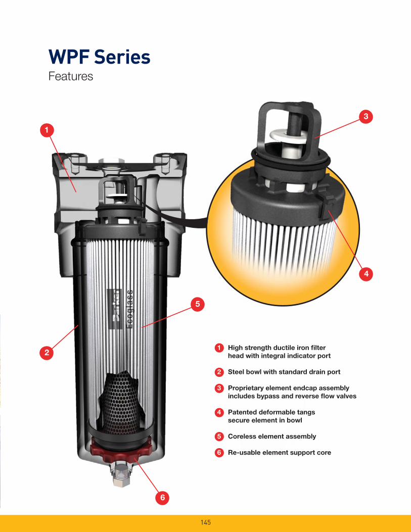
145
1
WPF SeriesFeatures
3
1 High strength ductile iron fi lter
head with integral indicator port
2 Steel bowl with standard drain port
3 Proprietary element endcap assembly
includes bypass and reverse fl ow valves
4 Patented deformable tangs
secure element in bowl
5 Coreless element assembly
6 Re-usable element support core
4
5
6
2
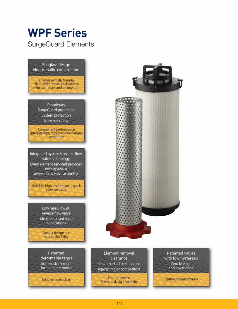
146
WPF SeriesSurgeGuard Elements
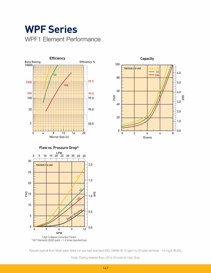
147
WPF SeriesWPF1 Element Performance
*High Collapse Correction Factor:
“QH” Elements (2000 psid) = 1.4 times reported loss
30
1.5
2.0
1.0
0.5
0.0
BAR
PSID
25
20
15
10
5
0
GPM
0 3 6 9 12
0 5 10 15 20 25 30 35 40 45
2Q5Q
10Q
Empty Housing
150 SUS (32 cSt)
LPM
Flow vs. Pressure Drop*
100
4.0
6.0
2.0
5.0
3.0
1.0
0.0
BAR
PSID
80
60
40
20
0
Grams
0 2 4 6 8
150 SUS (32 cSt)
Capacity
2Q5Q
10Q
Note: During reverse fl ow, ΔP is 20 psid at max. fl ow.
Results typical from Multi-pass tests run per test standard ISO 16889 @ 10 gpm to 50 psid terminal - 10 mg/L BUGL.
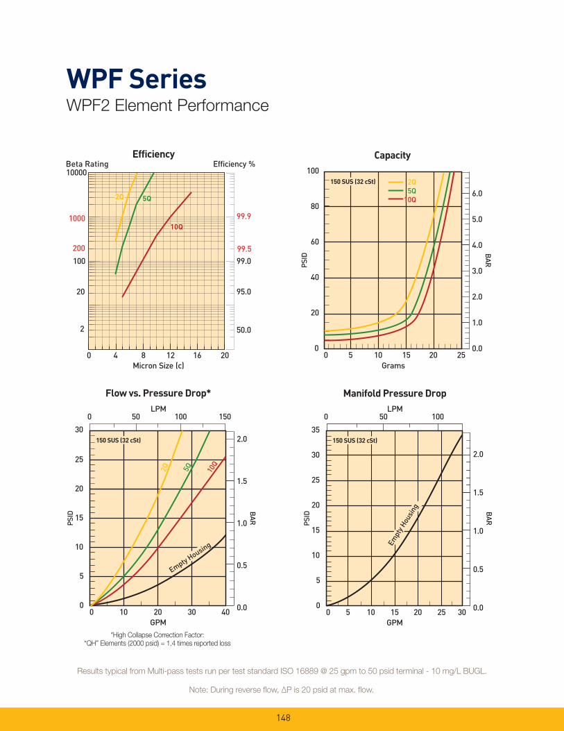
148
*High Collapse Correction Factor:
“QH” Elements (2000 psid) = 1.4 times reported loss
Note: During reverse fl ow, ΔP is 20 psid at max. fl ow.
Results typical from Multi-pass tests run per test standard ISO 16889 @ 25 gpm to 50 psid terminal - 10 mg/L BUGL.
WPF SeriesWPF2 Element Performance
30
1.5
2.0
1.0
0.5
0.0
BAR
PSID
25
20
15
10
5
0
GPM
LPM
0 10 20 30 40
0 50 100 150
2Q 5Q 10Q
Empty Housing
150 SUS (32 cSt)
Flow vs. Pressure Drop*
35
30
1.5
2.0
1.0
0.5
0.0
BAR
PSID
25
20
15
10
5
0
GPM
LPM
0 5 10 15 20 25 30
0 50 100
Empt
y Hou
sing
150 SUS (32 cSt)
Manifold Pressure Drop
100
4.0
6.0
2.0
5.0
3.0
1.0
0.0
BAR
PSID
80
60
40
20
0
Grams
0 5 10 15 20 25
150 SUS (32 cSt)
Capacity
2Q5Q
10Q
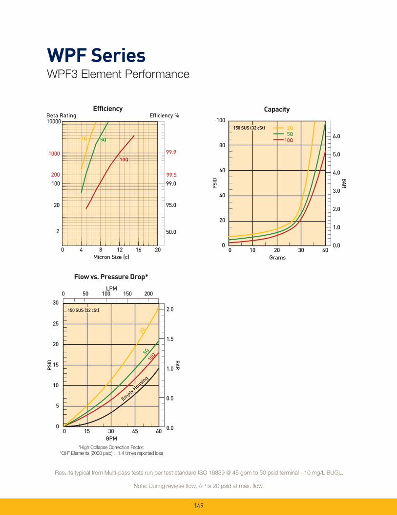
149
*High Collapse Correction Factor:
“QH” Elements (2000 psid) = 1.4 times reported loss
Note: During reverse fl ow, ΔP is 20 psid at max. fl ow.
Results typical from Multi-pass tests run per test standard ISO 16889 @ 45 gpm to 50 psid terminal - 10 mg/L BUGL.
WPF SeriesWPF3 Element Performance
30
1.5
2.0
1.0
0.5
0.0
BAR
PSID
25
20
15
10
5
0
GPM
LPM
0 15 30 45 60
2Q5Q
10Q
Empty Housing
150 SUS (32 cSt)
0 50 100 150 200
Flow vs. Pressure Drop*
100
4.0
6.0
2.0
5.0
3.0
1.0
0.0
BAR
PSID
80
60
40
20
0
Grams
0 10 20 30 40
150 SUS (32 cSt)
Capacity
2Q5Q
10Q
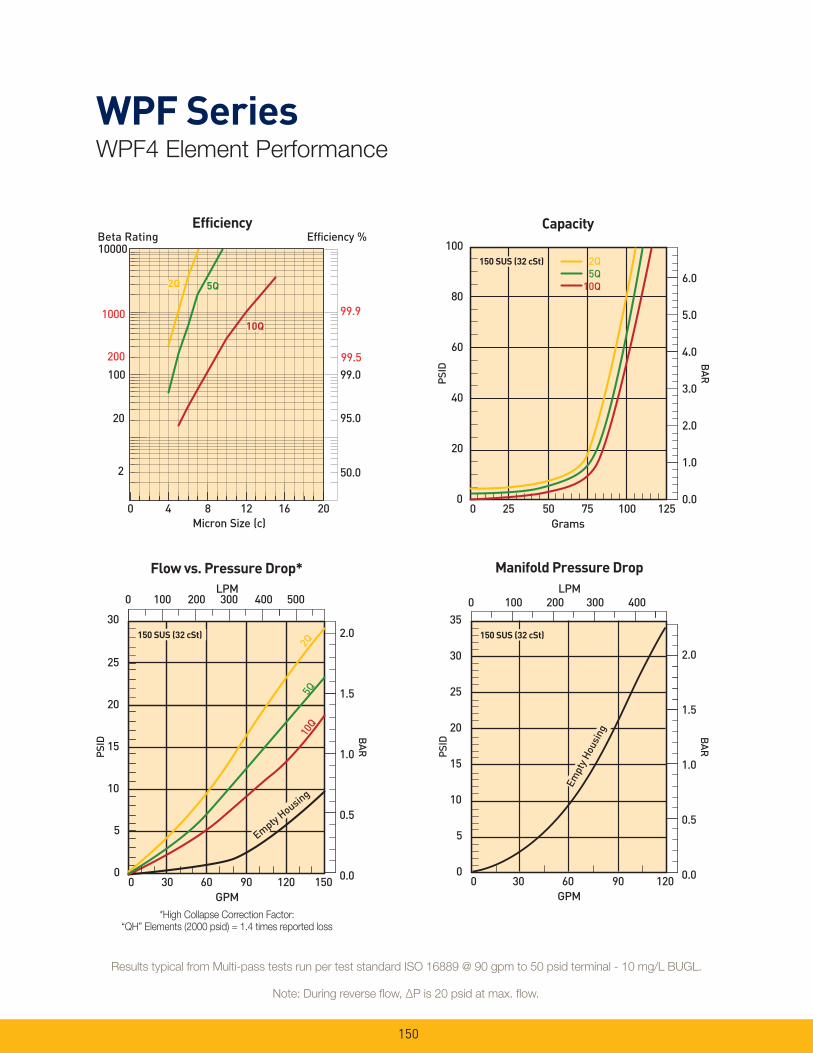
150
30
1.5
2.0
1.0
0.5
0.0
BAR
PSID
25
20
15
10
5
0
GPM
0 30 60 90 120 150
0 100 200 300 400 500
2Q5Q
10Q
Empty Housing
150 SUS (32 cSt)
LPM
Flow vs. Pressure Drop*
*High Collapse Correction Factor:
“QH” Elements (2000 psid) = 1.4 times reported loss
Note: During reverse fl ow, ΔP is 20 psid at max. fl ow.
Results typical from Multi-pass tests run per test standard ISO 16889 @ 90 gpm to 50 psid terminal - 10 mg/L BUGL.
WPF SeriesWPF4 Element Performance
100
4.0
6.0
2.0
5.0
3.0
1.0
0.0
BAR
PSID
80
60
40
20
0
Grams
0 25 50 75 100 125
Capacity
2Q5Q
10Q
150 SUS (32 cSt)
35
30
1.5
2.0
1.0
0.5
0.0
BAR
PSID
25
20
15
10
5
0
GPM
LPM
0 30 60 90 120
Empt
y Hou
sing
150 SUS (32 cSt)
Manifold Pressure Drop
0 100 200 300 400
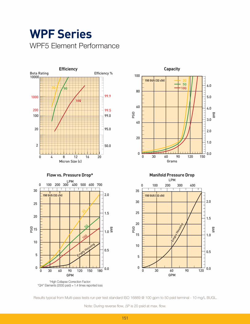
151
*High Collapse Correction Factor:
“QH” Elements (2000 psid) = 1.4 times reported loss
Note: During reverse fl ow, ΔP is 20 psid at max. fl ow.
Results typical from Multi-pass tests run per test standard ISO 16889 @ 100 gpm to 50 psid terminal - 10 mg/L BUGL.
WPF SeriesWPF5 Element Performance
30
1.5
2.0
1.0
0.5
0.0
BAR
PSID
25
20
15
10
5
0
GPM
0 30 60 90 120 150 180
0 100 200 300 400 500 600 700
2Q
5Q
10Q
Empty Housing
150 SUS (32 cSt)
LPM
Flow vs. Pressure Drop*
100
4.0
6.0
2.0
5.0
3.0
1.0
0.0
BAR
PSID
80
60
40
20
0
Grams
0 30 60 90 120 150
Capacity
150 SUS (32 cSt) 2Q5Q
10Q
35
30
1.5
2.0
1.0
0.5
0.0
BAR
PSID
25
20
15
10
5
0
GPM
LPM
0 30 60 90 120
Empt
y Hou
sing
150 SUS (32 cSt)
Manifold Pressure Drop
0 100 200 300 400
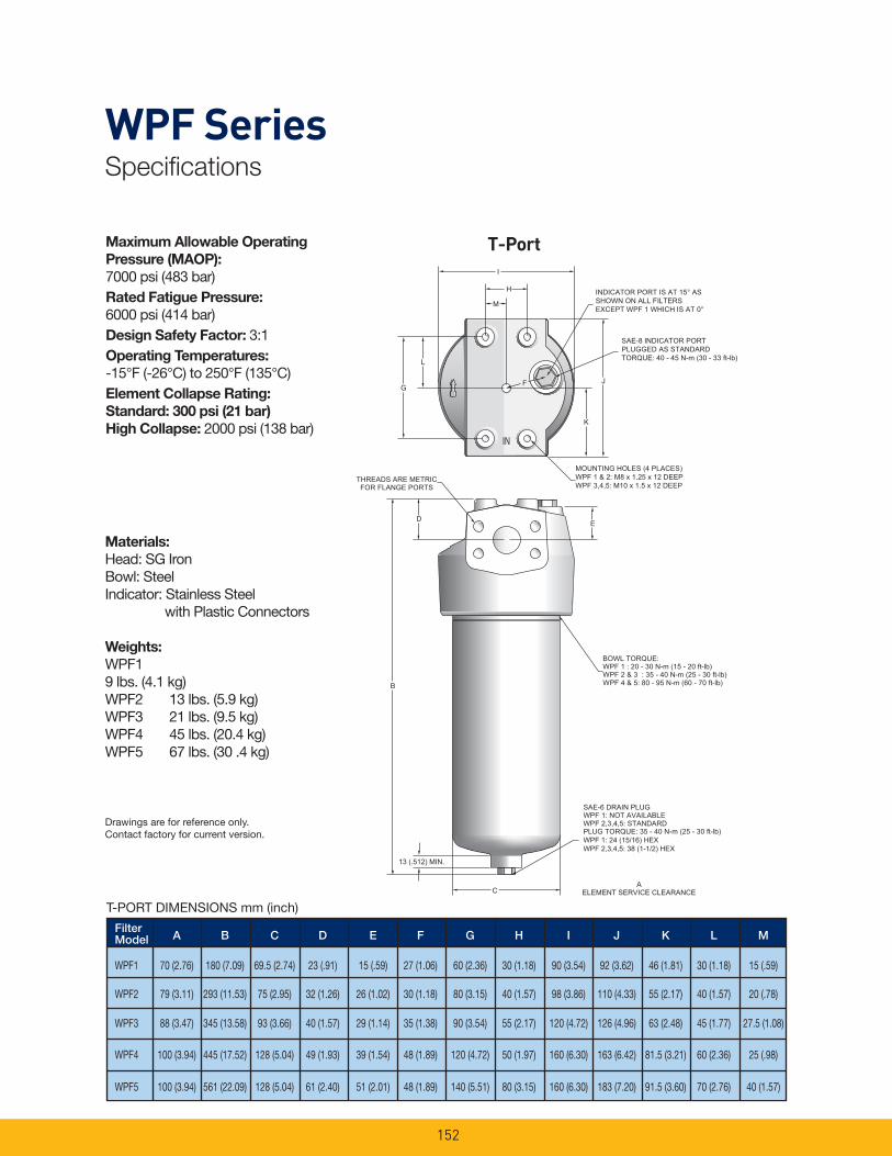
152
WPF SeriesSpecifi cations
Maximum Allowable Operating
Pressure (MAOP): 7000 psi (483 bar)Rated Fatigue Pressure:
6000 psi (414 bar)Design Safety Factor: 3:1Operating Temperatures:
-15°F (-26°C) to 250°F (135°C)Element Collapse Rating:
Standard: 300 psi (21 bar)
High Collapse: 2000 psi (138 bar)
Filter A B C D E F G H I J K L MModel
WPF1 70 (2.76) 180 (7.09) 69.5 (2.74) 23 (.91) 15 (.59) 27 (1.06) 60 (2.36) 30 (1.18) 90 (3.54) 92 (3.62) 46 (1.81) 30 (1.18) 15 (.59)
WPF2 79 (3.11) 293 (11.53) 75 (2.95) 32 (1.26) 26 (1.02) 30 (1.18) 80 (3.15) 40 (1.57) 98 (3.86) 110 (4.33) 55 (2.17) 40 (1.57) 20 (.78)
WPF3 88 (3.47) 345 (13.58) 93 (3.66) 40 (1.57) 29 (1.14) 35 (1.38) 90 (3.54) 55 (2.17) 120 (4.72) 126 (4.96) 63 (2.48) 45 (1.77) 27.5 (1.08)
WPF4 100 (3.94) 445 (17.52) 128 (5.04) 49 (1.93) 39 (1.54) 48 (1.89) 120 (4.72) 50 (1.97) 160 (6.30) 163 (6.42) 81.5 (3.21) 60 (2.36) 25 (.98)
WPF5 100 (3.94) 561 (22.09) 128 (5.04) 61 (2.40) 51 (2.01) 48 (1.89) 140 (5.51) 80 (3.15) 160 (6.30) 183 (7.20) 91.5 (3.60) 70 (2.76) 40 (1.57)
T-PORT DIMENSIONS mm (inch)
INDICATOR PORT IS AT 15° AS SHOWN ON ALL FILTERSEXCEPT WPF 1 WHICH IS AT 0°
SAE-8 INDICATOR PORTPLUGGED AS STANDARDTORQUE: 40 - 45 N-m (30 - 33 ft-lb)
MOUNTING HOLES (4 PLACES)WPF 1 & 2: M8 x 1.25 x 12 DEEPWPF 3,4,5: M10 x 1.5 x 12 DEEP
BOWL TORQUE:WPF 1 : 20 - 30 N-m (15 - 20 ft-lb)WPF 2 & 3 : 35 - 40 N-m (25 - 30 ft-lb)WPF 4 & 5: 80 - 95 N-m (60 - 70 ft-lb)
SAE-6 DRAIN PLUGWPF 1: NOT AVAILABLEWPF 2,3,4,5: STANDARDPLUG TORQUE: 35 - 40 N-m (25 - 30 ft-lb)WPF 1: 24 (15/16) HEXWPF 2,3,4,5: 38 (1-1/2) HEX
AELEMENT SERVICE CLEARANCE
THREADS ARE METRICFOR FLANGE PORTS
13 (.512) MIN.
Materials:
Head: SG IronBowl: SteelIndicator: Stainless Steel with Plastic Connectors
Weights:
WPF1 9 lbs. (4.1 kg)WPF2 13 lbs. (5.9 kg)WPF3 21 lbs. (9.5 kg)WPF4 45 lbs. (20.4 kg)WPF5 67 lbs. (30 .4 kg)
T-Port
Drawings are for reference only. Contact factory for current version.

153
WPF SeriesSpecifi cations
SAE-4 VENT PLUGTORQUE: 25 - 28 N-m (18 - 20 ft-lb)
M
P
BOWL TORQUE:WPF 2: 35 - 40 N-m (25 - 30 ft-lb)WPF 4 & 5: 80 - 95 N-m (60 - 70 ft-lb)
INLETWPF 4 & 5:
41.2 (1.622) C'BOREx 1.96 (.077) DEEP
34 (1.34) THRU2-127 SIZE O-RING INCLUDED
WPF 2:28.6 (1.125) C'BORE
x 1.96 (.077) DEEP22 (.866) THRU
2-119 SIZE O-RING INCLUDED
OUTLETWPF 4 & 5:
41.2 (1.622) C'BOREx 1.96 (.077) DEEP
34 (1.34) THRU2-127 SIZE O-RING INCLUDED
WPF 2:
28.6 (1.125) C'BOREx 1.96 (.077) DEEP
22 (.866) THRU 2-119 SIZE O-RING INCLUDED
ø
ø
ø
ø
ø
ø
ø
ø
SAE-6 DRAIN PLUGPLUG TORQUE: 35 - 40 N-m (25 - 30 ft-lb)HEX: 38 (1-1/2)
D
EF
AELEMENT SERVICE CLEARANCE
SAE-8 INDICATOR PORTPLUGGED AS STANDARDTORQUE: 40 - 45 N-m (30 - 33 ft-lb)
B
H
I
O
N
C
J
L
K
G
13 (.512) MIN.
Filter A B C D E F G H I J K L M N O PModel
WPF2 79 (3.11) 343(13.50) 75 (2.95) 24 (.94) 39 (1.53) 95 (3.74) 116 (4.57) 50 (1.97) 6 (.24) 110 (4.33) 80 (3.15) 40 (1.57) 110 (4.33) 121 (4.76) 17 (.67) 30 (1.18)
WPF4 100 (3.94) 532 (20.94) 128 (5.04) 38 (1.50) 57 (2.24) 140 (5.51) 150 (5.91) 75 (2.95) 13 (.51) 142 (5.59) 100 (3.94) 50 (1.97) 166.5 (6.56) 161 (6.34) 21 (.83) 31.7 (1.25)
WPF5 100 (3.94) 627 (24.69) 128 (5.04) 38 (1.50) 57 (2.24) 140 (5.51) 150 (5.91) 75 (2.95) 13 (.51) 142 (5.59) 100 (3.94) 50 (1.97) 166.5 (6.56) 161 (6.34) 21 (.83) 31.7 (1.25)
MANIFOLD DIMENSIONS mm (inch)
ManifoldMaximum Allowable Operating
Pressure (MAOP):
7000 psi (483 bar)Rated Fatigue Pressure: 6000 psi (414 bar)Design Safety Factor: 3:1Operating Temperatures:
-15°F (-26°C) to 250°F (135°C)Element Collapse Rating:
Standard: 300 psi (21 bar)High Collapse: 2000 psi (138 bar)
Materials:
Head: SG IronBowl: SteelIndicator: Stainless Steel with Plastic Connectors
Weights:
WPF2 18 lbs. (8.2 kg)WPF4 63 lbs. (28.6 kg)WPF5 70 lbs. (31.7 kg)
Drawings are for reference only. Contact factory for current version.
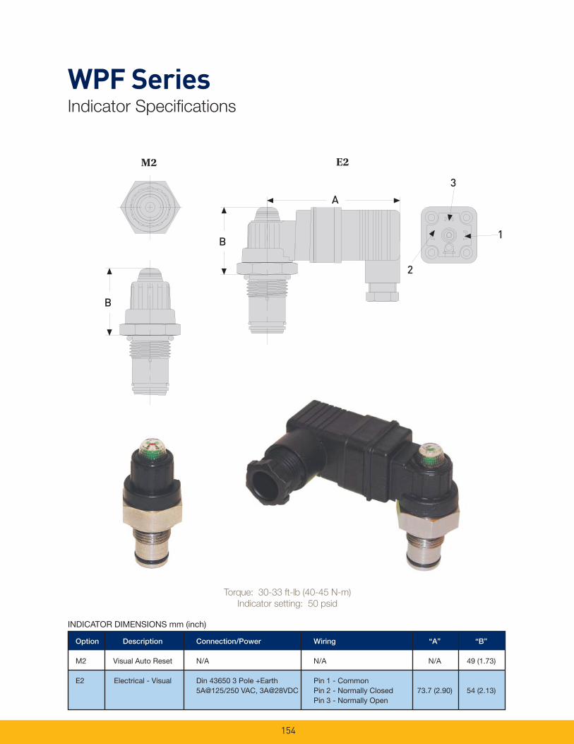
154
WPF SeriesIndicator Specifi cations
Option Description Connection/Power Wiring “A” “B”
M2 Visual Auto Reset N/A N/A N/A 49 (1.73)
E2 Electrical - Visual Din 43650 3 Pole +Earth Pin 1 - Common 5A@125/250 VAC, 3A@28VDC Pin 2 - Normally Closed 73.7 (2.90) 54 (2.13) Pin 3 - Normally Open
INDICATOR DIMENSIONS mm (inch)
B
E2A
2
1
3
B
M2 E2
Torque: 30-33 ft-lb (40-45 N-m)
Indicator setting: 50 psid
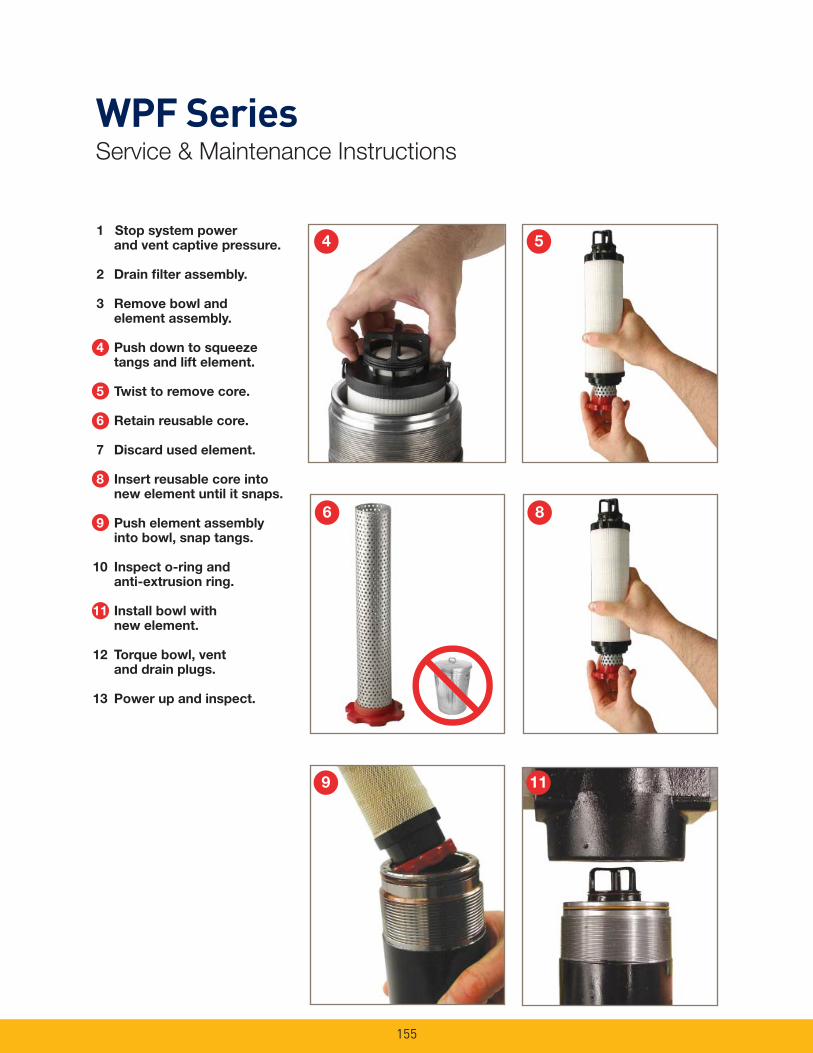
155
1 Stop system power and vent captive pressure.
2 Drain fi lter assembly.
3 Remove bowl and element assembly.
4 Push down to squeeze tangs and lift element.
5 Twist to remove core.
6 Retain reusable core.
7 Discard used element.
8 Insert reusable core into new element until it snaps.
9 Push element assembly into bowl, snap tangs.
10 Inspect o-ring and anti-extrusion ring.
11 Install bowl with new element.
12 Torque bowl, vent and drain plugs.
13 Power up and inspect.
WPF SeriesService & Maintenance Instructions
4 5
6 8
9 11
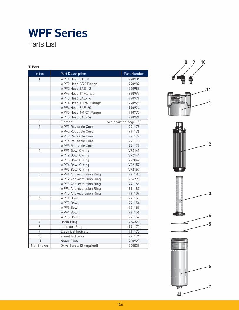
156
WPF SeriesParts List
T-Port8 9 10
11
1
2
3
4
5
6
7
Index Part Description Part Number
1 WPF1 Head SAE-8 940986
WPF2 Head 3/4” Flange 940989
WPF2 Head SAE-12 940988
WPF3 Head 1” Flange 940992
WPF3 Head SAE-16 940991
WPF4 Head 1-1/4” Flange 940923
WPF4 Head SAE-20 940924
WPF5 Head 1-1/2” Flange 940773
WPF5 Head SAE-24 940921
2 Element See chart on page 158
3 WPF1 Reusable Core 941175
WPF2 Reusable Core 941176
WPF3 Reusable Core 941177
WPF4 Reusable Core 941178
WPF5 Reusable Core 941179
4 WPF1 Bowl O-ring V92141
WPF2 Bowl O-ring V92144
WPF3 Bowl O-ring V92042
WPF4 Bowl O-ring V92157
WPF5 Bowl O-ring V92157
5 WPF1 Anti-extrusion Ring 941185
WPF2 Anti-extrusion Ring 934798
WPF3 Anti-extrusion Ring 941186
WPF4 Anti-extrusion Ring 941187
WPF5 Anti-extrusion Ring 941187
6 WPF1 Bowl 941153
WPF2 Bowl 941154
WPF3 Bowl 941155
WPF4 Bowl 941156
WPF5 Bowl 941157
7 Drain Plug 934320
8 Indicator Plug 941172
9 Electrical Indicator 941173
10 Visual Indicator 941174
11 Name Plate 920928
Not Shown Drive Screw (2 required) 900028

157
WPF SeriesParts List
Manifold1 12112
3
4
5
6
7
8
109
Index Part Description Part Number
1 WPF2 Manifold Mount Head 941273
WPF4 Manifold Mount Head 940982
WPF5 Manifold Mount Head 940982
2 WPF2 Manifold Mount O-rings (2 req’d) V92119
WPF4 Manifold Mount O-rings (2 req’d) V92127
WPF5 Manifold Mount O-rings (2 req’d) V92127
3 Element See chart on page 158
4 WPF2 Reusable Core 941176
WPF4 Reusable Core 941178
WPF5 Reusable Core 941179
5 WPF2 Bowl O-ring V92144
WPF4 Bowl O-ring V92157
WPF5 Bowl O-ring V92157
6 WPF2 Anti-extrusion Ring 934798
WPF4 Anti-extrusion Ring 941187
WPF5 Anti-extrusion Ring 941187
7 WPF2 Bowl 941154
WPF4 Bowl 941156
WPF5 Bowl 941157
8 Drain Plug 934320
9 Vent Plug 928882
10 WPF Indicator Plug 941172
11 Electrical Indicator 941173
12 Visual Indicator 941174
Not Shown Name Plate 920928
Not Shown Drive Screw (2 required) 900028

158
Select the desired symbol (in the correct position) to construct a model code. Example:
BOX 1 BOX 2 BOX 3 BOX 4 BOX 5 BOX 6 BOX 7 BOX 8
WPF 2 10QE V M2 K S12 1
BOX 1: Filter Series
Symbol Description
WPF High Pressure Filter
BOX 5: Indicator
Symbol Description
P Plugged indicator port
M2 Visual Automatic Reset
E2 Electrical/ Visual
(DIN43650 style connection)
Note: When the “M2” or “E2” option is selected, the indicator port is plugged and the indicator is shipped as a loose part.
BOX 4: Seals
Symbol Description
B Nitrile (NBR)
E Ethylene Propylene
V Fluorocarbon (FKM)
BOX 8: Options
Symbol Description
1 With Bypass
(for use with standard element only)
2 No Bypass (for use with high collapse element only)
Please note the bolded options refl ect
standard options with a reduced lead-time.
Consult factory on all other lead-time options.
BOX 2: Model
Symbol Description
1 1/2” Nominal ports
2 3/4” Nominal ports
3 1” Nominal ports
4 11/4” Nominal ports
5 11/2” Nominal ports
BOX 3: Media Code
Symbol Description
02QE Ecoglass III (bypass only)
05QE Ecoglass III (bypass only)
10QE Ecoglass III (bypass only)
02QH Microglass III (no bypass only)
10QH Microglass III (no bypass only)
High Collapse
BOX 6: Bypass
Symbol Description
K 50 PSID (3.5 bar)
X No Bypass and No Indicator (port plugged)
Note: When an indicator and no bypass (“2” in Box 8) is selected, the indicator setting is 50 psid (3.5 bar).
BOX 7: Ports
Symbol Description
WPF1
S08 SAE-8 Ports
WPF2
S12 SAE-12 Ports
Y12 3/4” SAE Code 62 Flange face
X12 Manifold
WPF3
S16 SAE-16 Ports
Y16 1” SAE Code 62 Flange face
WPF4
S20 SAE-20 Ports
Y20 1 1/4” SAE Code 62 Flange face
X20 Manifold
WPF5
S24 SAE-24 Ports
Y24 1 1/2” SAE Code 62 Flange face
X24 Manifold
WPF SeriesHow to Order
Replacement Elements:
Media WPF1 WPF2 WPF3 WPF4 WPF5
Standard Collapse
(300 psid/21 bar)
Ecoglass III, 02QE 941029Q 941032Q 941035Q 941038Q 941041Q
Ecoglass III, 05QE 941030Q 941033Q 941036Q 941039Q 941042Q
Ecoglass III, 10QE 941031Q 941034Q 941037Q 941040Q 941043Q
High Collapse
(2000 psid/138 bar)
Microglass III, 02QH 941044Q 941046Q 941048Q 941050Q 941052Q
Microglass III, 10QH 941045Q 941047Q 941049Q 941051Q 941053Q
Global products as identifi ed are offered worldwide through all Parker locations and utilize a common ordering code.

159
12S SeriesHigh Pressure Filters
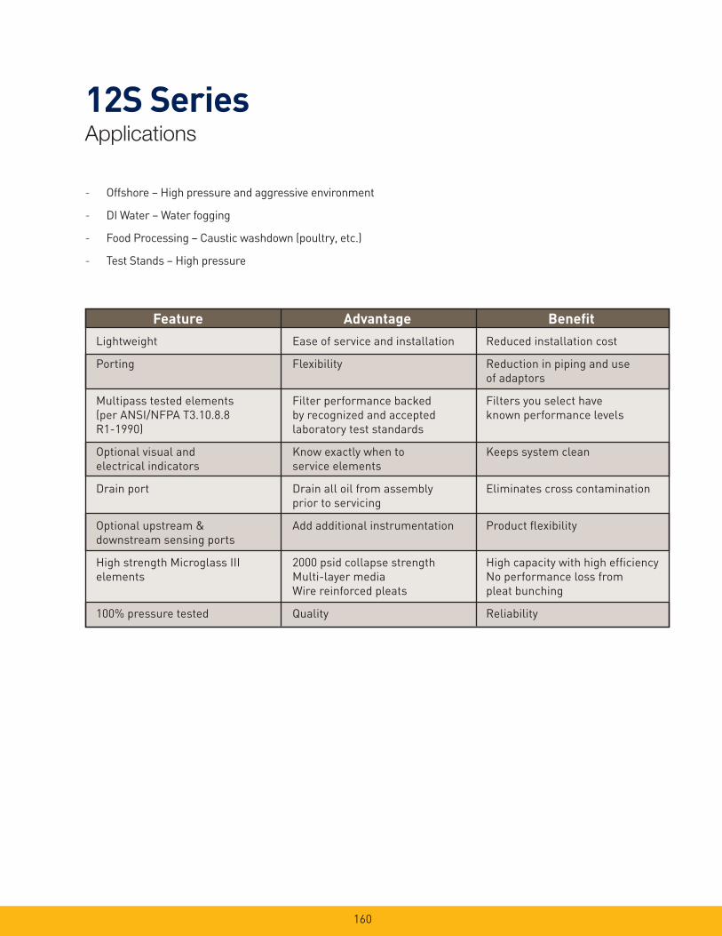
160
12S SeriesApplications
- Offshore – High pressure and aggressive environment
- DI Water – Water fogging
- Food Processing – Caustic washdown (poultry, etc.)
- Test Stands – High pressure
Feature Advantage Benefi t
Lightweight
Porting
Multipass tested elements
(per ANSI/NFPA T3.10.8.8
R1-1990)
Optional visual and
electrical indicators
Drain port
Optional upstream &
downstream sensing ports
High strength Microglass III
elements
100% pressure tested
Ease of service and installation
Flexibility
Filter performance backed
by recognized and accepted
laboratory test standards
Know exactly when to
service elements
Drain all oil from assembly
prior to servicing
Add additional instrumentation
2000 psid collapse strength
Multi-layer media
Wire reinforced pleats
Quality
Reduced installation cost
Reduction in piping and use
of adaptors
Filters you select have
known performance levels
Keeps system clean
Eliminates cross contamination
Product fl exibility
High capacity with high effi ciency
No performance loss from
pleat bunching
Reliability
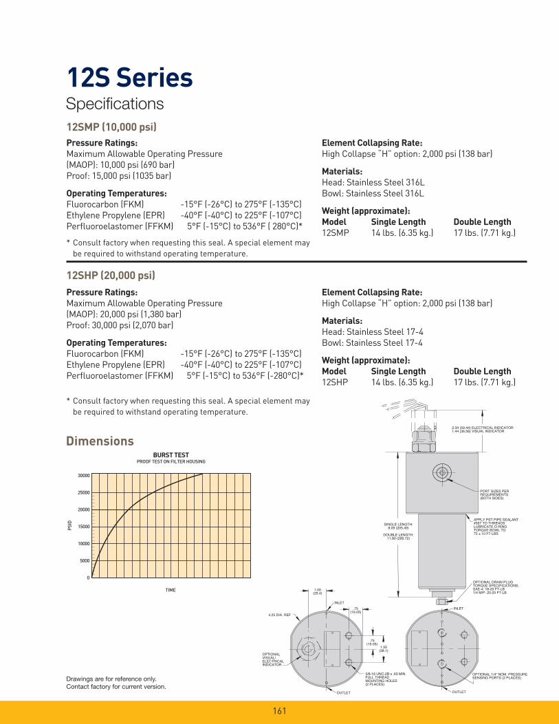
161
12S SeriesSpecifi cations
Pressure Ratings:
Maximum Allowable Operating Pressure
(MAOP): 10,000 psi (690 bar)
Proof: 15,000 psi (1035 bar)
Operating Temperatures:
Fluorocarbon (FKM) -15°F (-26°C) to 275°F (-135°C)
Ethylene Propylene (EPR) -40°F (-40°C) to 225°F (-107°C)
Perfl uoroelastomer (FFKM) 5°F (-15°C) to 536°F ( 280°C)*
30000
25000
20000
15000
10000
5000
0
PSID
BURST TEST
TIME
PROOF TEST ON FILTER HOUSING
Element Collapsing Rate:
High Collapse “H” option: 2,000 psi (138 bar)
Materials:
Head: Stainless Steel 316L
Bowl: Stainless Steel 316L
Weight (approximate):
Model Single Length Double Length
12SMP 14 lbs. (6.35 kg.) 17 lbs. (7.71 kg.)* Consult factory when requesting this seal. A special element may
be required to withstand operating temperature.
Pressure Ratings:
Maximum Allowable Operating Pressure
(MAOP): 20,000 psi (1,380 bar)
Proof: 30,000 psi (2,070 bar)
Operating Temperatures:
Fluorocarbon (FKM) -15°F (-26°C) to 275°F (-135°C)
Ethylene Propylene (EPR) -40°F (-40°C) to 225°F (-107°C)
Perfl uoroelastomer (FFKM) 5°F (-15°C) to 536°F (-280°C)*
Element Collapsing Rate:
High Collapse “H” option: 2,000 psi (138 bar)
Materials:
Head: Stainless Steel 17-4
Bowl: Stainless Steel 17-4
Weight (approximate):
Model Single Length Double Length
12SHP 14 lbs. (6.35 kg.) 17 lbs. (7.71 kg.)
Dimensions
IO
OPTIONAL 1/4" NOM. PRESSURESENSING PORTS (2 PLACES)
OUTLET
INLET
SINGLE LENGTH:8.09 (205.49)
DOUBLE LENGTH:11.80 (299.72)
APPLY PST PIPE SEALANT#567 TO THREADSLUBRICATE O-RINGTORQUE BOWL TO75 ± 10 FT-LBS
OPTIONAL DRAIN PLUGTORQUE SPECIFICATIONS:SAE-4: 18-20 FT-LB1/4 M/P: 20-25 FT-LB
PORT SIZES PERREQUIREMENTS(BOTH SIDES)
2.34 (59.44) ELECTRICAL INDICATOR1.44 (36.58) VISUAL INDICATOR
OI
OPTIONALVISUAL/ELECTRICALINDICATOR
3/8-16 UNC-2B x .63 MIN.FULL THREADMOUNTING HOLES(2 PLACES)
4.25 DIA. REF
1.00(25.4)
.75(19.05)
.75(19.05)
OUTLET
INLET
1.50(38.1)
* Consult factory when requesting this seal. A special element may
be required to withstand operating temperature.
Drawings are for reference only. Contact factory for current version.
12SHP (20,000 psi)
12SMP (10,000 psi)

162
12S Series12S-1 Element Performance
LPM
25
20
15
10
5
0
05QH
20QH
10QH
PSID
GPM
1.5
1.0
0.5
0.0
BAR
150SUS150SUS
02QH
0 5 10 15 20
0 10 20 30 40 50 60 70
Flow vs. Pressure Loss
CapacityBAR
Grams
100
80
60
40
20
0
6
5
4
3
2
1
0
PSID
0 1 2 3 4 5 6
02QH
20QH
10QH
05QH
LPM
25
20
15
10
5
0
PSID
GPM
1.5
1.0
0.5
0.0
BAR
3/4 M/P
SAE-8
SAE-10
SAE-12
1 NPTF
0 20 40 60 80
0 5 10 15 20 25
HOUSINGSHOUSINGSHOUSINGS
Efficiency %Efficiency
Beta Rating
1000
10000
99.9
99.599.0100
200
20
2 50.0
95.0
Micron Size (c)
2Q
10Q
20Q
2Q
10Q
20Q
2QH
10QH
20QH
5Q5QH
0 4 8 12 16 20
Multipass tests run @ 10 gpm to 100 psid terminal - 5mg/L BUGL

163
12S Series12S-2 Element Performance
LPM
25
20
15
10
5
0
02QH
20QH10QH
PSID
GPM
1.5
1.0
0.5
0.0
BAR
05QH
0 5 10 15 20 25
0 20 40 60 80
150SUS150SUS
CapacityBAR
Grams
100
80
60
40
20
0
6
5
4
3
2
1
0
PSID
10QH
02QH
05QH
20QH
0 5 10 15 20
Flow vs. Pressure Loss
LPM
25
20
15
10
5
0
PSI
D
GPM
1.5
1.0
0.5
0.0
BA
R
0 20 40 60 80
0 5 10 15 20 25
HOUSINGSHOUSINGS
3/4 M/P
SAE-8
SAE-10
SAE-12
1 NPTF
Efficiency %Efficiency
Beta Rating
1000
10000
99.9
99.599.0100
200
20
2 50.0
95.0
Micron Size (c)
2Q
10Q
20Q
2Q
10Q
20Q
2QH
10QH
20QH
5Q5QH
0 4 8 12 16 20
Multipass tests run @ 15 gpm to 100 psid terminal - 5mg/L BUGL
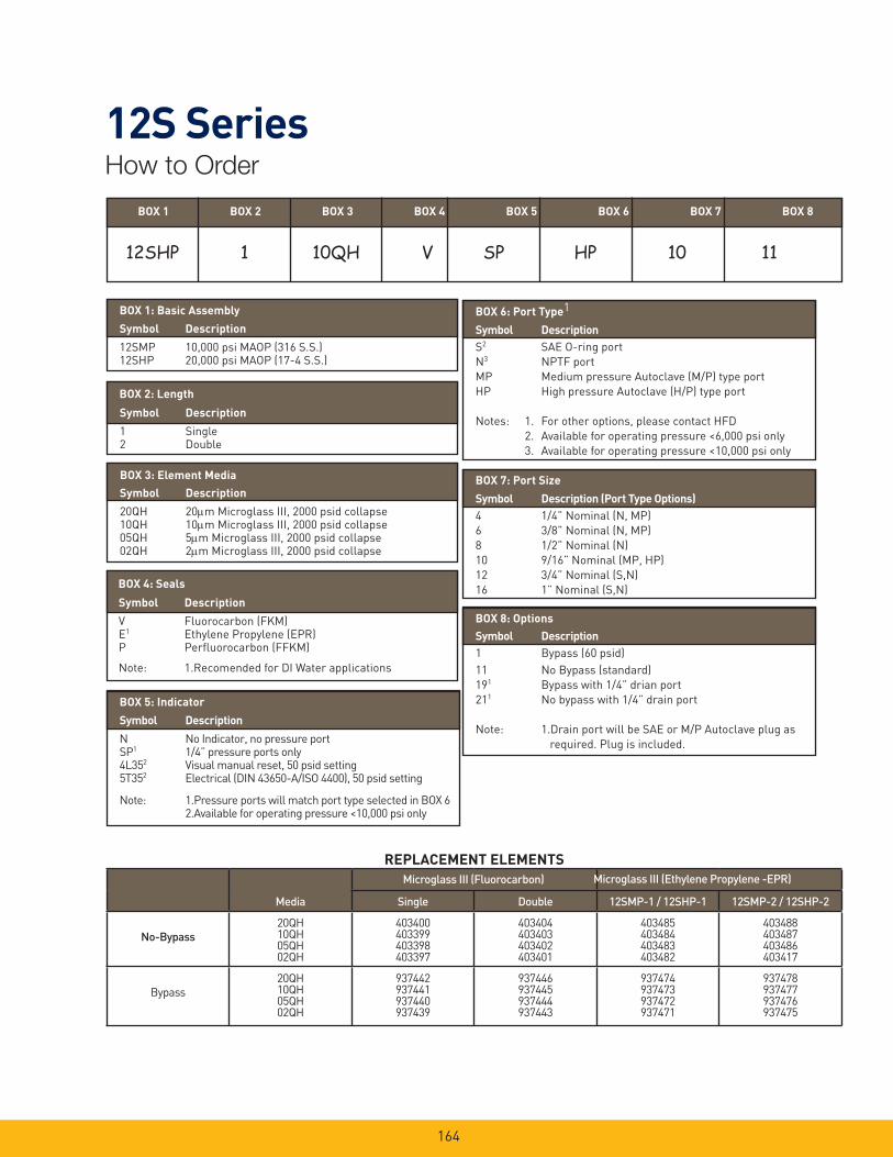
164
12S SeriesHow to Order
BOX 2: Length
Symbol Description
1 Single2 Double
BOX 3: Element Media
Symbol Description
20QH 20m Microglass III, 2000 psid collapse10QH 10m Microglass III, 2000 psid collapse05QH 5m Microglass III, 2000 psid collapse02QH 2m Microglass III, 2000 psid collapse
BOX 1: Basic Assembly
Symbol Description
12SMP 10,000 psi MAOP (316 S.S.)12SHP 20,000 psi MAOP (17-4 S.S.)
BOX 1 BOX 2 BOX 3 BOX 4 BOX 5 BOX 6 BOX 7 BOX 8
REPLACEMENT ELEMENTS
BOX 4: Seals
Symbol Description
V Fluorocarbon (FKM)E1 Ethylene Propylene (EPR)P Perfl uorocarbon (FFKM)
Note: 1.Recomended for DI Water applications
BOX 5: Indicator
Symbol Description
N No Indicator, no pressure portSP1 1/4” pressure ports only4L352 Visual manual reset, 50 psid setting5T352 Electrical (DIN 43650-A/ISO 4400), 50 psid setting
Note: 1.Pressure ports will match port type selected in BOX 6 2.Available for operating pressure <10,000 psi only
BOX 6: Port Type1
Symbol Description
S2 SAE O-ring port
N3 NPTF port
MP Medium pressure Autoclave (M/P) type port
HP High pressure Autoclave (H/P) type port
Notes: 1. For other options, please contact HFD
2. Available for operating pressure <6,000 psi only
3. Available for operating pressure <10,000 psi only
BOX 7: Port Size
Symbol Description (Port Type Options)
4 1/4” Nominal (N, MP)
6 3/8” Nominal (N, MP)
8 1/2” Nominal (N)
10 9/16” Nominal (MP, HP)
12 3/4” Nominal (S,N)
16 1” Nominal (S,N)
BOX 8: Options
Symbol Description
1 Bypass (60 psid)
11 No Bypass (standard)
191 Bypass with 1/4” drian port
211 No bypass with 1/4” drain port
Note: 1.Drain port will be SAE or M/P Autoclave plug as
required. Plug is included.
Media Single Double 12SMP-1 / 12SHP-1 12SMP-2 / 12SHP-2
No-Bypass20QH10QH05QH02QH
403400403399403398403397
403404403403403402403401
403485403484403483403482
403488403487403486403417
Bypass
20QH10QH05QH02QH
937442937441937440937439
937446937445937444937443
937474937473937472937471
937478937477937476937475
Microglass III (Ethylene Propylene -EPR)Microglass III (Fluorocarbon)
12SHP 1 10QH V SP HP 10 11
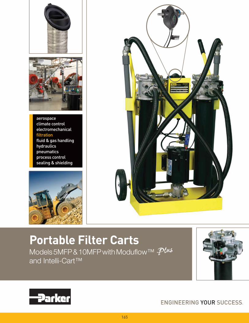
Portable Filter CartsModels 5MFP & 10MFP with Modufl ow™
and Intelli-Cart™
165

166
• Filtering new fl uid before
putting into service
• Transferring fl uid from
drums or storage tanks to
system reservoirs
• Conditioning fl uid that is
already in use
• Complimenting existing
system fi ltration
• Removing free and
emulsifi ed water from a
system
• For use with fl uids such as
hydraulic, gear and lube oils
Parker portable fi lter carts are the ideal way to prefi lter and transfer fl uids into reservoirs or to clean up existing systems.
Fluid should always be fi ltered before being put into use. New fl uid is not necessarily clean fl uid. Most new fl uids (right out of the drum) are unfi t for use due to high initial contamination levels. Contamination, both particulate and water, may be added to a new fl uid during processing, mixing, handling and storage.
Water is removed by installing Par-Gel™ elements in the outlet fi lter. Par-Gel™ elements are made from a polymer which has a very high affi nity for free water.
Once water comes into contact with this material, it is removed from the system.
The Parker portable fi lter cart uses two high capacity ModuFlow™ Plus fi lters for long element life and better system protection. The fi rst stage (inlet) fi lter captures larger particles, while the second stage (outlet) fi lter captures fi ner particles or removes water. A rugged industrial quality gear pump gets the job done fast.
Using a Parker portable fi lter cart is the most economical way to protect your system from the harm that can be caused by contamination.
Features
• Two fi lters instead of one w/ 2.5 times increased dirt holding capacity
• Wide variety of particulate elements available
• Par-Gel™ water removal elements available
• Heavy duty frame
• Lightweight and portable
• Two fl ow rates available: 5 gpm or 10 gpm
• Eleven-foot hose and wand assemblies included
Advantages
• Pump protection and long element life
• Capable of getting a fl uid to a desired cleanliness level
• Removes “free water” from a system
• Rugged and durable
• Easy to move from place-to-place
• Enables use in low or high viscosity applications
• Additional hardware not necessary
Benefi ts
• Element cost savings and trouble-free service
• Extends fl uid life and system performance
• Gets dirt and water out of system with one process
• Built to last
• One person operation
• Matched to your needs
• Ready to use as received
Portable Filter CartsApplications
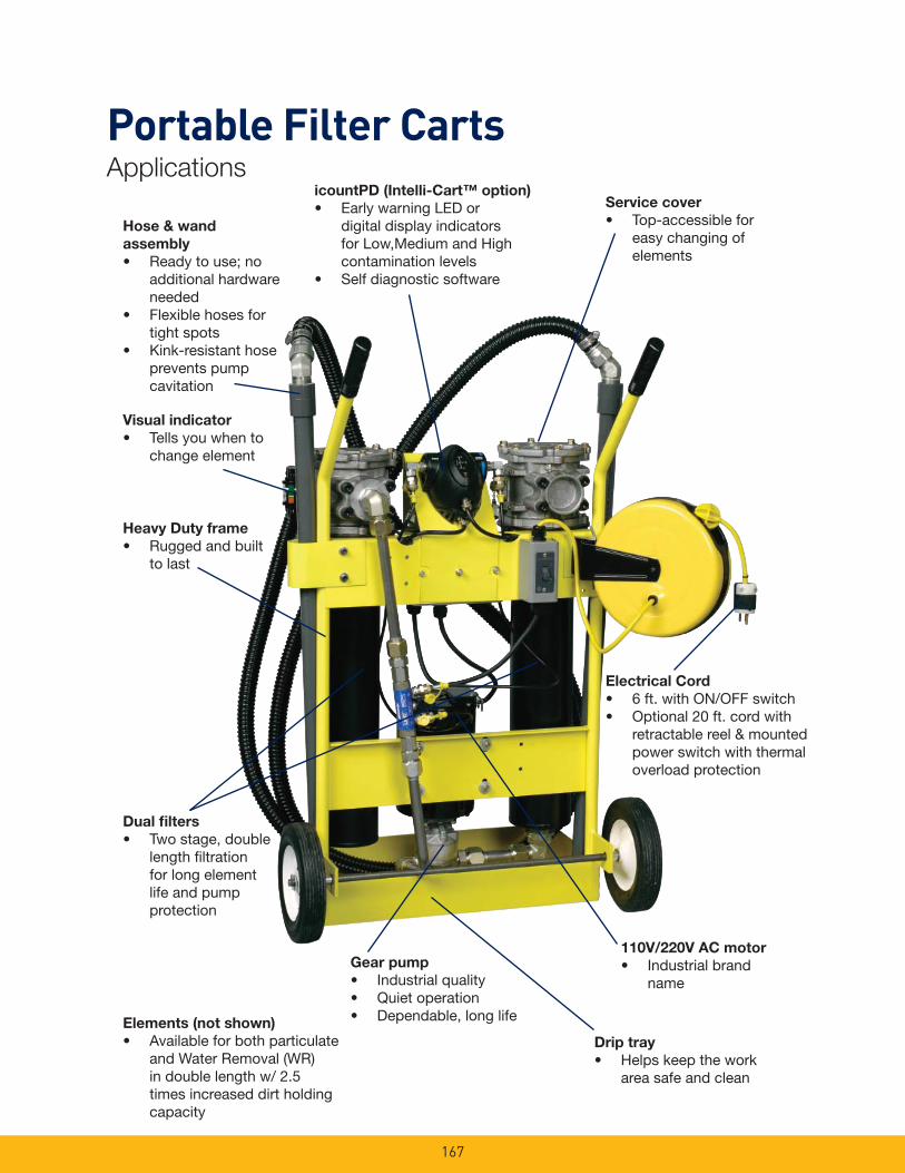
167
Elements (not shown)
• Available for both particulate and Water Removal (WR) in double length w/ 2.5 times increased dirt holding capacity
Electrical Cord
• 6 ft. with ON/OFF switch• Optional 20 ft. cord with
retractable reel & mounted power switch with thermal overload protection
Service cover
• Top-accessible for easy changing of elements
Dual fi lters
• Two stage, double length fi ltration for long element life and pump protection
Hose & wand
assembly
• Ready to use; no additional hardware needed
• Flexible hoses for tight spots
• Kink-resistant hose prevents pump cavitation
Gear pump
• Industrial quality• Quiet operation• Dependable, long life
Drip tray
• Helps keep the work area safe and clean
Visual indicator
• Tells you when to change element
110V/220V AC motor
• Industrial brand name
Heavy Duty frame
• Rugged and built to last
icountPD (Intelli-Cart™ option)
• Early warning LED or digital display indicators for Low,Medium and High contamination levels
• Self diagnostic software
Portable Filter CartsApplications
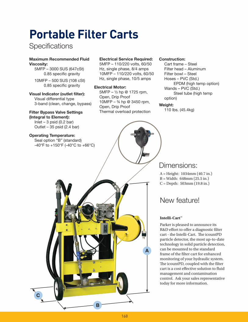
168
Maximum Recommended Fluid
Viscosity:
5MFP – 3000 SUS (647cSt) 0.85 specifi c gravity
10MFP – 500 SUS (108 cSt) 0.85 specifi c gravity
Visual Indicator (outlet fi lter):
Visual differential type 3-band (clean, change, bypass)
Filter Bypass Valve Settings
(Integral to Element):
Inlet – 3 psid (0.2 bar) Outlet – 35 psid (2.4 bar)
Operating Temperature:
Seal option “B” (standard) -40°F to +150°F (-40°C to +66°C)
Electrical Service Required:
5MFP – 110/220 volts, 60/50 Hz, single phase, 8/4 amps
10MFP – 110/220 volts, 60/50 Hz, single phase, 10/5 amps
Electrical Motor:
5MFP – ½ hp @ 1725 rpm, Open, Drip Proof
10MFP – ¾ hp @ 3450 rpm, Open, Drip Proof
Thermal overload protection
Construction:
Cart frame – Steel Filter head – Aluminum Filter bowl – Steel Hoses – PVC (Std.) EPDM (high temp option) Wands – PVC (Std.) Steel tube (high temp
option)
Weight:
110 lbs. (45.4kg)
A
Dimensions:A = Height: 1034mm (40.7 in.)B = Width: 648mm (25.5 in.)C = Depth: 503mm (19.8 in.)
B
New feature!
C
Intelli-Cart™
Parker is pleased to announce its R&D eff ort to off er a diagnostic fi lter cart - the Intelli-Cart. Th e icountPD particle detector, the most up-to-date technology in solid particle detection, can be mounted to the standard frame of the fi lter cart for enhanced monitoring of your hydraulic system. Th e icountPD, coupled with the fi lter cart is a cost eff ective solution to fl uid management and contamination control. Ask your sales representative today for more information.
Portable Filter CartsSpecifi cations
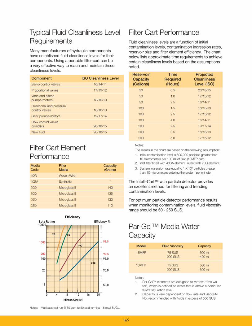
169
Notes:
1. Par-Gel™ elements are designed to remove “free wa-
ter”, which is defi ned as water that is above a particular
fl uid’s saturation level.
2. Capacity is very dependent on fl ow rate and viscosity.
Not recommended with fl uids in excess of 500 SUS.
Typical Fluid Cleanliness Level
Requirements
Many manufacturers of hydraulic components have established fl uid cleanliness levels for their components. Using a portable fi lter cart can be a very effective way to reach and maintain these cleanliness levels.
Filter Cart Performance
Fluid cleanliness levels are a function of initial contamination levels, contamination ingression rates, reservoir size and fi lter element effi ciency. The chart below lists approximate time requirements to achieve certain cleanliness levels based on the assumptions noted.
Notes:
The results in the chart are based on the following assumption:
1. Initial contamination level is 500,000 particles greater than
10 micrometers per 100 ml of fl uid (10MFP cart).
2. Inlet fi lter fi tted with 40SA element; outlet with 20Q element.
3. System ingression rate equal to 1 X 10⁶ particles greater
than 10 micrometers entering the system per minute.
Reservoir Time Projected Capacity Required Cleanliness (Gallons) (Hours) Level (ISO) 50 0.5 20/18/15
50 1.0 17/15/12
50 2.5 16/14/11
100 1.5 18/16/13
100 2.5 17/15/12
100 4.0 16/14/11
200 2.5 19/17/14
200 3.5 18/16/13
200 5.0 17/15/12
Component ISO Cleanliness Level
Servo control valves 16/14/11
Proportional valves 17/15/12
Vane and piston
pumps/motors 18/16/13
Directional and pressure
control valves 18/16/13
Gear pumps/motors 19/17/14
Flow control valves
cylinders 20/18/15
New fl uid 20/18/15
Filter Cart Element
PerformanceMedia Filter CapacityCode Media (Grams)
40W Woven Wire *
40SA Synthetic *
20Q Microglass III 140
10Q Microglass III 135
05Q Microglass III 130
02Q Microglass III 110
Notes: Multipass test run @ 80 gpm to 50 psid terminal - 5 mg/l BUGL.
Model Fluid Viscosity Capacity
5MFP 75 SUS 600 ml
200 SUS 420 ml
10MFP 75 SUS 500 ml
200 SUS 300 ml
Par-Gel™ Media Water
Capacity
Efficiency %Efficiency
Beta Rating
1000
10000
99.9
99.599.0100
200
20
2 50.0
95.0
Micron Size (c)
2Q
10Q
20Q
2Q
10Q
20Q
2Q
10Q
20Q
5Q5Q
0 4 8 12 16 20
The Intelli-Cart™ with particle detector provides an excellent method for fi ltering and trending contamination levels.
For optimum particle detector performance results when monitoring contamination levels, fl uid viscosity range should be 50 - 250 SUS.
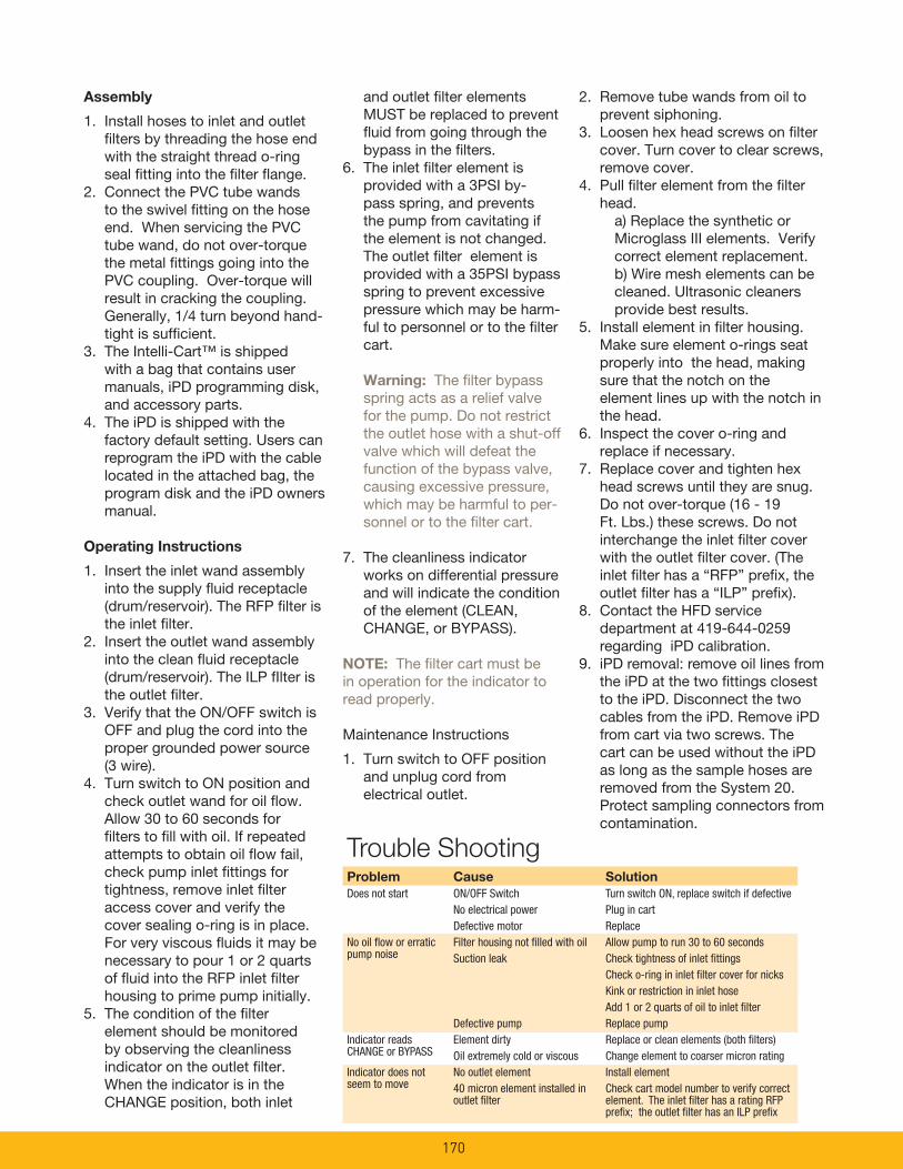
170
2. Remove tube wands from oil to prevent siphoning.
3. Loosen hex head screws on fi lter cover. Turn cover to clear screws, remove cover.
4. Pull fi lter element from the fi lter head.
a) Replace the synthetic or Microglass III elements. Verify correct element replacement.
b) Wire mesh elements can be cleaned. Ultrasonic cleaners provide best results.
5. Install element in fi lter housing. Make sure element o-rings seat properly into the head, making sure that the notch on the element lines up with the notch in the head.
6. Inspect the cover o-ring and replace if necessary.
7. Replace cover and tighten hex head screws until they are snug. Do not over-torque (16 - 19 Ft. Lbs.) these screws. Do not interchange the inlet fi lter cover with the outlet fi lter cover. (The inlet fi lter has a “RFP” prefi x, the outlet fi lter has a “ILP” prefi x).
8. Contact the HFD service department at 419-644-0259 regarding iPD calibration.
9. iPD removal: remove oil lines from the iPD at the two fi ttings closest to the iPD. Disconnect the two cables from the iPD. Remove iPD from cart via two screws. The cart can be used without the iPD as long as the sample hoses are removed from the System 20. Protect sampling connectors from contamination.
Assembly
1. Install hoses to inlet and outlet fi lters by threading the hose end with the straight thread o-ring seal fi tting into the fi lter fl ange.
2. Connect the PVC tube wands to the swivel fi tting on the hose end. When servicing the PVC tube wand, do not over-torque the metal fi ttings going into the PVC coupling. Over-torque will result in cracking the coupling. Generally, 1/4 turn beyond hand-tight is suffi cient.
3. The Intelli-Cart™ is shipped with a bag that contains user manuals, iPD programming disk, and accessory parts.
4. The iPD is shipped with the factory default setting. Users can reprogram the iPD with the cable located in the attached bag, the program disk and the iPD owners manual.
Operating Instructions
1. Insert the inlet wand assembly into the supply fl uid receptacle(drum/reservoir). The RFP fi lter is the inlet fi lter.
2. Insert the outlet wand assembly into the clean fl uid receptacle (drum/reservoir). The ILP fIlter is the outlet fi lter.
3. Verify that the ON/OFF switch is OFF and plug the cord into the proper grounded power source (3 wire).
4. Turn switch to ON position and check outlet wand for oil fl ow. Allow 30 to 60 seconds for fi lters to fi ll with oil. If repeated attempts to obtain oil fl ow fail, check pump inlet fi ttings for tightness, remove inlet fi lter access cover and verify the cover sealing o-ring is in place. For very viscous fl uids it may be necessary to pour 1 or 2 quarts of fl uid into the RFP inlet fi lter housing to prime pump initially.
5. The condition of the fi lter element should be monitored by observing the cleanliness indicator on the outlet fi lter. When the indicator is in the CHANGE position, both inlet
and outlet fi lter elements MUST be replaced to prevent fl uid from going through the bypass in the fi lters.
6. The inlet fi lter element is provided with a 3PSI by-pass spring, and prevents the pump from cavitating if the element is not changed. The outlet fi lter element is provided with a 35PSI bypass spring to prevent excessive pressure which may be harm-ful to personnel or to the fi lter cart.
Warning: The fi lter bypass spring acts as a relief valve for the pump. Do not restrict the outlet hose with a shut-off valve which will defeat the function of the bypass valve, causing excessive pressure, which may be harmful to per-sonnel or to the fi lter cart.
7. The cleanliness indicator works on differential pressure and will indicate the condition of the element (CLEAN, CHANGE, or BYPASS).
NOTE: The fi lter cart must be in operation for the indicator to read properly.
Maintenance Instructions
1. Turn switch to OFF position and unplug cord from electrical outlet.
Trouble ShootingProblem Cause Solution
Does not start ON/OFF Switch Turn switch ON, replace switch if defective No electrical power Plug in cart Defective motor ReplaceNo oil fl ow or erratic Filter housing not fi lled with oil Allow pump to run 30 to 60 secondspump noise Suction leak Check tightness of inlet fi ttings Check o-ring in inlet fi lter cover for nicks Kink or restriction in inlet hose Add 1 or 2 quarts of oil to inlet fi lter Defective pump Replace pumpIndicator reads Element dirty Replace or clean elements (both fi lters)CHANGE or BYPASS Oil extremely cold or viscous Change element to coarser micron ratingIndicator does not No outlet element Install elementseem to move 40 micron element installed in Check cart model number to verify correct outlet fi lter element. The inlet fi lter has a rating RFP prefi x; the outlet fi lter has an ILP prefi x
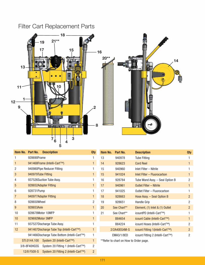
171
Item No. Part No. Description Qty
1 928690 Frame 1
1 941468 Frame (Intelli-Cart™) 1
2 940980 Pipe Reducer Fitting 1
3 940979 Tube Fitting 1
4 937526 Suction Tube Assy. 1
5 928652 Adapter Fitting 1
6 928731 Pump 1
7 940977 Adapter Fitting 1
8 928650 Wheel 2
9 928653 Axle 1
10 928678 Motor 10MFP 1
10 929692 Motor 5MFP 1
11 937527 Discharge Tube Assy. 1
12 941467 Discharge Tube Top (Intelli-Cart™) 1
941466 Discharge Tube Bottom (Intelli-Cart™) 1
STI.0144.100 System 20 (Intelli-Cart™) 1
3/8-8F40HG5S System 20 Fitting 1 (Intelli-Cart™) 2
12/8 F50X-S System 20 Fitting 2 (Intelli-Cart™) 2
Item No. Part No. Description Qty
13 940978 Tube Fitting 1
14 928623 Cord Reel 1
15 940960 Inlet Filter – Nitrile 1
15 941024 Inlet Filter – Fluorocarbon 1
16 928784 Tube Wand Assy. – Seal Option B 2
17 940961 Outlet Filter – Nitrile 1
17 941025 Outlet Filter – Fluorocarbon 1
18 928663 Hose Assy. – Seal Option B 2
19 928651 Handle Grip 2
20 See Chart** Element, (1) Inlet & (1) Outlet 2
21 See Chart** icountPD (Intelli-Cart™) 1
B84654 icount Cable (Intelli-Cart™) 1
B84224 icount Hoses (Intelli-Cart™) 2
2/2A40EG4M-S icount Fitting 1(Intelli-Cart™) 2
EMA3/1/8ED icount Fitting 2 (Intelli-Cart™) 2
**Refer to chart on How to Order page.
5
1517
14
8
1
10
2
11
13
6
18
16
9
20**
34
7
19
Filter Cart Replacement Parts
21**
12

172
BOX 2: Length
Symbol Description
2 Double
BOX 6: Indicator
Symbol Description
VP Visual indicator, 3-band
(mounted on Outlet Filter only)
BOX 7: Bypass
Symbol Description
I 35 PSID (2.4 bar)
(outlet fi lter element)
BOX 1 BOX 2 BOX 3 BOX 4 BOX 5 BOX 6 BOX 7 BOX 8
10MFP 2 40SA 10Q B VP I 1
BOX 1: Basic Assembly
Symbol Description
5MFP 5 GPM (3000 SUS MAX.)
10MFP 10 GPM (500 SUS MAX.)
BOX 3: Inlet Filter Element
Symbol Description
40SA Synthetic, 40 micron
40W Stainless Steel Mesh, 40 micron nominal
20Q Microglass III, 20 micron
BOX 4: Outlet Filter Element
Symbol Description
02Q Microglass III, 2 micron
05Q Microglass III, 5 micron
10Q Microglass III, 10 micron
20Q Microglass III, 20 micron
WR Par-Gel™ Water Removal
BOX 5: Seals
Symbol Description
B Nitrile (NBR)
BOX 8: Options
Symbol Description
1 None
6* 20’ electrical cord (retractable reel)
9 Visual indicator on Inlet FilterPD** iPD with standard LED DisplayPDL** iPD with LCD display and integrated Moisture Sensor
Media
02Q
05Q
10Q
20Q
40SA
40W
WR
Inlet Filter
(3 psid integral bypass)
N/A
N/A
N/A
940971Q
940802
940803
N/A
Outlet Filter
(35 psid integral bypass)
937397Q
937398Q
937399Q
937400Q
N/A
N/A
940734
Inlet Filter
(3 psid integral bypass)
N/A
N/A
N/A
940974Q
940972
940973
N/A
Outlet Filter
(35 psid integral bypass)
937405Q
937406Q
937407Q
937408Q
N/A
N/A
940736
Nitrile Seals Fluorocarbon Seals
Replacement Elements
Please note the bolded options refl ect
standard options with a reduced lead-
time. Consult factory on all other lead-time
options.
Example:
Select the desired symbol (in the correct position) to
construct a model code.
* standard with option PD or PDL** only available in 10MFP confi guration
Portable Filter CartsHow to Order

Guardian®
Portable Filtration System
173
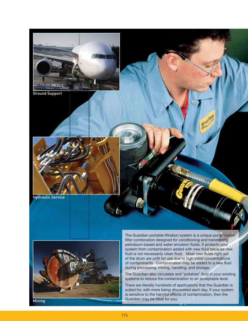
174
Ground Support
Hydraulic Service
Mining
The Guardian portable fi ltration system is a unique pump/motor/fi lter combination designed for conditioning and transferring petroleum-based and water emulsion fl uids. It protects your system from contamination added with new fl uid because new fl uid is not necessarily clean fl uid. Most new fl uids right out of the drum are unfi t for use due to high initial concentrations of contaminants. Contamination may be added to a new fl uid during processing, mixing, handling, and storage.
The Guardian also circulates and “polishes” fl uid in your existing systems to reduce the contamination to an acceptable level.
There are literally hundreds of applications that the Guardian is suited for, with more being discovered each day. If your system is sensitive to the harmful effects of contamination, then the Guardian may be ideal for you.

175
Mobile
Industrial
Marine
Features Advantages Benefi ts
Lightweight, hand held, compact design (less than 24 Ibs 16” X 8” ap-proximate foot print).
Easy to carry and fi ts easily on top of 55 gallon drums.
One person operation, capable of getting to hard to reach areas.
Flow rate to 4 gpm. Filters and transfers simultaneously.
One step operation.
Powerful pump/motor combination with Car-boxylated Nitrile seals standard.
Handles fl uids up to 16,000 SUS viscosity (11,000 SUS -24 VDC).
Reliable performance in a wide variety of operating conditions.
Built-in relief valve with no downstream fl uid bypass.
Only fi ltered fl uid reaches downstream components.
100% fi ltration ensured, even when unattended.
Wide variety of fi lter elements available.
High capacity 2 micron absolute disposable microglass to 74 micron cleanable wire and water removal.
Maximizes element life between changes.
Clear, wire-reinforced 5’ hose assemblies with wand attachments.
No additional hardware required.
Ready to use and easy to maneuver.
Optional quick disconnect hose connections.
Fast, easy setup and tear-down.
Eliminates messy drips.
Heavy-duty ¼ HP, 115 VAC (230 VAC, 24 VDC- optional) motor with thermal overload protection.
UL recognized and CSA listed, with replaceable brushes.
Safe, reliable performance; fi eld serviceable.
Geroter pump with visible serviceable inlet strainer.
Dirt tolerant design with added protection.
Pump reliability in highly contaminated fl uids.
Quiet operation. Less than 70dB noise level @ 3 feet.
Can be used most anywhere with minimal disturbance.
Convenient inlet-to-outlet hose connection.
Contains fl uids when transporting.
Clean and safe operation.
Low center of gravity.
Guardian stability. Unattended reliability.
Dual motor seals. Added motor protection. Longer motor life.
Auxiliary inlet/outlet ports.
Used in place of, or in addition to, standard ports. The outlet can also be used as a sampling port.
Flexibility.
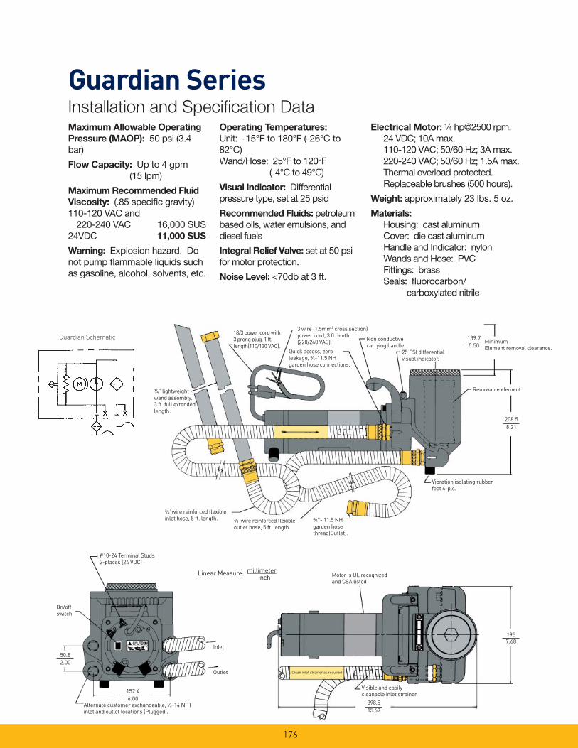
176
Maximum Allowable Operating
Pressure (MAOP): 50 psi (3.4 bar)
Flow Capacity: Up to 4 gpm (15 lpm)
Maximum Recommended Fluid
Viscosity: (.85 specifi c gravity) 110-120 VAC and
220-240 VAC 16,000 SUS24VDC 11,000 SUS
Warning: Explosion hazard. Do not pump fl ammable liquids such as gasoline, alcohol, solvents, etc.
Operating Temperatures:
Unit: -15°F to 180°F (-26°C to 82°C)Wand/Hose: 25°F to 120°F (-4°C to 49°C)
Visual Indicator: Differential pressure type, set at 25 psid
Recommended Fluids: petroleum based oils, water emulsions, and diesel fuels
Integral Relief Valve: set at 50 psi for motor protection.
Noise Level: <70db at 3 ft.
Guardian SeriesInstallation and Specifi cation Data
Electrical Motor: ¼ hp@2500 rpm.24 VDC; 10A max.110-120 VAC; 50/60 Hz; 3A max.220-240 VAC; 50/60 Hz; 1.5A max.Thermal overload protected.Replaceable brushes (500 hours).
Weight: approximately 23 lbs. 5 oz.
Materials:
Housing: cast aluminumCover: die cast aluminumHandle and Indicator: nylon Wands and Hose: PVCFittings: brassSeals: fl uorocarbon/ carboxylated nitrile
18/3 power cord with3 prong plug. 1 ft.length(110/120 VAC).
3 wire (1.5mm2 cross section)power cord, 3 ft. lenth(220/240 VAC).
Quick access, zeroleakage, ¾-11.5 NHgarden hose connections.
Non conductivecarrying handle.
MinimumElement removal clearance.
Removable element.
139.7
5.50
Vibration isolating rubberfeet 4-pls.
¾”wire reinforced fl exibleinlet hose, 5 ft. length. ¾”wire reinforced fl exible
outlet hose, 5 ft. length.
¾”- 11.5 NH garden hose thread(Outlet).
25 PSI differentialvisual indicator.
208.5
8.21
¾” lightweight wand assembly, 3 ft. full extended length.
#10-24 Terminal Studs2-places (24 VDC)
On/offswitch
50.8
2.00
152.4
6.00Alternate customer exchangeable, ½-14 NPT inlet and outlet locations (Plugged).
Inlet
Outlet
1957.68
Motor is UL recognizedand CSA listed
398.5
15.69
Visible and easilycleanable inlet strainer
Clean inlet strainer as required
Linear Measure: millimeterinch
Guardian Schematic
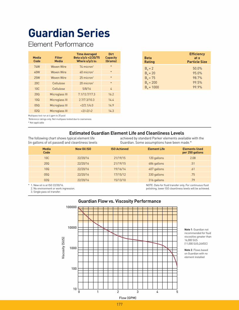
177
MediaCode
New Oil ISO ISO Achieved Element Life Elements Used per 250 gallons
10C 22/20/16 21/19/15 120 gallons 2.08
20Q 22/20/16 21/19/15 486 gallons .51
10Q 22/20/16 19/16/14 407 gallons .61
05Q 22/20/16 17/15/12 330 gallons .75
02Q 22/20/16 15/13/10 316 gallons .79
Mining
Note 1: Guardian not
recommended for fl uid
viscosities greater than
16,000 SUS
(11,000 SUS;24VDC)
Note 2: Flows based
on Guardian with no
element installed
Bx = 2 50.0%
Bx = 20 95.0%
Bx = 75 98.7%
Bx = 200 99.5%
Bx = 1000 99.9%
Effi ciencyBeta at xRating Particle Size
Guardian Flow vs. Viscosity Performance
Multipass test run at 4 gpm to 35 psid1Reference ratings only. Not multipass tested due to coarseness.
* Not applicable
Estimated Guardian Element Life and Cleanliness LevelsThe following chart shows typical element life (in gallons of oil passed) and cleanliness levels
achieved by standard Parker elements available with the Guardian. Some assumptions have been made.*
* 1. New oil is at ISO 22/20/16. 2. No environment or work ingression. 3. Single pass oil transfer.
NOTE: Data for fl uid transfer only. For continuous fl uid polishing, lower ISO cleanliness levels will be achieved.
100000
10000
10
1000
100
0 1 2 3 4 5
Visc
osity
(SU
S)
Flow (GPM)
MediaCode
FilterMedia
Time AveragedBeta x/y/z =2/20/75
Where x/y/z is:
DirtCapacity(Grams)
74W Woven Wire 74 micron1 *
40W Woven Wire 40 micron1 *
25W Woven Wire 25 micron1 *
20C Cellulose 20 micron1 *
10C Cellulose 5/8/16 4
20Q Microglass III 7.1/13.7/17.3 16.2
10Q Microglass III 2.7/7.3/10.3 14.4
05Q Microglass III <2/2.1/4.0 14.9
02Q Microglass III <2/<2/<2 14.3
Guardian SeriesElement Performance
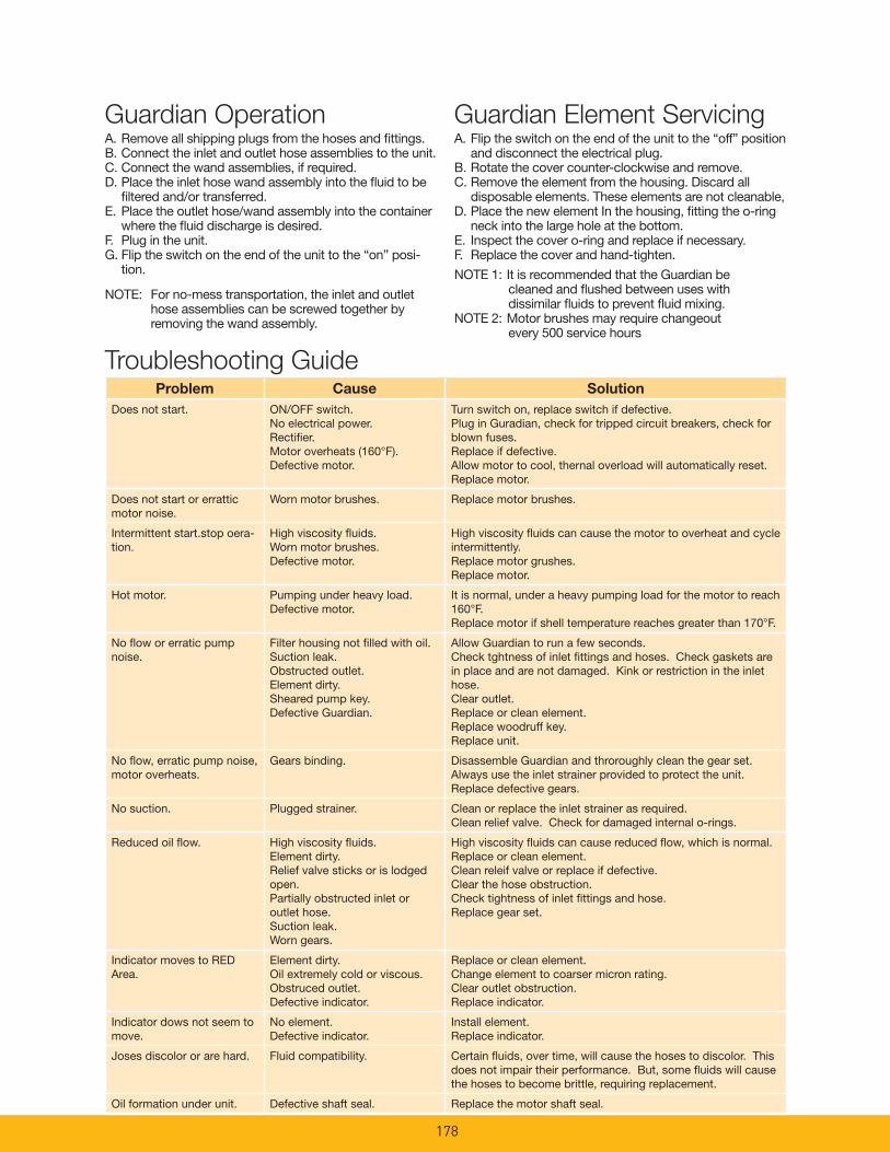
178
Guardian OperationA. Remove all shipping plugs from the hoses and fi ttings.B. Connect the inlet and outlet hose assemblies to the unit.C. Connect the wand assemblies, if required. D. Place the inlet hose wand assembly into the fl uid to be
fi ltered and/or transferred. E. Place the outlet hose/wand assembly into the container
where the fl uid discharge is desired. F. Plug in the unit. G. Flip the switch on the end of the unit to the “on” posi-
tion.
NOTE: For no-mess transportation, the inlet and outlet hose assemblies can be screwed together by removing the wand assembly.
Guardian Element ServicingA. Flip the switch on the end of the unit to the “off” position
and disconnect the electrical plug.B. Rotate the cover counter-clockwise and remove.C. Remove the element from the housing. Discard all
disposable elements. These elements are not cleanable,D. Place the new element In the housing, fi tting the o-ring
neck into the large hole at the bottom.E. Inspect the cover o-ring and replace if necessary.F. Replace the cover and hand-tighten.
NOTE 1: It is recommended that the Guardian be cleaned and fl ushed between uses with dissimilar fl uids to prevent fl uid mixing.
NOTE 2: Motor brushes may require changeout every 500 service hours
Problem Cause Solution
Does not start. ON/OFF switch.No electrical power.Rectifi er.Motor overheats (160°F).Defective motor.
Turn switch on, replace switch if defective.Plug in Guradian, check for tripped circuit breakers, check for blown fuses.Replace if defective.Allow motor to cool, thernal overload will automatically reset.Replace motor.
Does not start or errattic motor noise.
Worn motor brushes. Replace motor brushes.
Intermittent start.stop oera-tion.
High viscosity fl uids.Worn motor brushes.Defective motor.
High viscosity fl uids can cause the motor to overheat and cycle intermittently.Replace motor grushes.Replace motor.
Hot motor. Pumping under heavy load.Defective motor.
It is normal, under a heavy pumping load for the motor to reach 160°F.Replace motor if shell temperature reaches greater than 170°F.
No fl ow or erratic pump noise.
Filter housing not fi lled with oil.Suction leak.Obstructed outlet.Element dirty.Sheared pump key.Defective Guardian.
Allow Guardian to run a few seconds.Check tghtness of inlet fi ttings and hoses. Check gaskets are in place and are not damaged. Kink or restriction in the inlet hose.Clear outlet.Replace or clean element.Replace woodruff key.Replace unit.
No fl ow, erratic pump noise, motor overheats.
Gears binding. Disassemble Guardian and throroughly clean the gear set.Always use the inlet strainer provided to protect the unit.Replace defective gears.
No suction. Plugged strainer. Clean or replace the inlet strainer as required.Clean relief valve. Check for damaged internal o-rings.
Reduced oil fl ow. High viscosity fl uids.Element dirty.Relief valve sticks or is lodged open.Partially obstructed inlet or outlet hose.Suction leak.Worn gears.
High viscosity fl uids can cause reduced fl ow, which is normal.Replace or clean element.Clean releif valve or replace if defective.Clear the hose obstruction.Check tightness of inlet fi ttings and hose.Replace gear set.
Indicator moves to RED Area.
Element dirty.Oil extremely cold or viscous.Obstruced outlet.Defective indicator.
Replace or clean element.Change element to coarser micron rating.Clear outlet obstruction.Replace indicator.
Indicator dows not seem to move.
No element.Defective indicator.
Install element.Replace indicator.
Joses discolor or are hard. Fluid compatibility. Certain fl uids, over time, will cause the hoses to discolor. This does not impair their performance. But, some fl uids will cause the hoses to become brittle, requiring replacement.
Oil formation under unit. Defective shaft seal. Replace the motor shaft seal.
Troubleshooting Guide
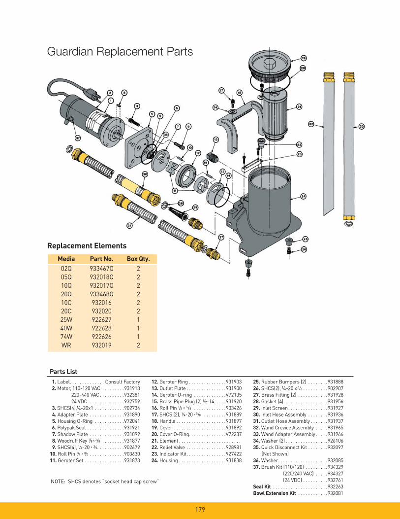
179
Replacement Elements
Media Part No. Box Qty. 02Q 933467Q 2
05Q 932018Q 2
10Q 932017Q 2
20Q 933468Q 2
10C 932016 2
20C 932020 2
25W 922627 1
40W 922628 1
74W 922626 1
WR 932019 2
Parts List 1. Label . . . . . . . . . . . . . . Consult Factory
2. Motor, 110-120 VAC . . . . . . . . .931913
220-440 VAC . . . . . . . . . .932381
24 VDC . . . . . . . . . . . . . . .932759
3. SHCS(4),¼-20x1 . . . . . . . . . . . .902734
4. Adapter Plate . . . . . . . . . . . . . .931890
5. Housing O-Ring . . . . . . . . . . . .V72041
6. Polypak Seal . . . . . . . . . . . . . . .931921
7. Shadow Plate . . . . . . . . . . . . . .931899
8. Woodruff Key 1/8 x 3/8 . . . . . . . . .931877
9. SHCS(4), ¼-20 x ¾ . . . . . . . . . .902679
10. Roll Pin 1/8 x ¾ . . . . . . . . . . . . . .903630
11. Geroter Set . . . . . . . . . . . . . . . .931873
12. Geroter Ring . . . . . . . . . . . . . . .931903
13. Outlet Plate . . . . . . . . . . . . . . . .931900
14. Geroter O-ring . . . . . . . . . . . . .V72135
15. Brass Pipe Plug (2) ½-14. . . . .931920
16. RoIl Pin 1/8 x 5/8 . . . . . . . . . . . . .903426
17. SHCS (2), ¼-20 x 5/8 . . . . . . . . .931889
18. Handle . . . . . . . . . . . . . . . . . . . .931897
19. Cover . . . . . . . . . . . . . . . . . . . . .931892
20. Cover O-Ring . . . . . . . . . . . . . . .V72237
21. Element . . . . . . . . . . . . . . . . . . . . . . . . .
22. Relief Valve . . . . . . . . . . . . . . . .928981
23. Indicator Kit . . . . . . . . . . . . . . . .927422
24. Housing . . . . . . . . . . . . . . . . . . .931838
25. Rubber Bumpers (2) . . . . . . . .931888
26. SHCS(2), ¼-20 x ½ . . . . . . . . . .902907
27. Brass Fitting (2) . . . . . . . . . . . .931928
28. Gasket (4). . . . . . . . . . . . . . . . . .931956
29. Inlet Screen . . . . . . . . . . . . . . . .931927
30. Inlet Hose Assembly . . . . . . . .931936
31. Outlet Hose Assembly . . . . . . .931937
32. Wand Crevice Assembly . . . . .931965
33. Wand Adapter Assembly . . . . .931966
34. Washer (2) . . . . . . . . . . . . . . . . .926106
35. Quick Disconnect Kit . . . . . . . .932097
(Not Shown)
36. Washer . . . . . . . . . . . . . . . . . . . .932085
37. Brush Kit (110/120) . . . . . . . . .934329
(220/240 VAC) . . . . .934327
(24 VDC) . . . . . . . . . .932761
Seal Kit . . . . . . . . . . . . . . . . . . . . . .932263
Bowl Extension Kit . . . . . . . . . . . .932081
NOTE: SHCS denotes “socket head cap screw”
Guardian Replacement Parts
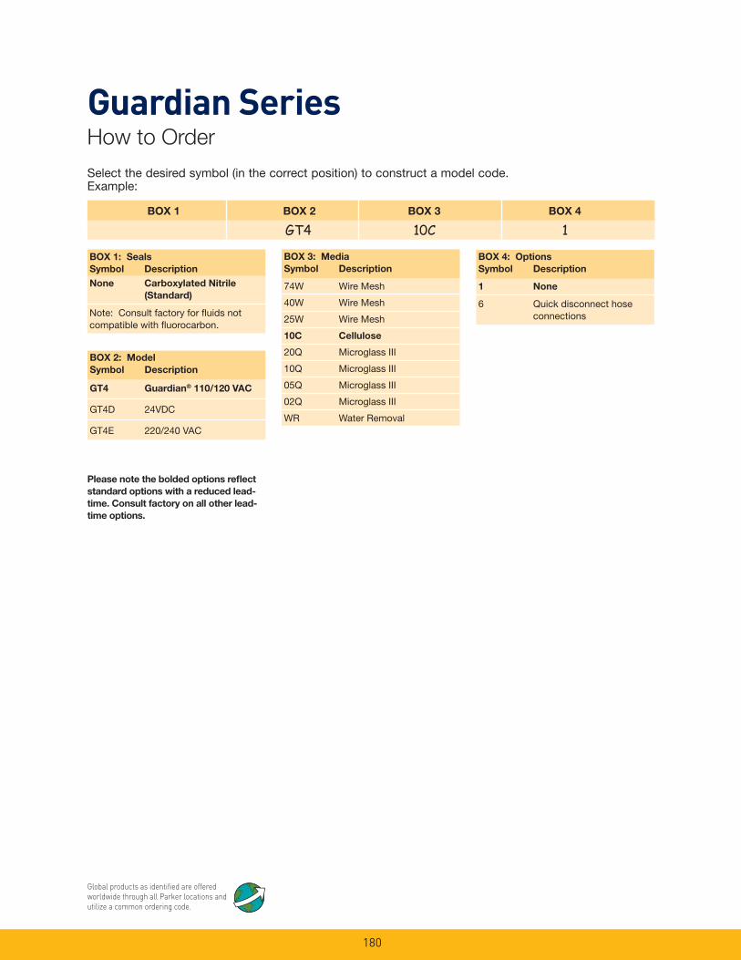
180
Please note the bolded options refl ect
standard options with a reduced lead-
time. Consult factory on all other lead-
time options.
Select the desired symbol (in the correct position) to construct a model code. Example:
BOX 1 BOX 2 BOX 3 BOX 4
GT4 10C 1
BOX 1: Seals
Symbol Description
None Carboxylated Nitrile
(Standard)
Note: Consult factory for fl uids not compatible with fl uorocarbon.
BOX 3: Media
Symbol Description
74W Wire Mesh
40W Wire Mesh
25W Wire Mesh
10C Cellulose
20Q Microglass III
10Q Microglass III
05Q Microglass III
02Q Microglass III
WR Water Removal
BOX 2: Model
Symbol Description
GT4 Guardian® 110/120 VAC
GT4D 24VDC
GT4E 220/240 VAC
BOX 4: Options
Symbol Description
1 None
6 Quick disconnect hose connections
Guardian SeriesHow to Order
Global products as identifi ed are offered worldwide through all Parker locations and utilize a common ordering code.
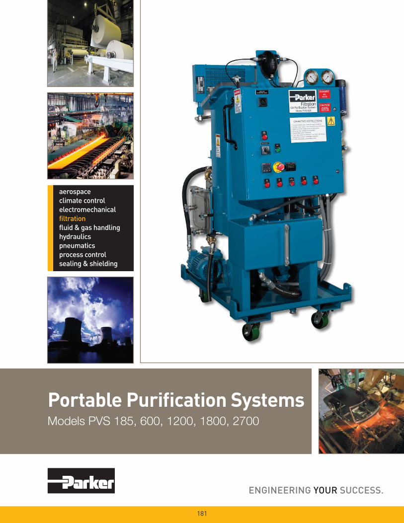
Portable Purifi cation SystemsModels PVS 185, 600, 1200, 1800, 2700
181

PVS SeriesPrinciples of Operation
Contaminated oil is drawn into the Parker Portable Purifi cation System by a vacuum of 25 In/Hg. The oil passes through the in-line low watt density heater where the oil is heated to an optimum temperature of 150° F (66°C).
The oil then enters the distillation column where it is exposed to the vacuum through the use of special dispersal elements. This increases the exposed surface area of the oil and converts the water to vapor form, which is then drawn through the condenser by the vacuum pump.
The water-free oil falls to the bottom of the column and is removed by a heavy duty lube oil pump. This pump forces the dry oil through a fi nal particulate removal fi lter. Clean oil passes out of the unit, back to the reservoir — and into the system.
Free water occurs when oil becomes saturated and cannot hold any more water. This water is usually seen as cloudy oil or puddles of water at the bottom of an oil reservoir. Water which is absorbed into the oil is called dissolved water. At higher temperatures, oil has the ability to hold more water in the dissolved stage due to the ex pan sion of oil mol e cules. As the oil cools, this ability reverses and free water will appear where not visible before. In addition to tem per a ture, fl uid type also determines the saturation point for your system (see chart above).
Effects of Water Con tam i na tion
Water is one of the most common con tam i nants in a fl uid system and one of the most damaging. When water con tam i nates a system, it can cause serious problems such as:
• Corrosion by etching metal
• Fluid breakdown, reduction of lubricating properties, additive precipitation, and oil oxidation
• Reduced dielectric strength
• Abrasive wear in hydraulic components
Typical Saturation Points
Fluid Type PPM %
Hydraulic Fluid 300 .03%
Lubrication Fluid 400 .04%
Transformer Fluid 50 .005%
182
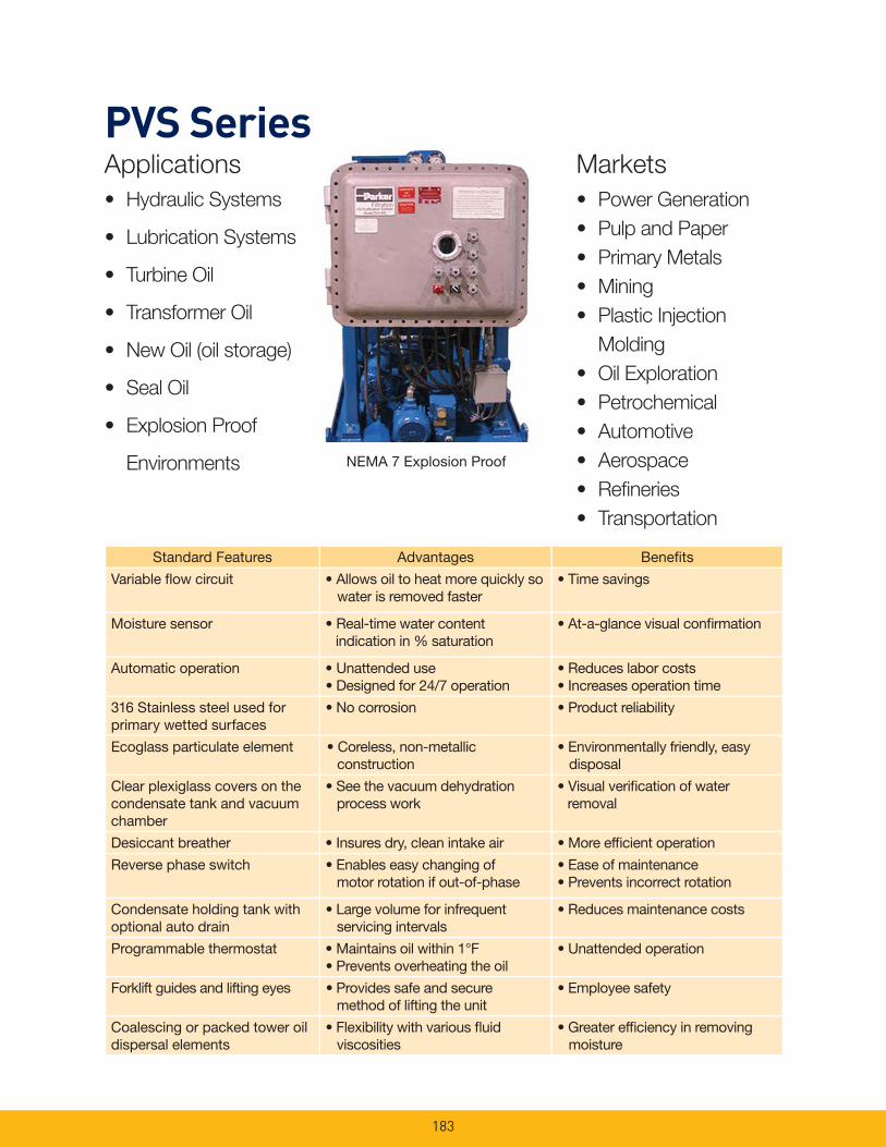
183
PVS SeriesApplications
• Hydraulic Systems
• Lubrication Systems
• Turbine Oil
• Transformer Oil
• New Oil (oil storage)
• Seal Oil
• Explosion Proof
Environments
Standard Features Advantages Benefi ts
Variable fl ow circuit • Allows oil to heat more quickly so water is removed faster
• Time savings
Moisture sensor • Real-time water content indication in % saturation
• At-a-glance visual confi rmation
Automatic operation • Unattended use • Designed for 24/7 operation
• Reduces labor costs • Increases operation time
316 Stainless steel used for primary wetted surfaces
• No corrosion • Product reliability
Ecoglass particulate element • Coreless, non-metallic construction
• Environmentally friendly, easy disposal
Clear plexiglass covers on the condensate tank and vacuum chamber
• See the vacuum dehydration process work
• Visual verifi cation of water removal
Desiccant breather • Insures dry, clean intake air • More effi cient operation
Reverse phase switch • Enables easy changing of motor rotation if out-of-phase
• Ease of maintenance• Prevents incorrect rotation
Condensate holding tank with optional auto drain
• Large volume for infrequent servicing intervals
• Reduces maintenance costs
Programmable thermostat • Maintains oil within 1°F• Prevents overheating the oil
• Unattended operation
Forklift guides and lifting eyes • Provides safe and secure method of lifting the unit
• Employee safety
Coalescing or packed tower oil dispersal elements
• Flexibility with various fl uid viscosities
• Greater effi ciency in removing moisture
• Power Generation
• Pulp and Paper
• Primary Metals
• Mining
• Plastic Injection
Molding
• Oil Exploration
• Petrochemical
• Automotive
• Aerospace
• Refi neries
• Transportation
Markets
NEMA 7 Explosion Proof

184
Typical Performance
Tank Size 60 Gallons (227 liters)
Run Time 62 minutes
Parker Model PVS 600 (10 GPM)
Water Content (ppm) Start: 10,000 PPM (1.0%)Stop: 50 PPM (0.005%)
Contamination Level Start: ISO 21/18/16Stop: ISO 16/14/11
Start Stop
PVS Series Vacuum Dehydration Performance
PVS (Vacuum De hy dra tion)
Compared to Other TechnologiesCentrifuge units – Removes free water only; has diffi -culty breaking stable emulsions; larger envelope dimen-sions but lower fl ows; higher initial and operating costs.
Desiccant units – Have limited water removal capability due to absorbing material; only removes air ingressed particles; ex pen sive compared to the volume of water removed.
Coalescer units – Removes free water only; has dif-fi culty breaking stable emulsions; does not work well in viscous fl uids (>100 sus); much larger in size compared to PVS.
Potential
Contaminant PVS Performance
Solid particulateISO Cleanliness Code*14/13/10 Attainable
WaterRemoves 100% of free water, 90% of dissolved water
Air/GasesRemoves 100% of free air and gases, 90% of dissolved air and gases
*When utilizing 02Q media.

185
PVS 185 SeriesSpecifi cations
PVS 185 Flow Diagram
Heater
Standard CorelessParticulate (80CN-2)
02QE (2 micron) 936716Q
05QE (5 micron) 936717Q
10QE (10 micron) 936718Q
20QE (20 micron) 936719Q
Optional CorelessParticulate (IL8-3)
02QE (2 micron) 933734Q
05QE (5 micron) 933612Q
10QE (10 micron) 933735Q
20QE (20 micron) 933736Q
Dispersal
Disposable(Coalescing)
933180
Packed tower (Cleanable)
933553
Replacement
Elements
Note: Dimensions and weights are approximate and for reference only.
UL and CUL Marked
Flow rate 5 gpm (18.9 lpm)
Dimensions 65" H x 33” W x 48” L
(1651mm x 838mm x 1219mm)
Weight 650 lbs. (295 kg)
Seal material Fluorocarbon (EPR optional)
Condensate tank 4.1 gal (15.5 ltrs)
Dispersal elements 1
Minimum operating capacity 5 gal (18.9 ltrs)
Vacuum (max) 25 In/Hg
Viscosity (max) 500 sus (108 cSt)-Disposable
2150 sus (460 cSt)-Packed Tower
Outlet pressure (max) 60 psi (4.1 bar)
Ports 3/4" JIC (male) inlet
3/4" JIC (male) outlet
FLA (full load amps) 15-41 amps
(Depending on options & voltages)
Shipping Weight 1400 lbs. (635 kg) maximum
Shipping Dimensions 70” H x 48” W x 60” L
(1778mm x 1219mm x 1524mm)
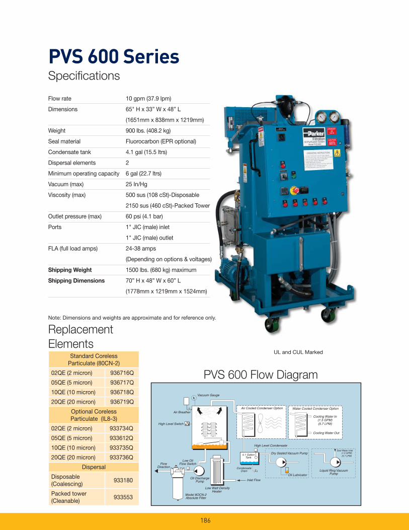
186
PVS 600 SeriesSpecifi cations
PVS 600 Flow Diagram
Standard CorelessParticulate (80CN-2)
02QE (2 micron) 936716Q
05QE (5 micron) 936717Q
10QE (10 micron) 936718Q
20QE (20 micron) 936719Q
Optional CorelessParticulate (IL8-3)
02QE (2 micron) 933734Q
05QE (5 micron) 933612Q
10QE (10 micron) 933735Q
20QE (20 micron) 933736Q
Dispersal
Disposable(Coalescing)
933180
Packed tower (Cleanable)
933553
Replacement
Elements
Note: Dimensions and weights are approximate and for reference only.
UL and CUL Marked
Flow rate 10 gpm (37.9 lpm)
Dimensions 65" H x 33” W x 48” L
(1651mm x 838mm x 1219mm)
Weight 900 lbs. (408.2 kg)
Seal material Fluorocarbon (EPR optional)
Condensate tank 4.1 gal (15.5 ltrs)
Dispersal elements 2
Minimum operating capacity 6 gal (22.7 ltrs)
Vacuum (max) 25 In/Hg
Viscosity (max) 500 sus (108 cSt)-Disposable
2150 sus (460 cSt)-Packed Tower
Outlet pressure (max) 60 psi (4.1 bar)
Ports 1" JIC (male) inlet
1" JIC (male) outlet
FLA (full load amps) 24-38 amps
(Depending on options & voltages)
Shipping Weight 1500 lbs. (680 kg) maximum
Shipping Dimensions 70” H x 48” W x 60” L
(1778mm x 1219mm x 1524mm)
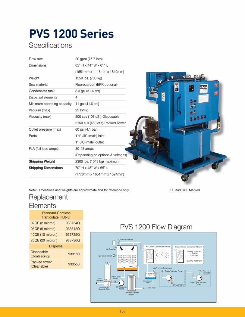
187
PVS 1200 SeriesSpecifi cations
PVS 1200 Flow Diagram
Standard CorelessParticulate (IL8-3)
02QE (2 micron) 933734Q
05QE (5 micron) 933612Q
10QE (10 micron) 933735Q
20QE (20 micron) 933736Q
Dispersal
Disposable(Coalescing)
933180
Packed tower (Cleanable)
933553
Replacement
Elements
Note: Dimensions and weights are approximate and for reference only. UL and CUL Marked
Flow rate 20 gpm (75.7 lpm)
Dimensions 65" H x 44” W x 61” L
(1651mm x 1118mm x 1549mm)
Weight 1550 lbs. (703 kg)
Seal material Fluorocarbon (EPR optional)
Condensate tank 8.3 gal (31.4 ltrs)
Dispersal elements 4
Minimum operating capacity 11 gal (41.6 ltrs)
Vacuum (max) 25 In/Hg
Viscosity (max) 500 sus (108 cSt)-Disposable
2150 sus (460 cSt)-Packed Tower
Outlet pressure (max) 60 psi (4.1 bar)
Ports 1½" JIC (male) inlet
1" JIC (male) outlet
FLA (full load amps) 30-48 amps
(Depending on options & voltages)
Shipping Weight 2300 lbs. (1043 kg) maximum
Shipping Dimensions 70” H x 48” W x 65” L
(1778mm x 1651mm x 1524mm)
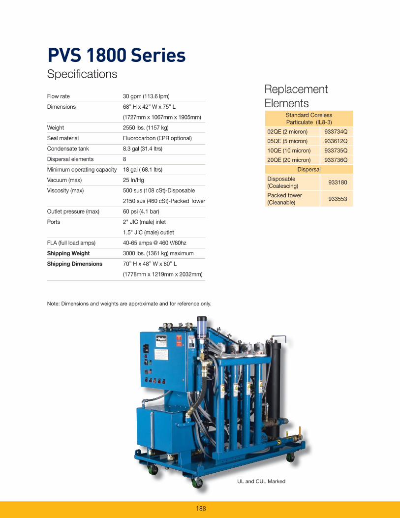
188
PVS 1800 SeriesSpecifi cations
Replacement
ElementsStandard CorelessParticulate (IL8-3)
02QE (2 micron) 933734Q
05QE (5 micron) 933612Q
10QE (10 micron) 933735Q
20QE (20 micron) 933736Q
Dispersal
Disposable(Coalescing)
933180
Packed tower (Cleanable)
933553
Note: Dimensions and weights are approximate and for reference only.
UL and CUL Marked
Flow rate 30 gpm (113.6 lpm)
Dimensions 68” H x 42” W x 75” L
(1727mm x 1067mm x 1905mm)
Weight 2550 lbs. (1157 kg)
Seal material Fluorocarbon (EPR optional)
Condensate tank 8.3 gal (31.4 ltrs)
Dispersal elements 8
Minimum operating capacity 18 gal ( 68.1 ltrs)
Vacuum (max) 25 In/Hg
Viscosity (max) 500 sus (108 cSt)-Disposable
2150 sus (460 cSt)-Packed Tower
Outlet pressure (max) 60 psi (4.1 bar)
Ports 2" JIC (male) inlet
1.5" JIC (male) outlet
FLA (full load amps) 40-65 amps @ 460 V/60hz
Shipping Weight 3000 lbs. (1361 kg) maximum
Shipping Dimensions 70” H x 48” W x 80” L
(1778mm x 1219mm x 2032mm)
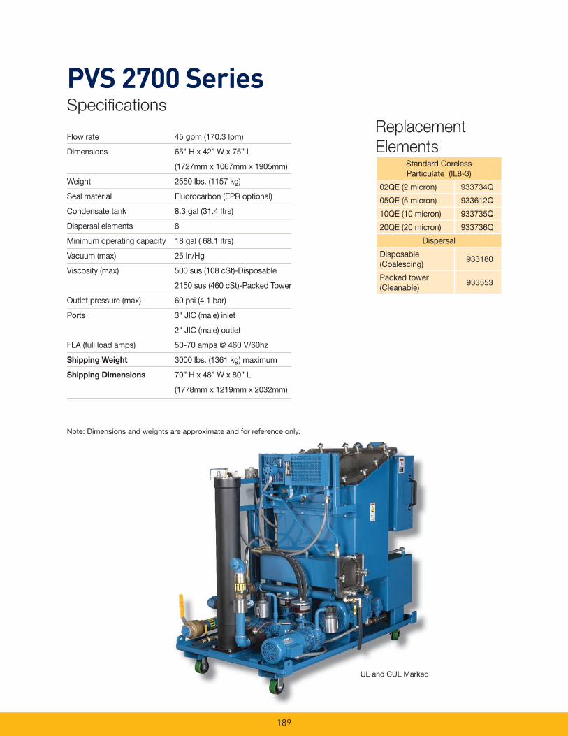
189
PVS 2700 SeriesSpecifi cations
Standard CorelessParticulate (IL8-3)
02QE (2 micron) 933734Q
05QE (5 micron) 933612Q
10QE (10 micron) 933735Q
20QE (20 micron) 933736Q
Dispersal
Disposable(Coalescing)
933180
Packed tower (Cleanable)
933553
Replacement
Elements
Note: Dimensions and weights are approximate and for reference only.
UL and CUL Marked
Flow rate 45 gpm (170.3 lpm)
Dimensions 65" H x 42” W x 75” L
(1727mm x 1067mm x 1905mm)
Weight 2550 lbs. (1157 kg)
Seal material Fluorocarbon (EPR optional)
Condensate tank 8.3 gal (31.4 ltrs)
Dispersal elements 8
Minimum operating capacity 18 gal ( 68.1 ltrs)
Vacuum (max) 25 In/Hg
Viscosity (max) 500 sus (108 cSt)-Disposable
2150 sus (460 cSt)-Packed Tower
Outlet pressure (max) 60 psi (4.1 bar)
Ports 3" JIC (male) inlet
2" JIC (male) outlet
FLA (full load amps) 50-70 amps @ 460 V/60hz
Shipping Weight 3000 lbs. (1361 kg) maximum
Shipping Dimensions 70” H x 48” W x 80” L
(1778mm x 1219mm x 2032mm)
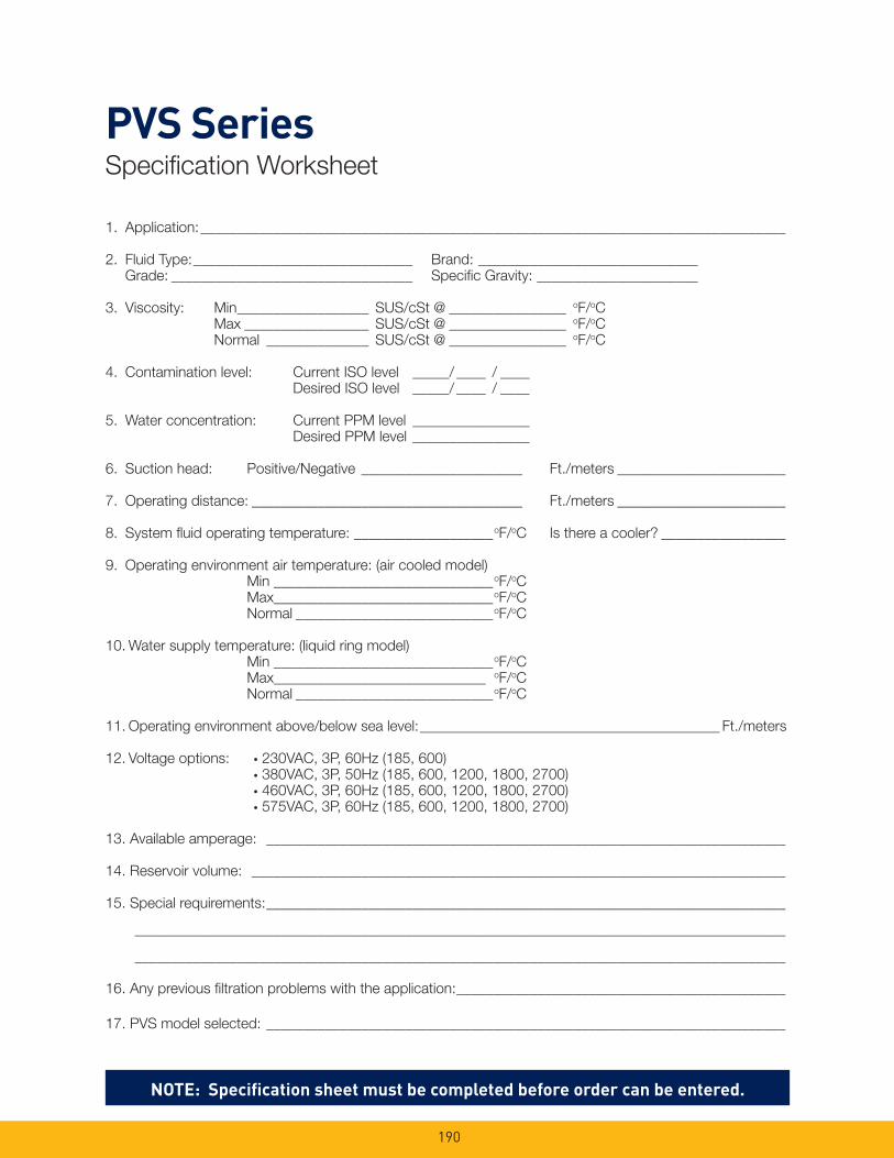
190
1. Application: ________________________________________________________________________________
2. Fluid Type: ______________________________ Brand: ______________________________ Grade: _________________________________ Specifi c Gravity: ______________________
3. Viscosity: Min __________________ SUS/cSt @ ________________ oF/oC Max _________________ SUS/cSt @ ________________ oF/oC Normal ______________ SUS/cSt @ ________________ oF/oC
4. Contamination level: Current ISO level _____/ ____ / ____ Desired ISO level _____/ ____ / ____
5. Water concentration: Current PPM level ________________ Desired PPM level ________________
6. Suction head: Positive/Negative ______________________ Ft./meters _______________________
7. Operating distance: _____________________________________ Ft./meters _______________________
8. System fl uid operating temperature: ___________________oF/oC Is there a cooler? _________________
9. Operating environment air temperature: (air cooled model) Min ______________________________oF/oC Max______________________________oF/oC Normal ___________________________oF/oC
10. Water supply temperature: (liquid ring model) Min ______________________________oF/oC Max_____________________________ oF/oC Normal ___________________________oF/oC
11. Operating environment above/below sea level: _________________________________________ Ft./meters
12. Voltage options: • 230VAC, 3P, 60Hz (185, 600) • 380VAC, 3P, 50Hz (185, 600, 1200, 1800, 2700) • 460VAC, 3P, 60Hz (185, 600, 1200, 1800, 2700) • 575VAC, 3P, 60Hz (185, 600, 1200, 1800, 2700)
13. Available amperage: _______________________________________________________________________
14. Reservoir volume: _________________________________________________________________________
15. Special requirements: _______________________________________________________________________
_________________________________________________________________________________________
_________________________________________________________________________________________
16. Any previous fi ltration problems with the application: _____________________________________________
17. PVS model selected: _______________________________________________________________________
NOTE: Specifi cation sheet must be completed before order can be entered.
PVS SeriesSpecifi cation Worksheet
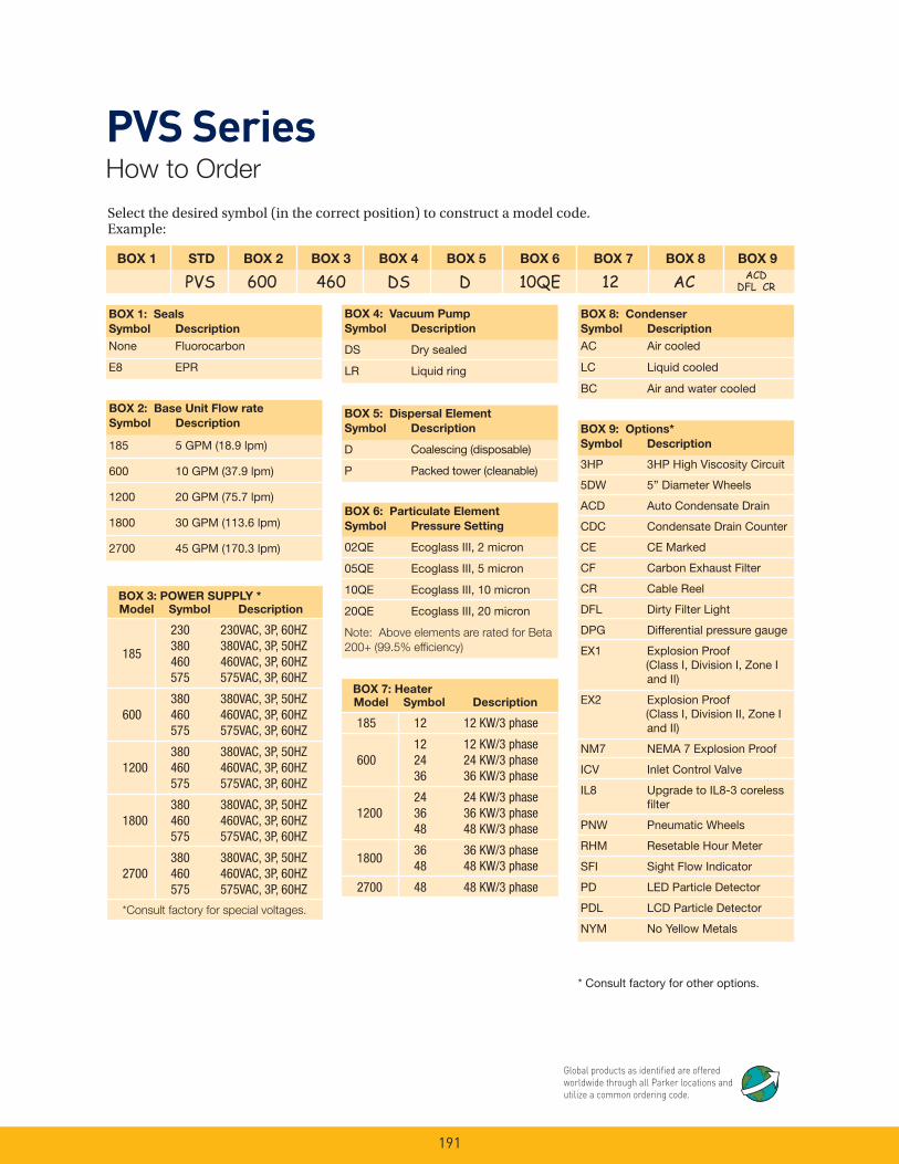
191
Select the desired symbol (in the correct position) to construct a model code. Example:
BOX 1 STD BOX 2 BOX 3 BOX 4 BOX 5 BOX 6 BOX 7 BOX 8 BOX 9
PVS 600 460 DS D 10QE 12 AC ACD
DFL CR
BOX 1: Seals
Symbol Description
None Fluorocarbon
E8 EPR
BOX 5: Dispersal Element
Symbol Description
D Coalescing (disposable)
P Packed tower (cleanable)
BOX 4: Vacuum Pump
Symbol Description
DS Dry sealed
LR Liquid ring
BOX 9: Options*
Symbol Description
3HP 3HP High Viscosity Circuit
5DW 5” Diameter Wheels
ACD Auto Condensate Drain
CDC Condensate Drain Counter
CE CE Marked
CF Carbon Exhaust Filter
CR Cable Reel
DFL Dirty Filter Light
DPG Differential pressure gauge
EX1 Explosion Proof (Class I, Division I, Zone I and II)
EX2 Explosion Proof (Class I, Division II, Zone I and II)
NM7 NEMA 7 Explosion Proof
ICV Inlet Control Valve
IL8 Upgrade to IL8-3 coreless fi lter
PNW Pneumatic Wheels
RHM Resetable Hour Meter
SFI Sight Flow Indicator
PD LED Particle Detector
PDL LCD Particle Detector
NYM No Yellow Metals
BOX 2: Base Unit Flow rate
Symbol Description
185 5 GPM (18.9 lpm)
600 10 GPM (37.9 lpm)
1200 20 GPM (75.7 lpm)
1800 30 GPM (113.6 lpm)
2700 45 GPM (170.3 lpm)
BOX 6: Particulate Element
Symbol Pressure Setting
02QE Ecoglass III, 2 micron
05QE Ecoglass III, 5 micron
10QE Ecoglass III, 10 micron
20QE Ecoglass III, 20 micron
Note: Above elements are rated for Beta
200+ (99.5% effi ciency)
PVS SeriesHow to Order
Global products as identifi ed are offered worldwide through all Parker locations and utilize a common ordering code.
BOX 7: Heater
Model Symbol Description
185 12 12 KW/3 phase
60012 12 KW/3 phase24 24 KW/3 phase36 36 KW/3 phase
120024 24 KW/3 phase36 36 KW/3 phase48 48 KW/3 phase
180036 36 KW/3 phase48 48 KW/3 phase
2700 48 48 KW/3 phase
BOX 8: Condenser
Symbol Description
AC Air cooled
LC Liquid cooled
BC Air and water cooled
* Consult factory for other options.
BOX 3: POWER SUPPLY *
Model Symbol Description
185
230 230VAC, 3P, 60HZ380 380VAC, 3P, 50HZ460 460VAC, 3P, 60HZ575 575VAC, 3P, 60HZ
600380 380VAC, 3P, 50HZ460 460VAC, 3P, 60HZ575 575VAC, 3P, 60HZ
1200380 380VAC, 3P, 50HZ460 460VAC, 3P, 60HZ575 575VAC, 3P, 60HZ
1800380 380VAC, 3P, 50HZ460 460VAC, 3P, 60HZ575 575VAC, 3P, 60HZ
2700380 380VAC, 3P, 50HZ460 460VAC, 3P, 60HZ575 575VAC, 3P, 60HZ
*Consult factory for special voltages.

Notes
192

SMR SeriesSubmicronic Removal
Fluid Purifi cation Systems
193

194
SMR SeriesApplications
The SMR Series is the smart purifi cation solution for fl uid fl ow in the 2-10 GPM (8 - 38 LPM) range. The SMR contains patented Balanced Charge Agglomeration (BCA™) technology, which maintains hydraulic and lubricating fl uids in optimum condition while preventing/removing the build-up of sludge and varnish. The system is available in a PLC or simplifi ed control version.
• Power Generation
- Steam & Gas Turbine - hydraulics & lubrication• Oil & Gas
- Compressor/Turbine hydraulics & lubrication• Pulp & Paper
- Lube oil - Hydraulics• Manufacturing
- Hydraulics - Lubrication - EDM - Injection molders• Others
- Cooking oil - Gear oil - Fuels - Bio fuels - Steel - Military
Balanced Charge Agglomeration (BCA™) technology does not remove water, however with the removal of thousands of sub-micron particles, the majority of sites where water can readily attach are mitigated. Water is more easily separated and removed, improving demulsibility.
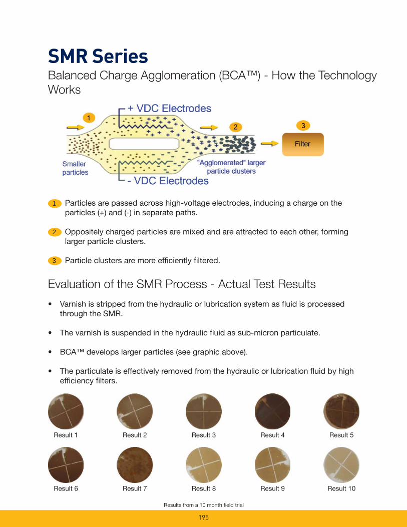
195
SMR SeriesBalanced Charge Agglomeration (BCA™) - How the Technology
Works
1 Particles are passed across high-voltage electrodes, inducing a charge on the particles (+) and (-) in separate paths.
Oppositely charged particles are mixed and are attracted to each other, forming larger particle clusters.
Particle clusters are more effi ciently fi ltered.
2
3
• Varnish is stripped from the hydraulic or lubrication system as fl uid is processed through the SMR.
• The varnish is suspended in the hydraulic fl uid as sub-micron particulate.
• BCA™ develops larger particles (see graphic above).
• The particulate is effectively removed from the hydraulic or lubrication fl uid by high effi ciency fi lters.
Evaluation of the SMR Process - Actual Test Results
Result 1 Result 2 Result 3 Result 4 Result 5
Result 6 Result 7 Result 8 Result 9 Result 10
Results from a 10 month fi eld trial
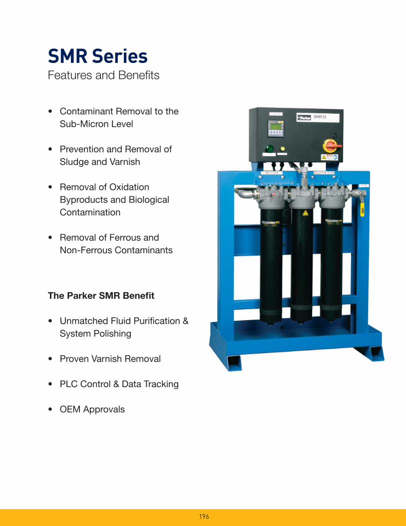
196
SMR SeriesFeatures and Benefi ts
• Contaminant Removal to the Sub-Micron Level
• Prevention and Removal of Sludge and Varnish
• Removal of Oxidation Byproducts and Biological Contamination
• Removal of Ferrous and Non-Ferrous Contaminants
The Parker SMR Benefi t
• Unmatched Fluid Purifi cation & System Polishing
• Proven Varnish Removal
• PLC Control & Data Tracking
• OEM Approvals
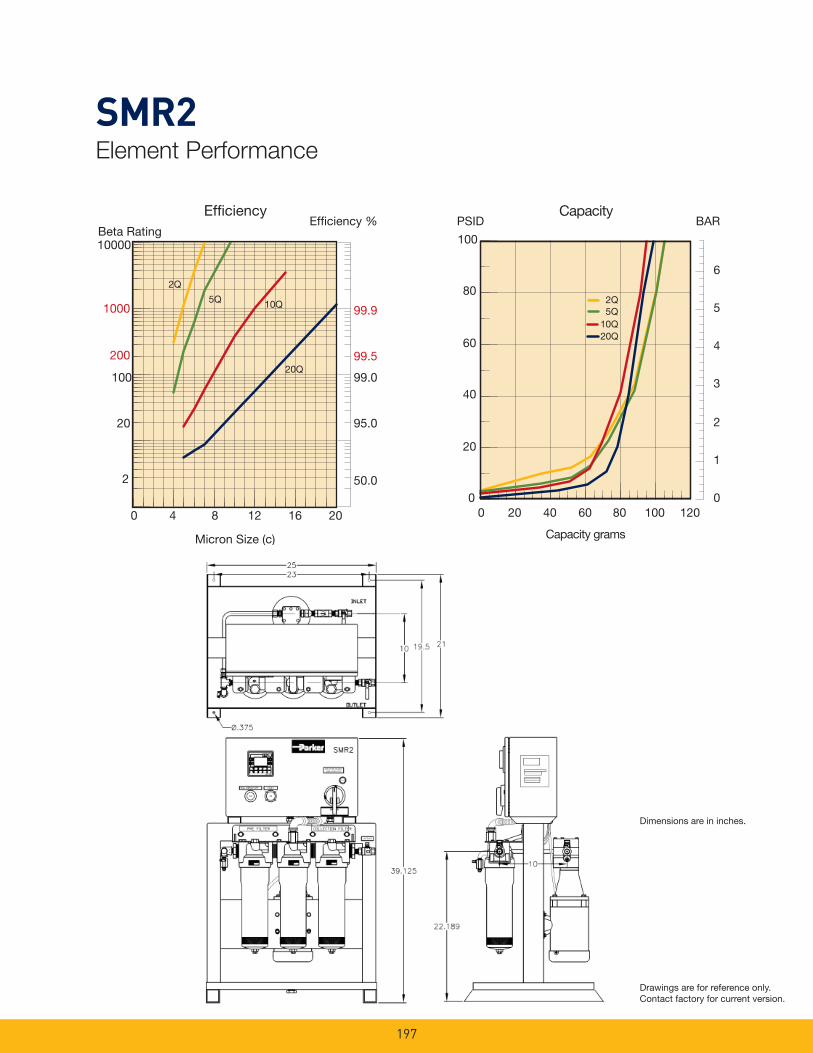
197
SMR2Element Performance
EfficiencyBeta Rating
1000
10000
99.9
99.5
99.0100
200
20
2 50.0
95.0
5Q 10Q
20Q
2Q
0 4 8 12 16 20
Micron Size (c)
Efficiency % PSID BARCapacity
2Q
10Q20Q
5Q
0
1
2
3
4
5
6
0
20
40
60
80
100
0 20 40 60 80 100 120
Capacity grams
Drawings are for reference only. Contact factory for current version.
Dimensions are in inches.
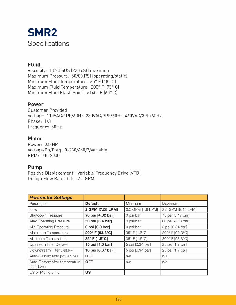
198
SMR2Specifi cations
FluidViscosity: 1,020 SUS (220 cSt) maximumMaximum Pressure: 50/80 PSI (operating/static)Minimum Fluid Temperature: 65° F (18° C)Maximum Fluid Temperature: 200° F (93° C)Minimum Fluid Flash Point: >140° F (60° C)
PowerCustomer ProvidedVoltage: 110VAC/1Ph/60Hz, 230VAC/3Ph/60Hz, 460VAC/3Ph/60HzPhase: 1/3Frequency 60Hz
MotorPower: 0.5 HPVoltage/Ph/Freq: 0-230/460/3/variableRPM: 0 to 2000
PumpPositive Displacement - Variable Frequency Drive (VFD)Design Flow Rate: 0.5 - 2.5 GPM
Parameter SettingsParameter Default Minimum Maximum
Flow 2 GPM [7.58 LPM] 0.5 GPM [1.9 LPM] 2.5 GPM [9.45 LPM]
Shutdown Pressure 70 psi [4.82 bar] 0 psi/bar 75 psi [5.17 bar]
Max Operating Pressure 50 psi [3.4 bar] 0 psi/bar 60 psi [4.13 bar]
Min Operating Pressure 0 psi [0.0 bar] 0 psi/bar 5 psi [0.34 bar]
Maximum Temperature 200° F [93.3°C] 35° F [1.6°C] 200° F [93.3°C]
Minimum Temperature 35° F [1.5°C] 35° F [1.6°C] 200° F [93.3°C]
Upstream Filter Delta-P 15 psi [1.0 bar] 5 psi [0.34 bar] 25 psi [1.7 bar]
Downstream Filter Delta-P 10 psi [0.67 bar] 5 psi [0.34 bar] 25 psi [1.7 bar]
Auto-Restart after power loss OFF n/a n/a
Auto-Restart after temperature
shutdown
OFF n/a n/a
US or Metric units US

199
SMR2Parts List
Quantity Parker Part # Description
1 165-00002 Drive, AC, A/B .5 HP 240V 1 PH
165-00001 Drive, AC, A/B .5 HP 480V 3 PH
165-00011 Drive, Line Filter, .5 HP 120V & 240V 1 PH
165-00014 Drive, Line Filter, .5 HP 460V 3 PH
1 270-00006 PLC/HMI
1 275-00007 Power Supply, H.V.
1 275-00002 Power Supply, A/B 24V 110-240V
1 275-00006 Power Supply, C/H 24V 380-480V
1 290-00001 Relay, H.V., A/B
1 245-00006 Light Module, A/B, Green
1 245-00005 Light Module, A/B, Yellow
1 250-00005 Motor, .5 HP, 230-380 STD
1 280-00014 Pump/Bypass, 2 GPM, STD
1 255-00016 O-Ring, vessel 1, 2 or 3
1 936623Q 5 Micron Filter, Upstream
1 936622Q 2 Micron Filter, Downstream
1 195-00003 Feedthru, H.V.
4 350-00001 Transducer, pressure
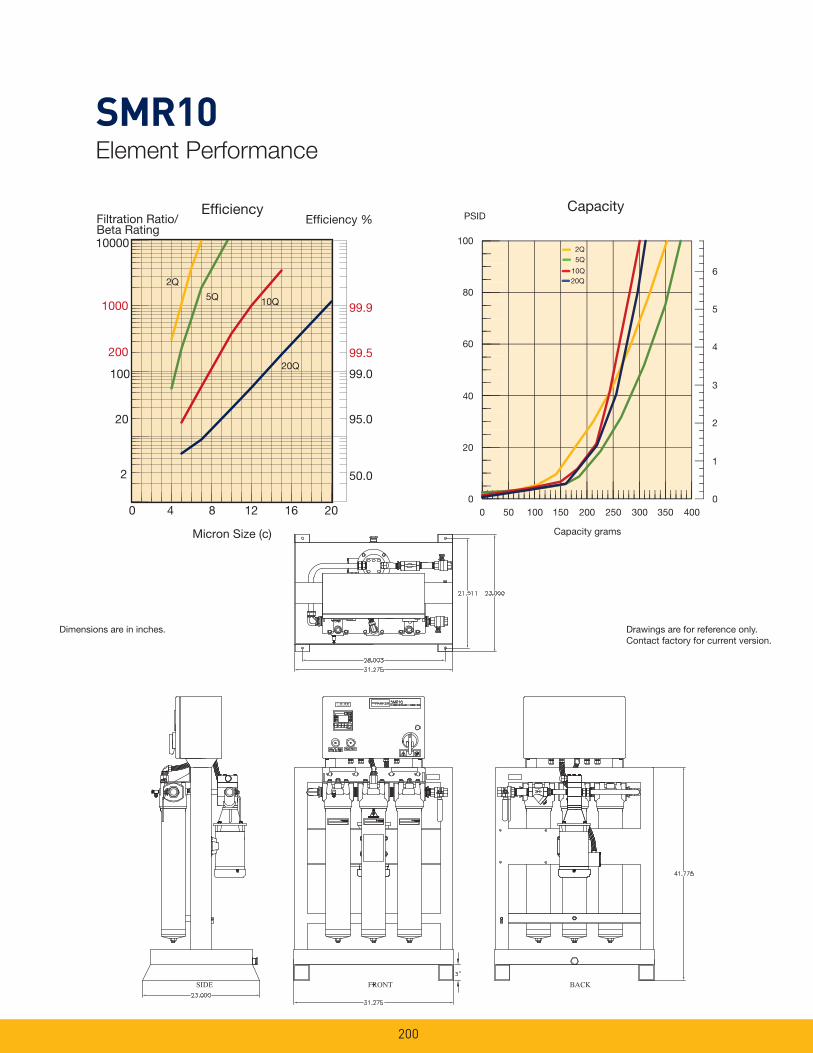
200
SMR10Element Performance
EfficiencyFiltration Ratio/Beta Rating
1000
10000
99.9
99.5
99.0100
200
20
2 50.0
95.0
5Q 10Q
20Q
2Q
0 4 8 12 16 20
Micron Size (c)
Efficiency %
0
1
2
3
4
5
6
0 50 100 150 200 250 300 350 400
Capacity grams
0
20
40
60
80
100
PSIDCapacity
20Q10Q
2Q5Q
Drawings are for reference only. Contact factory for current version.
Dimensions are in inches.
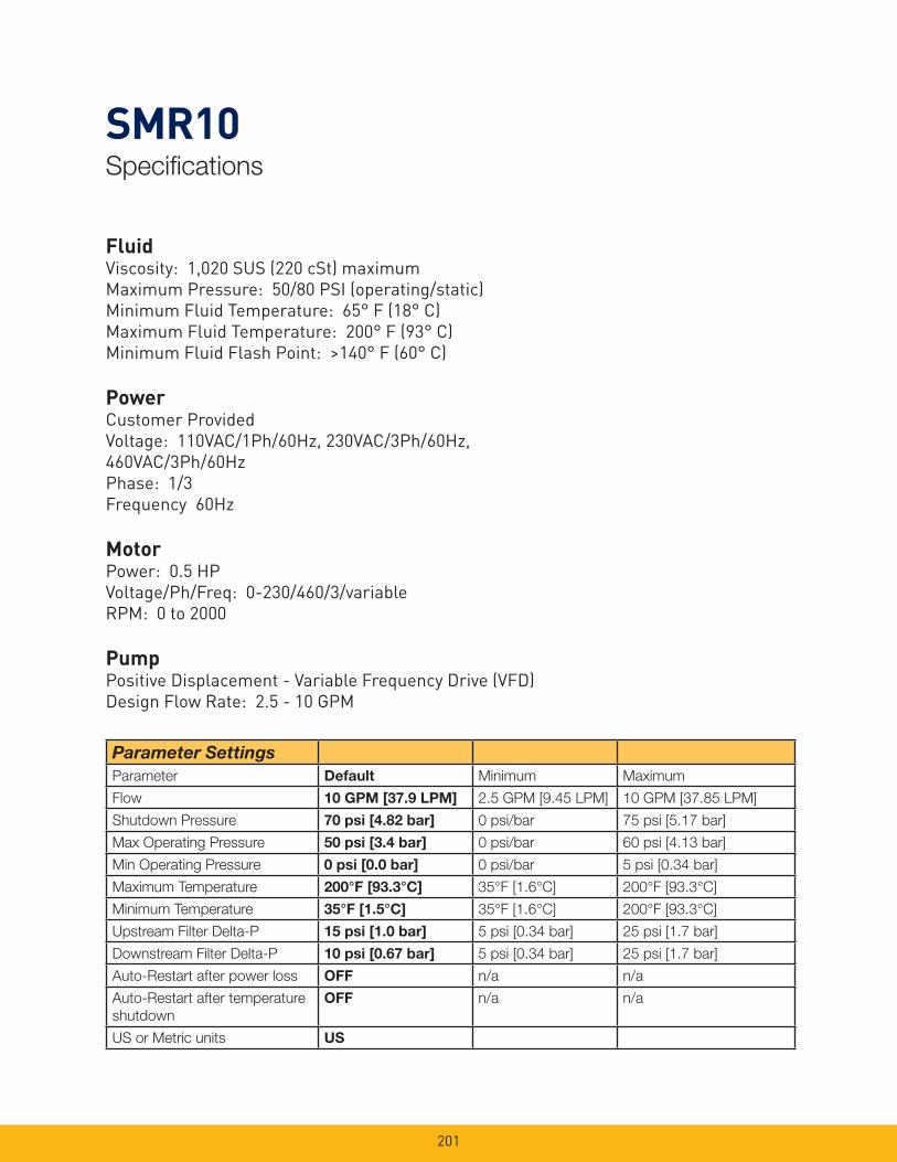
201
SMR10Specifi cations
Parameter SettingsParameter Default Minimum Maximum
Flow 10 GPM [37.9 LPM] 2.5 GPM [9.45 LPM] 10 GPM [37.85 LPM]
Shutdown Pressure 70 psi [4.82 bar] 0 psi/bar 75 psi [5.17 bar]
Max Operating Pressure 50 psi [3.4 bar] 0 psi/bar 60 psi [4.13 bar]
Min Operating Pressure 0 psi [0.0 bar] 0 psi/bar 5 psi [0.34 bar]
Maximum Temperature 200°F [93.3°C] 35°F [1.6°C] 200°F [93.3°C]
Minimum Temperature 35°F [1.5°C] 35°F [1.6°C] 200°F [93.3°C]
Upstream Filter Delta-P 15 psi [1.0 bar] 5 psi [0.34 bar] 25 psi [1.7 bar]
Downstream Filter Delta-P 10 psi [0.67 bar] 5 psi [0.34 bar] 25 psi [1.7 bar]
Auto-Restart after power loss OFF n/a n/a
Auto-Restart after temperature
shutdown
OFF n/a n/a
US or Metric units US
FluidViscosity: 1,020 SUS (220 cSt) maximumMaximum Pressure: 50/80 PSI (operating/static)Minimum Fluid Temperature: 65° F (18° C)Maximum Fluid Temperature: 200° F (93° C)Minimum Fluid Flash Point: >140° F (60° C)
PowerCustomer ProvidedVoltage: 110VAC/1Ph/60Hz, 230VAC/3Ph/60Hz, 460VAC/3Ph/60HzPhase: 1/3Frequency 60Hz
MotorPower: 0.5 HPVoltage/Ph/Freq: 0-230/460/3/variableRPM: 0 to 2000
PumpPositive Displacement - Variable Frequency Drive (VFD)Design Flow Rate: 2.5 - 10 GPM
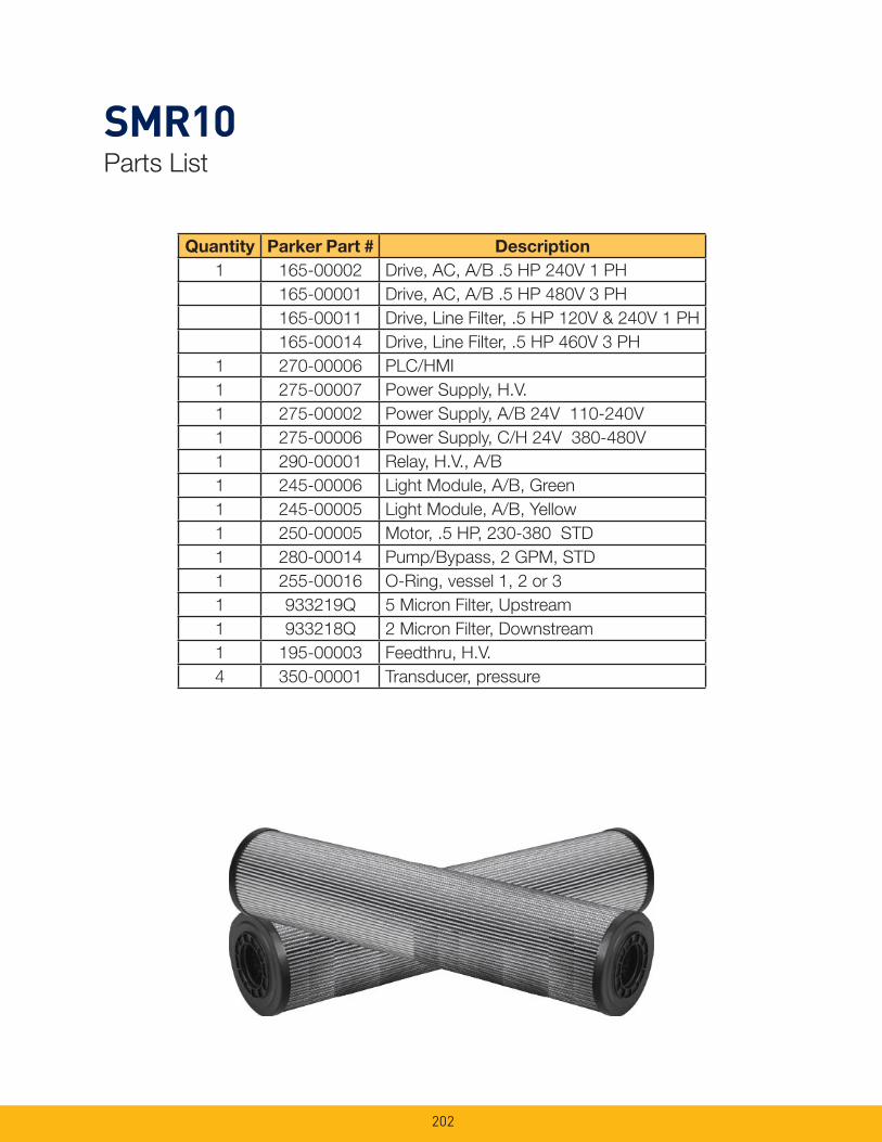
202
SMR10Parts List
Quantity Parker Part # Description
1 165-00002 Drive, AC, A/B .5 HP 240V 1 PH
165-00001 Drive, AC, A/B .5 HP 480V 3 PH
165-00011 Drive, Line Filter, .5 HP 120V & 240V 1 PH
165-00014 Drive, Line Filter, .5 HP 460V 3 PH
1 270-00006 PLC/HMI
1 275-00007 Power Supply, H.V.
1 275-00002 Power Supply, A/B 24V 110-240V
1 275-00006 Power Supply, C/H 24V 380-480V
1 290-00001 Relay, H.V., A/B
1 245-00006 Light Module, A/B, Green
1 245-00005 Light Module, A/B, Yellow
1 250-00005 Motor, .5 HP, 230-380 STD
1 280-00014 Pump/Bypass, 2 GPM, STD
1 255-00016 O-Ring, vessel 1, 2 or 3
1 933219Q 5 Micron Filter, Upstream
1 933218Q 2 Micron Filter, Downstream
1 195-00003 Feedthru, H.V.
4 350-00001 Transducer, pressure
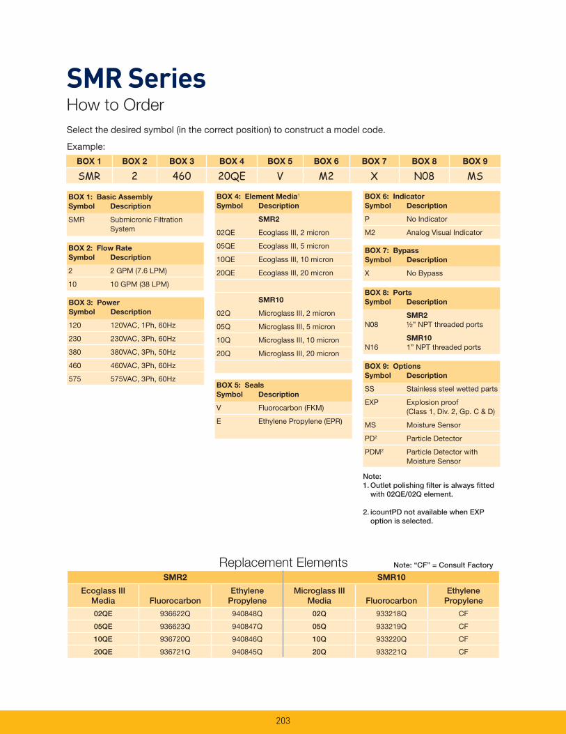
203
SMR2 SMR10
Ecoglass III Media Fluorocarbon
Ethylene Propylene
Microglass III Media Fluorocarbon
Ethylene Propylene
02QE 936622Q 940848Q 02Q 933218Q CF
05QE 936623Q 940847Q 05Q 933219Q CF
10QE 936720Q 940846Q 10Q 933220Q CF
20QE 936721Q 940845Q 20Q 933221Q CF
Replacement Elements
Example:
Select the desired symbol (in the correct position) to construct a model code.
Note: “CF” = Consult Factory
Note:1. Outlet polishing fi lter is always fi tted with 02QE/02Q element.
2. icountPD not available when EXP option is selected.
BOX 1 BOX 2 BOX 3 BOX 4 BOX 5 BOX 6 BOX 7 BOX 8 BOX 9
SMR 2 460 20QE V M2 X N08 MS
BOX 2: Flow Rate
Symbol Description
2 2 GPM (7.6 LPM)
10 10 GPM (38 LPM)BOX 8: Ports
Symbol Description
SMR2
N08 ½” NPT threaded ports
SMR10
N16 1” NPT threaded ports
BOX 1: Basic Assembly
Symbol Description
SMR Submicronic Filtration System
BOX 4: Element Media1
Symbol Description
SMR2
02QE Ecoglass III, 2 micron
05QE Ecoglass III, 5 micron
10QE Ecoglass III, 10 micron
20QE Ecoglass III, 20 micron
SMR10
02Q Microglass III, 2 micron
05Q Microglass III, 5 micron
10Q Microglass III, 10 micron
20Q Microglass III, 20 micron
BOX 6: Indicator
Symbol Description
P No Indicator
M2 Analog Visual Indicator
BOX 5: Seals
Symbol Description
V Fluorocarbon (FKM)
E Ethylene Propylene (EPR)
BOX 9: Options
Symbol Description
SS Stainless steel wetted parts
EXP Explosion proof (Class 1, Div. 2, Gp. C & D)
MS Moisture Sensor
PD2 Particle Detector
PDM2 Particle Detector with Moisture Sensor
BOX 7: Bypass
Symbol Description
X No Bypass
BOX 3: Power
Symbol Description
120 120VAC, 1Ph, 60Hz
230 230VAC, 3Ph, 60Hz
380 380VAC, 3Ph, 50Hz
460 460VAC, 3Ph, 60Hz
575 575VAC, 3Ph, 60Hz
SMR SeriesHow to Order

Notes
204
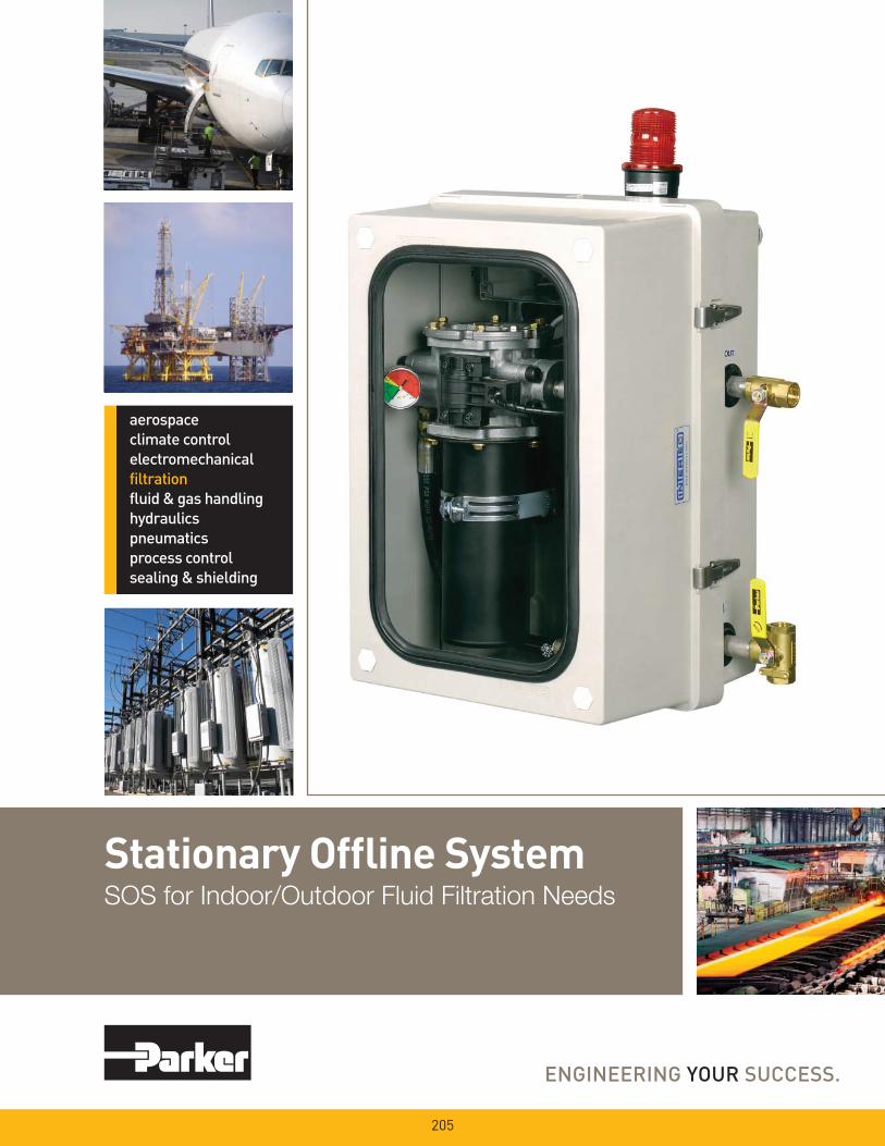
Stationary Offl ine SystemSOS for Indoor/Outdoor Fluid Filtration Needs
205
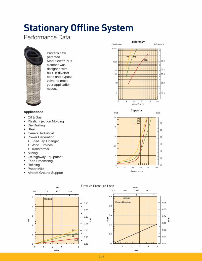
206
Parker’s new patented Modufl ow™ Plus element was designed with built-in diverter cone and bypass valve, to meet your application needs.
Applications
• Oil & Gas• Plastic Injection Molding• Die Casting• Steel• General Industrial• Power Generation • Load Tap Changer • Wind Turbines • Transformer• Mining• Off-highway Equipment• Food Processing• Refi ning• Paper Mills• Aircraft Ground Support
Stationary Offl ine SystemPerformance Data
2Q
5Q
150SUS
10Q
0.0 5.0 10.0 15.0
LPM
0
1
2
3
4
5
PS
ID
0 1 2 3 4 5
GPM
0.00
0.05
0.10
0.15
0.20
BA
R
0.25
0.30
0.0
0.2
0.4
0.6
0.8
1.0
PS
ID
0.0 5.0 10.0 15.0
LPM
0 1 2 3 4 5
GPM
0.00
0.01
0.02
0.03
0.04
BA
R
0.05
0.06Empty Housing
150SUS
% ycneiciffEEfficiency
Beta Rating
1000
10000
99.9
99.5
100
200
20
0.052
95.0
99.0
2Q 5Q
10Q
0 4 8 12 16 20Micron Size (c)
RABPSID
0
10
20
30
40
50
0.0
0.5
1.0
1.5
2.0
2.5
3.0
0 20 40 60 80 100
Capacity grams
2Q5Q
10Q
Capacity
Flow vs Pressure Loss
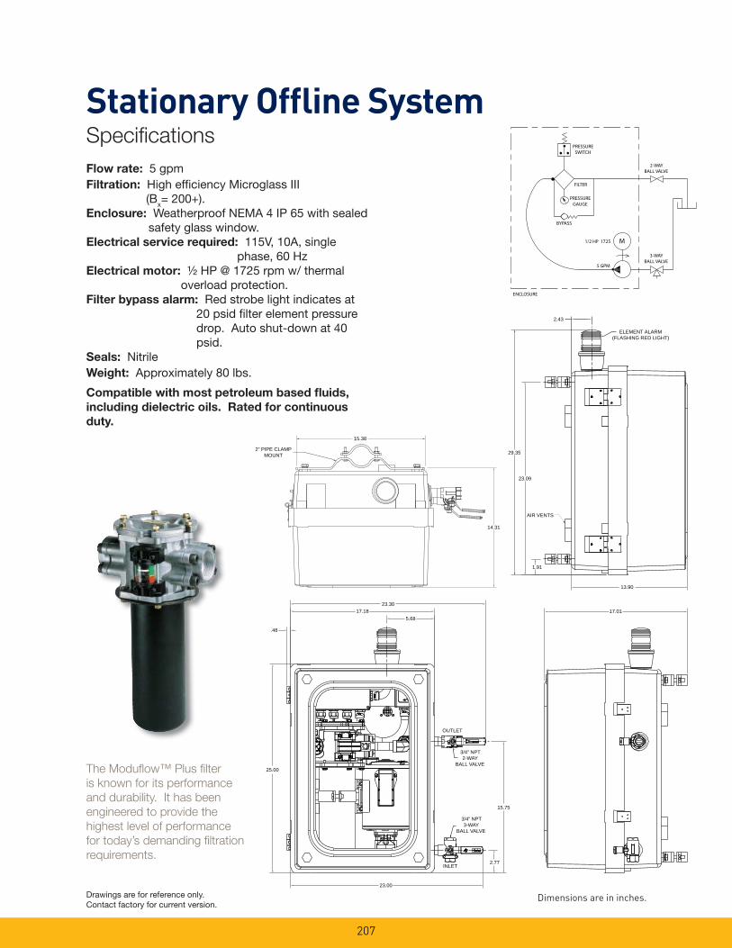
207
The Modufl ow™ Plus fi lter
is known for its performance
and durability. It has been
engineered to provide the
highest level of performance
for today’s demanding fi ltration
requirements.
23.3017.18
5.68
.48
25.00
23.00
2.77INLET
3/4” NPT3-WAY
BALL VALVE
15.75
3/4” NPT2-WAY
BALL VALVE
OUTLET
17.01
2“ PIPE CLAMPMOUNT
15.38
14.31
Flow rate: 5 gpmFiltration: High effi ciency Microglass III (Bx= 200+).Enclosure: Weatherproof NEMA 4 IP 65 with sealed
safety glass window.Electrical service required: 115V, 10A, single
phase, 60 HzElectrical motor: ½ HP @ 1725 rpm w/ thermal
overload protection.Filter bypass alarm: Red strobe light indicates at
20 psid fi lter element pressure drop. Auto shut-down at 40 psid.
Seals: NitrileWeight: Approximately 80 lbs.
Compatible with most petroleum based fl uids,
including dielectric oils. Rated for continuous
duty.
2.43
ELEMENT ALARM(FLASHING RED LIGHT)
29.35
23.09
AIR VENTS
1.91
13.90
Dimensions are in inches.Drawings are for reference only. Contact factory for current version.
Stationary Offl ine SystemSpecifi cations
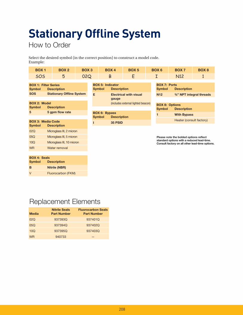
208
Select the desired symbol (in the correct position) to construct a model code. Example:
BOX 1 BOX 2 BOX 3 BOX 4 BOX 5 BOX 6 BOX 7 BOX 8
SOS 5 02Q B E I N12 1
BOX 1: Filter Series
Symbol Description
SOS Stationary Offl ine System
BOX 5: Indicator
Symbol Description
E Electrical with visual
gauge
(includes external lighted beacon)
BOX 4: Seals
Symbol Description
B Nitrile (NBR)
V Fluorocarbon (FKM)
BOX 8: Options
Symbol Description
1 With Bypass
Heater (consult factory)
Please note the bolded options refl ect
standard options with a reduced lead-time.
Consult factory on all other lead-time options.
BOX 2: Model
Symbol Description
5 5 gpm fl ow rate BOX 6: Bypass
Symbol Description
I 35 PSID
BOX 7: Ports
Symbol Description
N12 ¾” NPT integral threads
Stationary Offl ine SystemHow to Order
Replacement Elements Nitrile Seals Fluorocarbon Seals
Media Part Number Part Number
02Q 937393Q 937401Q
05Q 937394Q 937402Q
10Q 937395Q 937403Q
WR 940733 —
BOX 3: Media Code
Symbol Description
02Q Microglass III, 2 micron
05Q Microglass III, 5 micron
10Q Microglass III, 10 micron
WR Water removal
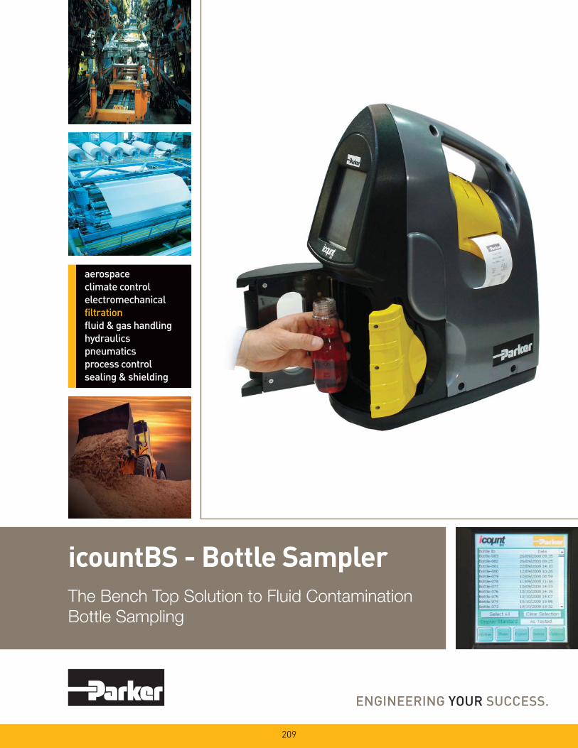
icountBS - Bottle SamplerThe Bench Top Solution to Fluid Contamination
Bottle Sampling
209

The Complete Solution - Industrial Design Combined with State of the Art Technology
210
The icountBS - Bottle Sampler
from Parker, with its innovative
industrial design, has been
developed for customers
looking for state of the art
technology, attention to detail
and the compactness of a
permanent laboratory particle
analysis instrument.
Combine this with on-board, laser based, leading edge technology to bring to all industries a truly revolutionary Particle Counter. The innovative icountBS is a product from the next generation of Parker’s fl uid particle analysis and monitoring solutions.
The IBS features an easy to use interactive touch screen, environmentally controlled pressurized bottle chamber, an internal compressor pump, automated door locking mechanism, sample tube cleaning sleeve that minimizes cross contamination, and an internal printer.The icountBS benefi ts from Parkers knowledge and experience of providing fl uid analysis equipment to the market for over 15 years.
icountBS - Bottle Sampler Features & Benefi ts• Customer programmable number of sample runs/sample bottle averaging and pre-test fl ush volumes from 10ml min. to 100ml max.
• Input via fl uid resistant touch screen display.
• Repeatable and reproducible performance to ISO4406:1999 and NAS1638 particle count distributions. For other calibration standards consult Parker Hydraulic Filter Division.
• On-board compressor and ‘shop’ air capable.
• Design concept allowing for portability. DC and rechargeable battery pack options built in.
• Sample tube self cleaning sleeve minimizing cross contamination.
• 500 test sample memory.
• Data download via USB jump drive included.
• Internal printer.

Home Screen Sample ID Input Number of Sample Runs
Sample Volume Flush Volume Start Test
211

212
Analyzing the Test ResultsOnce the automatic oil sample
test has been completed, what
next?
Solid contaminants in fl uid power systems vary in size, shape, form and quantity. The most harmful contaminants are normally between 6 microns and 14 microns. The ISO code is the preferred method of reporting quantity of contaminants.
The ISO code number corresponds to contamination levels relating to three sizes.
The fi rst scale number represents the number of particles that are equal to and greater than 4μm (c) per 100 milliliters of fl uid, the second number for particles that are equal to and greater than 6 μm(c) per 100 milliliters of fl uid and the third number for particles that are equal to and greater than 14 μm(c) per 100 milliliters of fl uid.
For example: An ISO code 20/18/14 indicates that there are between 500,000 and 1,000,000 particles that are equal to and
greater than 4μm(c), between 130,000 and 250,000 particles that are equal to and greater than 6μm(c), and between 8,000 and 16,000 particles that are equal to and greater than 14μm(c).
Component Cleanliness GuideSuggested acceptable contamination levels for various hydraulic systems
Target
Contamination
Class to
ISO 4406: 1999
Suggested Maximum
Particle LevelSensitivity Type of System Typical Components
4 μm(c) 6 μm(c) 14 μm(c) 4 μm(c) 6 μm(c) 14 μm(c)
15 13 9 16,000 4,000 250Supercritical
Silt-sensitive control systems with very high reliability. Laboratory or
aerospace
High performance servo valves
17 15 11 64,000 16,000 1,000 Critical
High performance servo and high pressure long
life systems, e.g. aircraft, machine tools, etc.
Industrial servo valves
18 16 13 130,000 32,000 4,000Very
Important
High quality reliablesystems. General machine
requirements
Piston pumps, proportional valves, compensated fl ow
controls
20 18 14 500,000 130,000 8,000 Important
General machinery and mobile systems. Medium
pressure, mediumcapacity
Vane pumps, spool valves
21 19 15 1,000,000 250,000 16,000 Average
Low pressure heavyindustrial systems,
or applications where long life is not critical
Gear pumps, manual andpoppet valves, cylinders
23 21 17 4,000,000 1,000,000 64,000Main
protectionLow pressure systems with large clearances
Ram pumps
Notes:
Tables have been generated by organizations in various industries.Some of the tables are defi ned in cumulative counts, e.g. ‘>6μm’ and others are represented as differential counts e.g. ‘6-14μm’.All μm(c) refer to MTD distributions. All μm references will refer to ACFTD distributions.All standards are in counts per 100ml and provide easy methods for converting particle counts into limits that are simpleto interpret. By noting the requirements of the standard, particle counts can be accurately converted to contamination levels.
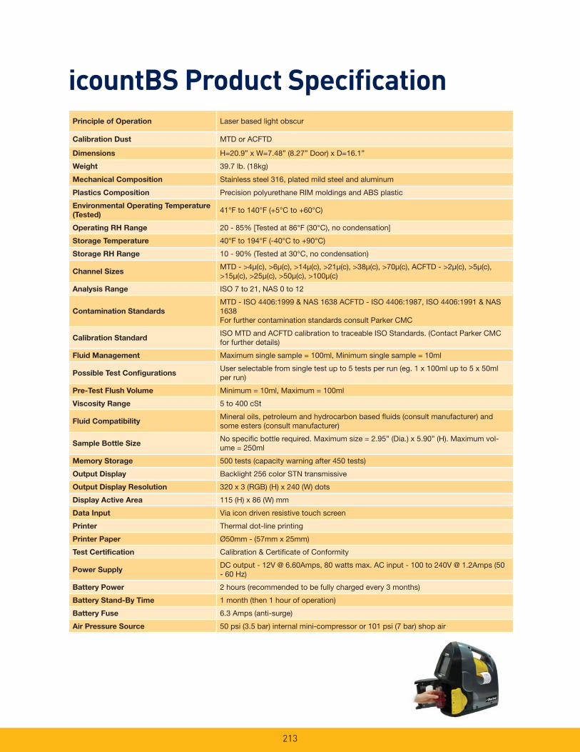
213
icountBS Product Specifi cationPrinciple of Operation Laser based light obscur
Calibration Dust MTD or ACFTD
Dimensions H=20.9” x W=7.48” (8.27” Door) x D=16.1”
Weight 39.7 lb. (18kg)
Mechanical Composition Stainless steel 316, plated mild steel and aluminum
Plastics Composition Precision polyurethane RIM moldings and ABS plastic
Environmental Operating Temperature
(Tested)41°F to 140°F (+5°C to +60°C)
Operating RH Range 20 - 85% [Tested at 86°F (30°C), no condensation]
Storage Temperature 40°F to 194°F (-40°C to +90°C)
Storage RH Range 10 - 90% (Tested at 30°C, no condensation)
Channel SizesMTD - >4μ(c), >6μ(c), >14μ(c), >21μ(c), >38μ(c), >70μ(c), ACFTD - >2μ(c), >5μ(c), >15μ(c), >25μ(c), >50μ(c), >100μ(c)
Analysis Range ISO 7 to 21, NAS 0 to 12
Contamination Standards
MTD - ISO 4406:1999 & NAS 1638 ACFTD - ISO 4406:1987, ISO 4406:1991 & NAS 1638For further contamination standards consult Parker CMC
Calibration StandardISO MTD and ACFTD calibration to traceable ISO Standards. (Contact Parker CMC for further details)
Fluid Management Maximum single sample = 100ml, Minimum single sample = 10ml
Possible Test Confi gurationsUser selectable from single test up to 5 tests per run (eg. 1 x 100ml up to 5 x 50ml per run)
Pre-Test Flush Volume Minimum = 10ml, Maximum = 100ml
Viscosity Range 5 to 400 cSt
Fluid CompatibilityMineral oils, petroleum and hydrocarbon based fl uids (consult manufacturer) and some esters (consult manufacturer)
Sample Bottle SizeNo specifi c bottle required. Maximum size = 2.95” (Dia.) x 5.90” (H). Maximum vol-ume = 250ml
Memory Storage 500 tests (capacity warning after 450 tests)
Output Display Backlight 256 color STN transmissive
Output Display Resolution 320 x 3 (RGB) (H) x 240 (W) dots
Display Active Area 115 (H) x 86 (W) mm
Data Input Via icon driven resistive touch screen
Printer Thermal dot-line printing
Printer Paper Ø50mm - (57mm x 25mm)
Test Certifi cation Calibration & Certifi cate of Conformity
Power SupplyDC output - 12V @ 6.60Amps, 80 watts max. AC input - 100 to 240V @ 1.2Amps (50 - 60 Hz)
Battery Power 2 hours (recommended to be fully charged every 3 months)
Battery Stand-By Time 1 month (then 1 hour of operation)
Battery Fuse 6.3 Amps (anti-surge)
Air Pressure Source 50 psi (3.5 bar) internal mini-compressor or 101 psi (7 bar) shop air
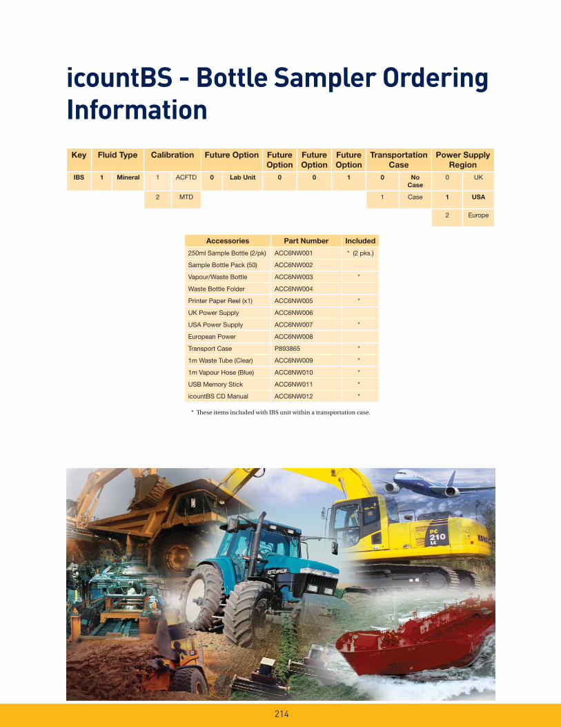
214
icountBS - Bottle Sampler Ordering Information
Key Fluid Type Calibration Future Option Future
Option
Future
Option
Future
Option
Transportation
Case
Power Supply
Region
IBS 1 Mineral 1 ACFTD 0 Lab Unit 0 0 1 0 No
Case
0 UK
2 MTD 1 Case 1 USA
2 Europe
Accessories Part Number Included
250ml Sample Bottle (2/pk) ACC6NW001 * (2 pks.)
Sample Bottle Pack (50) ACC6NW002
Vapour/Waste Bottle ACC6NW003 *
Waste Bottle Folder ACC6NW004
Printer Paper Reel (x1) ACC6NW005 *
UK Power Supply ACC6NW006
USA Power Supply ACC6NW007 *
European Power ACC6NW008
Transport Case P893865 *
1m Waste Tube (Clear) ACC6NW009 *
1m Vapour Hose (Blue) ACC6NW010 *
USB Memory Stick ACC6NW011 *
icountBS CD Manual ACC6NW012 *
* Th ese items included with IBS unit within a transportation case.

icountPDOnline Particle Detector
215

216
icountPDThe icountPD from Parker represents the most up-to-date technology in solid particle detection.
The design dynamics, attention to detail, and small size of the permanently mounted, on-line particle detector brings a truly innovative product to all industry. The laser based, leading-edge technology is a cost effective market solution to fluid management and contamination control.
Mobile Equipment
• Earth Moving Machinery
• Harvesting
• Forestry
• Agriculture
Industrial Equipment
• Production Plants
• Fluid Transfers
• Pulp & Paper
• Refineries
Features and benefits of the icountPD include:
• Independent monitoring of system contamination trends.
• Early warning LED or digital display indicators for Low, Medium and High contamination levels.
• Moisture % RH LED indicator (optional).
• Cost effective solution in prolonging fluid life and reducing machine downtime.
• Visual indicators with power and alarm output warnings.
• Continuous performance for dependable analysis.
• Hydraulic, phosphate ester & fuel fluid compatible construction.
• Self diagnostic software.
• Fully integrated PC/PLC integration technology such as:
RS232 and 0-5 Volt, 4-20mA, and CANBUS J1939.
Typical ApplicationsPower Generation
• Wind Turbines
• Gearboxes
• Lubrication Systems
Maintenance
• Test Rigs
• Flushing Stands
Standard icountPD is designed for test stand, fl ushing skids, fi lter carts and other industrial applications.
icountPDR is designed for mobile equipment or any outside use other than hazardous environment.
icountPDZ is intended for applications that require a zone 2 safety such as off-shore platforms or any other hazardous environment.
For Zone 1 applications the standard icountPD can be used within a NEMA7 enclosure.
3 Versions Available

217
icountPDFeatures and Benefi ts
Diagnostic self check start-up time 5 seconds
Measurement period 5 to 180 seconds
Reporting interval through RS232 0 to 3600 seconds
Digital LED display update time Every second
Limit relay output Changes occur +/- 1 ISO code at set limit (Hysteresis ON)
or customer set (Hysteresis OFF)
4-20mA output signal Continuous
Principle of operation Laser diode optical detection of actual particulates
Reporting codes ISO 7 – 21, NAS 0 – 12, (AS 00 – 12 contact Parker)
Icount will also report less than ISO 7, subject to the statistical uncertainty
defi ned in ISO4406:1999, which is shown in the RS232, reporting results
as appropriate e.g “>6”
Calibration By recognized on-line methods, confi rmed by the relevant International
Standards Organization procedures
Calibration recommendation 12 months
Performance +/- 1 ISO Code (dependant on stability of fl ow)
Reproducibility / Repeatability Better than 1 ISO Code
Power requirement Regulated 9 to 40Vdc
Maximum current draw 150mA
Hydraulic connection M16 x 2 hydraulic test points (5/8” BSF for aggressive version)
Flow range through the device 40 to 140 ml/min (optimum fl ow = 60ml/min)
Online fl ow range via System 20 Size 0 = 6 to 25 l/min - (optimum fl ow = 15 l/min)
Inline Sensors Size 1 = 24 to 100 l/min - (optimum fl ow = 70 l/min)
Size 2 = 170 to 380 l/min - (optimum fl ow = 250 l/min)
Required differential pressure
across Inline Sensors 5.8 psi (0.4 bar) minimum
Viscosity range 10 to 500 cSt
Temperature Operating environment: -4°F to +140°F (-20°C to +60°C)
Storage: -40°F to +176°F (-40°C to +80°C)
Operating fl uid: +32°F to +185°F (0°C to +85°C)
Working pressure 30 to 6,000 PSI (2 to 420 bar)
Moisture sensor calibration ±5% RH (over compensated temperature range of +10°C to +80°C)
Operating humidity range 5% RH to 100% RH
Moisture sensor stability ±0.2% RH typical at 50% RH in one year
Certifi cation IP66 rated
EMC/RFI – EN61000-6-2:2001
EN61000-6-3:2001
Materials User friendly construction
Stainless Steel hydraulic block
Viton seals
Dimensions 7.2” x 6.1” x 3.4” (182mm x 155mm x 86mm)
Weight 2.9 lbs. (1.3 kg)
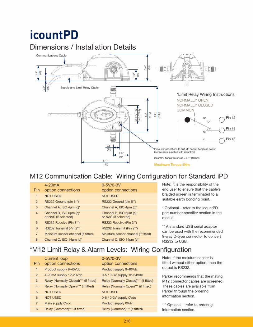
218
icountPDDimensions / Installation Details
1.9”
(49)
0.6”
(16)
1.5”
(37)
3.4”
(86)
2.4”
CTR
S
(60
CTR
S)
4.3”
(110
)
7.2”
(182
)6.1”
(155)
2.0”
(52)
0.8”
(21) 2 mounting locations to suit M5 socket head cap screw.(Screw pack supplied with icountPD)
icountPD fl ange thickness = 0.4” (10mm)
Maximum Torque 5Nm
M12 Communication Cable: Wiring Confi guration for Standard iPD
Pin4-20mA option connections
0-5V/0-3V option connections
1 NOT USED NOT USED
2 RS232 Ground (pin 5**) RS232 Ground (pin 5**)
3 Channel A, ISO 4μm (c)* Channel A, ISO 4μm (c)*
4 Channel B, ISO 6μm (c)* or NAS (if selected)
Channel B, ISO 6μm (c)* or NAS (if selected)
5 RS232 Receive (Pin 3**) RS232 Receive (Pin 3**)
6 RS232 Transmit (Pin 2**) RS232 Transmit (Pin 2**)
7 Moisture sensor channel (if fi tted) Moisture sensor channel (if fi tted)
8 Channel C, ISO 14μm (c)* Channel C, ISO 14μm (c)*
Note: It is the responsibility of the end user to ensure that the cable’s braided screen is terminated to a suitable earth bonding point.
* Optional – refer to the icountPD part number specifier section in the manual.
** A standard USB serial adaptor can be used with the recommended 9-way D-type connector to convert RS232 to USB.
*M12 Limit Relay & Alarm Levels: Wiring Confi guration
PinCurrent loop option connections
0-5V/0-3V option connections
1 Product supply 9-40Vdc Product supply 9-40Vdc
2 4-20mA supply 12-20Vdc 0-5 / 0-3V supply 12-24Vdc
3 Relay (Normally Closed)*** (if fi tted) Relay (Normally Closed)*** (if fi tted)
4 Relay (Normally Open)*** (if fi tted) Relay (Normally Open)*** (if fi tted)
5 NOT USED NOT USED
6 NOT USED 0-5 / 0-3V supply 0Vdc
7 Main supply 0Vdc Product supply 0Vdc
8 Relay (Common)*** (if fi tted) Relay (Common)*** (if fi tted)
Note: If the moisture sensor is fitted without either option, then the output is RS232.
Parker recommends that the mating M12 connector cables are screened. These cables are available from Parker through the ordering information section.
*** Optional – refer to ordering information section.
*Limit Relay Wiring InstructionsNORMALLY OPENNORMALLY CLOSEDCOMMON
Pin #2
Pin #3
Pin #8
Communications Cable
Supply and Limit Relay Cable

219
icountPDVariable mA Output Settings
The following table can be used to equate the analogue output to an ISO or NAS Code.
Example: ISO code 12 is equal to 10mA.
0.0
2.04.0
6.0
8.010.0
12.0
14.0
16.018.0
20.0
201918171615141312115 6 7 8 9 1043210 21
ISO CODE
Mill
iam
p O
utp
ut
0
24
6
810
12
14
1618
20
1312115 6 7 8 9 1043210
NAS CODE
Mill
iam
p O
utp
ut 4-20mA output settings
ISO SettingmA current = (ISO Code / 2) +4 eg. 10mA = (ISO 12 / 2) +4orISO Code = (mA current - 4) *2eg. ISO 12 = (10mA -4) *2
NAS SettingmA current = NAS Code +5eg. 15mA = NAS 10 +5orNAS Code = mA current -5eg. NAS 10 = 15mA – 5
mA ISO
4.0 0 4.5 1 5.0 2 5.5 3 6.0 4 6.5 5 7.0 6 7.5 7 8.0 8 8.5 9 9.0 10 9.5 11 10.0 12 10.5 13 11.0 14 11.5 15 12.0 16 12.5 17 13.0 18 13.5 19 14.0 20 14.5 21 15.0 ** 15.5 ** 16.0 ** 16.5 ** 17.0 ** 17.5 ** 18.0 ** 18.5 ** 19.0 OVERRANGE 19.5 OVERRANGE 20.0 ERROR
mA NAS
4 00 5 0 6 1 7 2 8 3 9 4 10 5 11 6 12 7 13 8 14 9 15 10 16 11 17 12 18 ** 19 ** 20 ERROR
Variable Voltage Output SettingsThe variable voltage output option has the capability of two different voltage ranges: a 0-5Vdc range as standard, and a user-selectable 0-3Vdc range.
The full list of commands on how to change the voltage output is available from Parker.
The following tables can be used to relate the analog output to an ISO or NAS code.
ISO Err 00 0 1 2 3 4 5 6 7 8 9 10 11 12 Err
0-5Vdc <0.4 0.6 0.9 1.2 1.5 1.8 2.1 2.4 2.7 3.0 3.3 3.6 3.9 4.2 4.5 >4.6
0-3Vdc <0.2 N.S. 0.3 0.5 0.7 0.9 1.1 1.3 1.5 1.7 1.9 2.1 2.3 2.5 2.7 >2.8
Table relating NAS codes to voltage output
ISO Err 0 1 2 3 4 5 6 7 8 9 10 11
0-5Vdc <0.2 0.3 0.5 0.7 0.9 1.1 1.3 1.5 1.7 1.9 2.1 2.3 2.5
0-3Vdc <0.15 0.2 0.3 0.4 0.5 0.6 0.7 0.8 0.9 1.0 1.1 1.2 1.3
ISO 12 13 14 15 16 17 18 19 20 21 22 Err
0-5Vdc 2.7 2.9 3.1 3.3 3.5 3.7 3.9 4.1 4.3 4.5 4.7 >4.8
0-3Vdc 1.4 1.5 1.6 1.7 1.8 1.9 2.0 2.1 2.2 2.3 2.4 >2.45
Table relating ISO codes to voltage output
For example, in a 0-5Vdc range, ISO code 16 is eaual to an output of 3.5Vdc. In a 0-3Vdc range, ISO code 8 is equal to an output of 1.0Vdc.

220
icountPDDigital display indication
The digital display will show the actual measured codes, the channel (μ) size and the user defineable limits. Visible display of the channel size and user definable limits will alternate.
The moisture sensor reading (%RH) will also be shown – if the moisture sensor option is fitted.
Saturation 4-20mA 0-3Vdc 0-5Vdc
5% 4.8 0.15 0.25
25% 8 0.75 1.25
50% 12 1.50 2.50
75% 16 2.25 3.75
100% 20 3.00 5.00
Channel sizes/limits
Automatic light sensor
MTD calibrated
Measured ISO codes
Moisture sensor reading
Display Parameters (ISO 4406/NAS 1638)
LED display indication
The LED display uses 3 sets of LED for the indication of ISO 4406 and NAS1638 code figures. Individual code lights will trigger based on the customer settings.
The order of trigger will be:
• Solid green = one ISO code, or better, below the set point (limit)
• Blinking green = ISO code at the set point (limit)
• Solid red = one ISO code above the set point (limit)
• Blinking red = two ISO codes, or more, above the set point (limit)
• Flashing digit(s) = code(s) that are above the set point (limit)
The display for ISO4406 and NAS1638 are identical. The ISO display is shown below.
The order of trigger for both of the codes and moisture sensor option is:
• Solid digit(s) = code(s) that are at or below the set point (limit)
Error detection
In the unlikely event of an error occurring, the digital display on the icountPD will simply display the actual error code only – i.e. ERROR 13 (a full list of error codes is detailed in the icountPD user manual).
Moisture sensor output
settings
The moisture sensor is an option that can be included when specifying the icountPD. The moisture sensor reports on the saturation levels of the fluid passing through the icountPD sensing cell. The output is a linear scale, reporting within the range of 5% saturation to 100% saturation.
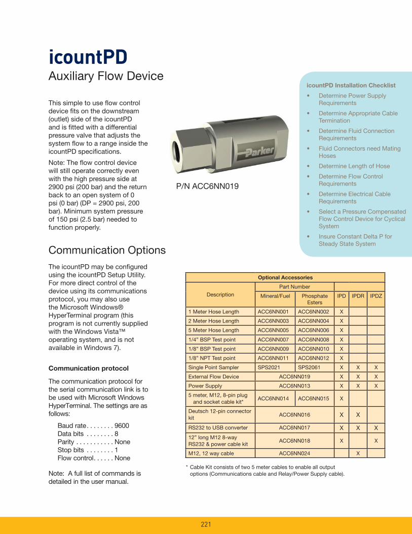
221
This simple to use fl ow control device fi ts on the downstream (outlet) side of the icountPD and is fi tted with a differential pressure valve that adjusts the system fl ow to a range inside the icountPD specifi cations.
Note: The fl ow control device will still operate correctly even with the high pressure side at 2900 psi (200 bar) and the return back to an open system of 0 psi (0 bar) (DP = 2900 psi, 200 bar). Minimum system pressure of 150 psi (2.5 bar) needed to function properly.
Auxiliary Flow DeviceicountPD
The icountPD may be confi gured using the icountPD Setup Utility. For more direct control of the device using its communications protocol, you may also use the Microsoft Windows® HyperTerminal program (this program is not currently supplied with the Windows Vista™ operating system, and is not available in Windows 7).
Communication Options
Communication protocol
The communication protocol for the serial communication link is to be used with Microsoft Windows HyperTerminal. The settings are as follows:
Baud rate . . . . . . . . 9600Data bits . . . . . . . . 8Parity . . . . . . . . . . . NoneStop bits . . . . . . . . 1Flow control . . . . . . None
Note: A full list of commands is detailed in the user manual.
P/N ACC6NN019
Optional Accessories
DescriptionPart Number
Mineral/Fuel Phosphate Esters
IPD IPDR IPDZ
1 Meter Hose Length ACC6NN001 ACC6NN002 X
2 Meter Hose Length ACC6NN003 ACC6NN004 X
5 Meter Hose Length ACC6NN005 ACC6NN006 X
1/4” BSP Test point ACC6NN007 ACC6NN008 X
1/8” BSP Test point ACC6NN009 ACC6NN010 X
1/8” NPT Test point ACC6NN011 ACC6NN012 X
Single Point Sampler SPS2021 SPS2061 X X X
External Flow Device ACC6NN019 X X X
Power Supply ACC6NN013 X X X
5 meter, M12, 8-pin plug and socket cable kit*
ACC6NN014 ACC6NN015 X
Deutsch 12-pin connector kit ACC6NN016 X X
RS232 to USB converter ACC6NN017 X X X
12” long M12 8-way RS232 & power cable kit
ACC6NN018 X X
M12, 12 way cable ACC6NN024 X
* Cable Kit consists of two 5 meter cables to enable all output options (Communications cable and Relay/Power Supply cable).
icountPD Installation Checklist
• Determine Power Supply Requirements
• Determine Appropriate Cable Termination
• Determine Fluid Connection Requirements
• Fluid Connectors need Mating Hoses
• Determine Length of Hose
• Determine Flow Control Requirements
• Determine Electrical Cable Requirements
• Select a Pressure Compensated Flow Control Device for Cyclical System
• Insure Constant Delta P for Steady State System
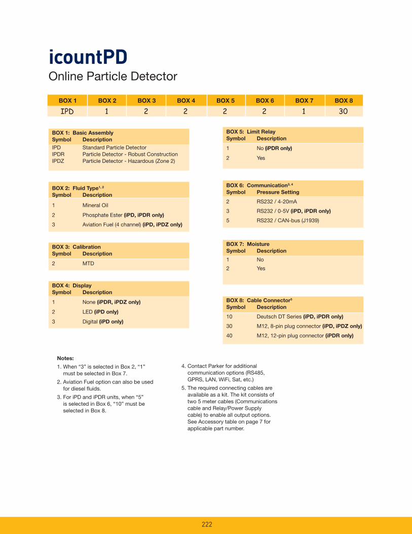
222
Notes:
1. When “3” is selected in Box 2, “1” must be selected in Box 7.
2. Aviation Fuel option can also be used for diesel fl uids.
3. For iPD and iPDR units, when “5” is selected in Box 6, “10” must be selected in Box 8.
BOX 1 BOX 2 BOX 3 BOX 4 BOX 5 BOX 6 BOX 7 BOX 8
IPD 1 2 2 2 2 1 30
BOX 1: Basic Assembly
Symbol Description
IPD Standard Particle DetectorIPDR Particle Detector - Robust ConstructionIPDZ Particle Detector - Hazardous (Zone 2)
BOX 5: Limit Relay
Symbol Description
1 No (iPDR only)
2 Yes
BOX 4: Display
Symbol Description
1 None (iPDR, iPDZ only)
2 LED (iPD only)
3 Digital (iPD only)
BOX 8: Cable Connector5
Symbol Description
10 Deutsch DT Series (iPD, iPDR only)
30 M12, 8-pin plug connector (iPD, iPDZ only)
40 M12, 12-pin plug connector (iPDR only)
BOX 2: Fluid Type1, 2
Symbol Description
1 Mineral Oil
2 Phosphate Ester (iPD, iPDR only)
3 Aviation Fuel (4 channel) (iPD, iPDZ only)
BOX 3: Calibration
Symbol Description
2 MTD
BOX 6: Communication3, 4
Symbol Pressure Setting
2 RS232 / 4-20mA
3 RS232 / 0-5V (iPD, iPDR only)
5 RS232 / CAN-bus (J1939)
BOX 7: Moisture
Symbol Description
1 No
2 Yes
icountPDOnline Particle Detector
4. Contact Parker for additional communication options (RS485, GPRS, LAN, WiFi, Sat, etc.)
5. The required connecting cables are available as a kit. The kit consists of two 5 meter cables (Communications cable and Relay/Power Supply cable) to enable all output options. See Accessory table on page 7 for applicable part number.

Par-Test™
Fluid Analysis
223
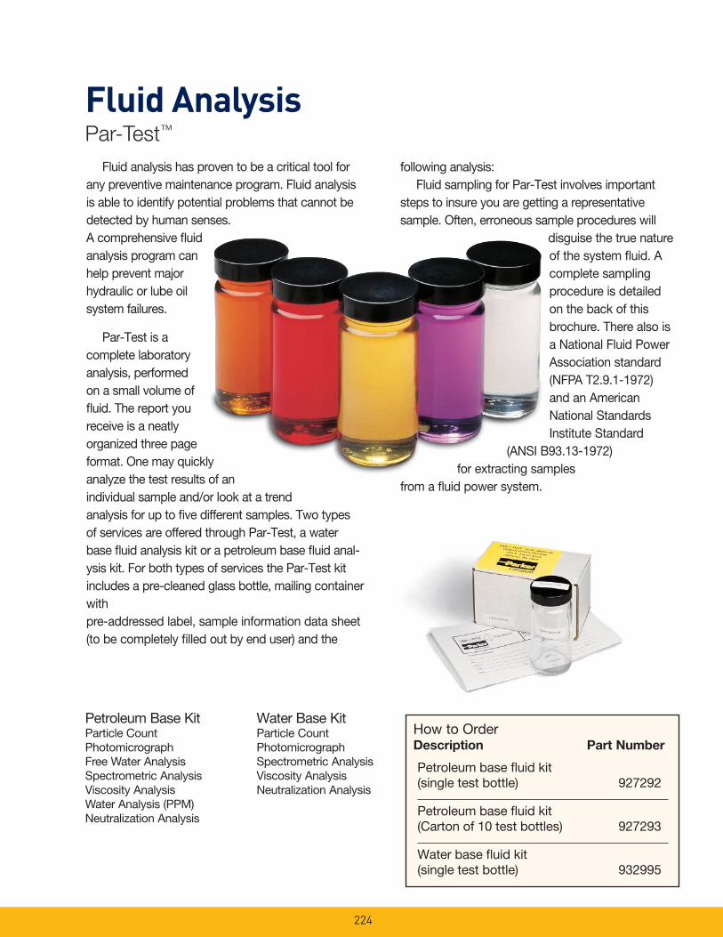
Fluid AnalysisPar-Test™
Water Base KitParticle CountPhotomicrographSpectrometric AnalysisViscosity AnalysisNeutralization Analysis
Petroleum Base KitParticle Count PhotomicrographFree Water AnalysisSpectrometric AnalysisViscosity AnalysisWater Analysis (PPM)Neutralization Analysis
Petroleum base fl uid kit (single test bottle) 927292
Petroleum base fl uid kit (Carton of 10 test bottles) 927293
Water base fl uid kit (single test bottle) 932995
How to OrderDescription Part Number
Fluid analysis has proven to be a critical tool for any preventive main te nance program. Fluid analysis is able to identify potential problems that cannot be de tect ed by human senses. A com pre hen sive fl uid analysis program can help pre vent major hydraulic or lube oil sys tem fail ures.
Par-Test is a complete lab o ra to ry analysis, performed on a small volume of fl uid. The report you receive is a neatly organized three page format. One may quickly analyze the test results of an individual sample and/or look at a trend anal y sis for up to fi ve different sam ples. Two types of ser vic es are of fered through Par-Test, a water base fl uid analysis kit or a pe tro leum base fl uid anal-y sis kit. For both types of services the Par-Test kit in cludes a pre-cleaned glass bottle, mail ing container with pre-ad dressed label, sample information data sheet (to be com plete ly fi lled out by end user) and the
fol low ing anal y sis: Fluid sampling for Par-Test involves im por tant steps to insure you are getting a rep re sen ta tive sample. Often, erroneous sample pro ce dures will
dis guise the true nature of the system fl uid. A complete sampling procedure is detailed on the back of this brochure. There also is a National Fluid Power Association standard (NFPA T2.9.1-1972) and an American National StandardsInstitute Standard
(ANSI B93.13-1972) for extracting samples
from a fl uid power system.
224
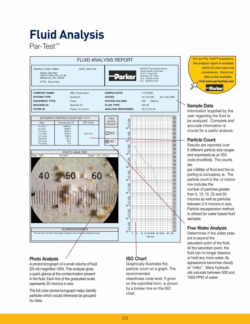
Fluid AnalysisPar-Test™
FLUID ANALYSIS REPORT
COM PA NY NAME: ABC Corporation
SYSTEM TYPE: Hydraulic
EQUIPMENT TYPE: Press
MACHINE ID: Machine #1
FILTER ID: Parker 10 micron
SAMPLE DATE: 7/12/2004
HOURS: (on oil) 948 (on unit) 2000
SYSTEM VOLUME: 200 Gallons
FLUID TYPE: AW 46
ANALYSIS PERFORMED: N2,S,T,V4,W
Size Counts per ml. ISO Code >4 μm(c) 35000.0 >6 μm(c) 15498.0 >10 μm(c) 6000.0 >14 μm(c) 2600.0 22/21/19 >21 μm(c) 1468.0 >38 μm(c) 754.0 >50 μm(c) 58.0 >70 μm(c) 3.0
PARTEST Flu id Anal y sis Ser vicePark er Hannifi n Cor po ra tion1016 E. Airport Rd.Stillwater, OK 74075Tele: (405)624-0400Fax: (405)624-0401
SAMPLE CODE: 93844 DATE: 09/01/04
Parker Hannifan 16810 Fulton Rd. Co #2 Metamora, OH, 43540
ATTN: Kevin Noe
*The red line in the ISO chart graph indicates recommended cleanliness level.
ALARMS/REMARKS
AUTOMATIC PARTICLE COUNT ISO 11171 FREEWATER
PRESENT
NO
PHOTO ANALYSIS Mag.: 160x Vol 20ml Scale: 1 div = 20 μm
���� ����
����������������
����������������
���������������
���������������
���������������
���������������
��������������
���������������
��������������
� � � � �� � � � �
�
�
�
�
�
�
�
�
�
�
�
�
�
�
�
�
��
�
��
��
��
��
��
��
X
ISO ChartGraphically illustrates the particle count on a graph. The rec om mend ed clean li ness code level, if given on the submittal form, is shown by a broken line on the ISO chart.
Sample DataIn for ma tion supplied by the user re gard ing the fl uid to be an a lyzed. Com plete and ac cu rate in for ma tion is crucial for a useful analysis.
Particle CountResults are reported over 6 different particle size ranges and expressed as an ISO code (modifi ed). The counts are per milliliter of fl uid and the re-porting is cumulative; ie. The particle count in the >2 micron row includes the number of particles greater than 5, 10, 15, 25 and 50 microns as well as particles between 2-5 microns in size. Particle resuspension method is utilized for water based fl uid samples.
Free Water AnalysisDetermines if the water pres-ent is be yond the sat u ra tion point of the fl uid. At the sat u ra tion point, the fl uid can no longer dis solve or hold any more water. Its appearance becomes cloudy or “milky”. Many hydraulic oils saturate between 500 and 1000 PPM of water.
Photo AnalysisA pho t o mi cro graph of a small volume of fl uid (20 ml) mag ni fi ed 100X. This analysis gives a quick glance at the con tam i na tion present in the fl uid. Each line of the grad u at ed scale represents 20 microns in size.
The full color pho t o mi cro graph helps identify particles which would otherwise be grouped by class.
YES
225
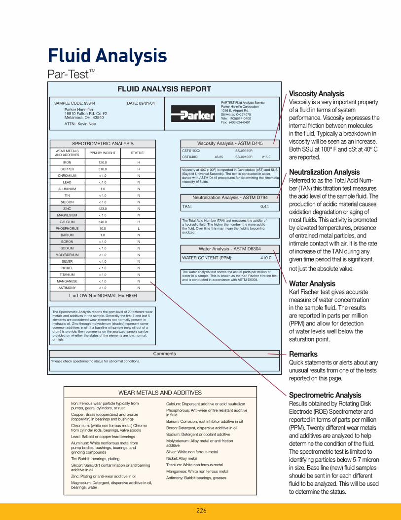
Fluid AnalysisPar-Test™
FLUID ANALYSIS REPORT
CST@100C: SSU@210F:
CST@40C: 46.25 SSU@100F: 215.0
WATER CONTENT (PPM): 410.0
TAN: 0.44
WEAR METALSAND AD DI TIVES
PPM BY WEIGHT STATUS*
The Spectometic Analysis reports the ppm level of 20 different wear metals and additives in the sample. Generally the fi rst 7 and last 5 elements are considered wear elements not normally present in hydraulic oil. Zinc through molybdenum (shaded) represent some common additives in oil. If a baseline oil sample (new oil out of a drum) is provide, then comments on the analyzed sample can be provided on whether the status of the elements are low, normal, or high.
SPECTROMETRIC ANALYSIS
L = LOW N = NOR MAL H= HIGH
Viscosity Analysis - ASTM D445
Water Analysis - ASTM D6304
Neutralization Analysis - ASTM D794
PARTEST Flu id Anal y sis Ser vicePark er Hannifi n Cor po ra tion1016 E. Airport Rd.Stillwater, OK 74075Tele: (405)624-0400Fax: (405)624-0401
SAMPLE CODE: 93844 DATE: 09/01/04
Parker Hannifan 16810 Fulton Rd. Co #2 Metamora, OH, 43540
ATTN: Kevin Noe
Comments
*Please check spectrometric status for abnormal conditions.
Viscosity at 40C (100F) is reported in Centistokes (cST) and SUS (Saybolt Universal Seconds). The test is conducted in accor-dance with ASTM D445 procedures for determining the kinematic viscosity of fl uids
The Total Acid Number (TAN) test measures the acidity of a hydraulic fl uid. The higher the number, the more acidic the fl uid. Over time this may mean the fl uid is becoming oxidized.
The water analysis test shows the actual parts per million of water in a sample. This is known as the Karl Fischer titration test and is conducted in accordance with ASTM D6304.
IRON 120.0 H
COPPER 510.0 H
CHROMIUM < 1.0 N
LEAD < 1.0 N
ALUMINUM 1.0 N
TIN < 1.0 N
SILICON < 1.0 N
ZINC 423.0 N
MAGNESIUM < 1.0 N
CALCIUM 540.0 H
PHOSPHORUS 10.0 L
BARIUM 1.0 N
BORON < 1.0 N
SODIUM < 1.0 N
MOLYBDENUM < 1.0 N
SILVER < 1.0 N
NICKEL < 1.0 N
TITANIUM < 1.0 N
MANGANESE < 1.0 N
ANTIMONY < 1.0 N
Viscosity AnalysisViscosity is a very important property of a fl uid in terms of system performance. Viscosity expresses the internal friction between mol e cules in the fl uid. Typically a breakdown in viscosity will be seen as an increase. Both SSU at 100º F and cSt at 40º C are reported.
Neutralization Anal y sisReferred to as the To tal Acid Num-ber (TAN) this ti tra tion test mea sures the acid level of the sample fl uid. The production of acidic material causes ox i da tion degradation or aging of most fl uids. This activity is promoted by elevated temperatures, presence of entrained metal particles, and intimate contact with air. It is the rate of increase of the TAN during any given time period that is signifi cant, not just the absolute value.
Water AnalysisKarl Fischer test gives ac cu rate mea sure of water con cen tra tion in the sample fl uid. The results are reported in parts per million (PPM) and allow for detection of water levels well below the saturation point.
RemarksQuick statements or alerts about any unusual results from one of the tests reported on this page.
Spectrometric AnalysisResults obtained by Ro tat ing Disk Elec trode (ROE) Spec trom e ter and reported in terms of parts per million (PPM). Twenty dif fer ent wear metals and ad di tives are analyzed to help determine the condition of the fl uid. The spec trom e tric test is limited to iden ti fy ing par ti cles below 5-7 micron in size. Base line (new) fl uid samples should be sent in for each different fl uid to be analyzed. This will be used to determine the status.
Iron: Ferrous wear particle typically from pumps, gears, cylinders, or rust
Copper: Brass (copper/zinc) and bronze (copper/tin) in bearings and bushings
Chromium: (white non ferrous metal) Chrome from cyl in der rods, bearings, valve spools
Lead: Babbitt or copper lead bearings
Aluminum: White non fer rous metal from pump bodies, bushings, bearings, and grinding com pounds
Tin: Babbitt bearings, plating
Silicon: Sand/dirt contamination or antifoaming additive in oil
Zinc: Plating or anti-wear additive in oil
Magnesium: Detergent, dispersive additive in oil, bearings, water
Calcium: Dispersant additive or acid neu tral iz er
Phosphorous: Anti-wear or fi re resistant additive in fl uid
Barium: Corrosion, rust inhibitor additive in oil
Boron: Detergent, dispersive additive in oil
Sodium: Detergent or coolant additive
Molybdenum: Alloy metal or anti friction additive
Silver: White non ferrous metal
Nickel: Alloy metal
Titanium: White non ferrous metal
Manganese: White non ferrous metal
Antimony: Babbit bearings, greases
WEAR METALS AND ADDITIVES
226
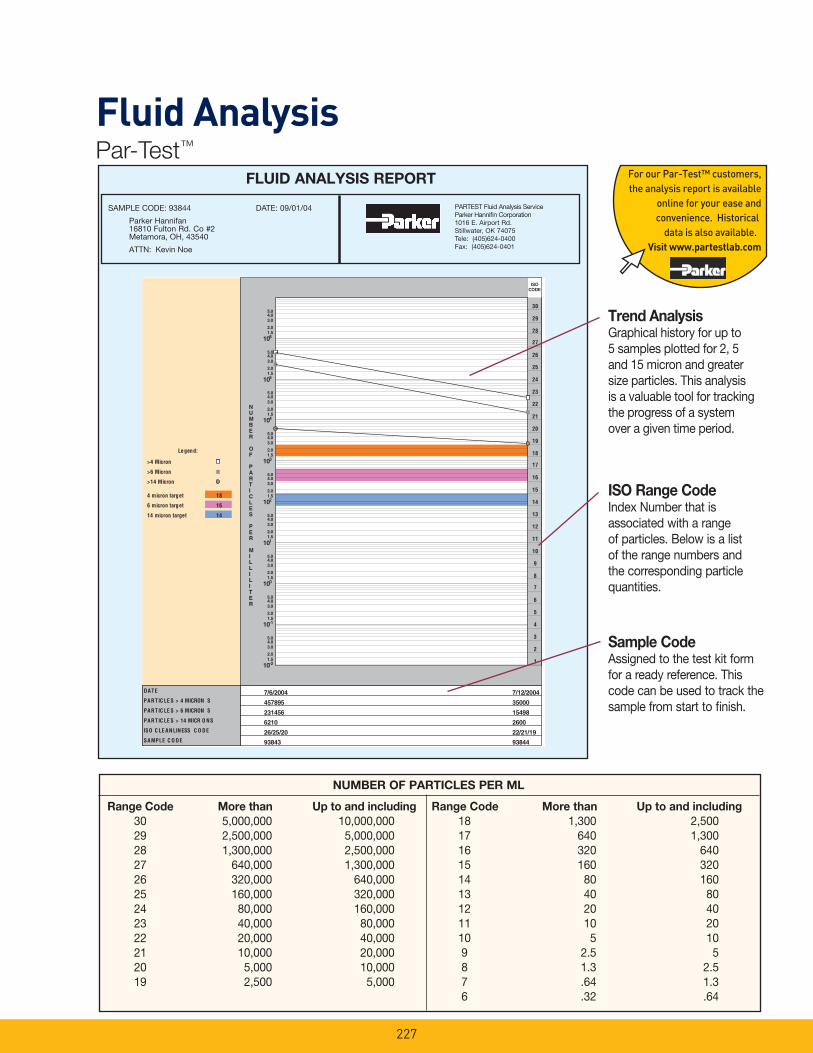
Fluid AnalysisPar-Test™
PARTEST Flu id Anal y sis Ser vicePark er Hannifi n Cor po ra tion1016 E. Airport Rd.Stillwater, OK 74075Tele: (405)624-0400Fax: (405)624-0401
SAMPLE CODE: 93844 DATE: 09/01/04
Parker Hannifan 16810 Fulton Rd. Co #2 Metamora, OH, 43540
ATTN: Kevin Noe
FLUID ANALYSIS REPORT
Range Code More than Up to and in clud ing
30 5,000,000 10,000,000 29 2,500,000 5,000,000 28 1,300,000 2,500,000 27 640,000 1,300,000 26 320,000 640,000 25 160,000 320,000 24 80,000 160,000 23 40,000 80,000 22 20,000 40,000 21 10,000 20,000 20 5,000 10,000 19 2,500 5,000
Range Code More than Up to and including
18 1,300 2,500 17 640 1,300 16 320 640 15 160 320 14 80 160 13 40 80 12 20 40 11 10 20 10 5 10 9 2.5 5 8 1.3 2.5 7 .64 1.3 6 .32 .64
Trend Anal y sisGraphical history for up to 5 samples plotted for 2, 5 and 15 micron and greater size particles. This analysis is a valuable tool for tracking the progress of a system over a given time period.
Sample CodeAssigned to the test kit form for a ready reference. This code can be used to track the sample from start to fi nish.
ISO Range CodeIndex Number that is associated with a range of particles. Below is a list of the range numbers and the corresponding particle quantities.
NUMBER OF PARTICLES PER ML
227
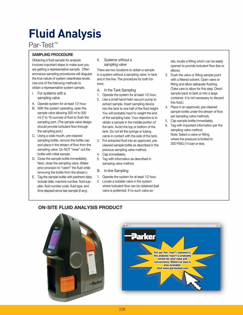
Fluid AnalysisPar-Test™
SAMPLING PROCEDURE
Obtaining a fl uid sample for analysis involves important steps to make sure you are getting a rep re sen ta tive sample. Often erroneous sampling pro ce dures will dis guise the true nature of system cleanliness levels. Use one of the fol low ing methods to obtain a rep re sen ta tive system sample.
I. For systems with a sampling valve
A. Operate system for at least 1/2 hour.B. With the system operating, open the
sample valve al low ing 200 ml to 500 ml (7 to 16 ounc es) of fl uid to fl ush the sampling port. (The sample valve design should provide turbulent fl ow through the sam pling port.)
C. Using a wide mouth, pre-cleaned sampling bottle, re move the bottle cap and place in the stream of fl ow from the sampling valve. Do NOT “rinse” out the bottle with initial sample.
D. Close the sample bottle im me di ate ly. Next, close the sampling valve. (Make prior provision to “catch” the fl uid while removing the bottle from the stream.)
E. Tag the sample bottle with pertinent data; in clude date, machine number, fl uid sup-plier, fl uid number code, fl uid type, and time elapsed since last sample (if any).
II. Systems without asampling valve
There are two locations to obtain a sample in a system without a sampling valve: in-tank and in the line. The pro ce dure for both fol-lows:
A. In the Tank Sampling1. Operate the system for at least 1/2 hour.2. Use a small hand-held vac u um pump to
extract sample. Insert sampling device into the tank to one half of the fl uid height. You will probably have to weight the end of the sampling tube. Your objective is to obtain a sample in the middle portion of the tank. Avoid the top or bottom of the tank. Do not let the syringe or tubing came in contact with the side of the tank.
3. Put extracted fl uid into an approved, pre-cleaned sam ple bottle as described in the previous sam pling valve method.
4. Cap immediately.5. Tag with information as described in
sampling valve method.
B. In-line Sampling
1. Operate the system for at least 1/2 hour.2. Locate a suitable valve in the system
where turbulent fl ow can be obtained (ball valve is pre ferred). If no such valve ex-
ists, locate a fi tting which can be easily opened to provide turbulent fl ow (tee or elbow).
3. Flush the valve or fi tting sample point with a fi ltered solvent. Open valve or fi tting and allow adequate fl ushing. (Take care to allow for this step. Direct sample back to tank or into a large container. It is not necessary to discard this fl uid.)
4. Place in an approved, pre-cleaned sample bottle under the stream of fl ow per sam pling valve methods.
5. Cap sample bottle im me di ate ly.6. Tag with important in for ma tion per the
sampling valve method. Note: Select a valve or fi tting where the pressure is limited to 200 PSIG (14 bar) or less.
ON-SITE FLUID ANALYSIS PRODUCT
228
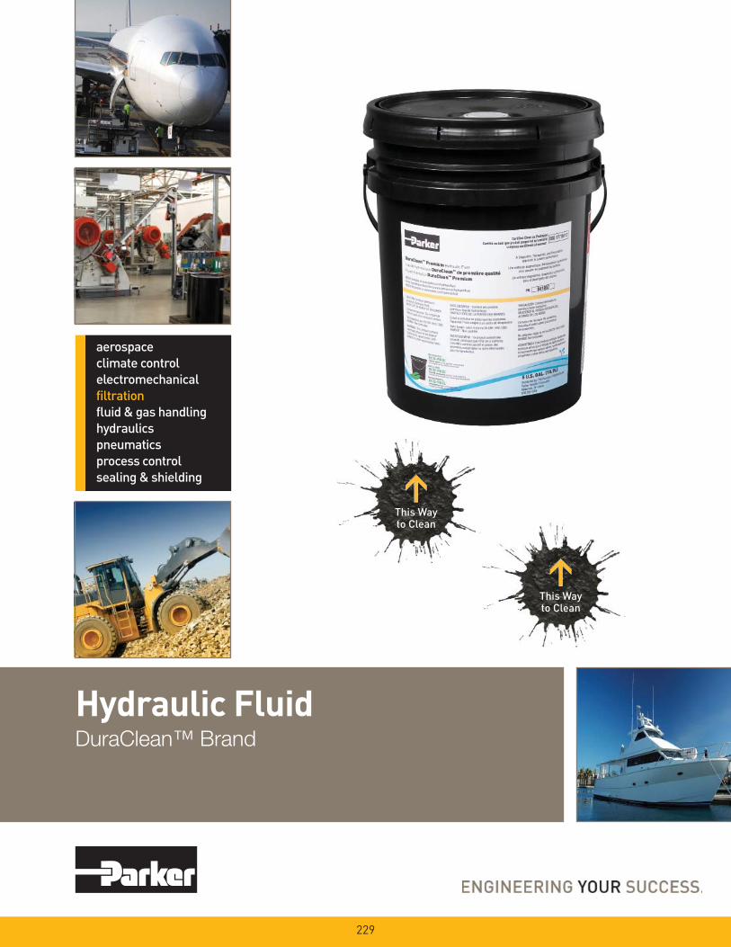
Hydraulic FluidDuraClean™ Brand
229
This Wayto Clean
This Wayto Clean

230
Parker DuraClean™ Starts Clean. Stays Clean.
Package Size Part Number Minimum Order Qty.
Pail (5 gal.) 941907 24
Drum (55 gal.) 942125 4
Tote (275 gal.) 942126 1
DuraClean™ is an ultra premium hydraulic oil provided exclusively by Parker. The fluid has a unique
additive chemistry designed to maximize oil life while providing optimum anti-wear protection for
the components of today’s advanced hydraulic systems.
Performance Features• ISO 46, all season, multigrade hydraulic fluid
• Replaces ISO 32, 46, and 68 monogrades
• API Group II base oil extends oil life
• High viscosity index for wide operating
temperature ranges
• Outstanding oxidation life to maximize
component life
• Prevents varnish formation
• Clean, as packaged, to ISO 17/15/12
cleanliness standard
• Special formulation that allows for rapid air
release and water separation
• Excellent filterability to minimize filter blockage
• Outstanding acrylate anti-foam agent contains
no silicones, which can lead to inacurate
particle counts
• Excellent shear stability for stable viscosity
over time
• Superior thermal stability for uncompromised
performance at high temperatures
• Parker gold dye for easy identification
• Formulated to help extend the life of hoses
and seals
Applications• Drain-and-change for most industrial and
mobile hydraulic systems specifying mineral-
based oil
• Top-treat for replenishing hydraulic systems
already using VG 32, 46, and 68 hydraulic
oils
• Wide operating temperature range
requirements
• High performance hydraulic power units and
equipment
• Systems with high pressures and
temperatures
Performance Approvals• Parker Hannifin HF-0 (Denison HF-0)
• Eaton Vickers brochure 03-401-2010
(M-2950-S and I-286-S)
• Cincinnati Machine P-70
• Meets DIN 51524 Part 3 requirements
• Meets US Steel 127
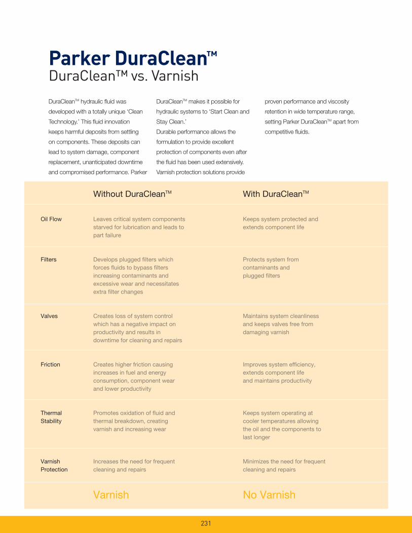
231
DuraCleanTM hydraulic fl uid was
developed with a totally unique ‘Clean
Technology.’ This fl uid innovation
keeps harmful deposits from settling
on components. These deposits can
lead to system damage, component
replacement, unanticipated downtime
and compromised performance. Parker
DuraCleanTM makes it possible for
hydraulic systems to ‘Start Clean and
Stay Clean.’
Durable performance allows the
formulation to provide excellent
protection of components even after
the fl uid has been used extensively.
Varnish protection solutions provide
Without DuraCleanTM With DuraCleanTM
Oil Flow Leaves critical system components Keeps system protected and starved for lubrication and leads to extends component life part failure
Filters Develops plugged fi lters which Protects system from forces fl uids to bypass fi lters contaminants and increasing contaminants and plugged fi lters excessive wear and necessitates extra fi lter changes
Valves Creates loss of system control Maintains system cleanliness which has a negative impact on and keeps valves free from productivity and results in damaging varnish downtime for cleaning and repairs
Friction Creates higher friction causing Improves system effi ciency, increases in fuel and energy extends component life consumption, component wear and maintains productivity and lower productivity
Thermal Promotes oxidation of fl uid and Keeps system operating atStability thermal breakdown, creating cooler temperatures allowing varnish and increasing wear the oil and the components to last longer
Varnish Increases the need for frequent Minimizes the need for frequentProtection cleaning and repairs cleaning and repairs
Varnish No Varnish
Parker DuraClean™ DuraClean™ vs. Varnish
proven performance and viscosity
retention in wide temperature range,
setting Parker DuraCleanTM apart from
competitive fl uids.
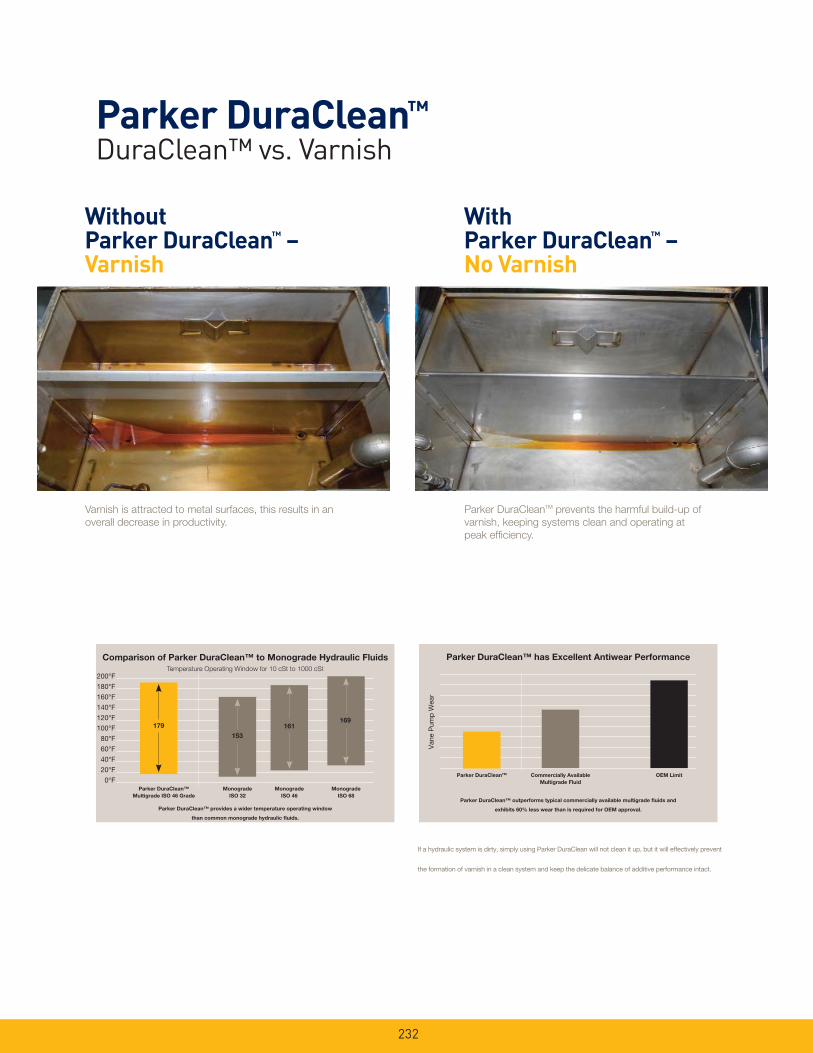
232
Parker DuraClean™ DuraClean™ vs. Varnish
Varnish is attracted to metal surfaces, this results in an
overall decrease in productivity.
Parker DuraCleanTM prevents the harmful build-up of
varnish, keeping systems clean and operating at
peak effi ciency.
Without Parker DuraClean™ – Varnish
With Parker DuraClean™ – No Varnish
If a hydraulic system is dirty, simply using Parker DuraClean will not clean it up, but it will effectively prevent
the formation of varnish in a clean system and keep the delicate balance of additive performance intact.
Parker DuraClean™ has Excellent Antiwear Performance
Parker DuraCleanTM Commercially Available
Multigrade Fluid
OEM Limit
Van
e P
ump
Wea
r
Parker DuraClean™ outperforms typical commercially available multigrade fl uids and
exhibits 60% less wear than is required for OEM approval.
Comparison of Parker DuraClean™ to Monograde Hydraulic Fluids
Temperature Operating Window for 10 cSt to 1000 cSt
Monograde
ISO 32
Monograde
ISO 46
200°F
180°F
160°F
140°F
120°F
100°F
80°F
60°F
40°F
20°F
0°FParker DuraClean™
Multigrade ISO 46 Grade
Monograde
ISO 68
179
153
161169
Parker DuraClean™ provides a wider temperature operating window
than common monograde hydraulic fl uids.

Reservoir AccessoriesFiller Breathers, Strainers, Diffusers,
Fluid Level/Temperature Gauges
233

234
Specifi cations:Materials: Body: Non-corrodible glass fi lled nylon.Valve: Nylon/Nitrile.Dipstick: ABS, acetal Hi/Lo indicators.
Filtration Element: Expanded polyurethane foam, 10 micron.
Operating Temperatures: -22oF (-30oC) to 195oF (90oC).
Seals: Nitrile (single-hole), cork gasket (six-hole).
Pressurization Options: 3 psi (0.2 bar).
Dipstick: (optional) 7.9 in. (200 mm) or 15.8 in. (400 mm) lengths with adjustable Hi/Lo indicators.
Telescopic Strainer
Anti-Splash
Design!
(Non-pressurized)US GALS/SEC (air)
0.25
0.20
0.15
0.10
0.05
Flow 1/sec (air)
PSI
3.625
2.9
2.175
1.45
0.275
0
0 1.32 2.64 3.96
Diff
eren
tial P
ress
ure
(bar
)
0 5 10 15
1.2
1.0
0.8
0.6
0.4
0.2
0
Diff
eren
tial P
ress
ure
(bar
)
Flow l/sec (air)
PSI
17.4
14.5
11.6
8.7
5.8
2.9
0
US GALS/SEC (air)0 1.32 2.64 3.96
(Pressurized)
3psi (.2 bar) valve
Single-Hole Option Six-Hole Option
NOTE: REFER TO UCC PRODUCTIONINSTRUCTIONS FOR ASSEMBLY DETAILSAND PACKING REQUIREMENTS
TANK MOUNTING HOLE Ø63
Ø101
70
271
Ø42
Ø311.22
1.65
3.98
2.76
10.6
7
Ø101
167
10
Ø42
70
1.65
2.76
.39
6.57
3.98
MA
X
Ø101
72
167
A
.164.06x Ø
2.7670
1.65
6.57
2.83
3.98
Ø42
Linear Measurement= mmin
Non-pressurized
AB.98812021.UC 3 psi (.2 bar) with telescopic strainer
Six-Hole
New Part No. Description
FB1.D1A1B2P
FB1.D1A1C2P
AB.98210011.UC
AB.98210021.UC
Filler breather with 3.7" (95 mm)
strainer
Filler breather with telescopic strainer
Single-Hole
New Part No.
Six-Hole
Obs. Part No. Description
Pressurized
(6)-#10x.5
(6)-#10x.5
(6)-#10x.5
*Mounting screws for six-hole only
10
10
10
Micron Rating Screws*
Micron Rating Screws*
B.68.206
B.68.207
Dipsticks
Pack of (10) x 7.9"
Pack of (10) x 15.8"
Not Available
Single-Hole
Part No.
DescriptionNew Part Number
AB.98810011.UC
AB.98810021.UC
Six-Hole
New Part No.
FB1.A1A1B2P
FB1.A1A1C2P
Single-Hole
Obs. Part No.
FB1.D1B1C2P
Six-Hole
Obs. Part No.
DIP.FB2
DIP.FB4
Obsolete Part Number
Reservoir AccessoriesNon-Metallic Filler Breathers
Drawings are for reference only. Contact factory for current version.
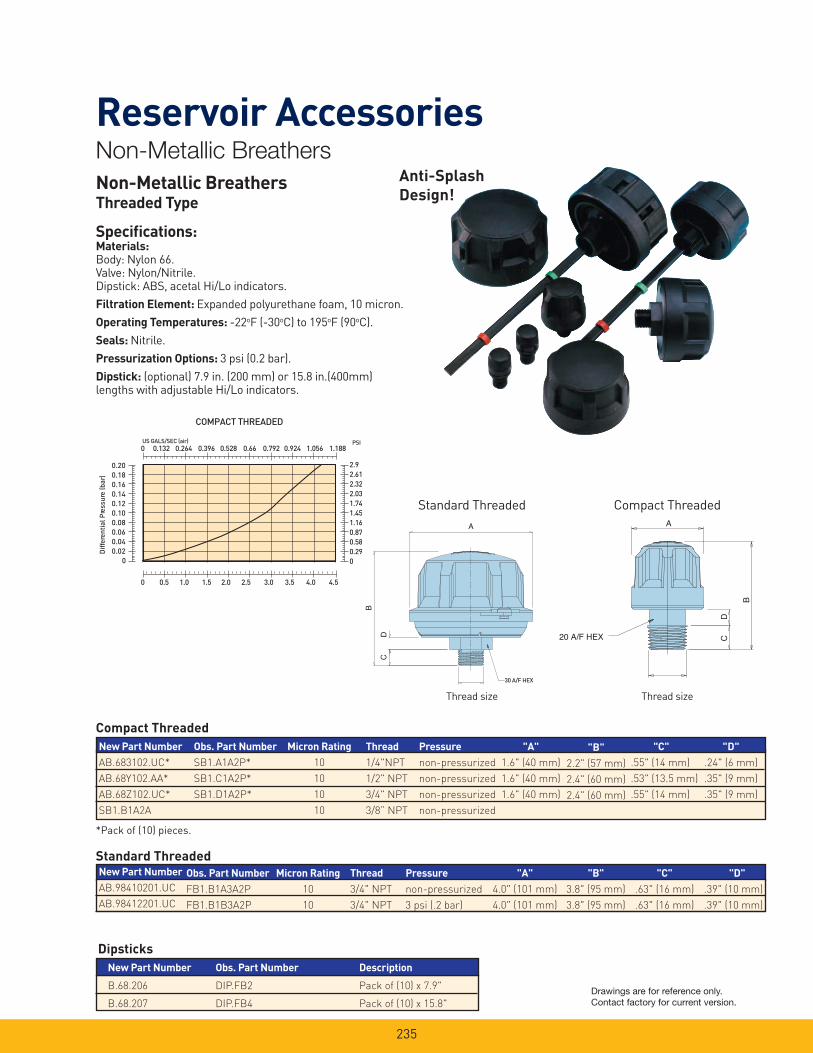
235
Reservoir AccessoriesNon-Metallic Breathers
A
30 A/F HEX
DC
B
Non-Metallic BreathersThreaded Type
Specifi cations:Materials: Body: Nylon 66.Valve: Nylon/Nitrile.Dipstick: ABS, acetal Hi/Lo indicators.
Filtration Element: Expanded polyurethane foam, 10 micron.
Operating Temperatures: -22oF (-30oC) to 195oF (90oC).
Seals: Nitrile.
Pressurization Options: 3 psi (0.2 bar).
Dipstick: (optional) 7.9 in. (200 mm) or 15.8 in.(400mm) lengths with adjustable Hi/Lo indicators.
B
20 A/F HEX CD
A
Standard Threaded Compact Threaded
0 0.5 1.0 1.5 2.0 2.5 3.0 3.5 4.0 4.5
0.200.180.160.140.120.100.080.060.040.02
0
Diff
eren
tial
Pre
ssur
e (b
ar)
US GALS/SEC (air)0 0.132 0.264 0.396 0.528 0.66 0.792 0.924 1.056 1.188
PSI
2.92.612.322.031.741.451.160.870.580.290
COMPACT THREADED
Anti-Splash
Design!
Thread size Thread size
Compact Threaded
Dipsticks
Description
Pack of (10) x 7.9"
Pack of (10) x 15.8"
New Part Number
B.68.206
B.68.207
New Part Number
AB.683102.UC*
AB.68Y102.AA*
AB.68Z102.UC*
SB1.B1A2A
Standard Threaded
Micron Rating
10
10
Micron Rating
10
10
10
10
Thread
3/4" NPT
3/4" NPT
Thread
1/4"NPT
1/2" NPT
3/4" NPT
3/8” NPT
"B"
2.2" (57 mm)
2.4" (60 mm)
2.4" (60 mm)
"A"
1.6" (40 mm)
1.6" (40 mm)
1.6" (40 mm)
"C"
.55" (14 mm)
.53" (13.5 mm)
.55" (14 mm)
"D"
.24" (6 mm)
.35" (9 mm)
.35" (9 mm)
"B"
3.8" (95 mm)
3.8" (95 mm)
"A"
4.0" (101 mm)
4.0" (101 mm)
"C"
.63" (16 mm)
.63" (16 mm)
"D"
.39" (10 mm)
.39" (10 mm)
Pressure
non-pressurized
3 psi (.2 bar)
Pressure
non-pressurized
non-pressurized
non-pressurized
non-pressurized
*Pack of (10) pieces.
New Part Number
AB.98410201.UC
AB.98412201.UC
Obs. Part Number
SB1.A1A2P*
SB1.C1A2P*
SB1.D1A2P*
Obs. Part Number
FB1.B1A3A2P
FB1.B1B3A2P
Obs. Part Number
DIP.FB2
DIP.FB4
Drawings are for reference only. Contact factory for current version.
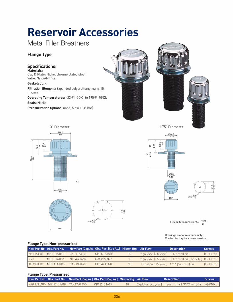
236
Reservoir AccessoriesMetal Filler Breathers
Flange Type
Specifi cations:Materials: Cap & Plate: Nickel chrome plated steel.Valve: Nylon/Nitrile.
Gasket: Cork.
Filtration Element: Expanded polyurethane foam, 10 micron.
Operating Temperatures: -22oF (-30oC) to 195oF (90oC).
Seals: Nitrile.
Pressurization Options: none, 5 psi (0.35 bar).
3xØ
1.75
1.44
4.33
1.85
1.10
1.63
.16
Ø44.5
36.5
4711
0
Ø28
Ø514.0
41.3
3" Diameter 1.75" Diameter
3.00
1.71
1.95
6.04
2.29
3.27
2.76
.16
Ø76. 2
43.4
58.2
Ø49.5
Ø83
6xØ 4.0
A
153.
5
70
Linear Measurement= mmin
New Part No.
AB.1163.10
5561
AB.1380.10
New Part No.
PAB.1730.10.5
Description
3" (76 mm) dia.
3" (76 mm) dia., w/lck lug
1.75" (44.5 mm) dia.
Description
5 psi (.35 bar), 3" (76 mm)dia.
New Part (Cap As.)
CAP.1730.40.5
New Part (Cap As.)
CAP.1163.10
Not Available
CAP.1380.40
Flange Type, Non-pressurized
Flange Type, Pressurized
Micron Rtg.
10
Micron Rtg
10
10
10
Screws
(6)-#10x.5
Air Flow
2 gal./sec. (7.5 l/sec.)
Air Flow
2 gal./sec. (7.5 l/sec.)
2 gal./sec. (7.5 l/sec.)
1.3 gal./sec. (5 l/sec.)
Screws
(6)-#10x.5
(6)-#10x.5
(6)-#10x.5
Obs. Part No.
MB1.D1A1B1P
MB1.D1A1B2P
MB1.A1A1B1P
Obs. Part (Cap As.)
CP1.D1A1A1P
Not Available
CP1.A2A1A1P
Obs.Part (Cap As.)
CP1.D1C1A1P
Obs. Part No.
MB1.D1C1B1P
Drawings are for reference only. Contact factory for current version.

237
Reservoir AccessoriesMetal BreathersThreaded Type
Specifi cations:Materials: Cap & Plate: Nickel chrome plated steel.Valve: Nylon/Nitrile.
Gasket: Cork.
Filtration Element: Expanded polyurethane foam, 10 micron.
Operating Temperatures: -22oF (-30oC) to 195oF (90oC).
Seals: Nitrile.
Pressurization Options: none, 5 psi (0.35 bar).
43.4
6
3/4” NPT
35 1.38
Ø76.2
16 65.63
2.561.
71.2
4
3.00
Ø44.5
16 .63
13 56.536
.57
1/4” NPT
2.22
.51
.28
1.44
1.75
¾" Threaded ¼" Threaded
Linear Measurement= mmin
Description
3" (76 mm) diameter
1.75" (44.5 mm) diameter
Threaded, Non-pressurized
Micron Rating
10
10
Thread
3/4" NPT
1/4" NPT
Air Flow
1.3 gallon/sec. (5 l/sec.)
.7 gallon/sec. (2.5 l/sec.)
New Part Number
SAB.1562.10.NPT
SAB.1563.10.NPT
Obs. Part Number
MB1.B1A3A1P
MB1.C1A3A1P
Drawings are for reference only. Contact factory for current version.
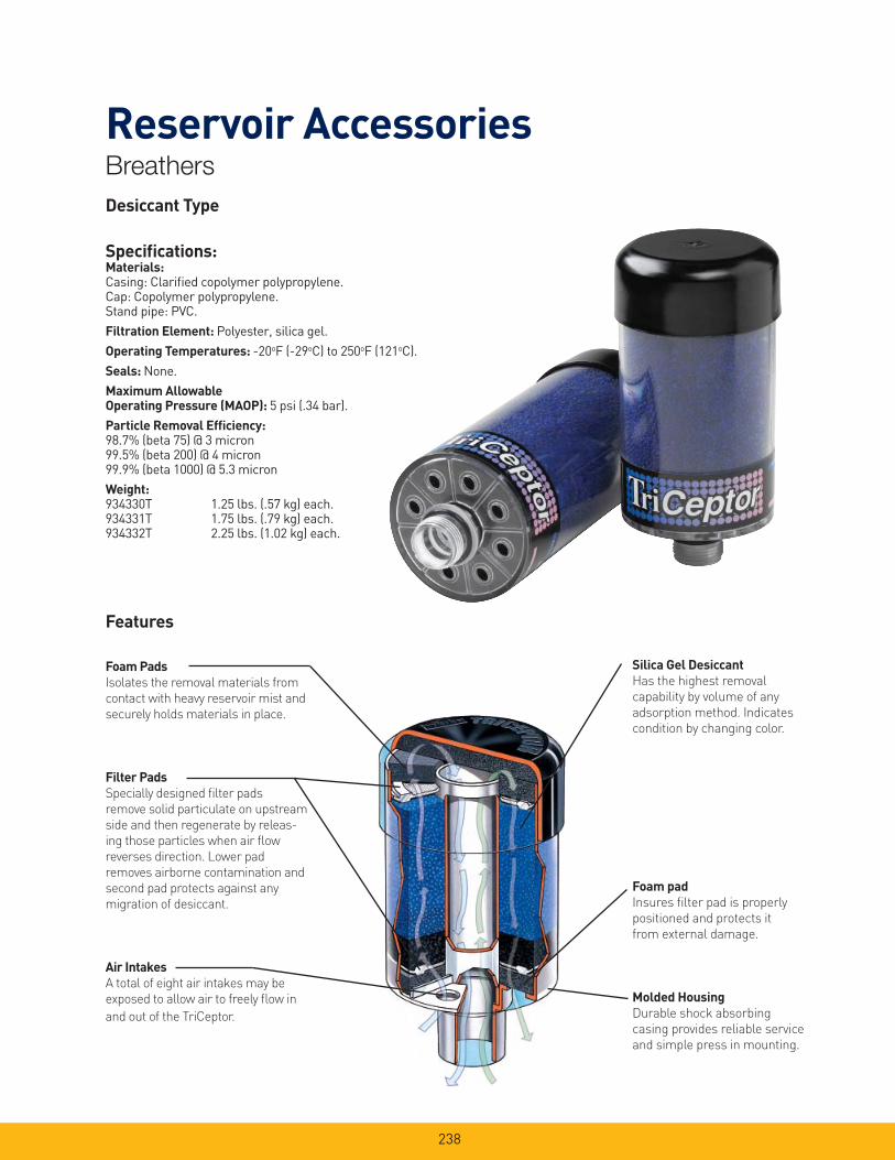
238
Reservoir AccessoriesBreathers
Foam Pads
Isolates the removal materials from
contact with heavy reservoir mist and
securely holds materials in place.
Filter Pads
Specially designed fi lter pads
remove solid particulate on upstream
side and then regenerate by releas-
ing those particles when air fl ow
reverses direction. Lower pad
removes airborne contamination and
second pad protects against any
migration of desiccant.
Air Intakes
A total of eight air intakes may be
exposed to allow air to freely fl ow in
and out of the TriCeptor.
Desiccant Type
Specifi cations:Materials: Casing: Clarifi ed copolymer polypropylene.Cap: Copolymer polypropylene.Stand pipe: PVC.
Filtration Element: Polyester, silica gel.
Operating Temperatures: -20oF (-29oC) to 250oF (121oC).
Seals: None.
Maximum Allowable Operating Pressure (MAOP): 5 psi (.34 bar).
Particle Removal Effi ciency: 98.7% (beta 75) @ 3 micron99.5% (beta 200) @ 4 micron99.9% (beta 1000) @ 5.3 micron
Weight: 934330T 1.25 lbs. (.57 kg) each.934331T 1.75 lbs. (.79 kg) each.934332T 2.25 lbs. (1.02 kg) each.
Silica Gel Desiccant
Has the highest removal
capability by volume of any
adsorption method. Indicates
condition by changing color.
Foam pad
Insures fi lter pad is properly
positioned and protects it
from external damage.
Molded Housing
Durable shock absorbing
casing provides reliable service
and simple press in mounting.
Features

239
Reservoir AccessoriesBreathers
0 4 8 12 16 20
PSI
D BA
R
2.5
2.0
1.5
1.0
.5
0
3.0
SCFM
Liters/Second
0 1.88 3.78 5.66 7.55 9.44
3.5 .241
.207
.172
.138
.103
.068
.034
0 30 60 90 120 150
PSID
BAR
2.5
2.0
1.5
1.0
.5
0
3.0
3.5 .241
.207
.172
.138
.103
.068
.034
GPM (fluid exchange rate)
Installation
TriCeptor breathers are designed for simple installation
on most equipment, regardless of mounting connection.
Since TriCeptor breathers are disposable, the threaded
connection allows for quick and easy maintenance. Several
mounting adapters (shown below) are available to provide
the desired mounting. The installation/replacement pro-
cess consists of four easy steps:
1. Remove from protective plastic wrap.
2. Remove 1" blue cap from standpipe.
3. Remove foil label to expose the necessary
amount of air intake holes.
4. Twist TriCeptor into mounting adapter.
Servicing the TriCeptor breather is also very easy. When
the silica gel changes color from blue to a pink, the
breather is no longer active and needs to be replaced.
Simply remove the unit and discard properly.
Air Flow Performance
The curves below show the air fl ow performance of the
three TriCeptor breathers. To insure the longest life
possible, the initial clean pressure drop should not
exceed 1.5 psid (.103 bar).
Field Adapter Flange Adapter
Linear Measurement= mmin
'B''A'
4.00101.60
O-RING
1" THREADED CONNECTION
Part Number ‘A’ (mm/in) ‘B’ (mm/in) Quantity
934330T 155.58/6.125 135.256/5.325 6 pcs.
934331T 206.38/8.125 186.06/7.325 6 pcs.
934332T 257.18/10.125 236.86/9.325 6 pcs.
937546 Field Adapter 937546 1 pc.
937463 Flange Adapter 937463 1 pc.
Drawings are for reference only. Contact factory for current version.
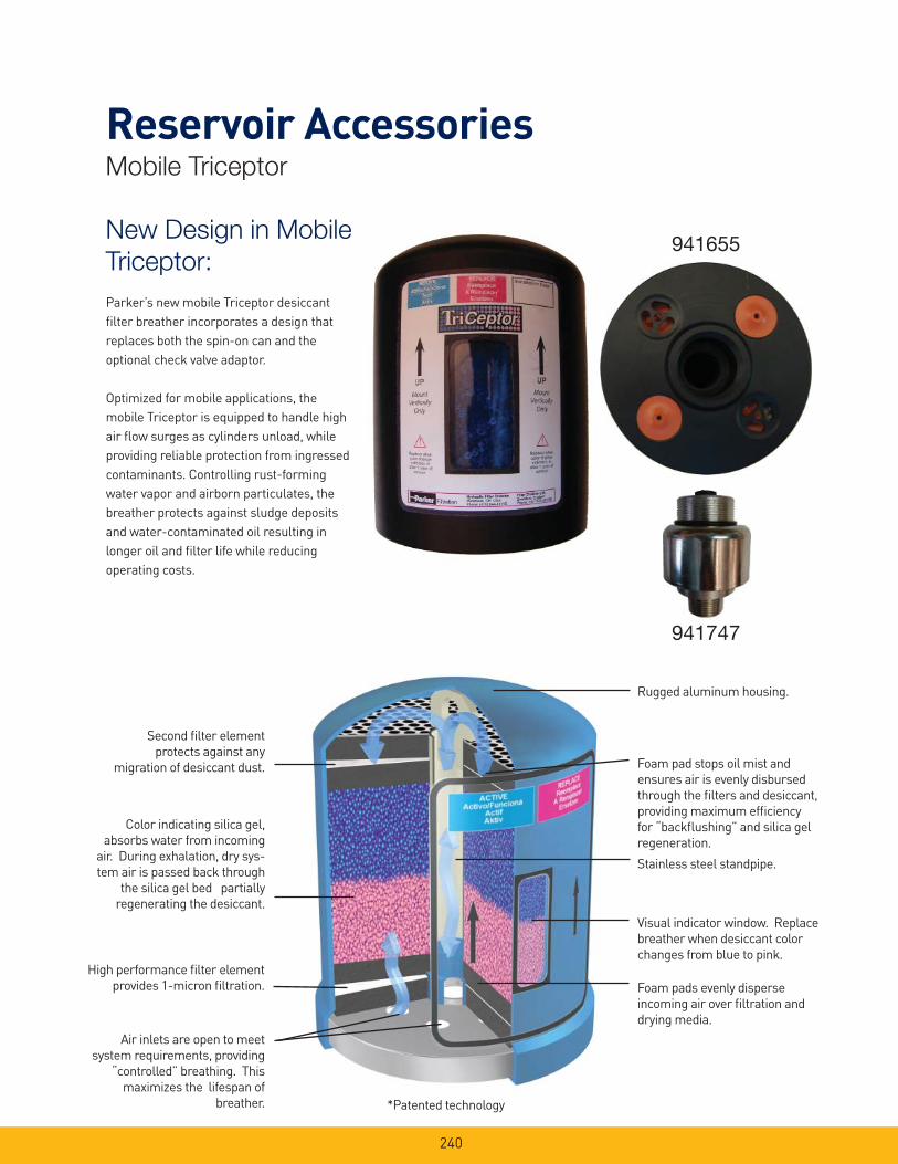
240
Reservoir AccessoriesMobile Triceptor
New Design in Mobile
Triceptor:
Parker’s new mobile Triceptor desiccant
fi lter breather incorporates a design that
replaces both the spin-on can and the
optional check valve adaptor.
Optimized for mobile applications, the
mobile Triceptor is equipped to handle high
air fl ow surges as cylinders unload, while
providing reliable protection from ingressed
contaminants. Controlling rust-forming
water vapor and airborn particulates, the
breather protects against sludge deposits
and water-contaminated oil resulting in
longer oil and fi lter life while reducing
operating costs.
941655
941747
Air inlets are open to meet
system requirements, providing
“controlled” breathing. This
maximizes the lifespan of
breather.
High performance fi lter element
provides 1-micron fi ltration.
Color indicating silica gel,
absorbs water from incoming
air. During exhalation, dry sys-
tem air is passed back through
the silica gel bed partially
regenerating the desiccant.
Second fi lter element
protects against any
migration of desiccant dust.
*Patented technology
Rugged aluminum housing.
Foam pad stops oil mist and
ensures air is evenly disbursed
through the fi lters and desiccant,
providing maximum effi ciency
for “backfl ushing” and silica gel
regeneration.
Stainless steel standpipe.
Visual indicator window. Replace
breather when desiccant color
changes from blue to pink.
Foam pads evenly disperse
incoming air over fi ltration and
drying media.

241
Reservoir AccessoriesMobile Triceptor
Amount of Silica Gel0.79 kg
1 lb. 12 ox.
Adsorption Capacity318 mL
1.34 cups
Net Weight of Unit1.8 kg
4 lbs. 3 oz.
Filtration Area 31.1 in2 / 79 cm2
Direction of Flow Bidirectional
Operating Temperature Range-20°F to 300°F /-29°C to 148.89°C
General Data
Material EPTFE
Porosity3.5 - 7.5 Ft./min.@ 0.5 in. - H2O(ASTM D 737)
Filtration Effi ciency 99.97% @ 0.3μ(IES-RP-CC021.1)
Filter Media
Material Nylon and MXD6
Maximum Operating Temperature 300°F / 148.89°C
Melting Point 320°F / 160°C
Check Valve Adapter Zinc Plated Steel
Unit Material Data
Apparent Bulk Density 700 - 800 kg/m3
Average Particle Diameter 0.145” / 3.68 mm
Specifi c Heat 0.25 BTU/lb. F
Nomimal Mesh Range 4 x 8
Average Crush Strength 35 lbs. / 15.9 kg
Hygroscopic Agent (Silica Gel)
1 1/2” - 16 UNFemale Thread
0.17”0.43 cm
5.1”12.95 cm
6.51”16.54 cm
Note: Element removal clearance = 1”
1 1/2” - 16 UNMale Thread
O-Ring
3/4” NPTMale Thread
2.3”
Check Valve AdapterPart Number 941747
3.1”2.4”
Drawings are for reference only. Contact factory for current version.
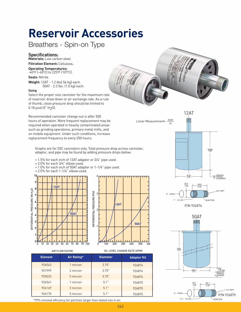
242
168.16.62
MINCANNISTER
REMOVALCLEARANCE
31.81.25130.1
5.12
Specifi cations:Materials: Low carbon steel.
Filtration Element: Cellulose.
Operating Temperatures:-40oF (-40oC) to 225oF (107oC).
Seals: Nitrile.
Weight: 12AT - 1.2 lbs(.54 kg) each. 50AT - 2.3 lbs. (1.0 kg) each.
Sizing
Select the proper size cannister for the maximum rate
of reservoir draw down or air exchange rate. As a rule
of thumb, clean pressure drop should be limited to
0.18 psid (5" H2O).
Recommended cannister change out is after 500
hours of operation. More frequent replacement may be
required when operated in heavily contaminated areas
such as grinding operations, primary metal mills, and
on mobile equipment. Under such conditions, increase
replacement frequency to every 250 hours.
0 10 20 30 40 50 60 70 80 90 100
12AT
50AT
DIF
FER
ENTI
AL P
RES
SUR
E (P
SI)
AIR FLOW (SCFM) OIL LEVEL CHANGE RATE (GPM)
12AT
0
1
2
3
4
5
6
7
8
9
10
0
1
2
3
4
5
6
7
8
9
10
50AT.1
.2
.3
.4
0 100 200 300 400 500 600
DIF
FER
ENTI
AL
PR
ESSU
RE
(IN
H20
)
P/N 926876
12AT
50AT
95.253.75”
148.845.68
MINIMUMREMOVALCLEARANCE
15.7.62
O - RING
1½” - 16 UN
42.71.05
85.13.35
ADAPTER
O - RING
1” - 12 UN
26.71.05
66.82.63
ADAPTER
Linear Measurement= mmin
Graphs are for 03C cannisters only. Total pressure drop across cannister, adaptor, and pipe may be found by adding pressure drops below:
+ 1.5% for each inch of 12AT adapter or 3/4" pipe used.+ 3.0% for each 3/4" elbow used.+ 1.0% for each inch of 50AT adapter or 1-1/4" pipe used.+ 2.0% for each 1-1/4" elbow used.
Reservoir AccessoriesBreathers - Spin-on Type
3/4” NPT
1 1/4” NPT
P/N 926875
*99% removal effi ciency for particles larger than stated size in air.
Air Rating*
1 micron
2 micron
5 micron
1 micron
2 micron
5 micron
Element
926543
921999
925023
926541
926169
926170
Adaptor Kit
926876
926876
926876
926875
926875
926875
Diameter
3.75"
3.75"
3.75"
5.1"
5.1"
5.1"
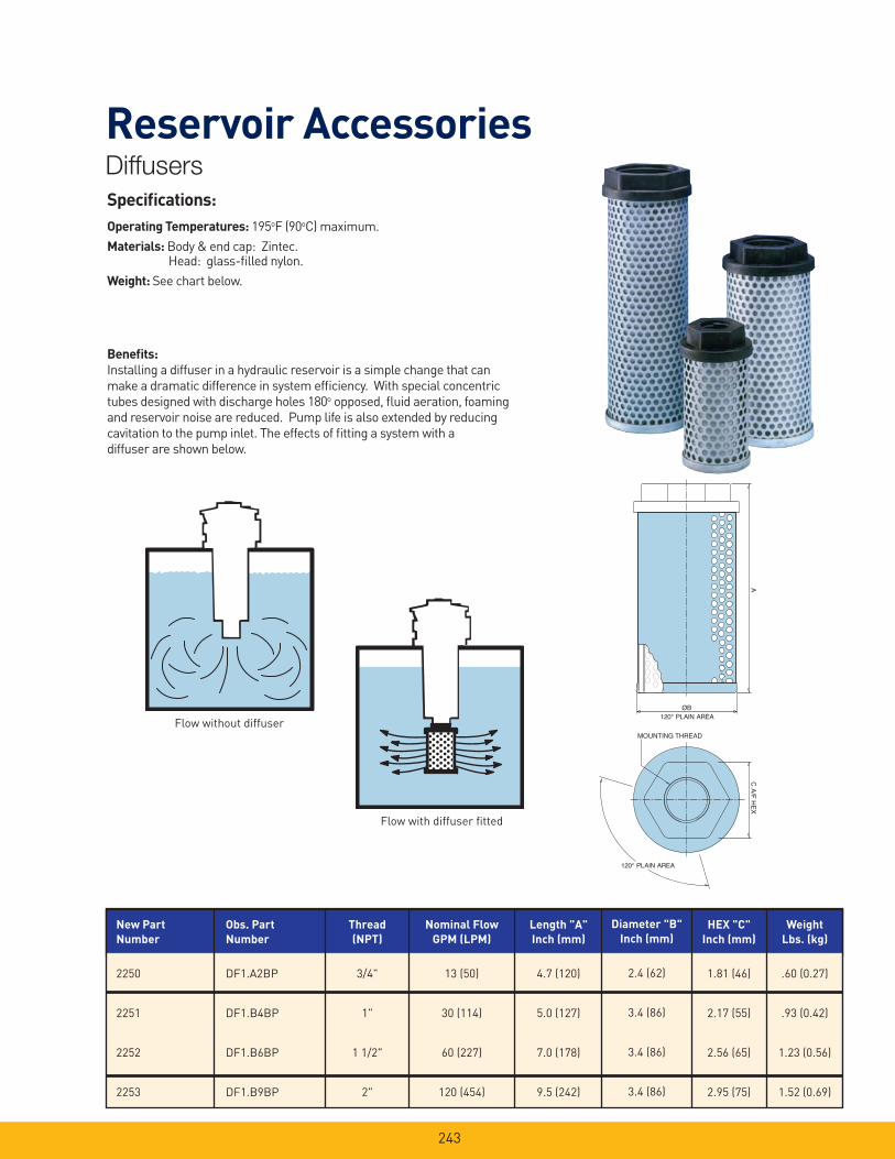
243
Reservoir AccessoriesDiffusers
Specifi cations:
Operating Temperatures: 195oF (90oC) maximum.
Materials: Body & end cap: Zintec. Head: glass-fi lled nylon.
Weight: See chart below.
Benefi ts:
Installing a diffuser in a hydraulic reservoir is a simple change that can
make a dramatic difference in system effi ciency. With special concentric
tubes designed with discharge holes 180o opposed, fl uid aeration, foaming
and reservoir noise are reduced. Pump life is also extended by reducing
cavitation to the pump inlet. The effects of fi tting a system with a
diffuser are shown below.
Flow without diffuser
Flow with diffuser fi tted
A
ØB
MOUNTING THREAD
120° PLAIN AREA
C A
/F H
EX
120° PLAIN AREA
New Part
Number
2250
2251
2252
2253
Thread
(NPT)
3/4"
1"
1 1/2"
2"
Nominal Flow
GPM (LPM)
13 (50)
30 (114)
60 (227)
120 (454)
Length "A"
Inch (mm)
4.7 (120)
5.0 (127)
7.0 (178)
9.5 (242)
Diameter "B"
Inch (mm)
2.4 (62)
3.4 (86)
3.4 (86)
3.4 (86)
Weight
Lbs. (kg)
.60 (0.27)
.93 (0.42)
1.23 (0.56)
1.52 (0.69)
HEX "C"
Inch (mm)
1.81 (46)
2.17 (55)
2.56 (65)
2.95 (75)
Obs. Part
Number
DF1.A2BP
DF1.B4BP
DF1.B6BP
DF1.B9BP
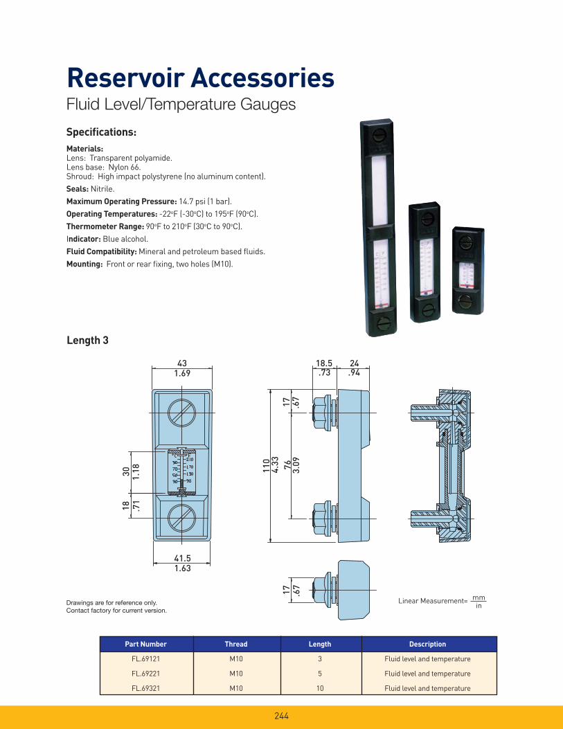
244
Reservoir AccessoriesFluid Level/Temperature Gauges
Specifi cations:
Materials: Lens: Transparent polyamide.Lens base: Nylon 66.Shroud: High impact polystyrene (no aluminum content).
Seals: Nitrile.
Maximum Operating Pressure: 14.7 psi (1 bar).
Operating Temperatures: -22oF (-30oC) to 195oF (90oC).
Thermometer Range: 90oF to 210oF (30oC to 90oC).
Indicator: Blue alcohol.
Fluid Compatibility: Mineral and petroleum based fl uids.
Mounting: Front or rear fi xing, two holes (M10).
18.5
17
24
76110
43
41.5
3018
17
1.69
1.18
.71
1.63
4.33
3.09
.67
.67
.73 .94
Linear Measurement= mmin
Length 3
Part Number Thread Length Description
FL.69121 M10 3 Fluid level and temperature
FL.69221 M10 5 Fluid level and temperature
FL.69321 M10 10 Fluid level and temperature
Drawings are for reference only. Contact factory for current version.

245
Reservoir AccessoriesFluid Level/Temperature Gauges
43
41.5
2274
17
161
127
17
18.5 24
24
1725
4
288
17
43
41.5
2220
2
1.69
2.91
.87
1.63
1.69
7.95
.87
1.63 .67
10.0
0
11.3
4
.67
.94
.67
6.34
5.00
.67
.73 .94
Linear Measurement= mmin
Length 5
Length 10
Drawings are for reference only. Contact factory for current version.
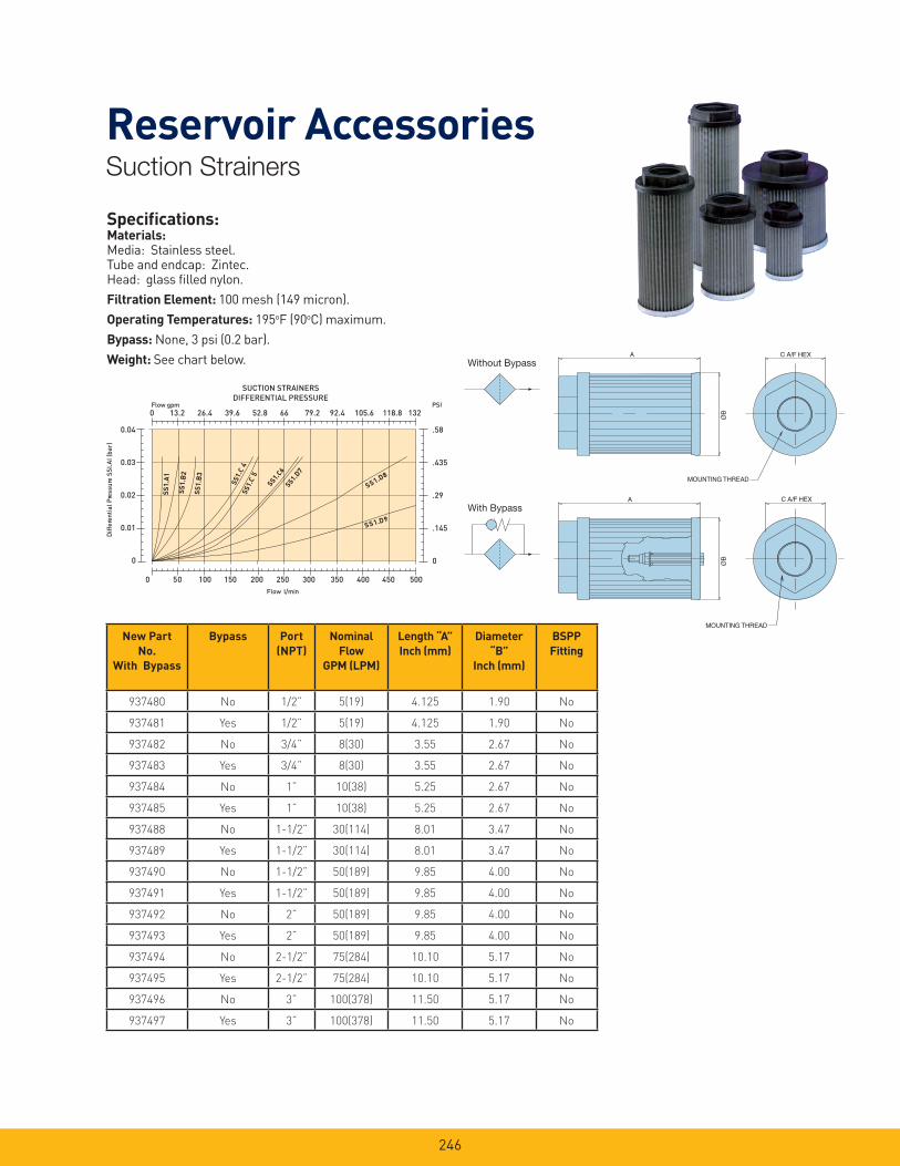
246
Specifi cations:Materials: Media: Stainless steel.Tube and endcap: Zintec.Head: glass fi lled nylon.
Filtration Element: 100 mesh (149 micron).
Operating Temperatures: 195oF (90oC) maximum.
Bypass: None, 3 psi (0.2 bar).
Weight: See chart below.
0 50 100 150 200 250 300 350 400 450 500
SUCTION STRAINERSDIFFERENTIAL PRESSURE
SS1.D9
0.04
0.03
0.02
0.01
0
SS1.D8
SS1.D7
SS1.C6
SS1.
C5
SS1.
C4
SS1.
B3
SS1.
B2
SS1.
A1
Diff
eren
tial
Pre
ssur
e SS
I.AI (
bar)
Flow l/min
Flow gpm0 13.2 26.4 39.6 52.8 66 79.2 92.4 105.6 118.8 132
PSI
.58
.435
.29
.145
0
SS1.D9
SS1.D8
SS1.D7
SS1.C6
SS1.
C5
SS1.
C4
SS1.
B3
SS1.
B2
SS1.
A1
With Bypass
Without BypassA
ØB
C A/F HEX
MOUNTING THREAD
A
ØB
C A/F HEX
MOUNTING THREAD
Reservoir AccessoriesSuction Strainers
New Part
No.
With Bypass
Bypass Port
(NPT)
Nominal
Flow
GPM (LPM)
Length “A”
Inch (mm)
Diameter
“B”
Inch (mm)
BSPP
Fitting
937480 No 1/2” 5(19) 4.125 1.90 No
937481 Yes 1/2” 5(19) 4.125 1.90 No
937482 No 3/4” 8(30) 3.55 2.67 No
937483 Yes 3/4” 8(30) 3.55 2.67 No
937484 No 1” 10(38) 5.25 2.67 No
937485 Yes 1” 10(38) 5.25 2.67 No
937488 No 1-1/2” 30(114) 8.01 3.47 No
937489 Yes 1-1/2” 30(114) 8.01 3.47 No
937490 No 1-1/2” 50(189) 9.85 4.00 No
937491 Yes 1-1/2” 50(189) 9.85 4.00 No
937492 No 2” 50(189) 9.85 4.00 No
937493 Yes 2” 50(189) 9.85 4.00 No
937494 No 2-1/2” 75(284) 10.10 5.17 No
937495 Yes 2-1/2” 75(284) 10.10 5.17 No
937496 No 3” 100(378) 11.50 5.17 No
937497 Yes 3” 100(378) 11.50 5.17 No
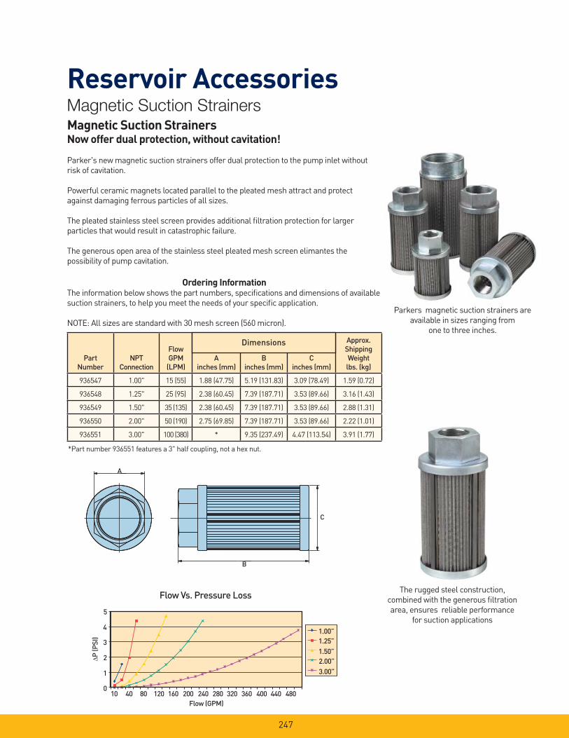
247
Reservoir AccessoriesMagnetic Suction StrainersMagnetic Suction StrainersNow offer dual protection, without cavitation!
Parker's new magnetic suction strainers offer dual protection to the pump inlet without
risk of cavitation.
Powerful ceramic magnets located parallel to the pleated mesh attract and protect
against damaging ferrous particles of all sizes.
The pleated stainless steel screen provides additional fi ltration protection for larger
particles that would result in catastrophic failure.
The generous open area of the stainless steel pleated mesh screen elimantes the
possibility of pump cavitation.
Parkers magnetic suction strainers are
available in sizes ranging from
one to three inches.
Ordering InformationThe information below shows the part numbers, specifi cations and dimensions of available
suction strainers, to help you meet the needs of your specifi c application.
NOTE: All sizes are standard with 30 mesh screen (560 micron).
PartNumber
NPTConnection
FlowGPM
(LPM)A
inches (mm)B
inches (mm)C
inches (mm)
Approx.ShippingWeightlbs. (kg)
936547 1.00" 15 (55) 1.88 (47.75) 5.19 (131.83) 3.09 (78.49) 1.59 (0.72)
936548 1.25" 25 (95) 2.38 (60.45) 7.39 (187.71) 3.53 (89.66) 3.16 (1.43)
936549 1.50" 35 (135) 2.38 (60.45) 7.39 (187.71) 3.53 (89.66) 2.88 (1.31)
936550 2.00" 50 (190) 2.75 (69.85) 7.39 (187.71) 3.53 (89.66) 2.22 (1.01)
936551 3.00" 100 (380) * 9.35 (237.49) 4.47 (113.54) 3.91 (1.77)
Dimensions
A
C
B
Flow Vs. Pressure Loss
Flow (GPM)
P (P
SI)
10 40 80 120 160 200 240 280 320 360 400 440 480
5
4
3
2
1
0
1.00”1.25”1.50”2.00”3.00”
The rugged steel construction,
combined with the generous fi ltration
area, ensures reliable performance
for suction applications
*Part number 936551 features a 3" half coupling, not a hex nut.

248
Notes
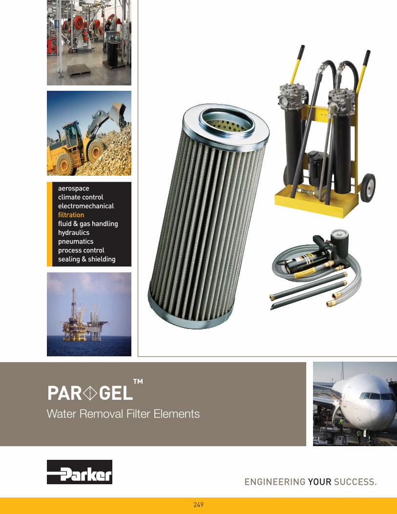
Water Removal Filter Elements
PAR GEL™
249
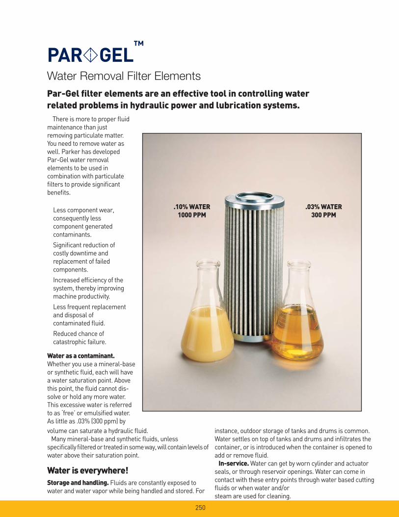
Water Removal Filter Elements
PAR GEL™
There is more to proper fl uid maintenance than just removing particulate matter.You need to remove water aswell. Parker has developedPar-Gel water removal elements to be used incombination with particulatefi lters to provide signifi cantbenefi ts.
Less component wear, consequently less component generatedcontaminants.
Signifi cant reduction of costly downtime and replacement of failed components.
Increased effi ciency of thesystem, thereby improvingmachine productivity.
Less frequent replacementand disposal of contaminated fl uid.
Reduced chance of catastrophic failure.
Water as a contaminant.Whether you use a mineral-base or synthetic fl uid, each will have a water saturation point. Above this point, the fl uid cannot dis-solve or hold any more water. This excessive water is referred to as ‘free’ or emulsifi ed water. As little as .03% (300 ppm) by
Par-Gel fi lter elements are an effective tool in controlling water related problems in hydraulic power and lubrication systems.
instance, outdoor storage of tanks and drums is common. Water settles on top of tanks and drums and infi ltrates the container, or is introduced when the container is opened to add or remove fl uid.
In-service. Water can get by worn cylinder and actuator seals, or through reservoir openings. Water can come in contact with these entry points through water based cutting fl uids or when water and/or steam are used for cleaning.
volume can saturate a hydraulic fl uid.Many mineral-base and synthetic fl uids, unless
specifi cally fi ltered or treated in some way, will contain levels of water above their saturation point.
Water is everywhere!Storage and handling. Fluids are constantly exposed to water and water vapor while being handled and stored. For
.10% WATER1000 PPM
.03% WATER300 PPM
250
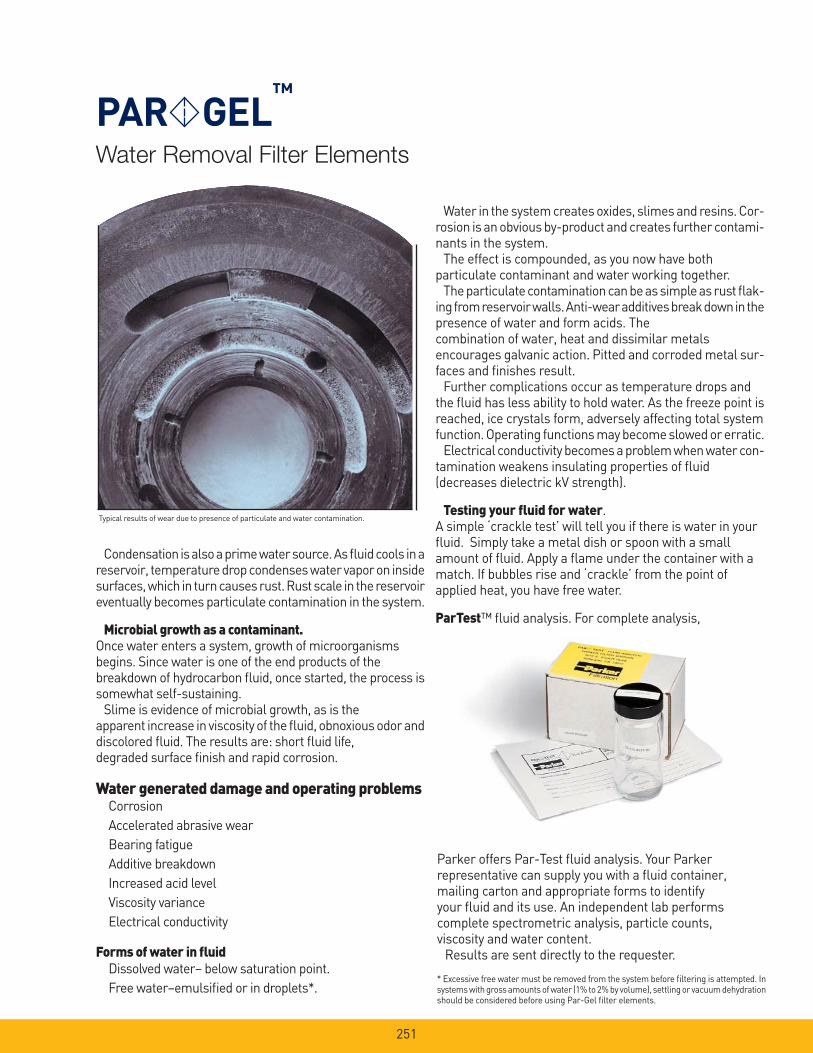
Water Removal Filter Elements
PAR GEL™
Condensation is also a prime water source. As fl uid cools in a reservoir, temperature drop condenses water vapor on inside surfaces, which in turn causes rust. Rust scale in the reservoir eventually becomes particulate contamination in the system.
Microbial growth as a contaminant. Once water enters a system, growth of microorganisms begins. Since water is one of the end products of the breakdown of hydrocarbon fl uid, once started, the process is somewhat self-sustaining.
Slime is evidence of microbial growth, as is the apparent increase in visco sity of the fl uid, obnoxious odor and discolored fl uid. The results are: short fl uid life, degraded surface fi nish and rapid corrosion.
Water generated damage and operating problems Corrosion
Accelerated abrasive wear
Bearing fatigue
Additive breakdown
Increased acid level
Viscosity variance
Electrical conductivity
Forms of water in fl uid Dissolved water– below saturation point.
Free water–emulsifi ed or in droplets*.
Water in the system creates oxides, slimes and resins. Cor-rosion is an obvious by-product and creates further contami-nants in the system.
The effect is compounded, as you now have both particulate contaminant and water working together.
The particulate contamination can be as simple as rust fl ak-ing from reservoir walls. Anti-wear additives break down in the presence of water and form acids. The combination of water, heat and dissimilar metals encourages galvanic action. Pitted and corroded metal sur-faces and fi nishes result.
Further complications occur as temperature drops and the fl uid has less ability to hold water. As the freeze point is reached, ice crystals form, adversely affecting total system function. Operating functions may become slowed or erratic.
Electrical conductivity becomes a problem when water con-tamination weakens insulating properties of fl uid (decreases dielectric kV strength).
Testing your fl uid for water.A simple ‘crackle test’ will tell you if there is water in your fl uid. Simply take a metal dish or spoon with a small amount of fl uid. Apply a fl ame under the container with a match. If bubbles rise and ‘crackle’ from the point of applied heat, you have free water.
ParTest™ fl uid analysis. For complete analysis,
Parker offers Par-Test fl uid analysis. Your Parker representative can supply you with a fl uid container, mailing carton and appropriate forms to identify your fl uid and its use. An independent lab performs complete spectrometric analysis, particle counts, viscosity and water content.
Results are sent directly to the requester.
* Excessive free water must be removed from the system before fi ltering is attempted. In systems with gross amounts of water (1% to 2% by volume), settling or vacuum dehydration should be considered before using Par-Gel fi lter elements.
Typical results of wear due to presence of particulate and water contamination.
251
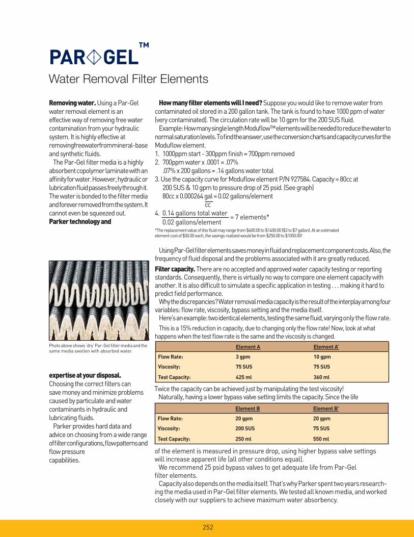
Water Removal Filter Elements
PAR GEL™
Removing water. Using a Par-Gel water removal element is an effective way of removing free water contamination from your hydraulic system. It is highly effective at removing free water from mineral-base and synthetic fl uids.
The Par-Gel fi lter media is a highly absorbent copolymer laminate with an affi nity for water. However, hydraulic or lubrication fl uid passes freely through it. The water is bonded to the fi lter media and forever removed from the system. It cannot even be squeezed out.Parker technology and
How many fi lter elements will I need? Suppose you would like to remove water from contaminated oil stored in a 200 gallon tank. The tank is found to have 1000 ppm of water (very contaminated). The circulation rate will be 10 gpm for the 200 SUS fl uid.
Example: How many single length Modufl ow™ elements will be needed to reduce the water to normal saturation levels. To fi nd the answer, use the conversion charts and capacity curves for the Modufl ow element.1. 1000ppm start - 300ppm fi nish = 700ppm removed2. 700ppm water x .0001 = .07% .07% x 200 gallons = .14 gallons water total3. Use the capacity curve for Modufl ow element P/N 927584. Capacity = 80cc at 200 SUS & 10 gpm to pressure drop of 25 psid. (See graph) 80cc x 0.000264 gal = 0.02 gallons/element cc4. 0.14 gallons total water
= 7 elements* 0.02 gallons/element*The replacement value of this fl uid may range from $600.00 to $1400.00 ($3 to $7 gallon). At an estimatedelement cost of $50.00 each, the savings realized would be from $250.00 to $1050.00!
Using Par-Gel fi lter elements saves money in fl uid and replacement component costs. Also, the frequency of fl uid disposal and the problems associated with it are greatly reduced.
Filter capacity. There are no accepted and approved water capacity testing or reporting standards. Consequently, there is virtually no way to compare one element capacity with another. It is also diffi cult to simulate a specifi c application in testing . . . making it hard to predict fi eld performance.
Why the discrepancies? Water removal media capacity is the result of the interplay among four variables: fl ow rate, viscosity, bypass setting and the media itself.
Here’s an example: two identical elements, testing the same fl uid, varying only the fl ow rate.
This is a 15% reduction in capacity, due to changing only the fl ow rate! Now, look at what
happens when the test fl ow rate is the same and the viscosity is changed.
expertise at your disposal. Choosing the correct fi lters can save money and minimize problems caused by particulate and water contaminants in hydraulic and lubricating fl uids.
Parker provides hard data and advice on choosing from a wide range of fi lter confi gurations, fl ow patterns and fl ow pressure capabilities.
Photo above shows ‘dry’ Par-Gel fi lter media and the same media swollen with absorbed water.
Element A Element A’
Flow Rate: 3 gpm 10 gpm
Viscosity: 75 SUS 75 SUS
Test Capacity: 425 ml 360 ml
Twice the capacity can be achieved just by manipulating the test viscosity!Naturally, having a lower bypass valve setting limits the capacity. Since the life
Element B Element B’
Flow Rate: 20 gpm 20 gpm
Viscosity: 200 SUS 75 SUS
Test Capacity: 250 ml 550 ml
of the element is measured in pressure drop, using higher bypass valve settings will increase apparent life (all other conditions equal).
We recommend 25 psid bypass valves to get adequate life from Par-Gel fi lter elements.
Capacity also depends on the media itself. That’s why Parker spent two years research-ing the media used in Par-Gel fi lter elements. We tested all known media, and worked closely with our suppliers to achieve maximum water absorbency.
252
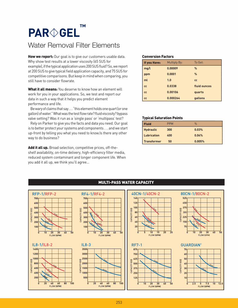
Water Removal Filter Elements
PAR GEL™
How we report: Our goal is to give our customers usable data.
Why show test results at a lower viscosity (65 SUS for
example), if the typical application uses 200 SUS fl uid? So, we report
at 200 SUS to give typical fi eld application capacity, and 75 SUS for
competitive comparisons. But keep in mind when comparing, you
still have to consider fl owrate.
What it all means: You deserve to know how an element will
work for you in your applications. So, we test and report our
data in such a way that it helps you predict element
performance and life.
Be wary of claims that say . . . “this element holds one quart (or one
gallon) of water.” What was the test fl ow rate? fl uid viscosity? bypass
valve setting? Was it run as a ‘single pass’ or ‘multipass’ test?
Rely on Parker to give you the facts and data you need. Our goal
is to better protect your systems and components . . . and we start
up-front by telling you what you need to know.Is there any other
way to do business?
Add it all up. Broad selection, competitive prices, off-the-
shelf availability, on-time delivery, high-effi ciency fi lter media,
reduced system contaminant and longer component life. When
you add it all up, we think you’ll agree...
MULTI-PASS WATER CAPACITY
If you Have: Multiply By: To Get:
mg/l 0.00009 %
ppm 0.0001 %
ml 1.0 cc
cc 0.0338 fl uid ounces
cc 0.00106 quarts
cc 0.000264 gallons
Fluid PPM %
Hydraulic 300 0.03%
Lubrication 400 0.04%
Transformer 50 0.005%
Conversion Factors
Typical Saturation Points
RFP-1/RFP-2 700
600
500
400
300
200
100
0 10 20
FLOW (GPM)
CA
PA
CIT
Y (C
C)
30 40 50
200 SUS
200 SUS
75 SUS
75 SUS
IL8-1/IL8-21400
1200
1000
800
600
400
200
0 20 40
FLOW (GPM)
CA
PA
CIT
Y (C
C)
60 80 100
200 SUS
200 SUS 75 SUS
75 SUS
40CN-1/40CN-2140
120
100
80
60
40
20
0 5 10
FLOW (GPM)
CA
PA
CIT
Y (C
C)
15 20 25
200 SUS
200 SUS 75 SUS
75 SUS
RF7-1 875
750
625
500
375
250
125
0 10 20
FLOW (GPM)
CA
PA
CIT
Y (C
C)
30 40 50
200 SUS
75 SUS
RF4-1/RF4-2700
600
500
400
300
200
100
0 10 20
FLOW (GPM)
CA
PA
CIT
Y (C
C)
30 40 50
200 SUS
20
0 S
US
75 SUS
75 SUS
IL8-33500
3000
2500
2000
1500
1000
500
0 20 40
FLOW (GPM)
CA
PA
CIT
Y (C
C)
60 80 100
75 SUS
200 SUS
80CN-1/80CN-2525
450
375
300
225
150
75
0 10 20
FLOW (GPM)
CA
PA
CIT
Y (C
C)
30 40 50
75 SUS
GUARDIAN®
70
60
50
40
30
20
10
0 2.5 5
FLOW (GPM)
CA
PA
CIT
Y (C
C)
7.5 10 12.5
200 SUS
75 SUS
200 SUS
200 SUS
200 SUS
75 SU
S
253

Water Removal Filter Elements
PAR GEL™
Ideal applications for Par-Gel fi lter elements:
Guardian® Portable Filtration System
Filter Cart
254
Filter Model Series Length Element Part Number
RFP-1
RFP-2
Single
Double
927584
927585
RF4-1
RF4-2
Single
Double
930156
928557
RF7-1
RF7-2
Single
Double
933853
932506
IL8-1
IL8-2
IL8-3
Single
Double
Triple
929103
929109
932006
40CN-1
40CN-2
Single
Double
931412
931414
80CN-1
80CN-2
Single
Double
931416
931418
Guardian® Single 932019
Parker Par-Gel water removal fi lter elements are available in these standard Parker fi lter housings:

PAR FIT™
ElementsCompetitive Interchanges
255
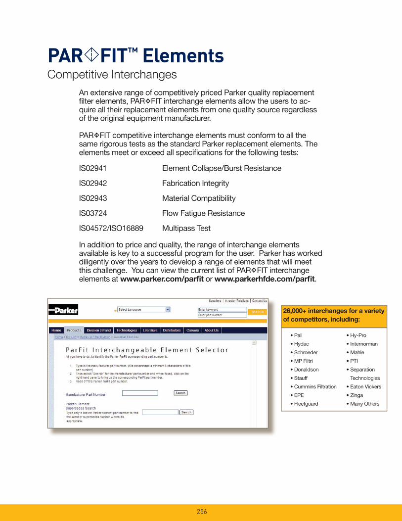
An extensive range of competitively priced Parker quality replacement fi lter elements, PAR FIT interchange elements allow the users to ac-quire all their replacement elements from one quality source regardless of the original equipment manufacturer.
PAR FIT competitive interchange elements must conform to all the same rigorous tests as the standard Parker replacement elements. The elements meet or exceed all specifi cations for the following tests:
IS02941 Element Collapse/Burst Resistance
IS02942 Fabrication Integrity
IS02943 Material Compatibility
IS03724 Flow Fatigue Resistance
IS04572/ISO16889 Multipass Test
In addition to price and quality, the range of interchange elements available is key to a successful program for the user. Parker has worked diligently over the years to develop a range of elements that will meet this challenge. You can view the current list of PAR FIT interchange elements at www.parker.com/parfi t or www.parkerhfde.com/parfi t.
PAR FIT™ ElementsCompetitive Interchanges
• Pall
• Hydac
• Schroeder
• MP Filtri
• Donaldson
• Stauff
• Cummins Filtration
• EPE
• Fleetguard
• Hy-Pro
• Internorman
• Mahle
• PTI
• Separation
Technologies
• Eaton Vickers
• Zinga
• Many Others
26,000+ interchanges for a variety
of competitors, including:
256
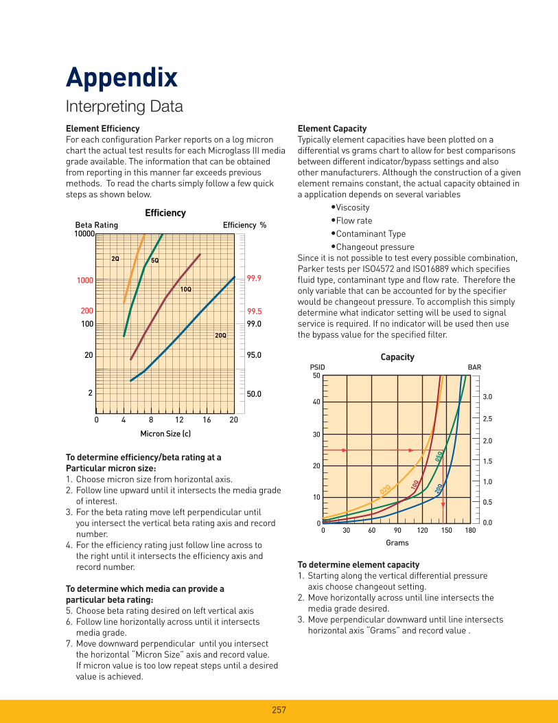
257
Interpreting Data
Appendix
Element Effi ciency
For each confi guration Parker reports on a log micron
chart the actual test results for each Microglass III media
grade available. The information that can be obtained
from reporting in this manner far exceeds previous
methods. To read the charts simply follow a few quick
steps as shown below.
To determine effi ciency/beta rating at a
Particular micron size:
1. Choose micron size from horizontal axis.
2. Follow line upward until it intersects the media grade
of interest.
3. For the beta rating move left perpendicular until
you intersect the vertical beta rating axis and record
number.
4. For the effi ciency rating just follow line across to
the right until it intersects the effi ciency axis and
record number.
To determine which media can provide a
particular beta rating:
5. Choose beta rating desired on left vertical axis
6. Follow line horizontally across until it intersects
media grade.
7. Move downward perpendicular until you intersect
the horizontal “Micron Size” axis and record value.
If micron value is too low repeat steps until a desired
value is achieved.
Efficiency %Efficiency
Beta Rating
1000
10000
99.9
99.599.0100
200
20
2 50.0
95.0
Micron Size (c)
2Q
10Q
20Q
2Q
10Q
20Q
2Q
10Q
20Q
5Q5Q
0 4 8 12 16 20
CapacityBAR
Grams
0 30 60 90 120 150 180
50
40
30
20
10
0
3.0
2.5
2.0
1.5
1.0
0.5
0.0
PSID
02Q
05Q
10Q
20Q
Element Capacity
Typically element capacities have been plotted on a
differential vs grams chart to allow for best comparisons
between different indicator/bypass settings and also
other manufacturers. Although the construction of a given
element remains constant, the actual capacity obtained in
a application depends on several variables
•Viscosity
•Flow rate
•Contaminant Type
•Changeout pressure
Since it is not possible to test every possible combination,
Parker tests per ISO4572 and ISO16889 which specifi es
fl uid type, contaminant type and fl ow rate. Therefore the
only variable that can be accounted for by the specifi er
would be changeout pressure. To accomplish this simply
determine what indicator setting will be used to signal
service is required. If no indicator will be used then use
the bypass value for the specifi ed fi lter.
To determine element capacity
1. Starting along the vertical differential pressure
axis choose changeout setting.
2. Move horizontally across until line intersects the
media grade desired.
3. Move perpendicular downward until line intersects
horizontal axis “Grams” and record value .

258
Interpreting Data
Appendix
Flow vs Pressure Loss
All performance curves are reported at a standard
viscosity of 150 SUS (30 cSt) with element pressure
curves independent of the housing. The purpose of
reporting individually is to allow for adjustment to other
operating viscosities. To adjust for a operating viscos-
ity other then 150 SUS (30 cSt) please use the correction
formula below.
High Collapse Elements
In most cases, fi lter assemblies are equipped with an
internal bypass valve to limit the differential pressure
across the element. In some critical applications it may
be necessary to equip the fi lter with a “no bypass” valve
which forces all fl uid fl ow to pass through the element.
When a fi lter is equipped with a “no bypass” valve, the
element must be able to withstand much higher
differential pressures in the event it is not serviced when
indicated. Parker high collapse elements are able to
withstand 2000 psid (“H” option) or 3000 psid (“X” option)
due to their special construction. The high collapse
elements are rated for the same effi ciencies as the
standard elements but also have a higher clean
pressure loss.
The increase in pressure loss from standard collapse
“Q” elements to high collapse “Q” elements varies from
media grade and series. To insure adequate element
life, a correction factor should be applied to the standard
pressure loss curves. Below are the factors that should
be applied to the standard element performance curves
shown in this catalog. The pressure loss of “H” option
elements (2000 psid collapse) may increase as much as
40% over the standard, and the “X” option 3000 psid
collapse) as much as 90%.
High Collapse Correction Factors
“QH” Elements (2000 psid) = 1.4 times reported loss
“QX” Elements (3000 psid) = 1.9 times reported loss
PSID Element = PSID from catalog x x
PSID Housing = PSID from catalog x
PSID Assembly = PSID Element + PSID Housing
New Viscosity
150
New Specifi c Gravity
.90
New Specifi c Gravity
.90
Viscosity Correction Formula
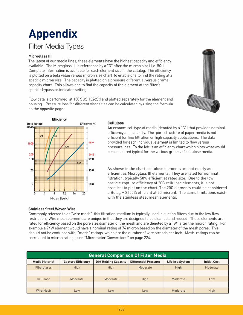
259
Microglass III
The latest of our media lines, these elements have the highest capacity and effi ciency
available. The Microglass III is referenced by a “Q” after the micron size ( i.e. 5Q ).
Complete information is available for each element size in the catalog. The effi ciency
is plotted on a beta value versus micron size chart to enable one to fi nd the rating at a
specifi c micron size. The capacity is plotted on a pressure differential versus grams
capacity chart. This allows one to fi nd the capacity of the element at the fi lter’s
specifi c bypass or indicator setting.
Flow data is performed at 150 SUS (32cSt) and plotted separately for the element and
housing . Pressure loss for different viscosities can be calculated by using the formula
on the opposite page.
Cellulose
An economical type of media (denoted by a “C”) that provides nominal
effi ciency and capacity. The pore structure of paper media is not
effi cient for fi ne fi ltration or high capacity applications. The data
provided for each individual element is limited to fl ow versus
pressure loss. To the left is an effi ciency chart which plots what would
be considered typical for the various grades of cellulose media.
Stainless Steel Woven Wire
Commonly referred to as “wire mesh” this fi ltration medium is typically used in suction fi lters due to the low fl ow
restriction. Wire mesh elements are unique in that they are designed to be cleaned and reused. These elements are
rated for effi ciency based on the pore size diameter of the mesh and are denoted by a “W” after the micron rating. For
example a 74W element would have a nominal rating of 74 micron based on the diameter of the mesh pores. This
should not be confused with “mesh” ratings which are the number of wire strands per inch. Mesh ratings can be
correlated to micron ratings, see “Micrometer Conversions” on page 224.
As shown in the chart, cellulose elements are not nearly as
effi cient as Microglass III elements. They are rated for nominal
fi ltration, typically 50% effi cient at rated size. Due to the low
particle capture effi ciency of 20C cellulose elements, it is not
practical to plot on the chart. The 20C elements could be considered
a Beta20
= 2 (50% effi cient at 20 micron). The same limitations exist
with the stainless steel mesh elements.
Efficiency %Efficiency
Beta Rating
1000
10000
99.9
99.599.0100
200
20
2 50.0
95.0
Micron Size (c)
2Q
10Q
20Q
2Q
10Q
20Q
2Q
10Q
20Q
5Q5Q
0 4 8 12 16 20
Filter Media Types
Appendix
General Comparison Of Filter Media
Media Material Capture Effi ciency Dirt Holding Capacity Differential Pressure Life In a System Initial Cost
FIberglasss High High Moderate High Moderate
Cellulose Moderate Moderate High Moderate Low
Wire Mesh Low Low Low Moderate High
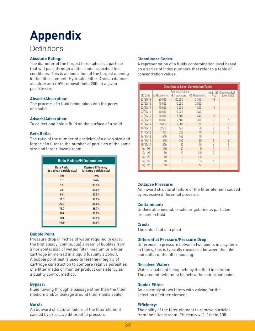
260
Defi nitions
Appendix
Absolute Rating:
The diameter of the largest hard spherical particle
that will pass through a fi lter under specifi ed test
conditions. This is an indication of the largest opening
in the fi lter element. Hydraulic Filter Division defi nes
absolute as 99.5% removal (beta 200) at a given
particle size.
Absorb/Absorption:
The process of a fl uid being taken into the pores
of a solid.
Adsorb/Adsorption:
To collect and hold a fl uid on the surface of a solid.
Beta Ratio:
The ratio of the number of particles of a given size and
larger of a fi lter to the number of particles of the same
size and larger downstream.
Bubble Point:
Pressure drop in inches of water required to expel
the fi rst steady (continuous) stream of bubbles from
a horizontal disc of wetted fi lter medium or a fi lter
cartridge immersed in a liquid (usually alcohol).
A bubble point test is used to test the integrity of
cartridge construction to compare relative porosities
of a fi lter media or monitor product consistency as
a quality control method.
Bypass:
Fluid fl owing through a passage other than the fi lter
medium and/or leakage around fi lter media seals.
Burst:
An outward structural failure of the fi lter element
caused by excessive differential pressure.
Cleanliness Codes:
A representation of a fl uids contamination level based
on a series of index numbers that refer to a table of
concentration values.
Collapse Pressure:
An inward structural failure of the fi lter element caused
by excessive differential pressure.
Contaminant:
Undesirable insoluble solid or gelatinous particles
present in fl uid.
Crest:
The outer fold of a pleat.
Differential Pressure/Pressure Drop:
Difference in pressure between two points in a system.
In fi lters, this is typically measured between the inlet
and outlet of the fi lter housing.
Dissolved Water:
Water capable of being held by the fl uid in solution.
The amount held must be below the saturation point.
Duplex Filter:
An assembly of two fi lters with valving for the
selection of either element.
Effi ciency:
The ability of the fi lter element to remove particles
from the fi lter stream. Effi ciency = (1-1/beta)100.
Beta Ratios/EfficienciesBeta Ratio Capture Efficiency
(at a given particle size) (at same particle size)
1.01 1.0%
1.1 9.0%
1.5 33.3%
2.0 50.0%
5.0 80.0%
10.0 90.0%
20.0 95.0%
75.0 98.7%
100 99.0%
200 99.5%
1000 99.9%

261
Nominal Rating:
Micron size removed at a given effi ciency under a
manufacturer’s defi ned test condition. An arbitrary
term assigned by manufacturers which varies and
has therefore depreciated in value.
Pinched Pleat:
A pleat closed off by excessive differential pressure
or crowding, thus reducing the effective area of the
fi lter element.
Pleats:
a series of folds in the fi lter medium usually of
uniform height and spacing designed to maximize
effective area.
Pressure Line Filter:
A fi lter located in a line conducting working fl uid to
a working device or devices.
Return Line Filter:
A fi lter located in the line which is conducting working
fl uid form working devices to a reservoir.
Root:
The inside fold of a pleat.
Suction Filter:
A fi lter located in the intake line of a pump where the
fl uid is below atmospheric pressure.
T-Type Filter:
A fi lter in which the inlet and outlet port axes are in a
straight line, and the fi lter element axis is
perpendicular to this line.
Varnish:
Materials generated by the hydraulic fl uid due to
oxidation, thermal instability, or other reactions. These
materials are insoluble in the hydraulic fl uid and are
generally found as brownish deposits in the work
surfaces.
Y-Type Filter:
A fi lter in which the inlet and outlet port axes are in a
straight line, and the fi lter element is at an acute angle
to this line.
Defi nitions
Appendix
Effl uent:
The fl uid that has passed through the fi lter.
Filter Medium:
The permeable material used for a fi lter that separates
particles from a fl uid passing through it.
Flow Fatigue:
The ability of a fi lter element to withstand structural
failure of the fi lter medium due to fl exing of the pleats
caused by cyclic differential pressure.
Free Water:
Water droplets or globules in a system that tend to
accumulate at the bottom of a system’s fl uid because it
exceeds the solubility of the fl uid.
Infl uent:
Fluid entering the inlet of a fi lter.
In-Line Filter:
A fi lter in which the inlet, outlet and element are in a
straight axis.
L-Type Filter:
A fi lter in which the inlet and outlet port axis are at
right angles, and the fi lter element axis is parallel to
either port axis.
Laminar Flow:
Flow rate at which liquid is in a nonturbulent state
(10ft/sec) and should not exceeded to maintain
fi ltration integrity and consistency.
Media Migration:
Contamination of the effl uent by fi bers or other
material of which the fi lter is constructed.
Micron:
A unit of length. Correct term is micrometer (µm),
which is .000039 inch. Human eye can see a
40 micrometer particle.
Neutralization Number:
A measure of the acidity or basicity of a fl uid, this
includes organic an inorganic acids or bases, or
combination thereof.
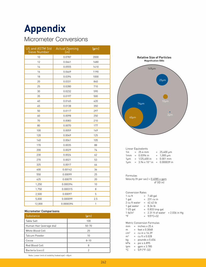
262
Micrometer Conversions
Appendix
Note: Lower limit of visibility (naked eye)—40µm
Relative Size of ParticlesMagnifi cation 500x
Linear Equivalents
1in = 25.4 mm = 25,400 µm
1mm = 0.0394 in = 1,000 µm
1µm = 1/25,400 in = 0.001 mm
1µm = 3.94 x 10⁻⁵ in = 0.000039 in
Formulas
Velocity (ft per sec) = 0.4085 x gpm
d2 (ID in)
Conversion Rates
1 cu ft = 7.48 gal
1 gal = 231 cu in
2 cu ft water = 62.42 lb
1 gal water = 8.34 lb
1 US gal = 0.833 lmp gal
1 lb/in2 = 2.31 ft of water = 2.036 in Hg
°F = 9/5°C+32
Metric Conversion Formulas
mm = inches x 25.4
m = feet x 0.3048
cm3 = cu in x 16.39
m3 = cu ft x 0.028
kg = pounds x 0.454
kPa = psi x 6.895
lpm = gpm x 3.785
°C = 5/9 (°F-32)
Micrometer Comparisons
74µm
40µm2µm
149µm
10µm
25µm
US and ASTM StdSieve Number
Actual Opening(in)
(µm)
10 0.0787 2000
12 0.0661 1680
14 0.0555 1410
16 0.0469 1190
18 0.0394 1000
20 0.0331 840
25 0.0280 710
30 0.0232 590
35 0.0197 500
40 0.0165 420
45 0.0138 350
50 0.0117 297
60 0.0098 250
70 0.0083 210
80 0.0070 177
100 0.0059 149
120 0.0049 125
140 0.0041 105
170 0.0035 88
200 0.0029 74
230 0.0024 62
270 0.0021 53
325 0.0017 44
400 0.00142 36
550 0.00099 25
625 0.00079 20
1,250 0.000394 10
1,750 0.000315 8
2,500 0.00097 5
5,000 0.000099 2.5
12,000 0.0000394 1
Substance (µm)
Table Salt 100
Human Hair (average dia) 50-70
White Blood Cell 25
Talcum Powder 10
Cocoa 8-10
Red Blood Cell 8
Bacteria (cocci) 2
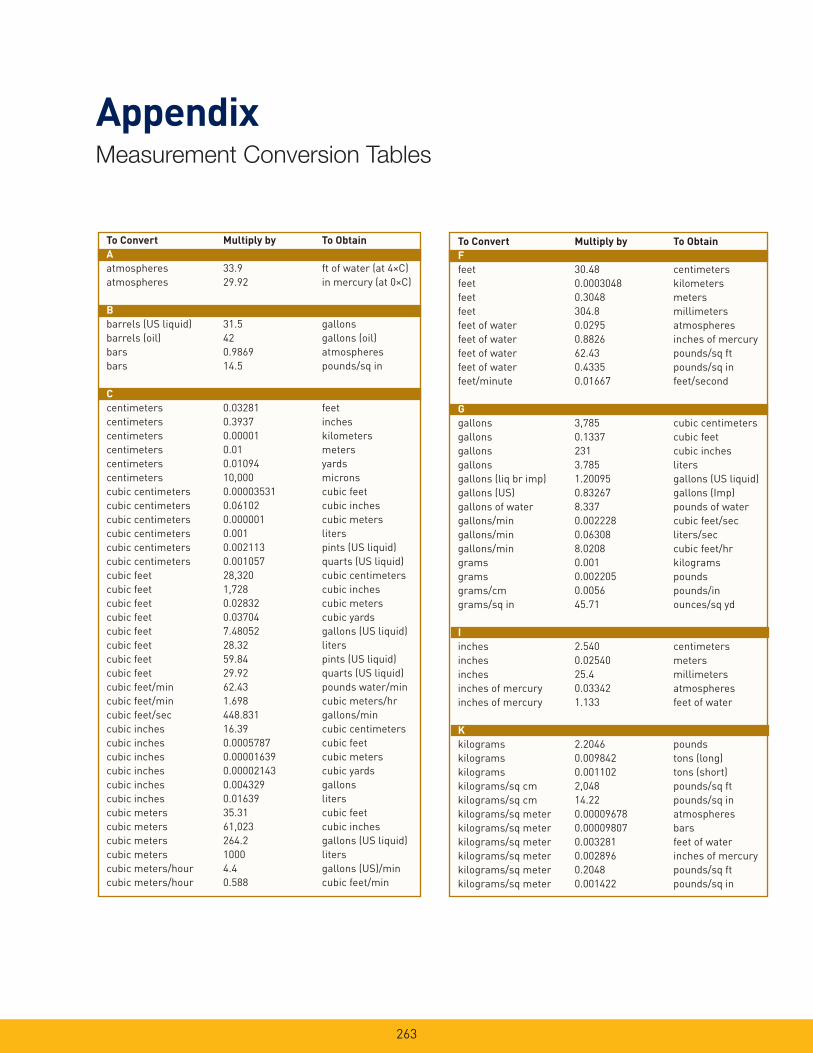
263
Measurement Conversion Tables
Appendix
To Convert Multiply by To Obtain
A
atmospheres 33.9 ft of water (at 4×C)
atmospheres 29.92 in mercury (at 0×C)
B
barrels (US liquid) 31.5 gallons
barrels (oil) 42 gallons (oil)
bars 0.9869 atmospheres
bars 14.5 pounds/sq in
C
centimeters 0.03281 feet
centimeters 0.3937 inches
centimeters 0.00001 kilometers
centimeters 0.01 meters
centimeters 0.01094 yards
centimeters 10,000 microns
cubic centimeters 0.00003531 cubic feet
cubic centimeters 0.06102 cubic inches
cubic centimeters 0.000001 cubic meters
cubic centimeters 0.001 liters
cubic centimeters 0.002113 pints (US liquid)
cubic centimeters 0.001057 quarts (US liquid)
cubic feet 28,320 cubic centimeters
cubic feet 1,728 cubic inches
cubic feet 0.02832 cubic meters
cubic feet 0.03704 cubic yards
cubic feet 7.48052 gallons (US liquid)
cubic feet 28.32 liters
cubic feet 59.84 pints (US liquid)
cubic feet 29.92 quarts (US liquid)
cubic feet/min 62.43 pounds water/min
cubic feet/min 1.698 cubic meters/hr
cubic feet/sec 448.831 gallons/min
cubic inches 16.39 cubic centimeters
cubic inches 0.0005787 cubic feet
cubic inches 0.00001639 cubic meters
cubic inches 0.00002143 cubic yards
cubic inches 0.004329 gallons
cubic inches 0.01639 liters
cubic meters 35.31 cubic feet
cubic meters 61,023 cubic inches
cubic meters 264.2 gallons (US liquid)
cubic meters 1000 liters
cubic meters/hour 4.4 gallons (US)/min
cubic meters/hour 0.588 cubic feet/min
To Convert Multiply by To Obtain
F
feet 30.48 centimeters
feet 0.0003048 kilometers
feet 0.3048 meters
feet 304.8 millimeters
feet of water 0.0295 atmospheres
feet of water 0.8826 inches of mercury
feet of water 62.43 pounds/sq ft
feet of water 0.4335 pounds/sq in
feet/minute 0.01667 feet/second
G
gallons 3,785 cubic centimeters
gallons 0.1337 cubic feet
gallons 231 cubic inches
gallons 3.785 liters
gallons (liq br imp) 1.20095 gallons (US liquid)
gallons (US) 0.83267 gallons (Imp)
gallons of water 8.337 pounds of water
gallons/min 0.002228 cubic feet/sec
gallons/min 0.06308 liters/sec
gallons/min 8.0208 cubic feet/hr
grams 0.001 kilograms
grams 0.002205 pounds
grams/cm 0.0056 pounds/in
grams/sq in 45.71 ounces/sq yd
I
inches 2.540 centimeters
inches 0.02540 meters
inches 25.4 millimeters
inches of mercury 0.03342 atmospheres
inches of mercury 1.133 feet of water
K
kilograms 2.2046 pounds
kilograms 0.009842 tons (long)
kilograms 0.001102 tons (short)
kilograms/sq cm 2,048 pounds/sq ft
kilograms/sq cm 14.22 pounds/sq in
kilograms/sq meter 0.00009678 atmospheres
kilograms/sq meter 0.00009807 bars
kilograms/sq meter 0.003281 feet of water
kilograms/sq meter 0.002896 inches of mercury
kilograms/sq meter 0.2048 pounds/sq ft
kilograms/sq meter 0.001422 pounds/sq in

264
Measurement Conversion Tables
Appendix
To Convert Multiply by To Obtain
L
liters 0.2642 gallons (US liquid)
liters 2.113 pints (US liquid)
liters 1.057 quarts (US liquid)
liters/min 0.0005886 cubic ft/sec
liters/min 0.004403 gallons/sec
liters/hour 0.004403 gallons (US)/min
M
meters 3.281 feet
meters 39.37 inches
meters 0.001 kilometers
meters/min 3.281 feet/min
meters/min 0.05468 feet/sec
microns 0.000001 meters
mils 0.00254 centimeters
mils 0.000083333 feet
mils 0.001 inches
mils 0.0000000254 kilometers
O
ounces 28.349 grams
ounces 0.0625 pounds
ounces (fl uid) 1.805 cubic inches
ounces (fl uid) 0.02957 liters
ounces/sq in 0.0625 pounds/sq in
ounces/sq yard 20.83 pounds/3000 sq ft
P
pints (liquid) 0.125 gallons
pints (liquid) 0.4732 liters
pints (liquid) 0.5 quarts (liquid)
pounds 453.59 grams
pounds 16 ounces
pounds/sq ft 0.0004725 atmospheres
pounds/sq ft 0.01602 feet of water
pounds/sq ft 0.01414 inches of mercury
pounds/sq in 0.06804 atmospheres
pounds/sq in 2.307 feet of water
pounds/sq in 2.036 inches of mercury
pounds/sq in 0.0145 kilo pascals (kPa)
pounds/sq in 27.684 inches water column
pounds/3000 sq in 0.048 ounces/sq yard
To Convert Multiply by To Obtain
Q
quarts (liquid) 0.03342 cubic feet
quarts (liquid) 57.75 cubic inches
quarts (liquid) 0.0009464 cubic meters
quarts (liquid) 0.25 gallons
quarts (liquid) 0.9463 liters
S
square centimeters 0.001076 square feet
square centimeters 0.1550 square inches
square centimeters 0.0001 square meters
square feet 144 square inches
square feet 0.0929 square meters
square inches 0.006944 square feet
square inches 0.0007716 square yards
square meters 10.76 square feet
square meters 155 square inches
square meters 1.196 square yards
square yards 9 square feet
square yards 1,296 square inches
square yards 0.8361 square meters
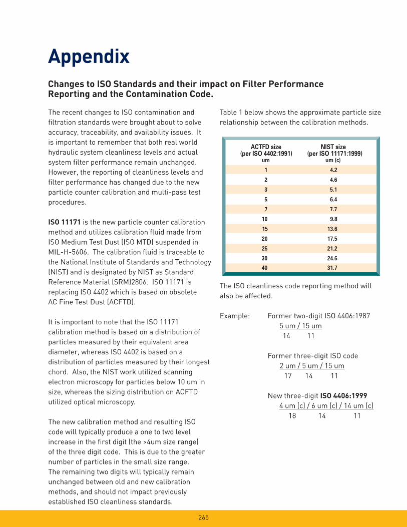
265
AppendixChanges to ISO Standards and their impact on Filter PerformanceReporting and the Contamination Code.
The recent changes to ISO contamination and
fi ltration standards were brought about to solve
accuracy, traceability, and availability issues. It
is important to remember that both real world
hydraulic system cleanliness levels and actual
system fi lter performance remain unchanged.
However, the reporting of cleanliness levels and
fi lter performance has changed due to the new
particle counter calibration and multi-pass test
procedures.
ISO 11171 is the new particle counter calibration
method and utilizes calibration fl uid made from
ISO Medium Test Dust (ISO MTD) suspended in
MIL-H-5606. The calibration fl uid is traceable to
the National Institute of Standards and Technology
(NIST) and is designated by NIST as Standard
Reference Material (SRM)2806. ISO 11171 is
replacing ISO 4402 which is based on obsolete
AC Fine Test Dust (ACFTD).
It is important to note that the ISO 11171
calibration method is based on a distribution of
particles measured by their equivalent area
diameter, whereas ISO 4402 is based on a
distribution of particles measured by their longest
chord. Also, the NIST work utilized scanning
electron microscopy for particles below 10 um in
size, whereas the sizing distribution on ACFTD
utilized optical microscopy.
The new calibration method and resulting ISO
code will typically produce a one to two level
increase in the fi rst digit (the >4um size range)
of the three digit code. This is due to the greater
number of particles in the small size range.
The remaining two digits will typically remain
unchanged between old and new calibration
methods, and should not impact previously
established ISO cleanliness standards.
ACTFD size NIST size(per ISO 4402:1991) (per ISO 11171:1999)
um um (c)
1 4.2
2 4.6
3 5.1
5 6.4
7 7.7
10 9.8
15 13.6
20 17.5
25 21.2
30 24.6
40 31.7
Table 1 below shows the approximate particle size
relationship between the calibration methods.
The ISO cleanliness code reporting method will
also be affected.
Example: Former two-digit ISO 4406:1987
5 um / 15 um
14 11
Former three-digit ISO code
2 um / 5 um / 15 um
17 14 11
New three-digit ISO 4406:1999
4 um (c) / 6 um (c) / 14 um (c)
18 14 11

266
AppendixChanges to ISO Standards and their impact on Filter PerformanceReporting and the Contamination Code, continued.
ISO 16889 is the new multi-pass test standard for
measuring fi lter performance and utilizes ISO MTD
as the contaminant challenge. This standard is
replacing ISO 4572 which utilized ACFTD. See
the following graphs below for fi ltration beta ratio
comparisons on our 2Q, 5Q, 10Q, and 20Q
Microglass III media. The graphs refl ect
multi-pass test results using ISO 4572 with ACFTD
and the revised ISO 16889 using ISO MTD.
FILTRATION RATIOS FOR 2Q MEDIA
1
10
100
1000
10000
0 1 2 3 4 5 6 7
FILT
RAT
ION
RAT
IO(B
ETA)
200 ISO 16889ISO 16889
ISO 4572ISO 4572
FILTRATION RATIOS FOR 5Q MEDIA
1
10
100
1000
10000
PARTICLE SIZE um or um(c)
FILT
RAT
ION
RAT
IO(B
ETA)
200
0 1 2 3 4 5 6 7 8 9 10
ISO 4572
ISO 16889
ISO 4572
ISO 16889
FILTRATION RATIOS FOR 10Q MEDIA
1
10
100
1000
10000
PARTICLE SIZE um or um(c)
FILT
RAT
ION
RAT
IO(B
ETA) 200
0 2 4 6 8 10 12 14 16
ISO 16889ISO 16889ISO 4572ISO 4572
FILTRATION RATIOS FOR 20Q MEDIA
1
10
100
1000
10000
PARTICLE SIZE um or um(c)
FILT
RAT
ION
RAT
IO(B
ETA) 200
0 5 10 15 20 25 30
ISO 16889
ISO 4572
ISO 16889
ISO 4572
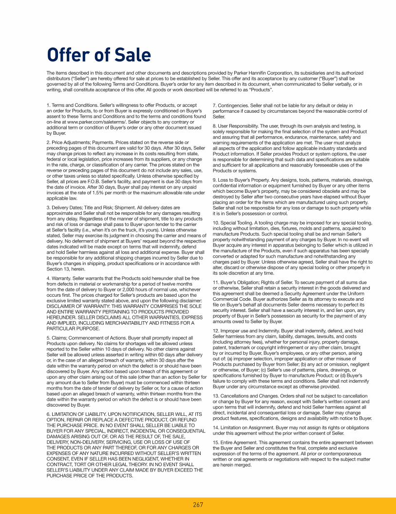
The items described in this document and other documents and descriptions provided by Parker Hannifi n Corporation, its subsidiaries and its authorized distributors (“Seller”) are hereby offered for sale at prices to be established by Seller. This offer and its acceptance by any customer (“Buyer”) shall be governed by all of the following Terms and Conditions. Buyer’s order for any item described in its document, when communicated to Seller verbally, or in writing, shall constitute acceptance of this offer. All goods or work described will be referred to as “Products”.
1. Terms and Conditions. Seller’s willingness to offer Products, or accept an order for Products, to or from Buyer is expressly conditioned on Buyer’s assent to these Terms and Conditions and to the terms and conditions found on-line at www.parker.com/saleterms/. Seller objects to any contrary or additional term or condition of Buyer’s order or any other document issued by Buyer.
2. Price Adjustments; Payments. Prices stated on the reverse side or preceding pages of this document are valid for 30 days. After 30 days, Seller may change prices to refl ect any increase in its costs resulting from state, federal or local legislation, price increases from its suppliers, or any change in the rate, charge, or classifi cation of any carrier. The prices stated on the reverse or preceding pages of this document do not include any sales, use, or other taxes unless so stated specifi cally. Unless otherwise specifi ed by Seller, all prices are F.O.B. Seller’s facility, and payment is due 30 days from the date of invoice. After 30 days, Buyer shall pay interest on any unpaid invoices at the rate of 1.5% per month or the maximum allowable rate under applicable law.
3. Delivery Dates; Title and Risk; Shipment. All delivery dates are approximate and Seller shall not be responsible for any damages resulting from any delay. Regardless of the manner of shipment, title to any products and risk of loss or damage shall pass to Buyer upon tender to the carrier at Seller’s facility (i.e., when it’s on the truck, it’s yours). Unless otherwise stated, Seller may exercise its judgment in choosing the carrier and means of delivery. No deferment of shipment at Buyers’ request beyond the respective dates indicated will be made except on terms that will indemnify, defend and hold Seller harmless against all loss and additional expense. Buyer shall be responsible for any additional shipping charges incurred by Seller due to Buyer’s changes in shipping, product specifi cations or in accordance with Section 13, herein.
4. Warranty. Seller warrants that the Products sold hereunder shall be free from defects in material or workmanship for a period of twelve months from the date of delivery to Buyer or 2,000 hours of normal use, whichever occurs fi rst. The prices charged for Seller’s products are based upon the exclusive limited warranty stated above, and upon the following disclaimer: DISCLAIMER OF WARRANTY: THIS WARRANTY COMPRISES THE SOLE AND ENTIRE WARRANTY PERTAINING TO PRODUCTS PROVIDED HEREUNDER. SELLER DISCLAIMS ALL OTHER WARRANTIES, EXPRESS AND IMPLIED, INCLUDING MERCHANTABILITY AND FITNESS FOR A PARTICULAR PURPOSE.
5. Claims; Commencement of Actions. Buyer shall promptly inspect all Products upon delivery. No claims for shortages will be allowed unless reported to the Seller within 10 days of delivery. No other claims against Seller will be allowed unless asserted in writing within 60 days after delivery or, in the case of an alleged breach of warranty, within 30 days after the date within the warranty period on which the defect is or should have been discovered by Buyer. Any action based upon breach of this agreement or upon any other claim arising out of this sale (other than an action by Seller for any amount due to Seller from Buyer) must be commenced within thirteen months from the date of tender of delivery by Seller or, for a cause of action based upon an alleged breach of warranty, within thirteen months from the date within the warranty period on which the defect is or should have been discovered by Buyer.
6. LIMITATION OF LIABILITY. UPON NOTIFICATION, SELLER WILL, AT ITS OPTION, REPAIR OR REPLACE A DEFECTIVE PRODUCT, OR REFUND THE PURCHASE PRICE. IN NO EVENT SHALL SELLER BE LIABLE TO BUYER FOR ANY SPECIAL, INDIRECT, INCIDENTAL OR CONSEQUENTIAL DAMAGES ARISING OUT OF, OR AS THE RESULT OF, THE SALE, DELIVERY, NON-DELIVERY, SERVICING, USE OR LOSS OF USE OF THE PRODUCTS OR ANY PART THEREOF, OR FOR ANY CHARGES OR EXPENSES OF ANY NATURE INCURRED WITHOUT SELLER’S WRITTEN CONSENT, EVEN IF SELLER HAS BEEN NEGLIGENT, WHETHER IN CONTRACT, TORT OR OTHER LEGAL THEORY. IN NO EVENT SHALL SELLER’S LIABILITY UNDER ANY CLAIM MADE BY BUYER EXCEED THE PURCHASE PRICE OF THE PRODUCTS.
7. Contingencies. Seller shall not be liable for any default or delay in performance if caused by circumstances beyond the reasonable control of Seller.
8. User Responsibility. The user, through its own analysis and testing, is solely responsible for making the fi nal selection of the system and Product and assuring that all performance, endurance, maintenance, safety and warning requirements of the application are met. The user must analyze all aspects of the application and follow applicable industry standards and Product information. If Seller provides Product or system options, the user is responsible for determining that such data and specifi cations are suitable and suffi cient for all applications and reasonably foreseeable uses of the Products or systems.
9. Loss to Buyer’s Property. Any designs, tools, patterns, materials, drawings, confi dential information or equipment furnished by Buyer or any other items which become Buyer’s property, may be considered obsolete and may be destroyed by Seller after two consecutive years have elapsed without Buyer placing an order for the items which are manufactured using such property. Seller shall not be responsible for any loss or damage to such property while it is in Seller’s possession or control.
10. Special Tooling. A tooling charge may be imposed for any special tooling, including without limitation, dies, fi xtures, molds and patterns, acquired to manufacture Products. Such special tooling shall be and remain Seller’s property notwithstanding payment of any charges by Buyer. In no event will Buyer acquire any interest in apparatus belonging to Seller which is utilized in the manufacture of the Products, even if such apparatus has been specially converted or adapted for such manufacture and notwithstanding any charges paid by Buyer. Unless otherwise agreed, Seller shall have the right to alter, discard or otherwise dispose of any special tooling or other property in its sole discretion at any time.
11. Buyer’s Obligation; Rights of Seller. To secure payment of all sums due or otherwise, Seller shall retain a security interest in the goods delivered and this agreement shall be deemed a Security Agreement under the Uniform Commercial Code. Buyer authorizes Seller as its attorney to execute and fi le on Buyer’s behalf all documents Seller deems necessary to perfect its security interest. Seller shall have a security interest in, and lien upon, any property of Buyer in Seller’s possession as security for the payment of any amounts owed to Seller by Buyer.
12. Improper use and Indemnity. Buyer shall indemnify, defend, and hold Seller harmless from any claim, liability, damages, lawsuits, and costs (including attorney fees), whether for personal injury, property damage, patent, trademark or copyright infringement or any other claim, brought by or incurred by Buyer, Buyer’s employees, or any other person, arising out of: (a) improper selection, improper application or other misuse of Products purchased by Buyer from Seller; (b) any act or omission, negligent or otherwise, of Buyer; (c) Seller’s use of patterns, plans, drawings, or specifi cations furnished by Buyer to manufacture Product; or (d) Buyer’s failure to comply with these terms and conditions. Seller shall not indemnify Buyer under any circumstance except as otherwise provided.
13. Cancellations and Changes. Orders shall not be subject to cancellation or change by Buyer for any reason, except with Seller’s written consent and upon terms that will indemnify, defend and hold Seller harmless against all direct, incidental and consequential loss or damage. Seller may change product features, specifi cations, designs and availability with notice to Buyer.
14. Limitation on Assignment. Buyer may not assign its rights or obligations under this agreement without the prior written consent of Seller.
15. Entire Agreement. This agreement contains the entire agreement between the Buyer and Seller and constitutes the fi nal, complete and exclusive expression of the terms of the agreement. All prior or contemporaneous written or oral agreements or negotiations with respect to the subject matter are herein merged.
Offer of Sale
267

Offer of SaleThe items described in this document and other documents and descriptions provided by Parker Hannifi n Corporation, its subsidiaries and its authorized distributors (“Seller”) are hereby offered for sale at prices to be established by Seller. This offer and its acceptance by any customer (“Buyer”) shall be governed by all of the following Terms and Conditions. Buyer’s order for any item described in its document, when communicated to Seller verbally, or in writing, shall constitute acceptance of this offer. All goods or work described will be referred to as “Products”.
16. Waiver and Severability. Failure to enforce any provision of this agreement will not waive that provision nor will any such failure prejudice Seller’s right to enforce that provision in the future. Invalidation of any provision of this agreement by legislation or other rule of law shall not invalidate any other provision herein. The remaining provisions of this agreement will remain in full force and effect.
17. Termination. This agreement may be terminated by Seller for any reason and at any time by giving Buyer thirty (30) days written notice of termination. In addition, Seller may by written notice immediately terminate this agreement for the following: (a) Buyer commits a breach of any provision of this agreement (b) the appointment of a trustee, receiver or custodian for all or any part of Buyer’s property (c) the fi ling of a petition for relief in bankruptcy of the other Party on its own behalf, or by a third party (d) an assignment for the benefi t of creditors, or (e) the dissolution or liquidation of the Buyer.
18. Governing Law. This agreement and the sale and delivery of all Products hereunder shall be deemed to have taken place in and shall be governed and construed in accordance with the laws of the State of Ohio, as applicable to contracts executed and wholly performed therein and without regard to confl icts of laws principles. Buyer irrevocably agrees and consents to the exclusive jurisdiction and venue of the courts of Cuyahoga County, Ohio with respect to any dispute, controversy or claim arising out of or relating to this agreement. Disputes between the parties shall not be settled by arbitration unless, after a dispute has arisen, both parties expressly agree in writing to arbitrate the dispute.
19. Indemnity for Infringement of Intellectual Property Rights. Seller shall have no liability for infringement of any patents, trademarks, copyrights, trade dress, trade secrets or similar rights except as provided in this Section. Seller will defend and indemnify Buyer against allegations of infringement of U.S. patents, U.S. trademarks, copyrights, trade dress and trade secrets (“Intellectual Property Rights”). Seller will defend at its expense and will pay the cost of any settlement or damages awarded in an action brought against Buyer based on an allegation that a Product sold pursuant to this Agreement infringes the Intellectual Property Rights of a third party. Seller’s obligation to defend and indemnify Buyer is contingent on Buyer notifying Seller within ten (10) days after Buyer becomes aware of such allegations of infringement, and Seller having sole control over the defense of any allegations or actions including all negotiations for settlement or compromise. If a Product is subject to a claim that it infringes the Intellectual Property Rights of a third party, Seller may, at its sole expense and option, procure for Buyer the right to continue using the Product, replace or modify the Product so as to make it noninfringing, or offer to accept return of the Product and return the purchase price less a reasonable allowance for depreciation. Notwithstanding the foregoing, Seller shall have no liability for claims of infringement based on information provided by Buyer, or directed to Products delivered hereunder for which the designs are specifi ed in whole or part by Buyer, or infringements resulting from the modifi cation, combination or use in a system of any Product sold hereunder. The foregoing provisions of this Section shall constitute Seller’s sole and exclusive liability and Buyer’s sole and exclusive remedy for infringement of Intellectual Property Rights.
20. Taxes. Unless otherwise indicated, all prices and charges are exclusive of excise, sales, use, property, occupational or like taxes which may be imposed by any taxing authority upon the manufacture, sale or delivery of Products.
21. Equal Opportunity Clause. For the performance of government contracts and where dollar value of the Products exceed $10,000, the equal employment opportunity clauses in Executive Order 11246, VEVRAA, and 41 C.F.R. §§ 60-1.4(a), 60-741.5(a), and 60-250.4, are hereby incorporated.
268
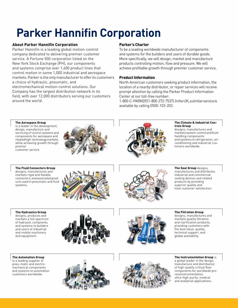
The Aerospace Group is a leader in the development, design, manufacture and servicing of control systems and components for aerospace and related high- technology markets, while achieving growth through premier customer service.
The Fluid Connectors Group designs, manu factures and markets rigid and fl exible connectors, and associated prod-ucts used in pneumatic and fl uid systems.
The Hydraulics Group designs, produces and markets a full spectrum of hydraulic com pnents and systems to builders and users of industrial and mobile machinery and equipment.
The Automation Group is a leading supplier of pneu-matic and electro-mechanical components and systems to automation customers worldwide.
The Climate & Industrial Con-trols Group designs, manufactures and markets system-control and fl uid-handling components and systems to refrigeration, air-conditioning and industrial cus-tomers worldwide.
The Seal Group designs, manufactures and distributes industrial and commercial sealing devices and related products by providing superior quality and total customer satisfaction.
The Filtration Group designs, manufactures and markets quality fi ltration and clarifi cation products, providing customers with the best value, quality, technical support, and global availability.
The Instrumentation Group is a global leader in the design, manufacture and distribution of high-quality critical fl ow components for worldwide pro-cessinstrumentation,ultra-high-purity, medical and analytical applications.
Parker’s CharterTo be a leading worldwide manufacturer of components
and systems for the builders and users of durable goods.
More specifi cally, we will design, market and manufacture
products controlling motion, fl ow and pressure. We will
achieve profi table growth through premier customer service.
Product InformationNorth American customers seeking product infor mation, the
location of a nearby distributor, or repair services will receive
prompt attention by calling the Parker Product Information
Center at our toll-free number:
1-800-C-PARKER (1-800-272-7537). In the UK, a similar service is
available by calling 0500-103-203.
About Parker Hannifi n CorporationParker Hannifi n is a leading global motion-control
company dedicated to delivering premier customer
service. A Fortune 500 corporation listed on the
New York Stock Exchange (PH), our components
and systems comprise over 1,400 product lines that
control motion in some 1,000 industrial and aerospace
markets. Parker is the only manufacturer to offer its customers
a choice of hydraulic, pneumatic, and
electro mechan ical motion-control solutions. Our
Company has the largest distribution network in its
fi eld, with over 12,000 distributors serving our customers
around the world.
Parker Hannifi n Corporation

Wor
ldw
ide
Man
ufac
turi
ng L
ocat
ions
Parker Hannifi n CorporationFiltration Group
Global Headquarters
6035 Parkland BoulevardCleveland, OH 44124-4141T 216 896 3000, F 216 896 4021www.parker.com
North AmericaCompressed Air Treatment
Filtration & Separation/Balston242 Neck Road Haverhill, MA 01835-0723 T 978 858 0505, F 978 858 0625 www.parker.com/balston
Filtration & Separation/Finite
500 Glaspie Street, PO. Box 599 Oxford, MI 48371-5132 T 248 628 6400, F 248 628 1850www.parker.com/fi nitefi lter
Purifi cation, Dehydration and
Filtration Division
4087 Walden Avenue Lancaster, NY 14086 T 716 685 4040, F 716 685 1010 www.airtek.com
Sales Offi ce 5900-B Northwoods Parkway Charlotte, NC 28269 T 704 921 9303, F 704 921 1960 www.domnickhunter.com
Engine Filtration &
Water Purifi cation
Racor 3400 Finch Road, PO Box 3208 Modesto, CA 95353 T 209 521 7860, F 209 529 3278 www.parker.com/racor
Racor 850 North West St., PO Box 6030 Holly Springs, MS 38635 T 662 252 2656, F 662 274 2118 www.parker.com/racor
Racor 302 Parker Drive Beaufort, SC 29906T 843 846 3200, F 843 846 3230 www.parker.com/racor
Racor -- Village Marine Tec. 2000 West 135th StreetGardena, CA 90249T 310 516 9911, F 310 538 3048www.villagemarine.com
Hydraulic Filtration
Hydraulic Filter 16810 Fulton County Road #2 Metamora, OH 43540-9714 T 419 644 4311, F 419 644 6205 www.parker.com/hydraulicfi lter
Process Filtration
Process Advanced Filtration2340 Eastman Avenue Oxnard, CA 93030 T 805 604 3400, F 805 604 3401www.parker.com/processfi ltration
EuropeCompressed Air Treatment
domnick hunter Industrial Dukesway, Team Valley Trading Estate Gateshead,Tyne & Wear England NE11 OPZ T +44 (0) 191 402 9000, F +44 (0) 191 482 6296www.domnickhunter.com
Hiross Zander
Padova Business UnitStrada Zona Industriale 435020 S. Angelo di Piove Padova, ItalyT +39 049 9712 111, F +39 049 9701 911www.dh-hiross.com
Hiross Zander
Essen Business UnitZander Aufbereitungstechnik GmbHIm Teelbruch 118D-45219 Essen, GermanyT +49 2054 9340, F +49 2054 934164www.zander.de
Parker Gas SeparationsOude Kerkstraat 4P O Box 2584870 AG Etten- Leur, NetherlandsT +31 76 508 5300, F +31 76 508 5333
Engine Filtration &
Water Purifi cation
Racor Shaw Cross Business Park Churwell Vale Dewsbury, WF12 7RD England T +44 (0) 1924 487000, F +44 (0) 1924 487038www.parker.com/rfde
Racor Research & DevelopmentParker Hannifi n GmbH & Co KGInselstrasse 3 – 5 70327 Stuttgart GermanyT +49 (0)711 7071 290-0, F +49 (0)711 7071 290 -70 www.parker.com/racor
Hydraulic Filtration
Hydraulic Filter Stieltjesweg 8, 6827 BV P.O. Box 5008 6802 EA Arnhem, Holland T +31 26 3760376, F +31 26 3643620 www.parker.com/eurofi lt
Urjala Operation Salmentie 260 31700 Urjala as Finland T +358 20 753 2500, F +358 20 753 2501 www.parker.com/fi
Condition Monitoring Center Brunel Way Thetford, Norfolk IP 24 1HP England T +44 1842 763299, F +44 1842 756300www.parker.com/cmc
Process Filtration
domnick hunter ProcessDurham Road, Birtley Co. Durham, DH3 2SF England T +44 (0) 191 410 5121, F +44 (0) 191 410 5312 www.domnickhunter.com
Asia Pacifi cAustralia 9 Carrington Road, Castle HillNSW 2154, AustraliaT +61 2 9634 777, F +61 2 9899 6184www.parker.com/australia
China 280 YunQiao Road JinQiao Export Processing Zone Shanghai 101206 China T +86 21 5031 2525, F +86 21 5834 3714 www.parker.com/china
India
Plot EL 26, MIDC, TTC Industrial AreaMahape, Navi Mumbai 400 709 IndiaT +91 22 5613 7081, 82, 83, 84, 85F +91 22 2768 6618 6841www. parker.com/india
Japan 626, Totsuka-cho, Totsuka-kuYokohama-shi, 244-0003 JapanT +81 45 870 1522, F +81 45 864 5305www.parker.com/japan
Korea 1-C Block, Industrial Complex of Jangan,615-1, Geumui-Ri Jangan-Myeon, Hwaseong-City Gyeonggi-Do, KoreaT +82 31 359 0771, F +82 31 359 0770 www.parker.com/korea
Singapore11, Fourth Chin Bee RoadSingapore 619 702T +65 6887 6300, F +65 6261 4929www.parker.com/singapore
Thailand 1023 3rd Floor, TPS Building Pattanakam Road, Suanluang, Bangkok 10250 Thailand T +66 2717 8140, F +66 2717 8148 www.parker.com/thailand
Latin AmericaParker Comercio Ltda.
Filtration Division Estrada Municipal Joel de Paula 900 Eugenio de Melo, Sao Jose dos Campos CEP 12225-390 SP Brazil T +55 12 4009 3500, F +55 12 4009 3529 www.parker.com/br
Pan American Division - Miami 7400 NW 19th Street, Suite AMiami, FL 33128T 305 470 8800 F 305 470 8808www.parker.com/panam
Africa Parker Hannifi n Africa Pty Ltd Parker Place, 10 Berne Avenue, Aeroport Kempton Park, 1620 South Africa T +27 11 9610700, F +27 11 3927213www.parker.com/eu
© 2011 Parker Hannifi n CorporationCatalog 2300-14 USA


