
FREE VIBRATIONS OF A VIERENDEEL GIRDERH
byPatrick Francis Gunniff
Thesis submitted to the Graduate Faculty of the
Virginia Polytechnic Institute
in candidacy for the degree of
MASTER OF SCIENCE
in
STRIJCTURAL ENGINEERING
APPROVED: APPROVED:
ZéßéßiqDirector of Graduate Studies of DepaentT;
of Engineering ä%fessor in Cärge of Thesis
June, 1956
Blacksburg, Virginia

.. 2..II,
TABLE OF CONTENTSQPage Q
I, TITLE PAGE . , . ,,....,.,...,.., , , 1A
II, TABLE OF CONTHVTS,.,,,,.,.,.,,, , , , , 2ListofSymbo1s,,,,,.,,,,,,..,, 3List of Figures...., ,.,.,....., 5
III, INTRODUCTION , ,,,,,...,,.,,.,, , . , 6 ·
IV, THE REVIEW OF LITERATURE ,,.,.,,,..,.,, 7V,”
THE INVFSTIGATION . ,..,.,..,.,., , , , llA, The Principle of Virtual Displacanents, . . ll
B. Method of Dynamic Moment Distribution . , , 30VI, APPLICATION TO A VIERHIDEEL GIRDER.....,, . . LL
VII, DISCUSSION OF RESJLTS. ,,.,,,, , , . , , , , , A6
VIII, ACKNOWLEDGAENTS , , ,..,,.,,.....,,, 1+8
IX. BIHLIOGRAPHY . , , ,,.............., A9X,VITA..,,,,,,,,,,,..,..,..,,,50
XI. APPENDIX .....,.....,.,,.,...., 51

l... 3 -
LIST OF SYMBOLS
A. Symbols Used in Virtual Disglacament Eggations
E Young' s Modulus
Fi Force acting at the bottom of joint i
g Acceleration of grav1ty
Hi Axial force in girder i
hi Lmgth of girder 1hi Conversion factor from I to Ic
Ii Moment of inertia of girder i
Ic Conversion parameter for I and J
Ji Moment of inertia of column 1L Height of all columnsLi Conversion factor from J to IcM Bending moment acting on the girder
Qi Mass concentrated at bottom joint 1J
p Fundamental frequency
R Statical reaction at a support
Ti Axial force in column 1
Ui Static deflection at bottom joint 1
Vi Vertical shear in girder 1
x Variable distance in the horizontal direction
y Variable distance in the vertical direction

11... 4, -
Y1 Horizontal shear in column 1Z Ordinate of the shape function
B2 Säle Used in Mommt Distribution EÄations
wb Conversion factor for length
c Conversion factor for weight
d Conversion factor for moment of inertiah Conversion factor for kt, ,10kl Frequency parameterK Stiffness factor _r Reaction at the far end of a beam due to a unit pulsating momentat the near end•rl Reaction at the near end of a beam due to a unit pulsating momentat the near end•w Uniform weight
Xi True displacement of column 1
¤< Slope at one end of a beem due to a unit pulsating moment at thesame endß Slope at one end of a beam due to unit pulsating moment at the
opposite end of the beam
$0 Tabulated parameter for the non•disp1aced end of a member
yr Tabulated parameter for the displaced end of a mmber
J Oscillating displacement of unity
.. 5 ..
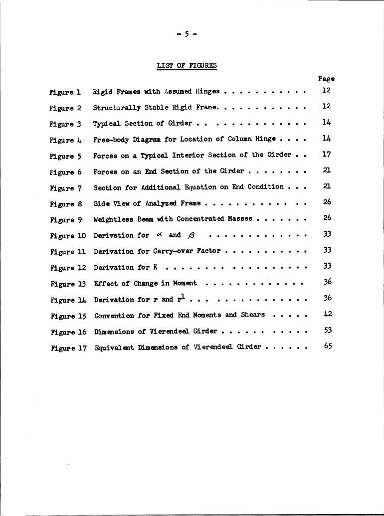
LIST OF FIGURESPage
Figure 1 Bigid Frames with Assumed Hinges . . . . • . . . . . . 12
Figure 2 Structurally Stable Rigid Frame. ........... 12
Figure 3 Typical Section of Girder . . „ . ....... . . . IL
Figure I. Free-body Diagram for Location of Column Hinge . . . . ll;
Figure 5 Forces on a Typical Interior Section of the Girder . • 17
Figure 6 Forces on an End Section of the Girder . . . . . . . . 21
Figure 7 Section for Additional Equation on hd Condition . . • 21
Fl
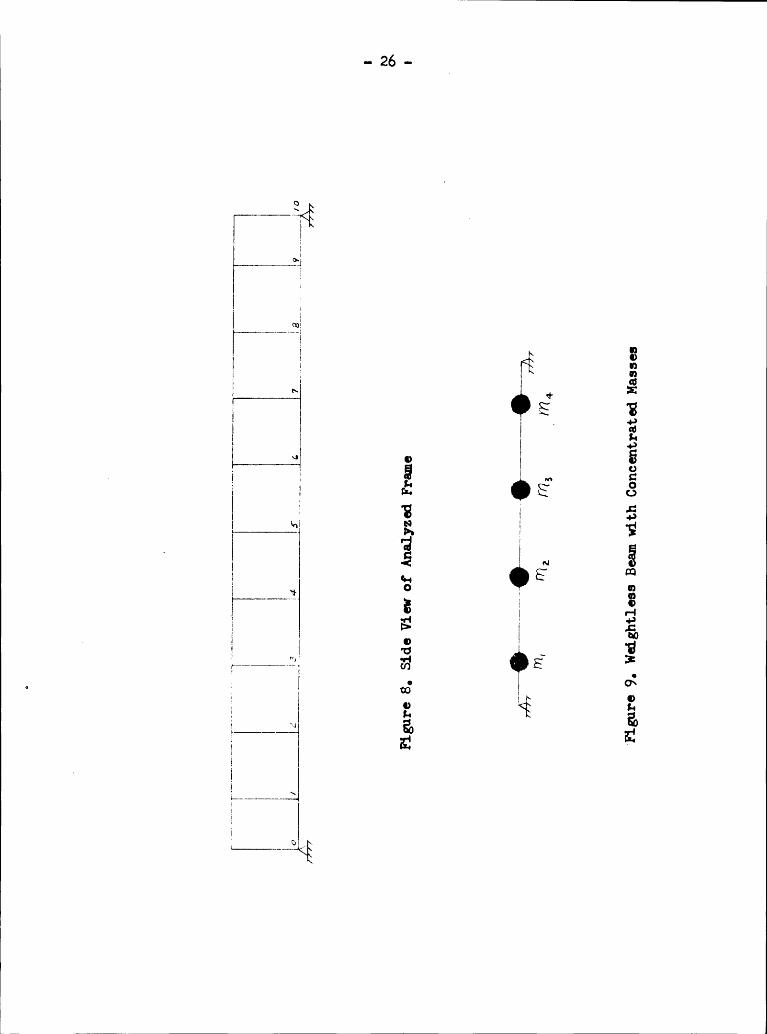
Figure 8 Side View of Analyzed Frame...... . . . . . „ . 26
Figure 9 Wedghtless Beam with Concentrated Kasses . . . . . . . 26
Figure 10 Derivetion for ¤< and ß . . . . . . . ...... 33
Figure 11 Derivation for Carry-over Factor . . . . . „ . . . . . 33
Figure 12 Derivation forK . • . . . . . . .....„„ . • • 33
Figure 13 Effect of Change in Kommt . . ...... ..... 36
Figure1ADerlvationforr‘andrl.•. ............ 36
Figure 15 Convention for Fixed End Moments and Shears . . . . . /+2
Figure 16 Dimensions of Vierendeel Girder . . „ . . . . . . . • 53
5 Figure 17 Equivalmt Dimensions of Vierendeel Girder . . . . . . 66
W—
.. 5 -
III. INTRODUCTION
Vibrations occur in many engineering structures and frequently can
be a controlling factor in the final design for a given structure. The
basis for the design procedure can be the fundamental frequency of
vibration of the structure. The determnation of this value will vary
from probleu to problem and can be a laborious task for certain structures
if one considers all factors entering into the governing differmtial
equation.
The purpose of this thesis is to determine and compare the funda—
mental frequmcy of free vibrations of a parallel chord Vierendeel
, C girder based upon two methods. The first method consists of the
application of equations derived from the principle of virtual dis-
placaaents for the particular rigid frame. The second method is the
application of a numerical method of convergence introduced in a
paper by Raithel (1), which is an adaptation of the Cross method of
staticil. moment distribution.
J

..
7IV.THE REVIEW OFLITERATUREA
statical analysis of Vierendeel type trusses based upen the
principle of virtual work is presented in a paper by Young(2). For
the syrmetrical case, the author writes an equation for the horizontal
displacement of the udpoint of a typical interior column with respect
to the midpoint of the adjoining column in terms of shears and bending
momaxts using virtual work. Assuung this relative displacenent is
zero and using the basic equation of equilibrium at different sections,
he reduces the original equation to the form from which the horizontal
component of axial stress for any chord member may be conveniently cal-
culated. At this point it should be noted that the equilibrium virtual
loading consists of unit loads applied in the opposite horizontal
direction at the midpoints of each column.A
For a parallel chord truss with a constant moment of inertia, the
equation rechnces to the form:
where,
Plbw • the horizontal shear at the center of column bt Hm, - the horizontal shear at the center of column a
L • length of girders
D - depth ef truss
Hu - the total traverse shear in a columnlib - external mment about joint b
Vab • vertical shear in panel ab

3 ...
Thus, an equation for each column can be written and from the resultingsdmultaneous equations, one can determine the horizontal shear in each
web member. „
For the unsymmetrical case, Young writes an equation for the relativehorizontal displacenent between two adjoining columns at thedr joints,
considering the lower portion of the truss only; and an equation for thesame points considering the upper portion of the truss. The two equations
are equated to each other and the resulting equation reduces to the fom
of equation (a) for a parallel chord Vierendeel Truss.
The importance of dynamic loads in structural design is presentedas a general review in a paper by Wilbur and Hansenü). The authors
discuss the causes of dynamic loadings such as, earthquakes, wind, man-
made forces, and shock and blast waves from atomic bombe. An important
fact brought out by the authors is that the designing engztneer should be
discreet in using enpirical formulae pertaining to the dynamic analysisfor a given structure. Thus, the use of static loads as equivalent
dynamic loads for structures whose dynamic response may be condderably
different from the static response can lead to a faulty design.
Many authors have aasumed dynamic response of rigid frames is
equivalmt to the dynamic response of beams of varying cross sections.
A single example of this is the tall frame treated as a cantileverbeam. Glovera) uses this technique in studying the earthquake response
of a tall tower. Due to the translation of the support caused by theearthquake, he adds to the governing differential equation for a beam
with fixed mda an additional term to account for a constant force
ä_

1applied to the support. A particular integral is added to the solution
of the differential equation which represents the general shape of the
static deflection of the beam under the constant loads produced by the
acceleration. The governing differential equation is:
where
K • viscosity constant
A • weight per unit of length of beam
X - acceleration due to a quake
The left side of the equation represents the usual form of a beam in
vibration which considers danping and is equated to the force acting at
the support resulting from the translation of the beam• The solution of” the differential. equation will contain constants of integration which
are determined from the boundary conditions of the besm, and an initial
condition that the beam is undeflected at time equal to zero•
When a structure oscillates in a state of free vibrations, the fact
that no matter how irregular the disturbing forces may be, the structure
seeks to adjust its deflected position to one of the mode shapes of free _
oscillation, is presented in a paper by Goldbergß), By assuming an
initial deflected position of a structure, one can find a new set of
deflection values at each joint by using the slope-deflection formulae•
Thus, the process reduces to a method of successive convergence from
wich a final assumption of deflections correspond reasonably well to

- lO - ;the deflections found by the final analysis using the slope—deflection
formulae. Finally, the energy method, which is based upon the
assumption that when the kinetic energy is zero the potential energy
is a me.ximum,~and vice verse, and that the total energy rmains con-
stant, gves rise to the following equation for free vibrations:
P Cc)where p is the fundamental frequency; g, the acceleration of gravity;
W, the incrennents of weight; and y, the static deflections. It has
been noted that this method is similar in form to the Stodola-•
Vianello method.
A method which utilizes converpng approximations of the funda-N
mental frequency of multi-story buildings has been published by
Raithelu) and an extended explanation and example problm pertaining
to this method has been presented es a thesis by Svd.ft(6). The method
' is an adaptation of the Cross method of static moment distribution, and
is discuesed in detail and applied to an example problem in this thesis.
An unpublishsd method to determine the natural frequency of
lateral vibrations for elastic beams has been suggested by l·Iarcus*
" which utilizes the prineiple of virtual displaceuents. A thesis by ·
Lee(7) has been written using this method for beams of constant and
variable cross·-sections, and the work includes several examples under
various end conditions. A detailed explanation of this method will also
be presented in this paper.
* Dr. Henri Marcus, Consultant, Mechanics Division, Naval Research .Laboratory, Washington, D. C.
4 e - -

.. jl -
V. THE INVESTIGATION
A. The Princigle of Virtual Displacaaents
1. Structural Stability of Riggd Frames
The statical analysis of rigid frames can be performed by the
conventional methods of analysis, such as, moment distributions, slope-
deflection equations, column analog, or the classical methods based
upon the principles of energy. For certain indeterminate problems,
these methods may be laborious and thus, points of inflection are
sometimes assumed at certain positions for a given structure. By
assuming a sufficient number of points of inflection, the problen
can be reduced to a. fom in which the equations of statics are suf-
ficient to determine the shears and moments acting in the structure.
h Now, if one were to assume more points of inflection, or hinges, than
unknowns for a given rigd frame, the stability of the structure would
be questioned. That is, there would be extra equations to be satisfied
for the probleu.
However, for a given rigd frame with more hinges than required to
reduce the problmx from an indeterminate one to a determinate one, the
direction of the loading will be an important factor regarding the
stability cf the structure. More specifically, consider the frame in
Figure l (a). If one were to start at joint A and proceed to B, C, and
D, calculating the shears in the frame at the joints using the equations
of statics, one would find that the extra equation (for this particular
case)ZMD - O, would be automatically satisfied since the loading is

' - 12 -F ‘
P
ß 6 .6 „ PC .
xl
A, 1.1 AD./ ,’
/ ·, 7 , 7 /
<¤> <¤>
Figure 1., Rigid Frames with Assumed Himges
Figure 2. Stmcturally Stable Frame

.. 13 ..
vertical. However, for the frame in Figure l (b), this would not be
the case since the applied load produces a moment equal to PL about
the hinge at D, and therefore, this frame is unstable due to the hori-
zontal loading.
For the rigid frame in Figure 2, where the points of inflection
are located at the middle of each mmber, it can be shown that the
structure is stable for all vertical loads, both symmetrically and
unsymetrically placed. Thus, if one were to proceed from joint to
joint and to cut sections where desired to find the forces acting in
the member, one would find that the shears, axial forces, and bending .
noments at the last joint would be in equilibrium, and thus all4
equations of equilibrium would be satisfied. In conclusion, for the
unsymetrical vertical loading of a frame similar to Figure 2, the
structure is stable.
2. Basic Assumptions
A typical section of the parallel chord, Vierendeel girder to be
analyzed is shown in Figure 3. The following assumptions are made to
reduce the complexity of the problem
a. I-Iinges are placed at the centers of all girders.
b. The vertical shears, V, in the upper and lower glrdersof a given panel are equal in value to each other.
c. The masaes are concentrated at the lower chord joints.
d. When the truss deflects as a unit, the points of in-flection in the columns are aasumed to deflect only ina vertical direction.

- lg -
K5H6 . I}-{b„\1
. V5 Ilg
/)O¤(—_•F——
/70;;P-—
Vab
E 5 g
{ Figure 3, Typical Section of Girder
W
B VI/Z :¤
er , . _ _ I JV, {I
AVi
I II F II·—Figure1+, Free-body Diagram for Location of Column Hinge

- 15 -
If the distances between panel points are equal to h, a natural
conseuence of the first tw assumptions will be a hinge at the middle
of each column. This can be proved by considering a typical free—body
diagram.of an.interior section shown in Figure h. Thus, for the givensection, the following equations of statics will locate the distance
"Y" from the upper chord for the hinge in the column.
Zv=o=aM—F—zMM,== M —.lig
Sum the moments about the lower left hinge.
2(M‘*§)h~+FQ-+4L·~BL=0
5_ A e-
gg-zM;?_Nowtake moments about the hinge in the column considering a
section above the hinge.=0
Mh
Ü:Sincethe distances between joints for a Vierendeel girder are
uually equal, with the exception of the exterior panel, points of
inflection at the middle of each column will be assumed for the general
case.It should be noted that all bending moments are assumed to act in
a elockwise direction about the joint; all vertical shears in the girders
are assumed to act clockwise about the joint; and all horizontal shears
in the columns are assumed to act counterclockwise about the joint.
Wllll____________________.........................................................J

.. lé ..
3. Derivation of "@ations
8,. ypical Interior Joint
Consider the typical interior panel in Figure 5 (a) showing
the real forces acting upon the structure, and the equilibrium virtual
loading shown in Figure 5 (b). Applying the principle of virtual die-
placements for this set of loading, and letting u denote the real
vertical displaeemmt at the lower joint, we have[M _M
J«•‘
L/L I
Aseuming a constant noment of inertia for each member, upon
integration, equation (1) reduces to the following form:
7%.6,.,
Introduce the following relationshipe:
/7'= ls. /7 1’= .1.; 4 „... 611I J
and let

- 17 ~ _
Z T —I 4 ° 4 7*Y; -.„I„____ Y; <__; yi ‘ iV_g_4 4
»«II J 4 VA IÄ A 7’ °
(6)
L ~—~»—L WL -4IV ‘Ln
CX O ii-LI- —_•7
I Y “ I */I 4 VL .- „ + I ‘ /
I(b)
I IH. ;IIQ-— ~' L ,
4./, .7I I I 4* 4, :2 „ Z V g—‘ 7 77 77
I 4 I I ‘7 III, r_
fl FV(c) (.1)Figure 5., Forces on 6 Typical Interior Section of the Girder

N - 18 - ISubstitute the above relationships into equation (2) and the equation I
can now be written as:
E-4-
4
Equation (3) can be reduced in terms of vertical shears in the grders
by considering the sections shown in Figures 5 (c) and (d),
Thus,
Y;L + ab —Z°h .... (C)
V“‘· ° V···¤'·/ét -·--(ar)
Similar eacpressions can be written for the other joints, Since the
hinges are at the center of each girder,
Mm. = (4;]
· Now substitute equations (c) and (e) for V and H into equation (3),
LL =[u,, 6,, [+4., 6,, 1
14,,Userelationships similar to equation (d) to reduce equation (1+) in
terms of the forces at the lower joint,
L.; 6 , fl ., élU,+
uba. h0¢..h;0. __< Ka + /705 bei2 é 2 ,
or j
N CC = -(»€b,.,+/*1/2,,,,+-/‘Z/1„,,)%:·.:— 5/#:6;gg; 4/1,,LÄ, /7...LZ 6 ¢’
Id. _’ éqeééad) i, .. . .. (6*)s
1
- 19
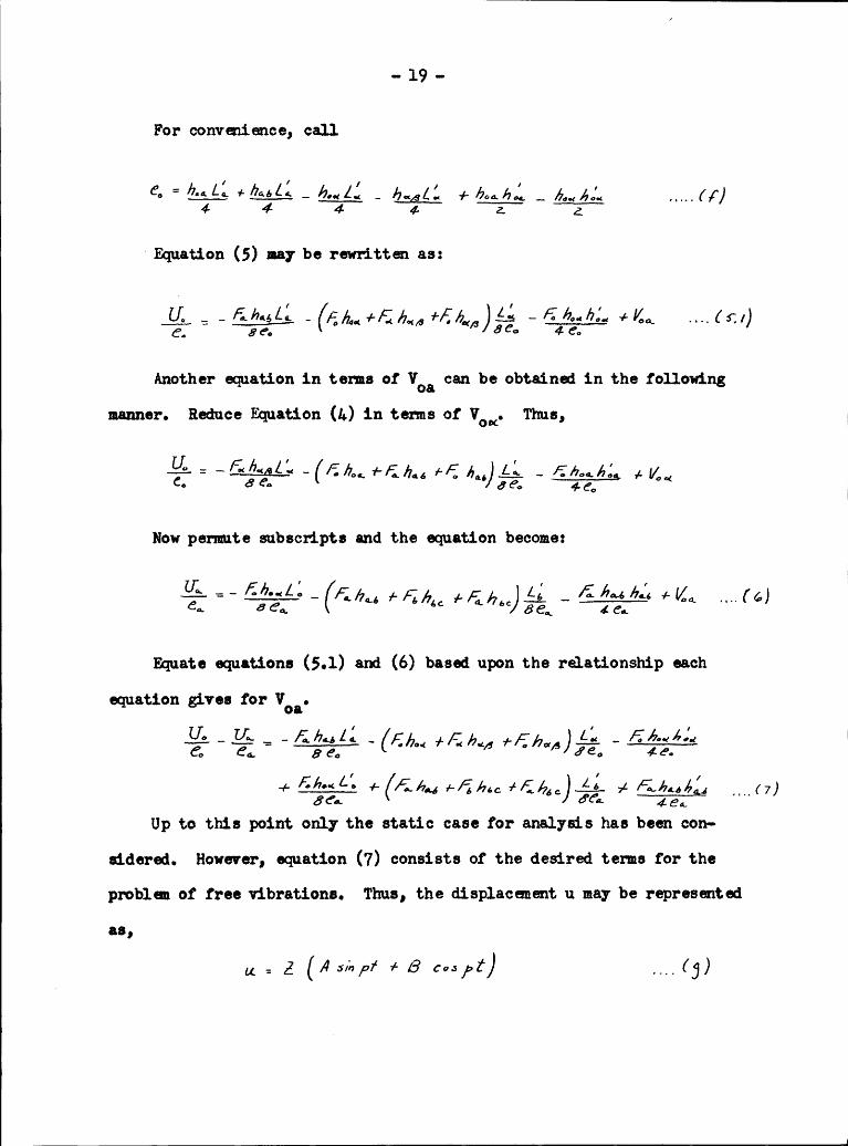
—Forconvenimce, call
@. /7%,1; 1.../.; ,....1/*}4 4 4 4- 2. g
‘ Equation (5) may be rewrittm as:
Z - ügäél (6:/)
Another equation in terms of VM can be obtained in the following
manner. Heduce Equation (1+) in terms of Vox. Thue,
Hg. = Ji/v., 11, - F/7 F F 1' F/7 ’„ca oc f' ¥' (Lag
Now permute subseripts and the equation become:
Ma "’
Equate equations (5.1) and (6) based upon the relationship each
equation gives for Voa....gf...Ij-•*~__-/lb; l;_ F - [.:1../€’A••zA;
>¢ ...,67)Up to this point only the static case for analysis has been con-
sidered. However, equation (7) consists of the desired terms for the
problau of free vibrations. Thus, the displacement u may be represented
as,
1
- 20 - {{
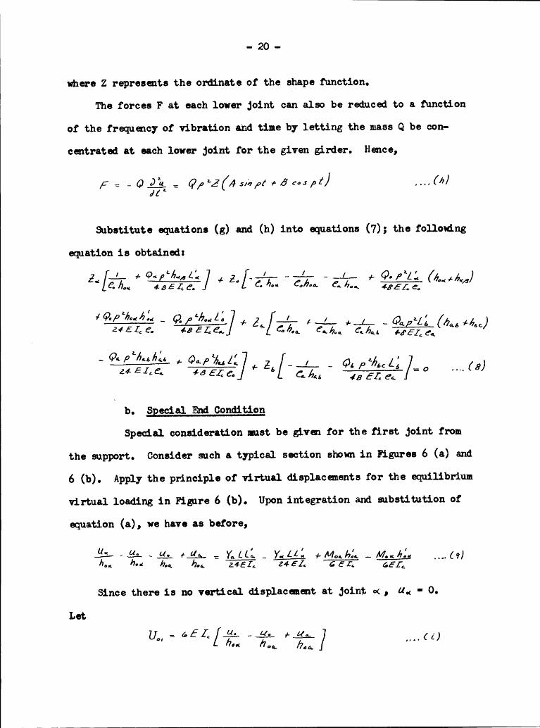
where Z represents the ordinate of the shape function.
The forces F at each lower joint can also be reduced to a function
of the frequency of vibration and time by letting the mass Q be con-·
centrated at each lower joint for the given girder. Hence,
dt ‘
Substitute equations (g) and (h) into equations (7); the following
equation is obtained:
g_‘[;. +G-{*6. LL] _ / Q_/xl; 0Ö /7,., 485£g_ 4- Ö, jh.; Ö,,Ä„„, (_ /,„_ + (é"*é‘/8)
~/Qpzhibfü ._ L I
6064,—
Q<P°"·:/7*: + Gap? Z' '__b.
Special End Condition
Special consideration mst be Qvm for the first joint from
the support. Consider such a typical section shown in Figures 6 (a) and
6 (b). Apply the principle of virtual displacanents for the equilibrium
virtual loading in Figure 6 (b). Upon integration and substitution of
equation (a), we have as before,
-*9:- -9-hm *1.2 246Z. Z4 EZ. "Z?TrT 65,;
Since there is no vertical displacment at joint ¤< , ud • O.
Let
{1{
1
-

I QI
- 2l -‘
II
E 2; 7; 'IL«»- x:- L:M- ’
oc O.LIII . I VI ,R E FI I
(a)
T
-;-I II,. I; Q III; ..I Y III I I „ °‘I EI Ü I
:1 Q .1. °C I IH ¤<Q „, • xy ” Y
I I I ICIl . I \
Ö T ·*· + el: .L
(b) (<=)
Figure 6. Forces on an End Section of the Girder
I
Il "/QQ
I
YÄ 4 M Ü _ _ -——.
II (X O T I
I I I. I I” ‘I¢I
Äh {L Ä- I IIa) ¤·< (b) M1 _ ,
Figure 7, Section for Additional Equation on End Condition I
I I

„ 22 -
Equation (9) is thus written:
ll, = IQLL.1 + M4,4 4; — MN gd _,,_(«s)4 4
From Figure 6 (c), by summing moments about the support, the
following relationship holds:
Y‘ = Vg.; has. ·
_Nowsubstitute equation (3) and expressions similar to equations
(c), (d) and (e) into Equation (10).
- - . - 4.; 1 I4. 6..41CL. — [041 !;)6... +(I/... Lg./2... />.f_4
ZG1'
8 4LI / I I—/- K4.; (—-—Z—-—- +&.£ä·-é; ·- h·=;Ä..·¢.- +4-·;6e¤. -é,,„1Zé,,,4) ____(/4,;)
Let
60/_:
+ ba~· 664
/
4Thus,
LJ;] ' [?:=—/¢E„6..„+€/z..+Fih../äaféa-·‘I./62,/za. +I/,,.. ....(//)ol ¢ cl
To reduce equaticn (ll) into the dynamic form, it will be desirable
te eliminate the vertical girder shear, VO,. . To do this, consider the
IIII
¥ — V I

.. 23 ..
real loading in Figure 7 (a) and a new equilibrclum virtual loading in
Figure 7 (b). Once again apply the principle of virtual dieplacmentm
(1g)hdd hoc! 0
_-° 6**
460 Ä
U--.
Since the mpport has no vertical movaaent C4,.-
O, it followe that
upon integration, equation (12) reduce: to the form:
or
ya Z hui.
,.Heduceequation (13) to the equivalent vertical shear tems for
Y and M. Hence,
IZ A_:
Ke! bag + Vde! hg; bg';
or
Z1)
E Z;"*/7,. (4..+/1,,,)Substitute equatien (lk) into equation (ll).
UM “ IZELLA +/E/7 /'FÜ6/‘—""L;” ’ ——-—-—-——-Ä/7‘:°“(’—’_/I
d OL

2;, - I1
By substituting equations (g) and (h) into equation (15), the 1
desired dynamic form of the equation is obtainad,— +% = [ff-622.,/7.; —@.z,,&,„,,— 6; 2; Ä?8 8··« ¢6.,
er 1_ 1 __ 1 a ' „Z./75;; E+2..[ä—;
+ M1y Thus, for a parallel chord Vierendeel girder of n interior joints,
one can now write n equations based upon the derived expressions of
equations (8) and (16), There will ba however (n + 1) unknowns sincethe frequency term, p2, will be in each equation and since none of the
Z values is zero, the daterminant of the n equations is equated to zero,
It sheuld be mmtioned here that this method is somewhat similar
to the Raleigh method for beams in that this latter method equates the
maximum potential enery to the maximum kinetic mary as determined
from an assumed deflection curve, If the correct deflection curve is
assumed, the exact answer for the fundmental frequency is obtained,
Likewise, in this method, by transposing the static equations to the' dynamic equations in order to find the fundamental frequency, it is
asmmed that an anoloy exists between the static detlections and
dynamic mode shapes,
As praviously mentioned, for a girder of n interior joints, there
will be n equations, However, the number of equations may be reduced
by one-half for a symetrieal bridge, which is frequmtly the case,

- 25 - ]
since Z1 - Znpl, Z2 -Zn_2, etc. The resulting roots for p2 found by
solving the determinant will give the first, third, fifth, etc. modefrequencies. However, should Z1 -
—Znpl, Z2 - -
Z¤_2, etc. be
assuned, the resulting roots for p2 will be the even mode frequencies.
L. Special Consideration for the Eggation of an Interior Joint(
Figure 8 shows the number of panels for the Virndeel girder tobe analyzed in this paper. It has been found from experience, that
for this particular problem which has an odd number of interior panel
points, a special equation for joint four should be derived. The
typical sections and virtual loading as shown in Figure (5) will be
the same for this joint, and the following relationships between thesubscripts will be
°<:‘·?
0:4-Equations(5.1) can be written for the particular subscripts.
(F +FA +FA ll FJ4From
symetry,
V46‘ F ° Vo';
·‘ V~= "V“ ’ ij;Sbstituting this expression for VL5 into equation (L), we have,
¢ ¢
··26Q'
Q QQ Q
Q6 ä
‘ Q,Q 2 Y» ' Q:
} -•-v
Q Qä
Q „ §WW
¢•-• ~
Q6 Q
‘ä
0Q
•"*
6E =
Q._._ "
°
ä Q E
Q”·= 6

.. 27 - |
This expression reduces to the following dynamic form:
cThe
reason for deriving this special equation lies in the fact that
e5 equals zero for the symmetrical girder that was analyzed. As a re-
sult, only the ZA and Z5 terms ranained in the equation for joint four,
which would not give a solution to the determinant for the fundamental
frequmcy.
6 5, ggations for the Special Case
For the special case where the momaxt of inertia of all columns, J,
is equal; the momsxt of inertia of all girders, I, is equal; and the
distance between all joints, h, is equal, the general equations can be
reduced in size coneiderably. Since the value of all e's will be zero
for the general expression of an interior joint as represmted by
equation (8), multiply all terms by eo and then let eg • 0. Note that
nothing has been said about ea, The resulting equation will be:
(P 4;EL b 2¢
E12Equation(m) could have been derived directly from equation (5)
since Voa in this latter equation would drop out due to the bracketed
term being zero in value.
For the special md condition, multiply each term of equation (16)
by ecl where,6,, =
LL,4

X X
X·- 28 — I
XHence, equation (16) reduces to: X
.7./-:1. —— ...L2..... @#*4,6. +Q,g‘66i/ [J. §6g’·/[Z, -
6. Additional Approximation of the h_LationsIn the example pmblm for which the derived equations were applied,
the first four frequency modes were obtained. It was decided to neglect
the shear termVw}
in equation (5) for the general interior point, and
te neglect the shearing tem V0,. in equation (10.1). Then, use the
resulting equations for the problan and compare the final answers ofthe fundamental frequaxcies.
Thus, equation (5) is now written:
..I
—- 4 ädéeig
Transpose into the dynamic case and equation (o) reduces to the fermzZ_I/ + CP. @6.. 42/ of - J. 42/3242 6,,,, 744,,, Q
Zi+Z«/vi:
*Forthe end condition, neglect the shear term VM in equation (10.1).
Thus,
Ü.,In
the dynamic form, equation (p) becomes:
a4
__" [A. ’“ ‘*——...·i6 °

- 29 ..l 7. Review ofProcedureForconvenience, the following steps list the procedure to be
followed using the principle of virtual displacements.
. a. Determine the concentrated masses at each lower joint.
b. Calculate hl for each grder and L1 for each column.
c. Celculate s for each joint.
d. Apply the equations derived from the principle ofvirtual displacments.
e. From the equations obtained in step (d), set up thedeterminant ard equate it to zero.
f. Solve the determinant for p2.
.. BO ..
B. Method of Qygamic Moment Distribution
1. Introduction
The basic principle that underlies Raithel‘s method is concerned wdth
the resisting forces that are set up at each joint while a rigid frame is
in vibration. As a preliminary procedure of explanation, consider the
wedghtless beam with masses concentrated at various points, as shown in
Figure 9 (a). If I1 is displaced a unit amount in the vertical direction
while all other masses are held in place, (this will be defined as an
absolute displacenent), and then released, a state of free vibration will
eurist in the system. The forces that act at ml are the inertia force of
the mass itself and the shear, or resisting force, at this point, which
is dependmt upon the movement of all the masses and the absolute dis-
placaaent of nl.If mz is absolutely displaced by a unit mount and released in free
vibration, a new shear value will be set up at ml which will be a function
of the movement of all the masses ard the absolute displacement of mz.
Likwise, by perfoming the same operation for m3 and mh, additional
resisting forces will be set up at ml. Naturally, similar resisting
forces will be set up at the other three masses.
For the actual case of the beam vibrating in its fundamental mode,
by using the Principle of Superposition, an equation offorces at each
mass can be written which equates the inertia force of the mass to the
resisting shear due to each absolute displaceuent multiplied by the true
displacement of each mass. Using the summation convention:
NN
„ ,, 31 ,, ;
Ö = $;,·Xj x.'=/,z,3,____xy_j = /,L, 3, xy
where Fi represents the inertia force of each mass; S13 is the ehear at
1 due to a unit displacauent of mass 3; and XJ is the true displacement
of mass 3•
2• Application to a Rigd Frame
From the preceding discussion of the principle underlying Raithel°s
method, if the beam is replaced by a Vierendeel girder, the concentrated
masses are replaced by columns, and an interesting problem ensues• It
will be recognized that as each column is now absolutely displaced a
unit amount and then released, dynamic fixed md momente and shears
are set up at the respective girder ends, and in turn, are constantly
distributing thaaeelves throughout the vibrating frame. In turn, there
are dynamic 3o1nt rotations due to this distribution of moments and
shears. Also, since the shape of each member is changing with time, a
non-—uniform distribution of inertia force will endet for each member,
which in turn will affect the end shears of each mmber. These special
effects which arise for an oecillating rigd frame vdll be discussed in
detail when the fixed md mommt and shear expressions are derived.
First, however, the dynamic carry·over factor and stiffness factor will
be considered.

.. 32 -
3. Solutions of the Governing ggation
For the dynamic case, the governing differential equation for
lateral free vibrations of a been of uniform weight w, is
E I J4 _ _u5 J: _Tft j 3% 0 '''· (ä)
Solve the differential equation by the method of variables
separable, letting X be the shape function and T be the time function.
The solution for X is
X: A SM IZ4. 4- B cosléqc 4- Cslgl/1..
.. < 0)where 0* t ät? tät ä? H 60
The constants of integration will be determined for the given
beundary conditions. Thus, for a simply supported besm with a pulsating
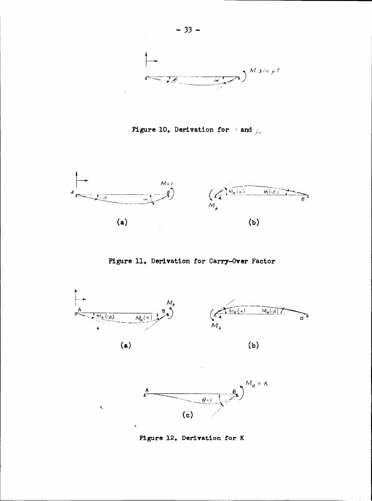
moment(M sin pt) applied at the end of the besm as shown in Figure 10,
theend conditions are:
X(0) :0 ><(L) :0 x"(o) : 0 ;(”(L) : E/MIZ
Having solved for the eonstants of integration, the solution reduees
to the form:
X Z M/aLI
IZ _ _Z 7
- 33 ..
IW 5 /»->‘'””Y—wÄ<?,Ü7^)
Figure 10, Derivation for I·¢ and /3
}—r Mu /'/_______/·R * ‘*—j\.I·_______3_______,-„-\;„‘
A4e A
(a) _ (b)
Figure ll, Derivation for Carry-Over Factor
&’MG____________ll_3__ {/VSi/W5(¤)
(b)
ME = K^—<:————{—~ D\\(
c)Figure12, Derivation for K

I
- 3;, ..
The slopes at the end of the beam are designated <>< and ß .
By taking the first derivative of equation (19); we obtain:
6,/5[ ZF .. ,. (ze)
wb r .. I _
- -V- Z? (sued sj;6
AZ)Luégrg·:zki
The values of lk and gß for various values of kl are tabulated in
Table l• .
For future reference, let <>< be defined as the slope at one end of
the been due to a unit pulsating moment applied at that end, and ß be
defined as the slope at one end of the beam due to a unit pulsating
moment at the opposite end.
lt. Gag!-Over and Stiffness Factor(
For the dynamic case, the carry-over factor for a beam, whose ends
are designated as A and B respectively, is defined es the ratio of the
moment at A to the moment at B due to a unit pulsating moment at B,
while end A is held fixed. For the beam shown in Figure ll (a), it is
observed that for a unit pulsating moment applied at B, a slope of
( -/3 ) is developed at A. To nullify this slope in order to satisfy
the definition of dynamic carry-over, a moment HA must be applied at
end A as shown in Figure ll (b). Now sum the two slopes at md A.
M, :0
- 35 -
Thus, the carry—over factor due to a unit pulsating moment at one
end is defined by equation (22).
The dynamic stiffness for the same beam is defined as the pulsating
moment required at end B to turn end B through a unit angle, keeping end
A fixed. Referring to Figures 12 (a), (b) and (c), in order to satisfythe definition for stiffness, the moment HA must be applied at end A to
keep it as a fixed end after the pulsating moment MB has been applied at
end B. The resulting slope at end B can therefore be written as:
67
=/Fromthe definition of carry-over factor:
M~ ’ M6 .6,„4
: [ - L Ü-Z.__ L’ WS (°‘ß—-e) · Mß(a‘<.;é~—)
MB K = -.··<..-... _____ (Z3)4 ‘ -/5 "
5• Fixed End Moments and ShearsT‘he fixed end mommts and shears are found from equation (19). How-
ever, before proceeding to derive these expressions, due consideration
must be given to the end shears which are affected by the unequal
distribution of inertia force from the girder as the frame vibrates•
Consider Figure 13 (a) which shows the forces acting on the girder and
joints as one end is fixed and the other end displaced an amount 6 •

- 36 -“
D/rccf/00 0% /V76/’/00 1Hp <1/60 i ee
;„i$77€f1F de/;’ /:.7//5/T/ld F0r-r3\.\_ _/'rzgrf/0 7-0r:c*· 76 70/2(a)
f// ij/760/· d/1670 lr/CrfiaForccj*5/Vcor .1uE 70 Chrzngc /0 ^//ICIHCÜ7
6 (b)
Figure 13, Effect of Change in Moment
^"‘/ /v/=/A 6 Ä) (6 A 6 L
1/2’ /7 1
(a) (b)
M6
(¤)Figure 11,. Derivation for r and rl

.. 37 ...
In the actual case, since the joints are allowed to rotate, the fixed endmoments in the girder are distributed throughout the frame as the column
(translates„ Thus, a change in the end moment of the girder will produce
Fan unequal distribution of the inertia forces which depend upon the massof the column. Figure 13 (b) shows the change in moment acting at B
after joint B rotates, and also shows the resulting shears•For the Vierendeel girder, both ends of a girder can have a change
in moment which will effect the distribution of the inertia forces•Figures 11+ (a) and (b) show simply supported beams acted upon by unitmoments at any time; Let rl be the reaction at the end where the
momaxt is applied, and r be the reaction at the opposite support•Figure 11+ (c) shows the applied change in moments at supports A and B asHA and HB respectively• Thus, the reection at A and B are:
Fö»=Re= M„(«·c) + M6 (Ä') (3)
The third derivative of equation (19) is:
· ;=[x"’= -· (Ü
The values of the reactions r and rl in Figure 11, (a) will thereforebe:
6=zx"’(¤) -; /z. = — M an

- 38..where
1- 4 ( 6 ,...6...M;" 7 5,;, kl
AL + co/A ll}
The values of Z/’$— and ß- for various values of kl are tabulated_ in Table 2.
The values for the fixed end moments and shears will now be computed
for a fixed — fixed beam due to a translation of one end by an amount 5 .
The boundary conditions are:
x(¤)=¤ ,666):5 x'(¤)=·-o x'/L/=¤
Upon evaluation of the constants of integration in equation (c),
the solution for the shape function is:
)( : J [(6*1},,éL +5,AA AL)(.vQ• A4. - 5/;}/7 Aa)Z[/ — Ca:4 ÄL casél)
4-(gagéé —¢‘o.sb él)(C¢Jk’!‘ ‘ MS/1 ,••··(/7)
The fixed end moments and shears are determined by taking the second
and third derivatives of equation (h) and multiplying by EI in each case.
By letting Ä • l, the resulting equations are:
M I _ I I I (46)‘(6M46 -coséFW; eubf P
Q, ,,,1,,,,; Q . (,éL)"( :1;, AL 6/CAAL//Z (1
V;cosél cesbét)
EfL’ ”wéere Q : /AL)3(»AAL/2
(/— Cwél CoJÄ kl]
.... (30)

— 39 -
Values for 94 , wr Q4 and az; are tabulated in Table 3
for various values of kl.
6. Conversion Factors for Physical Progerties
For a rigid frme which is composed of meabers with various sizes
and weights, it is convenient to select the mommt of inertia, length
and weight of a member which is most predominant throughout the structure.
These values, however, need not correspond to the same member. Designate
the above selected values as I°, Lo and wg. The corresponding values of
the rauaining members will be some percentage of the reference values.
Thus, by letting the subscript i refer to any other member, the following
relationships are established:
LL.— I .c. ’ !" = “·‘ = ¢‘ rw
From equations (b),
Z6. " Efj
Therefore, a ki Li term with reference to k° Lo will be:
,6,;, = 6, /. ég éßle
"·.Let
6.1. dg 6.;)

1
- ggg..7.
Review of Procedure
The procedure to be followed using Raithel's method is outlined as
follows:
a. Assume a value of kOL°.b. Calculate the carry·-over and stiffness factors for the
members with reference to the tabulated values of ßand gk .
c. Calculate the fixed and moments and shears and also ther and rl values.
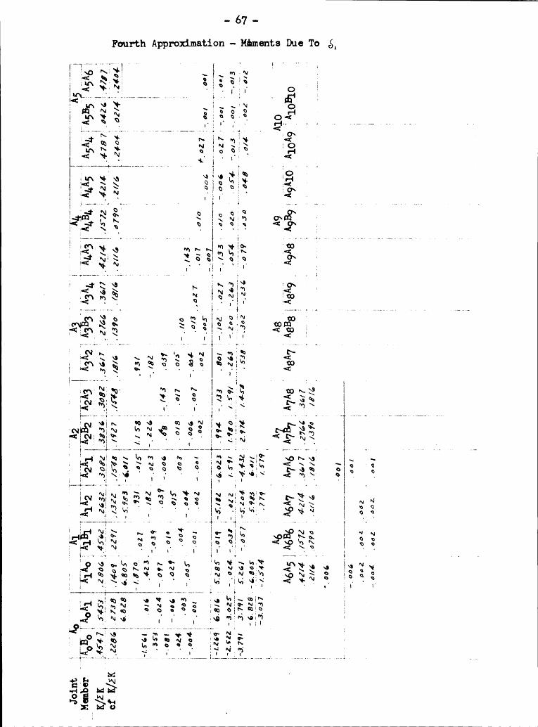
d. Determine the change in moment at each joint by mommtdistribution for each column that is translated anammmt 5 = 1.
e. Determine the final shears at each joint.
f. write an equation of forces at each joint equating theinertia force of the column to the corresponding resistingforces at the joint.
g. From the equations of step (f), a deteminant of high orderis obtained. Solve the determinant using the Crout method*by substituting into (k°L°)l*, the assumed value of k0L° instep (a).
h. Assume a new value of ROLO and repeat the above procedure.i. Plot the value cf the determinant as ordinate and (koLo)l’
as the abscissa. Where the curve crosses the abscissa isthe answer of k°Lo for the problem.
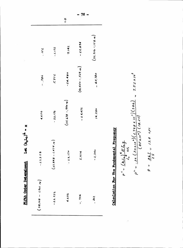
J. Now solve for the fundamental frequency using the equation:
4p‘= (/..1,) EZ.;L} w;
*P. D. Crout, A Short Method for Evaluatigg Deteminants and SolviggSystans of Linear gations with Real or Complex Coefficients, AmericanInstitute of Electrical Hxgineers, published 19l.1.

.. gl ..
Some of the preceding steps in the above outline should be explained
in detail. However, it is advisable at this time to consider the follow-
ing notation for fixed end shears and moments. Figure 15 shows an
arbitrary grder translated. The letter L refers to the end of the
girder being displaced while the end that remains fixed is designated as
the 0 end. The following convention will be used; fl! (L) or f S (L)
will refer to the fixed end moment or shear at the end of the girder
displaced, while fil (o) and fS (o) will refer to the end held fixed.
The final shear computation in step (e) is found at a joint by
adding to the fixed end shear the product of the r and rl values and
their corresponding change in moment, as expressed by equations (f) and
(g). The direction of shears is best determined by drawing a free body
diagram of the momaxts and resulting shears for a particular member.
Generally speaking, the shear resulting from a change in moment is sub-
tracted from the fixed end shear.
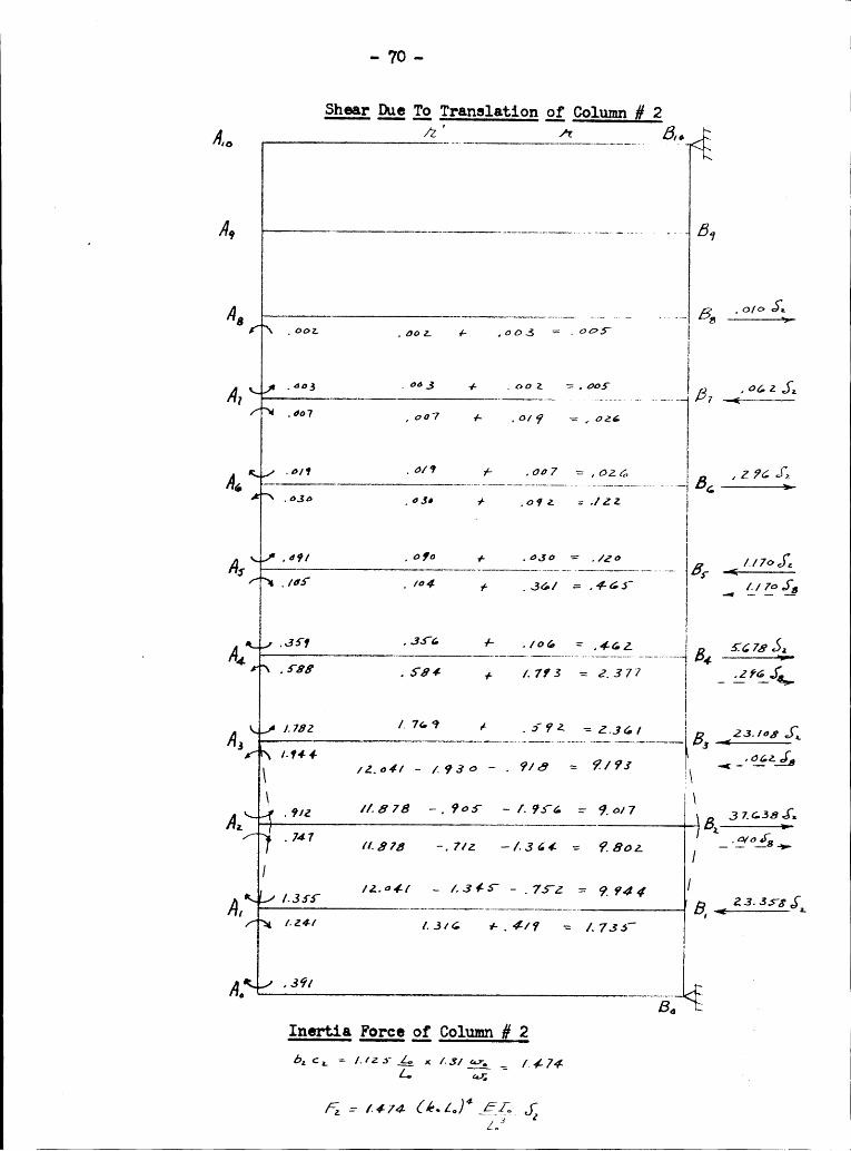
The inertia force cn the column, mentioned in step (f), is equal to
the product of its mass and acceleration as it translates. Thus, for any
translating column iz
5 4.4 wa. $3
These forces are equated to the resisting forces at the corresponding
joint as discussed in the introduction of this Section B. Thus:
(l”«·4·)46.·¢«‘_¢‘—ä__{i_—«;_ X, = 5.;} X; ,„_(s6‘)
‘ K

..]+2..
I5’ 2825
'U1° ° 51 B‘ 51 * ä
.11-*.1—’
{51 1 g
1 1 QIG ¤ E;.
5•r-I5ä8bl0$4ä12
1

- 4,3 ..
Now consider in further detail steps (g), (h) and (i). SinceRaithel's method is one of convergence, one can assume a value of k°L°and then solve the resulting determinant for the lowest root of (k°L°)l*;
substitute this nur value into the procedure and, in turn, find anothertem of k°L°. However, it has been found through experience that thisconvergence is rather slow and the solution for the smallest root of(k„L°)" is a rather tedious operation. Thus, according to step (g)it has bem suggested that the resulting deteminant be solved by theCreut method, which is a continuous operation on a computing machine, bysubstituting the assumed value of k°L¤ into (k°L°)(•·. The graph that isplotted according to step (i) will give the value of k°L° which, ifassumed and in turn substituted into the resulting determinant, will be
. the convergent value seught•
4

.. M, -
VI. APPLICATION TO A VIERENDEEL GIRDEA, Method Based on the Principle of Virtual Displacenents
The symetrical Vierendeel girder for which the natural frequancies
are calculated is shown in Figure 16. The analysis consists of twoparts; one which is based on the derived equations considering thevertical. shearing terms of the glrders and a second which neglects
the shearing tems.
It should be noted that only equations for joints one, two, three,four, and five were written due to the syumetry of the girder.
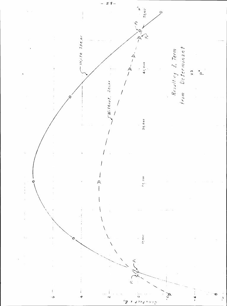
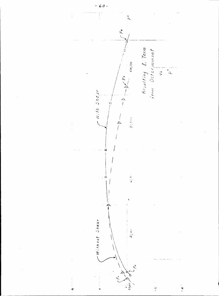
The first four natural frequencies were found in each case.Curves are shown in the appendix with the calculation data which re-
present the resulting terns of the deteminant for various assumptionsof p2. Where the curve crosses the axis, the corresponding value of the
abscissa is the value of p2 which satisfies the determinant.The follovdng results were obtained for the frequencies in cycles
per second.l
Büth V Without V_ P1 10.3 9.3P3 _ 3l•.l+ 33.9Ph 52.6 hß.8

— ns·B.
Raithelks Method
Figure 17 shows the prder with the equivalent I, w, and L for each
manber. The moment of inertia, weight per unit length, and length of
manber AlA2 was chosen as the equivalent I°, wc and Lo.The calculations were reduced considerably due to the symmetry of
the girder. This was particularly noted for the moment distribution
computations.
The values of l;°L° which were assumed are: zero, 0.50, 0.75 and
0.90. The curve of the resulting determinant is shown in the computation
data. The absciesa is crossed by the curve at 0.36. The resulting value
of the first fundamental frequency is 13.8 cycles per second.

·- A6 - II
VII. DISCUSSION OF RESULTS
The results obtained for the Vierendeel girder based on the equations
derived by the Principle of Virtual Displacenents are listed once again.
With V Without V(cpß) (eps)pl 10.3 9.3p2 27.6 2A.OIP3pk
52.6 A8.8
For the first fundamental frequency, a difference in value of about
10% exists between that found vdth V and without V. For the higher mode
frequencies, one would expect this difference to increase, but the results
do not indicate such a trend. There is no apparent season for this
'discrepency.
The value for the fundamental frequency calculated by Raithel's method
was found to be 13.8 cycles per second. A difference of about 28% lies I
between this value and that found by the equations of virtual displacaaents
considering the vertical shear V.
It should be noted that although Raithel's method is the more exact
method of the two used in the preceding example, a considerable difference
in time for calculating the fundamental frequency exists between the two
methods. The time required to determine the first fundamental frequency
based on the equations of virtual displacanents for this particular

1 ·- !+7 -problan required approximately eight hours. To find this same valueusing Raithel's method, required approximately 32 hours.
It has not beax shown by Raithel's method how the higher mode
frequencies can be found. However, such frequencies are a direct result
from the equations based on virtual displacmxents.
As a suggestion for further work in deriving the equations by thePrinciple of Virtual Displacanaxts, it might be advisable to write the
equations based on the vertical displacements of the points of inflectionof each column. The concmtrated mass of each panel would be located at
the center ef the respective columns. This appears to be a betterapproximation than concaxtrating each mass at the lower joint.

·· L8 ·- IVIII. ACKNO’v¤‘LEDGME¤ TS I
The author wishes to extend his sincere gratitude to Professor
Grover L. Rogers who, as thesis advisor, gave generously his aid and
advice to the author in order to overcome the obstacles and problems
that were met while writing this thesis.
He also takes this opportunity to thank all of the pnofessors at
Virginia Polytechnic Institute who, through their class lectures, gave
him the necessary background to write this thesis.
I

- l+9 - {A
IX. BIBLIOGRAPHY
1. A. Raithel, “La Dinamica Dei Sisteai Solidali, Nota II Giornale DelGenie Civile, V. 90, 1953, p. 716.
2. Dana Young, Analysis of Vierendeel Trusses, A. S. C. E. Transactions,
3. J. Wilbur and R.'Hanscn, The Imgrtance of Qgamic Leads in StructuralDesign, A• S. C. E. Transactions, Vol. CT, 1953, p. 753.
L,. R. Glover, Earthgake Stresses in Framed Structures, Proceedings ofthe American Concrete Institute, Vol. 38, 191,2, p. L53.
5. J. Goldberg, Natural Period of Vibration of Buildi Frames, Proceedingsof the American Concrete Institute, Vol. 36, 19l.O, p. 81.
6. G. W. Swift, Free Vibrations of Multi-Steg; Building Frames, Master~ of Science Thesis in Civil Engineering, 195l+.
7. F. Lee, On the Frggency Analysis of Beams with NonellniformCross Sections, Master of Science Thesis in StructuralEngineering, 1955.
C. R. Freberg and E. N. Kmler, Beamte of Mechanical Vibration, SecondEdition, John Wiley and Sons, Inc.


-· 51 - 7
H. APPFZNDIX
A. Calculation of Fundamental Frgmciss UaiggPrinciga ot Virtual Digglacmmts
1. Comggtation Data ·- 161th Shaar Terms
Joint weight1
Mass J L1 o(1n*) (Lxwq) {L)
O ··· ··- 2798 .03861 6730 W 17.1+1+ 51+51+ .0198 .6532 6083 15.76 3912 .0276 1.2393 5237 13. 57 21+02 .01+50 3.1201+ 1+1+27 11.1+7 1166 .0926 15.7155 3770 _ 9.77 290 .03721+ 0
Member I hl( 1%*1*) (L
xO12796 .032212 2798 .031+323 2798 .031+331+ 2798 .031+31+5 2798 .031+3
Joint 1— —-···'° ~ ··—"L"'“' “' Z' za v l饷 /I/LZ'1 alb., ¢’, b·z 6.*211*11,) + 466-/Za—
....4... O; 0%. LÄ _b,.
:0/0 ‘

... 52
..Joint2 I IZfzl/2; 4-*3/ ii
J 3 *4 J 3 3Z 3* *3/“”"” ·‘ EJ GJoint Q
EZÖAVA41]..Z4E1; 64 4/*41 42EL 64gz[333·7 +4%%-] +.43,; 7340 0663 6
Joint Q ·‘ *3/ 3·‘ J=30
Joint QZ4[.é- 4 -.4-. 4 $:222 (6,,+h;)/*4 1 Z4E.L 64 ,4 61*6 48 E1;
4 O4 4 44 8 fjz 64.5 L A16
0

1 · S- 3 —
,3 CQrv;Ä"
I1 1*E ** '( 111
L ;___v_V____ ___ _ _____________________________________ ___ ____;__ _ 1
1 1 * 1° 1 11 Ä Ä1 V7"' ._Q :‘* r ÄÄÜ1 Ä g~ ‘* ;;M
Q, 11 \1 1‘—J ‘,‘
._ J \ 1 QLQ J,)
11 11 11 H 111 •1 11: _ Q ·1 .Ä1 1;* 2 ., 2 E H Q
ÄN 1
11 11 11 1
~ < #1,1,_..........—„...-.—-—--1-1---— 1-~~~ 1~·-—---· ·—·----1 *·*·* Q ’ “1 Q
1 1111, 1 .„ ‘1 ~‘ — 1
·1~ JA ,1 ,1 ‘ x— V‘ Q ; y‘ °+ J {1 { L GM V ,1 1 1 1 111 EQ (Q1 11.
1 1 1-, *1 11 11 J Q · Q1 ~‘1 •» . 1‘ ß__11 •' In ’Q Ä‘* Q ;‘
|| 11 U Ü· 1
1—• <( eq ‘~•. Ä1————-———-———-~—~-—-—~---·——1··—-——·-— -—·· — ———————}-—¤J
1 .1 .‘*· ;;1 Q 1M1rp
ÄÄ”1 Ü 'v~ 1~„ _ T11 Ü,. Q 1.,11—-„ 1 I 111 ng 0 J ’ ·1¤1 ,1 311 1, 1 —' ¤Ä 1 » —1 -5 1 ·' 11 1 Q113I111 111 ~„1 GQ .1,. ¢ E 1..1 4g H <r1 N Ö1 *‘Q 1 1_§Ä
txrw!1 E 11 < ·1 1 ;td
Q ~ s
1 1Q11—1¤~
1: **1 I Ä\— x + {I) 1 1\‘ G] Q! ÜN 1-1 Z 1 "1 · Q 1 II 1l1U
1l nÄ *2
LI) 2 1,1 <( Q.2 *1 < ? 1*7 111 E 2 _ Q- N I1 N 1 1 +
1 2 H <=: M 1 1_1 ”m”/”wÄÄÄ—w*Ä”ÄwÄ —” Ä-
1"‘
1 L1‘1 Q
1 - Ä 1 ‘“z ¤¤ 11 ' 1 Ä1 1 ·__ <>~ Y1 P 1 5
{\, _ — Ü\ "+ \D 1 1L„¤— G, 17 z 1 vu 1*11
~~• ,1 _‘Q]“ V (fx Äa Ä 1 11 5 11} ,__ Ä
r\|‘\
1 1 11 -AÄJ J Ä} AQ &11 11 11 - 1~ ~• 1 E *1 1 1<
I‘\] "~l \) 1 1 U H glI1 11 11 Ä11 ‘ 3 1—1
1 11 11•1·^·····—· 0 —/ Q1 -·——*-Q **-1

• 51, -
Q
ßde pr
1
OI1
^'‘ T
°MQ1,,*M, M
I‘
Sßu
*•
NQ Q; Q $,2
1 "\ "*
‘
'3S *ß I*
S S 3
•1~
°_ wQ,Q‘
{ä*,7*
ln¤‘"~;sgg
‘i° %~
S·~1~ ,3 3: «»
I+I M
N Q
+
Q2 3Z2 .Q
Qz S ° *
~1~
.,,5 M!
l
\./ Q)7Q,
"¢-\
gsJ
/"'\
•„,L
Ill
bi 9mx!
eq
<\,‘ß
aa
N1 ~1-S
¤ O+
*I-1~.
°9 I! Q
—1~*“ Q', °.C,
7*1* "-\
‘ ·
°~H:3
.¤ *N s ‘~ °*\Q
Q·\
‘I* ‘I- +¤;
I; 0*
9 + ws
QL*/ Q'? I2Q)
6* 1]*1.,,, M2 3,*
~
_&
mr +“'
N +SQ EJ
Q.M4

I
I
r Even Mod8QFr Gncies
Qn
•l‘ e-g^I°\
Ä°°q_ N
Ini"
NICQ $1~I
p +
v~~s:2
S S 3V
W•\I
\} Q
I
°‘ AIÄ /'\Q 6‘ *2
Ä. In .° w
n*\+
.Q o63
$ t~
Ib rr;} ;
Q, „· ¤
·I~
T
=?;"L °§~· ft,~‘ 68 th ~
AIN +_,_
¢~ °
I
S Q ¤~3 v Z2
L4TI V3
*Ä}1*
L T§~• *-
vgl Q4NI ~
QS
*+
'S<¤ T'° S·S ¤_
LL} CJ
II
.. 55 - '
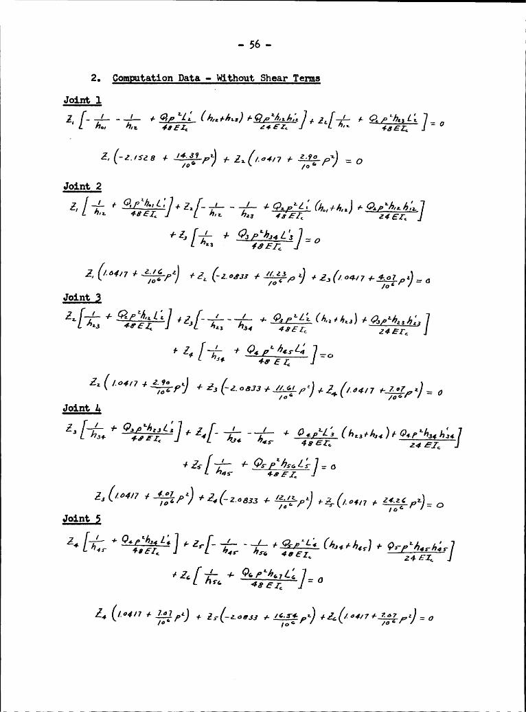
20 Comgtation Data -· Without Shaar TomsJoint 1Z,ho:
hn. {851; Z¢ E-Ze ’°‘{JZ,
0
Joint 2+@
lb"-bl,I hn.==
· {651;
Z, 1- 1- GJoint Q
Z3)+Z
[-4- + OEL ”°
Z= (/.64/7 1;;;,,-): 0Joint gt
l / L I L ¢h{Z3++655 ‘ bg; /1.,,,-
Q-vßzäselg/: 6/,45* 4-651;
Z3 +3 62,, {_ /z,1z 1 ( ZGZG ,_/3; 4 -83.3 Typ +23. /.¤{17 1- OJoint Q
/ 1 ’Z0Z*
45* 5'6 456Z*¢ Z4-
0"‘· 4651;
1- 0

@at.ions for Odd Moda Frggencias
O ·
QJ1 '?‘·~~! 231: Q $¢„ru 1 Z EF Y0_ N
C., W'Jn ‘ NQ Q
3* Q0 I4e ~ 0 ° 0Qx Y N.
* +Q, ‘L
N „ '·2’ *+J Q *3•
~.
0*, xD QL
1~"',§ ‘
~\ ";\
°~Sw ¢"° *;*2JY YJ ¤¢‘„ + I, *N N pv} NF E J§ Ni Q
Y üN, ' \.uJ TQ
1}°~0;* $0ÜY + J1
^' J —L"~* T2E 2 Z1 ~¤ ‘=?
+75 ';\“~ NM°
”32 22NJ * *J ·:Q ~•-
- ¢

n
Eouation
Qgn
Nnx wo 5%‘
Q N
NJNL NLIx "7C Ä5 Q
Q, QL~n—
1J NQx N e ä
N u W N uQW
*Q: \
~n~NG S M ‘“S M? 2o °.
N Q\·* Nb QL—n.
' \ *'\Ä
y ,0
~Q~ Q o
no *S-
*N |\
N)
\ "S g\w ·¤ ~1 Ü; S
NJ n Q“
'Q TW “‘: Q ~9J‘ J1
NJ "~ ~n~¤¤N 'E‘Q Nn
. QN! QQ, N-
.. 5 9 ..
1 ‘ E? Q)E ll)Q222 22 2 2 2“—2
2/ ’. V1 s:
ÜxiÖ. <> 2 I4 / ° ‘\1 *21 2 22 ° / IT
IB +2 > O24I4
1ij,4
I ·3“\
1 J iÜ4R 22 / 2
**1
J 2 1 2 2 2 2 2 2 2I \\ 4
E \\ Ä Q'- - 4 2 \® Ä 2 \„ 2 (32S
c
1222
d' M ¤ M QI I
6 0 -
I GQ
i·
N:
2I 2 ~1
\’ "’ ‘“
/ Q LL2 I 2 Q
2 II ÜQ I? 2I. I Ag- S.
- WQIQ/ @2'fa Q /I
I22 IIIIQ I Ci ·
I III
I II G ;—T ‘
I I2I
II
I¤’ II__ II I I‘; III\ § ‘I0 I
I Ü \\ ?
Q I Q 6 x IQ
Ü ~6« °ä? QI 7*
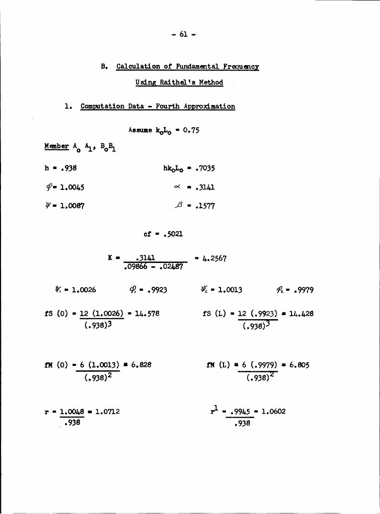
- 61 - IB. Calculation of Fundamental Frgenog
Using Raithe1' Method ~
1. Comggtation Data ··· Fourth Aggrozdmation
Resume k°L° • 0.75Member A° Al, BOBL 3
h ·· .938 hk„L° ·· .7035
Q' 1.00l+S °< • .311+12/’·· 1.0087 ß =· .1577
cf ·· .5021
K • .31l.l ¤ 1..2567.09866 · .02).87
V - 1.0026 Q ·· .9923 Z/{ ·· 1.0013 ß ·· .9979
{S (0) = 12 (1.0026) • lh.578 {S (L) ·· 12 (.9923) = 11+.1.28A (•938)3 (.938)}
{H (0) • 6 (1.0013) * 6.828 {H (L) ¤ 6 (.9979) =• 6.805(.938):2 (.938)2
r • 1.00l.8 • 1.0712 rl- .99L.5 - 1.0602
_ .938 .938

- 62 -
7 i ¤ 13 23 33 A
h - 1 hkOL° • .75
¢·· 1.001.8 °< · 1.001.8 =·· .331.93
ZV' 1.0093 ß *· 1.0093 = .16826
¤f " .5022 K '* .331.9 =· 3.9931.11216 - .02829
W • 1.0031. Q? ·· .9898 TK. - 1.0018 Ä • .9972
rs (0) · 12 (1.0031+) - 12.01.1 ss (L) -= 12 (.9898) - 11.878
ru (0) - 6 (1.0018) - 6.011 ru (1.) · 6 (.9972) = 5.983
p · 1.0061. pl * .9927
Member AGB).,h • 1.125 hk°L° • .81.375
sp- 1.0051. 62 - 1.0051. (1.125) · .33703
(V- 1.0105 ß• 1.125 (1.0105) ·· .1895
6
cf • .5027 K · .3770 - 3.51.99.].1.21 • .0359

.. 63 .. II
Hanbarh
• 1.085 hkoL° - .81375
· ¢=· 1.0052 <>< = 1.125 (1.0052) ·· .19333 (1.95)
Z/= 1.0101 ß =- 1.125 (1.0101) - .0971
6 (1.95)cf - .5023
6 3 K ·= .1933 == 6.9209.03736 · .0091+3
Haber AZBZ ( 6
h • 1.1081 hk°L° 6- .8311
5V =· 1.0053 ¤< = 1.125 (1.0053) · .2693
3 (l.h0)
V - 1.0103 /3 - 1.125 (1.0103) • .13536 6 (1.ao)
cf ·=. 5021. K =· .2693 • 1..9686
7 .0725 - .0183
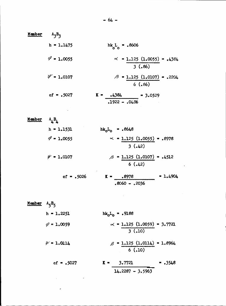
- 5;, -
Mmbecr ABBBh • 1.11.75 hkoLo • .8606
gß ' °< ° 1-•l25"2(.86)
V- 1.0107 ß • 1.125 (1.0107) - .2201.6 (.66)
cf • .5027 K -· .1.381. - 3,0529.1922 - .01.86 ~
Manber' hkolao'¢
- 1.0055 ·>< ·= 1.125 (1.0055) · .89782 (.1+2)
W - 1.0107 ß ==· 1.125 (1.0107) - .1.5126 (.1+2) „
ct · .5026 K - .8978 · 1.1.901+.8060 — .2036
Member ASB5h - 1.2251 hk°L° - .9188
W - 1.0059 «>< - 1.125 (1.0059) - 3.77212 (.10)
W- 1.0111. ,3 - 1.125 (1.0111.) - 1.8961.6 (.10)
cf - .5027 K · 3.7721 * .351+811..2287 —· 3.5963
IJI

51
tv
I' üIN
I
„_‘_III
I
IT
I
IGI
„z'
@4I I
I2
*~I“\I
QIYI‘\ I-1
I‘IT *III‘*
I
I
E ÄI
‘ I
II
I
I
I-•
I
~4
xuW5
I
I_;
I
rg
I
Ä°
I
~=III
I
ä
I
II
•H
I
II
*>
JI <»I
II
••-•
si NI
I
I
Q
I
I G c
M
Ié-. IX?
I3 I—I \I>
TB
BI
YI
I
I
II II I
E
I°1 I1;] I
II
—I·+*
I
II
EI
I I
I
'iä
I5 Ij;
1:
>
II>‘
SI___ \·°’j
1
PI
I
__II
3$4
I
“I ¤¤__I
II?I
l
II
INo
I
I I 32 Ii SQ
qo
a
II I
I I dI—
I
07I 5; I

· 66 -I
Easmxa Zmxzm IJa//1 77 5- K K I
ASAG 3713/ _4.7g7A" 8;
A5 B1 .3546 .64263.793/ _.4787_ I8,34-/0 /_ 0060 13773/ I
E I¥ I
~/wirf 2 /14 .-. 4.4.294-1 1 ߢA+ A5 -***3/ .42/¢ 3 1A4 B4/.4-704-A4
Ä, 3.99317,4766/. äödo 1 3
A ,31
IA2 B" 20527 .2766
3.773///,037//,0060
I4./41 1773/
Al --I
AIAlA
A A *7 5' ‘ ..1*-2*31. .2606
0A A 4 250/ .6261
06601
.___
gtion
IQQ „ 1 - 71-· Mbm
I Q °2
7
g T
I1 ·
I6.
_.
N
'> I
I ¤= 2.* t
va«
1
1_§:^ ~+ N
' I f I ;I‘i
‘
I 2-‘.
°
_é L ·0
I
I :4
ä Z F2GEL 2
I ;<u\ ¤¤ Z
“11·———-__,—: ,- °_»¤_ Q
1
Q< 'Q xt‘ ‘ 9I·=
N, 3‘$
L-
NI
L <_L ° .
I
Lo
_" ~.
I¢Ü
'*7 IL
]‘I '
'O
**7
I I.? Q
2 ,7;*
Ü
I I
~¤ÜI
*1·——~-...;Q_‘
Q I: Ü g Q3 . _ I
I *<-· „,° I ¤ 2 2* I<>
‘
$2 :~ QVI I FF Ii? 7
2 I-1: Q '~
1c~
1 2 .‘
Q
·
Ü 7 <
QM · __ 5 ä Q‘ **' ‘ LL _
w.,
I~ ms gfitgxM
7
7, I
· 7,
I.
f‘*—·7.„Ü__‘Z
L" MIQ71Tw
Q*
Q
L
’°°é"'$.'·L§I7
*‘ä¤ 2
· ~2 Q I·II "I
·<= Q
I
Z ZI22*2I
ß ä\ N Ä (
LL _\ IL < QI
* ****L*LL**
7"‘ I
‘_ _ Q 8 Q 3 QIQ7·
*c¢\· N;L
‘ L ·Ü“ Ngc:
el?‘ .
2 Tä,‘Z‘1l’° „„
L ° IW ‘ ¤¤ 1Q 2
I4 Q-,II·•Q VN
,Q [ ;<: Q
7
I
SL 2I
I—12v:+ ¤¤ Lg;III
°_oc2
I~="' QI ~¤ l’};,—*”«—777777„7·° ‘ IQvv1
gw
QN
LG°
Q N QM ,
iL—*"— L
öIN")
7.
-.._
I° Ü 2 ¤ 2*;,* *1** :IS
LL
H“I <>~ ¤~ Q
~• InI
TI’
l‘ QM ~
—-
nt Q "'? .Ü w
‘ I¢
“ ~*· 7 7.
L ·I ‘ VI L Z ° S ° <> IN Q1
L7 \L °Ü Q
"
LI
L · °. ‘. I: 2* ¤ #4+° · 1 1 2 °. ¤
1*
,L1
,"’—·7-„§ _; Q °_ Q Q SI:
••Ä N.
. Q, Q
QV L — I¤
I ° Q
IQ
2;‘· __—\
._I
3 Q
1 1I
LLIIII,·
tgI
Q I N_ \ °° Q 4•~ w In I
* Ȋ
NI Q;
..l..__~Q.\6<1¤QQ
2:~+j„QQ_;¥<>_ I
Q':
L ‘
I. ~“
xy
-****'**"—,_,°
·—77 --’ WJ
·;"T**=‘¤ÄÜWW
1I* [
viM M
»•T I fI·= WQ
„g ‘ N~• I
-7
‘.?I,„'~¤¤;~I~•~> *·I
·? F FF Ei
·· °. T¤ Ä ¤
*·
I ,· ·° IQ 'gz-|L
L
I-791*;* Q~• CT ;
·1”’ $2*L I
**2-***7;-L-___j•—
OÜ: g
:3L _ LLÜL
LV
L
In M
" *·——7I-' 2**8
Q
*0 N
°‘·Ü··—¢7LL_
.
¤'§
7 ÜÄ
.*3; {Is-«
TLLLL L L*"'1*·*~*
I

'I - 68 ·- Iähm: Ih.: Io. I1;a¤¤l§L;L.m sul Q2lmm.1I‘.l..
A .......,.„../‘£l.,...„. .- Bwlo fi - ·- —~——·—-.-————-———————--I
I
II I, II . II
AQ —·-———-—————-····———~ —-— ~-—.-···-~———-— - -~ ~ B9
I IIA8 I‘N"“°”N"W""’”W""‘W""‘l"‘"""*"‘*“”"‘ ‘*”"—”‘ ***7********7 ·····*‘ · ·* By
III ,006 Ä
A7 I_oo•I
,00/ /-,002.:,003I
.79276092)/0o64(.0¤/)6"""""‘**"'**""*—°*"""""'*"" ‘ ' '*“‘ ‘—‘··*· -•···'*···-———--—————~——'-— -~·—~·——--——I-—·——————-—--——- —;i—..........004- ,77z7(··>04//.006460/2)I
,004 +.043 -Z ,0/6I
I IJ;
.- .•— ~-—l—.....—-,-,.--—.. Z.Z .,--,.,„_ , Z, _, , „ , ______ ," ‘‘I I—-,0/4
+.04-6 Z _066Q .77276446/ /0064(.0/4/
KN.077I.078 #—_z38 = .3/6 II .772760:0) /006¢(°77/ I.2:4 #-.060 Z.:741?’—“i'“°’“""’”"’“W‘W"W’WW‘"‘°°W"‘°‘’‘W W ’ ’ WW B5
Igoéiftr
I .f:4+7,467Zg_06/ ·I .§?27(/#3-8) /.0064/568) I/447 4-, .177 : /788 B 33356 ,§II /577
/2.04/ -7.56,7- ,78¢ = 7670IIII _¢·767(779,I /•06¢(/-ff?) E I\I/I .777 7/ 876 — .773 - /.587 Z 7 676 I 38_/OJ;AI/¤——————·—· -~--—-·———·————·———·———-————--—-—--———··· ··—6—-————·——·————··~——·---—·—--~+—-I B, -———-———a•
I /.5-44 /060z(/:*44) /07/.z(3_037} II /4—_4a6 — /.637 — ,2.2:*3 Z 9, 538 II
I /IA kk 3.0:7 I-
0 __l,_,,-..,..t,.,t_,.i,._..._,.. . .. . 1. Z. ,...--_.,-. , Z. ,Z , _ , , . ..
ßo
Inertia Force gg Column # lÖICI /70/
Ao 16/L -
f, /70//é-/,/lfl. 5;[O3

Fourth Approximation - Moments Due To $2 1 Q
QTQ? T°QQ QQQ QQQQQQ"*””mQQ
Q I Q79 N ¤21***;
-- 1* 1' Qd?QE v+ %~+ wm K "*
I Q Q I. Q Q
I L-;II.:LIIrL-III-I..I.I.I-.I. I °; 2 gvQ QSI1 Qux rx Ä 1N S‘$ ‘ 14. .Q 1Q 1Q ZIQ Q1*Q
Ä :
1 an ~1„.? Q. Q¢~ ¤II1N \‘I W IQ Q M 1
Q °1 , · ON1‘·QN ¤„ QN "IQ oÄQQÄQYZ Q2"§
. 2 « o 11‘ 1°11Q1Q}1Q IQQ Q~ ¥•„ r*=¤ Qo
Ä? Q1 . ·Q N 1Q Q IQ Q IQI Q
.41*; 3 **1 ~> 1;,**7:2}}, 2 o~ 21 Ä, Ä ÜN :1*2 1I , I'
II I Q
I I1I
I' QIII___,,_,, _, ,.I...II..I. .. I II - II1
N N W W I N NQ ÜQGÄE 2 °°¤o Ä °Q:
Q 4 M N Q I. I- 1 4 ¤ ° ¤
NI ¤¤"’
°" ·u N '~• In""ow•¤ v~ .Q·ÜQQÄQ2 vi <‘‘·‘·¤¢ II 1 1 I II I<¤g
xs N 1,, I1,I Q u QQ
III1Q
1* ,' 1’· 1Q °_.. ,.II. I I I- I -- II..,.-.-. I. III . . ,. I I I II I
1 1 \ I I 1 fi.! QQ QS:f14 16 ~I,; I' ' . · I~1*•; I·I¤·j*AI1' 1 K<¤ M N IQ. I. . I.— ' 1 ‘ 1 ' Q ‘ Q1
IN 1 Q i‘· \’ N] 21 1 1Ä?>„; QoIQ IQ Q ‘ ¤· I·1i
I; IA1 1 Qs 1 ;‘ Q ·~11<> 1
M M 1N 2 12 QQ„„Q+Q„, QQQQ[Q- Q] QQQ{< N2 ¤1~<s QQQ QQ Q Q ° x N 0 ‘ _ Q .1 I• IQQ 1
,< Q 2Q NI g N ¤ qI•~N· 1' Q 1Q Q 1QQ ‘Q 1Q
__1lgv ~- ~· °. Yi "¥ . 1
1 · I . - I : 2 1l_ ___ ,III II. ,I I I,II II,. I. .. .. I L I - II.-,L. IIII 1 2 , .
2 1 >¢21
’ Q
I
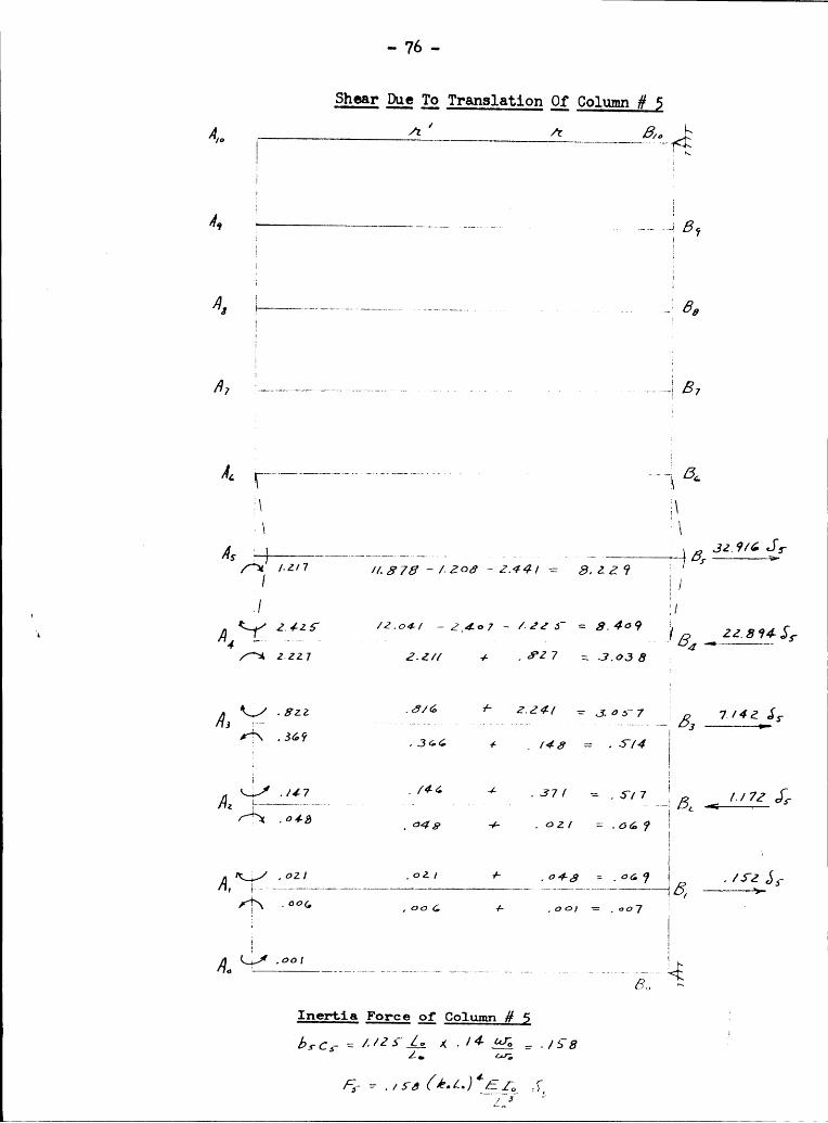
Shaar Dao Tg Translation gi Column # 2 I72 ‘ 7: 6Am ” Uv-- v___”<
T Qll,
II
I,0/o 56.—-·--—-———·--——~·-——·~····— —··· —· —- ···· g ~—-—-————-5»8 .002 ,06; 0 .005 I
. . ..,-----. .-. .. ....- 7 —•(-il-—
#*07 ,007 + ,017 -2 ,026TI
,0,1 .0/9 ,0 .007 :,026 IB ,276 fzA6 ..-....——..-—-—-—-—-—-—-—--i-—-—•—---~-—~------~------—· ~— — --——---—-——61··—· · ·· -··I G ;———->-
.030 _03• 4- _o1z =./ZZ III,671 .07¤ + ·4—5·=' = -/<’°
I 1.176.}:A5 ·——-—~———-—-~~-—·-·———-———·-———··—~ —·· ‘·~··——·—‘—***·*** "‘·" """ •(*l·———_1a.6' _ 164 4 __34,/ = ,4-6.$'
I.231 ·3~*’¢ /- .100 = .4-62 B 66705,· 4——-- -·—·-—· ——-—--—---···-———-—-—--·—— --—~—~··-—·-- 4 —-——l-7
fü .524 4 1. 773 - 2.377 _ iris;)
IA /.782 23.10,9 J;
3 -........2M-.-—-4 --—--- ----— --—-———-—--—~— 3 -<———i—-1.74 4. I .062 JI /2.0**/ · /7—?° ’ ‘ 9/6 = {/73III
_ I_„Z /L878 -,705 -/.9.66 : 9_617B
3ZG38;‘Az · 747 L 7/7%‘ 11.,976 -.712 -/..366 = 7802 I—— — 2*
I12.04/ 2 L3¢$_ -.752 == 0744 [
A /.355 B 23. 5.6*; jlI /-24/ 1. 316 1- . ¢/7 = /. 73.6"
. 37 ” .
A.Incrtia Force gi Column # 2 ’I0. ¢.. = /-/2-YA; ¤< /6/_<·g t /+74 ILo 6;; IFQ : 1474 (é·.z..)‘ ATC AQ IZD.?

Fo111**1
mh
1APPN
*
1*~’;1———===~-111.1
1
¤«’ ~1“°
71-
I..._
MO
1vv
‘1Ö,
"‘——
man
1·=1m1“‘,·.-
6;~1"~
tem
1
8TO1
ä“‘;;1"’ 1 °
1~:‘L‘”
Y1
1*:-_
1
1
7 1 : ·1--
11
"~1 °·N
____l
”"bi
·•,‘ :Q1 '
1
•~ ~•
gß·i 51;
" 1
1
M1·1
°€ 2 Q ~>"
E?1
EO1
1‘
‘
1<:1*+1
’+·._·
°'v
1 ·1
1O1g‘é” 1
2
{
'-._
‘ ' °
H,1
1
1
Ü!
7-*.·
1x
IR
'
'1
?w"'
”°
Z2+1
1
1-1*1;
:1,,
_1<.s,1
*41' -Q
~1• „
1.‘ *.
1 ?"¢1 ;
„
1
q
1
11
,11 = ¤ä‘——- 1-
¤1
5 1,,;1 1
1
114
=1•s1•«=1
*.--
*ow
1 12 · L
ä1
1~1'~1„g „
»-1.1
gw:
: I E1i
1’ ‘1°t
°~— E
.*
11
1m*1-*
¤• ~
1··— '~i ·
1*5*1
1
I11<;1~1~•Z __ "——„_
. 1•~„, 1
_~_1 Fg;
¢ E
.
Q1
°—$··-„_·.1 wä 9
°¤
~'i1v
‘ Q 1
F
1
.1 Q
*• 1;,r-__
’<1 1
„-__1
--__
14
1•„1°‘“·#i_*1 g 1 xi
;—1
’ «
1
°·
12 •~?°$”
·1°‘¥
1
1
v‘°° ~'
"‘
‘
q_
Iü
11h\,«;
11
—
„
N *1„ ·
1‘1
°f•v 1*--*-4
1
1
·
„-„‘ 1< ¤ ·:
~1 1
1~1_‘;+
1w
_;
_
1
¤_°‘·—- 1 · Ä
1: 5 1’ ="1
·"’-„
’
\
·—_.
1— 1
71
SÜ
1***1',;1•1„,
1—___11*% Q1 ä
__ „1«:·
E
_1
1
1
1 '
11
1. qIn
-11
':;_
'·¤Z\91\E"7„,
‘*1%
1—.
1
1¤o‘°•€‘;°
1oäu
1.
1é~..
\‘°·:_|,\
4-*-1,‘
ämÜ
wi
1 1I
1s
.
1
1
1 •
.
1531..Ä.
v' ·Q ¤
1
jr1
11
ggw
11
11„11•«»· ••1“‘—-- 1 ·
%12
1
1
_1
=m1qw;
01
1***wm?
°1"‘~1°-
‘<<‘-‘
°1°
?1+ ¤
‘ *6 -*°‘° ~¤ ··~
°'¥”’·
-1 ¤
·1
‘ _ „1*
1,
1,Y•~«~;
,1
,4:
.
"___1w
g-'-„_~
ß
MQ.1
.<;¢ä ~>
·~"'—„„~
;1~•
,*1- 1 1<2.'V
<g1"·—,_¤ 1 11 1, W.,
;§<
°~Q_•E„°——___1·
_1;)}-1
1 w
€gJ1§·w’
.1°¤‘¤
kg Q·„"··
114
,11'•>i\Q1
°e °
11P"
w‘+
~_•Q10
‘ :1 °
·
wg1E
1_§‘:°,§1§1
"'__;___·°11~ :
f·„’ 1 1 1%;;-31"
~1°S1':
‘
°•~
1o1
” Ä1 ;
’'·
j ·_1
1,- 'i ;.
1°.1
—1#.__1.Z
•~ §_·»‘ T
1,1 ___1__;i__\1
,,1111
1<v1
ä ~ -11*
“°"
;
<>*NI
1
17:-11""1"'1
1”°·—._' °-
3\* ~¤
..
¤Ü‘-— °<• Z1:
‘
:<1~•1'*#=
‘ ~ äw;¤
1
L~—¤•~—·—„
-1¤¤ ~
1;_„_\"Q1
Ä ¤~’“‘· °
"'· 1;
1 ‘ ‘°:"‘;°l’1
¤~”‘..1„.Q•·=°
1
•;';
e
"_--·
•
_ ,
?_—r
_] .v
äg
‘——*
,
'% ~» —„ *1~1
A3
1;
’ <___|1~'§'1„11"·-—-.
°. 8 g ~.-1‘
1 ¤'~„‘—« .1 1· ¤ä ¤
gn,
1
1
·1 ¤•11
1YLN1
”—_
N1
.47
"
.1¤E
V1}!
‘ -_ ' ws
ä
·—
gl
V
1
J°.
s-"-~__§
1·x,&1
1\'°
1"v_:~
1 1 ·.;¤
°~
1_·u
11
1’ 1
“.—~ 2 ,=
3Q 2
i
1,...1
N *1
1 ,1
·~—·+ -0
1‘
1<
*71
*·„_
Q‘• **1
1
„
·.
1
fb,
T ¤WP!
° J? •„ 11111
„··*¥
wi
¤‘ N~
f .j1
1181:1
RE
° "1
16*‘ 2
1~>„*Q‘
Q1
*—
”
'
•“·„Y•
1
_’
*J2V®1~1‘«*2¥—1
1’§‘“11***@
P1j1"’·1—,1_
:1,Y1·f.1‘,gW
~“‘1·7·g:‘1ä
ä*’ö1114
1- 3?·‘§„
1·
„.11„¤1¤;Q
··1;;
~=:·1g
1
_
-’-___
gn I
x
~E
EV
’°Y£1;Lf'
*1*1-7- 1%= 1 1
1‘
’’
*1
1
1

1 ·· 72 ·Shoar Duo 12 Translation 2; Column # Q ·
Aw /2 ’ /6 6.,<E
006 Ä/6, Q----------- - - -6 6, .„3{— _0oZ
.002. .002- 1** .0Od = ,004 ZSA8 Q_______________________________________________________,_s_____1 _,_ ______ ßö - 06 _ 3/Q\ .¤¤6 .003 + .012; 0 ,027
Ä I/ 00,7 .Ö/7_0o5/4]"' 1 ßl
.0¢LQ ?I j .79 hf/I,:E:--.----:---.--..-:- Q. 5, s 7 6 -«Q
J3? -/8* ,4 .556 0 .742 =
I ,_ Q/,•¤,Q_/.534 -¤¢° ,4 .466 :.736 QB 7,4sJs
S' %-K--—-——·--————————·—-—-··—·——-•—— ·————— « —-«-· —~ -—-- -- - - . . . 7 , . 5-. __)
rb -437 ·¢3Z /— 2.202 : 2.634 Q_’/g/j·_>;
64_64/—-•·-~—~--—·-— -• » ~-—-—-—-- ·~—--·—-----•-----• „•. .- . . . .. .. .,. ,...._7.„,_._. 7 ,,,,_ é 3
QQ /Z.d¢[ - 2.40.4*- /./// : 8..62: Q\ __,_·__ 16 6I .I 6 675 - /.066 — 2.4.6* 9 Q Qß 3,03,,8 $3
T7 ‘”3 /1210 -. 726 — /-44/ : /-4 /7 Q - ·i’2‘.;2/
/.63/ /4-0*/ · /4/*7 — -%/7 = 9.483 ‘ ZshljAL
6·__————‘°—°——°——_”°”—_°°_“~_—”””“_“”"—" Q'- 'Q Q'"'"'“"“i"'“"“"‘V 5; "*-‘l****
/.4 59 4 .6/5 = 2.074 6 2 ,062 J,Q
I 6.607 4 /.479: 2.036 ,5 sésssé/I‘\ ·"5 ,/7.3 /-.0531:,2236 6 ** * * "6 I
Q I. 067 Q<§
86
Inadtia Force 2; Column # Qbs cs K . 88;6_ : ,9904, 4/;
4- „6 = . 9904 3 ’

IFourth Approximation — Moments Due To 5+
i:t°l"% ¤'\’ "‘
Z ¢¤ Z- 6 1 Z ·3 ··rg —- e Ny, + ag y, _ '-[ + ‘i2"BJ§’^· “* ä ° IM?. °
F-?•"‘ '; V"-?“"‘T'“" """ "°'“ ‘ T " * s<1: NÄ §“TYNY«§
" :°¤~':Z:~~ *O_‘“"s "‘ ‘' °
§?.§‘¤•~« LE! :·"· g 3 °g 3 4 · „ \ . . ' .| · E Ä,·a....-.4..- .,.,„....,-.,-.. , ,.., . ...4..-.. -.....,.„>.. .. ;_„...,, ,._,, .,7 , ,
j I ;"
I : a .
° ?¤1‘$**;;g§$ :3 [•'l°g:"? sl: Q-¤:‘§:°·~£·¤ ¤ !‘.,§,~••~:;§‘§; o
"‘{Ä o °g ;<! · n 1 , <<KN ~ g
6 ’-„1é"$°° s¤ ¤ °
;'“~ ~>‘|* ;¥:•Q ¤ Q': ¤?_ j?. _. rg Q Q
„, Y, ,, _
3· ";~ e- ¤ ~ ¤ es ¤ Ü" •~ E ?”’ L ° ° ° ° °4 N ~ . . , »¤ N
'° . 9* q M ¤ ¤ o o qs' ° „·.„ ‘.Y „ V
% pqg\*°¤i9 ~ §v~•~¤~Y°, w;¤M, §°; ¤54 ">„Ü;~¤
"
;\,;·<~i?^: <:Z^'>‘? _ .,- I-I \• «
‘ · ”Q'= ' , . .t««¤'8“:·¥ :2%*: 1>„•l*.§ «>¤%°~»~ ; Q; •„\•~5
8%¤
1 „ : \*° Z =” Y? cw :¤
- · 4 ° „ ‘ ‘·
|~ ·
« lv. ‘°w •~ — M « ·v ' A
r~„ 0~ rn •~ ~sN, j .._.,—•~ N '* |.~ ¤ ° ° ¤I ‘ V ° V ’ ¢ ,· ‘ V ‘
·1,....,.- ...,...,..•...__..,_.-,-.,... ..._., ._ .__,,.„....4.,_
..„_ _ ,_„_ ,______i„____;_____ _________;_4_Y_________ __ Y__‘ _ 4E t" N ¤‘¤.‘N. ~>A N o ° °· "*
~• V °. ; M Q •«
:.238 ·=~»~‘I
‘ \, _ _ . |·I _
4 N \Q Q ¤ \ G xl . *1 [ . ,L .
"
• . „—~—-•--~-V—--— M4-— - - Y--.,. .. , ,„ _ ,, _ _
o°¤° °•¢N"‘“°:.;q re, \j ’_ . ,. . . _ _ (NN} "il e _
' . _
· °* °°N n Ä *“ ‘l‘ x! ~9 0
‘\»„\Ü \ °_ • - * ° °
‘° Q \·<4
· ~~ . I‘ l
_ ’• - N ·I,
' ·~ I.
:2'<1*"~&~Y Ü °, Y§ °¤° ‘ 2° ° I"'?
w‘<” ” J ‘
'v' v'
*’ I ‘ "vl I. · ¤° •”
'.»• I — ‘x,,; «°·„%‘« ~» ..,;;\•| ;.§?1‘i;•;,,'„2“3 *3;%;
il:-gsi? : €¤°
$*Q"•Ü*‘*t‘°. bv? °~= 1;·- ·
·•‘¤‘ 2.·~ ‘•»‘
5 Q 5 ¤ ? ‘ ‘4 . IÜ Q; ‘ § “ ‘· ggü "*: 3 Ü ¤ ¤ „ tg „ V„ ;* N„
°
‘ ‘; ?§¢•-„ ~? ° Y °. - ° Ü °. Ä ‘ ‘5 2 T · ·; '° * •‘ • f A ’ ;I '***’—*°l+**'*‘*—‘—‘*"*—"*‘ ‘*‘*·*·***—*"* " ‘·‘ * *·;’ TIB K Ü, °" Q ¤ ¤[ « ¤~@‘91*
_ 1

Shoar Ihe Q2 Translation gi Column # Q-——·~—-··—-·——--——~—-——--———•-—„-—-•-4„..„.i„.......,...„.,__,__,____,,__i_____,____&__ ‘ __ '_> “n_‘—wpQ
I
Q ._o6/ 040 J4
/-TN ·°°·7‘_0d5“ 7* ,0/L ‘:,0/7I
QI.0/2-f-gI—+--——i—-—--—----——-———...-..-..---...„......... .. -. .- . .- -Q 8·°·’7 .637 + .694 :./3/T
I° QI I,072 +.037A7
·—··—————-—~———·--———·—· - ——- --~——-——··-—·-————— -4-•-t-ede ¢
7‘· I
—...—.._.-....,....„-......_.-....,- --..._.,,-,-_,__,____________, ,____ ,____ __ ____ ¢
-702- .8757 + 2.72/ ;3.6/6I
..·Ä
I 2.704 2.634 /· .76ä = 3. 5'92 2Z_89o J-.. ..- --. . --- 4
I 2*704 /2.04-/ — Z.J’6°3 — /.3057 == 7357.3 22.396 56IQ Q ·* — ··· ··II1 I I//373 — /.Z€3 — 2.723 =7667¢. . .. -.-- ...- --- . .-_ _Q Q ,/+7 /-/77 //-873* — /./65 — 2.634 : 5,676 · 57/4JGII *·//2.64/ —- 2,0 5 —/./8.$' :· 85 .,4,/.7:7
/.776 4 .7/4 : 2.470 J6
.747 ·7”"*
^"”° =3-364,4,---. .-.. . . 5, 5 · ,4-337 .237 4 _697 :.334I
{Ü Ü. Ü
*
.095 -075- + .24/ : ,355 I 7¢6lq,Ü‘g......-............--.---.--...--...--. .....-...-- -_--3-__-_._______________QE E ' J;
Q 'OZ6 ·°Z¢? ‘/‘ .667 :.037Q4,
„.. IÄ
. 8 Q Q~6. Ü
Inertia Force gi Column Qb4C4://Z.>f—é9;K·47-_Ü‘%-$,.:,5-27
4Q : . 6'27/Ä2Ä.]Ä-..*372. §_,_
.sZ6
I

Fou
64
1,-_
h
1 1gYs
· 1-A
?1 1 Y
#—ppr
..
~1—-—
°=d
7
ZÄ
‘ _
7**
‘u
I, 1
Gm
11,'§1¤!·1 ~|
1
erxts
11 1 ¤1'g1
~--1
Du
1
1*1*; °1 1
1-
€< “ ,\;‘·i1-„_
··¥~1_
°5
1E-.,
·¤;§1 ~»
1
1 1
*’
-..
N,‘_ Ä
2,‘”""‘-_
,
1-*-- _
‘
'
A'“···1_
.—·
‘l„ ·
· ;b
o
1
14
“· .
1,——_._
- ¤
1
101
1
‘
YP
2~•
E
1 — 1
11<
~f \1 I‘—-„__
1;*ie
j·¤:„T
‘
*-1.
11
|
_._*
°
1
A_1
.
1—1” ~°
1—·gi
1„ ä "·
:o„"···—«1
1 1*;.1G
1 *·1
=<'”·•1_
1
1—?‘1¤€'1~='.;1——-
11*1** Y1 1d
»
1 „¤„T 1 .-1 e 1
131
1\1^%{
—--_
'—~1*• ‘··- ._ 1 ·
11
— -
6»11.-1 _1¤1 *
3-
¢ Q:1,,*·.._ :
1
Ä<
o
9 Q1—i 111
1’i1„,1“·— —1
‘ °1 ‘“·LL-M " ·¤
112
’1»
"‘—
1
I1N
ih1
11*-;,
N•¤ 'Q
1
“-—YZ_ ·° °
_i-j
‘E
2,,: ¤1\äN’——-_" —
‘ ”_————_—*
rxN
114
1
1‘·1--1*1·«
M•«
1=~
11
‘
1
„;1 1
1__
1
1
-_
1-
1
«<1 .
·-
1
Ls 1-“»_
11
‘ _
“—·-
1é
.,_‘1«,1
~-__—_—
Ia Q. M‘·—-V '
‘· __
‘—--_
1:1
1-._‘1 ä' 2
··
1,
--.____i-_ ix
__~>-rr
, - iv x
_
=1
1~ «> 111,1
11":--Ö;
~s'<‘ (-·—11_ · ~ iv
Ä1 * Q
*1 21;;+;
1g»1;_,=>1’Q
T·< Z
,·'§
1 1 1
3
1"11
N1"1
1
11
‘—~.__·° -1: E 1ß
‘···· 1 1g2 1
„
*1
‘1 11 11
11*--,
° -
11,.,11
2+
11 1-
‘'<1^'•„ -
o~*>
-12-
1 Ä?“—-;_
’—
1gg, q ‘i
·—-_„\_ o g
1g‘1·-.___
1 ,
‘ ,
———'1°1·>‘
‘——1‘
1~>"E·
' 1 1 =*1-_1
1* 1g~•· Q
1·l~1
11
11.2
1.,, E„1,1°1Z‘
Ä-<1
~
’
’
11(\l1N1.—°“i—„„
• 'Q-1 1 -
{1 ,
.°·+__1
._
2
1·=:1«,1„,§
*--1-__¤
„, gsm
1 '
1 ßkgq
··-„_
11211*1:1
"‘··»f•· 1
€„ qä •2 -*"‘1,„1
1 1
21 1 1·=1 1
·"11„5‘
"’ 211 ·
11
<11**1-1
—--,°
¤2,1 1
1‘~¤
‘·”*___
1_
1
1f-{Q1
-__·
, -
,(
1
-
1
1 ·0
9,
1 1n-1
?°1—; °
?1; 1
1
11
1„;§
o1«
1*11Q
;„"i,'~g1‘I';g
_°_ 3
21111,
5
1.
"*·--·‘ °4ä
‘i ‘·• *113 1 1
’ 1
1 _
1
.1
-—-—. . 0 ,31
__ ;1
·
—
1
11
1>—..= '
1§§1”‘“·—-„
-1
"
12}::1
1 *1 1:2
“ 1
1
Q E
1”
“ 1' 1
=“·--_
—~ V1
I N,
1 1
,6· -_ 1
51 °
11-_
1
·-__
‘
1Ä :
a1 1-¤
"‘ -*1 „ ·ci
1@*-1-
"‘ —_
1
3 3
1·=1
I-v‘—.__
,fw V
.L "
•°
—
v~
_ °·
v-- ‘—-_
°
‘
l
-4*-* „_
=
°“’·—-
‘·--Ä- 1 ·
2 -
1
—”1 3
11;*-1-
1 1
1
*¤Ö:$>‘·
_‘ „_ <> q·-
1·
xxl-•‘
°
-
'o‘
"
11-
— —I
IShoar Due _T_g Translation Q; Column # Q Ä
A'“ -2‘
A, Ä—._..__.____.._._...._:-..„-. .-.-...-..... . I .. ..-I- B,
Ä Ägg
{E
. 0 -:-Ü 6Ä; ‘
2* 2*Y Ä I Ä JI 2 * ,32.9/6 ,-.. .- - -:8.229/
ÄY.1 §/°,A grz 2.42; /2-04/ — 3.407 7 ’·‘”‘° °_ = 0·4°9 /5 22.8945,-Ä Q rv, Q v _ . —- -- l,,_.,,l__,..-4 " " 4/'¤ 2.227 2.2// + .527 = 3.038
ÄÄ xy jl, 676 + Z.Z¢/ : 30:7 7./42 5,-
3Eur, _ _ _ Y Y Y Y YY_ _,_ Y Y , . .. 2 . . .. .. - - - —— ~ —--I
3 -—-il-—-•}-50* ,366 4 _ /4.6 = . 5/4 ÄÄ ÄA A/./47 -/*0 * -37/ = .5/7 /./72,,ß-
z I www {Ä { — { { Ä {Ä w—Ä L-0*8 _d4g -.4- .02/ :.66,7 Ä? Ää I R,02./ 7-,067I
Y- _ mh- ·,______•_________ _______ __________________-. ......-:—... —-- -:-----1I I
..-...„-——-„-Q.,
-006 ,084 4- ,00/ = .¤07
,0o|
-,InertiaForce gi Column # Q {/,,C,.://25;: »< -/4103 :./56 ‘
2, 6-4;
FQ- = ,/56 ÜMJEYQ3 ”
Wu
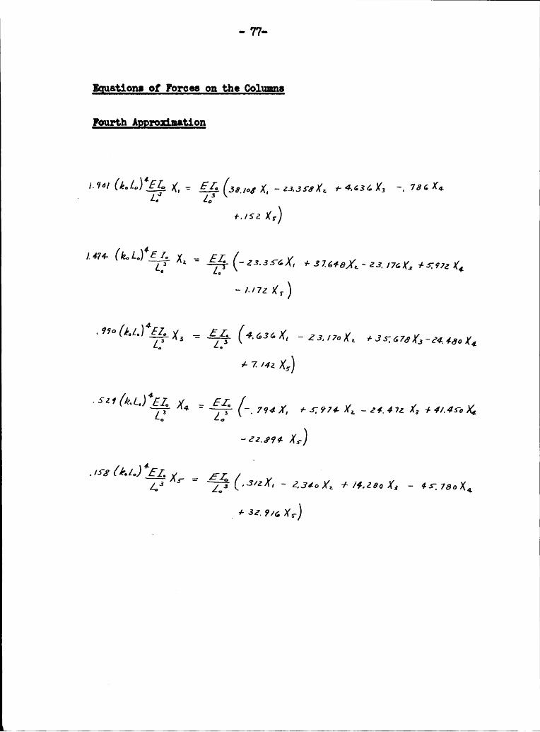
gatioru et Fcrces ou the Coluxms
geurth Aggrczimatiozx
Z EL 1-4.636 Y1 ‘. 78cX*
+„/SZ X5')
1. 11.,1., *6 1.. -474- X, +31448)/,-2:, 176X, +417972 X4— 1.172 X,)
M 1.1. *62... ..+7141 X5)
.511 X4 (i 794Ä +67921 X, -11.411 X,
X5-)
- 4-_'43+/4.266 X, — 451 75oX4
_+ 32.914 X,)
1
I
Ou I4%
I
PI „ 3:
I¢~ -vv N '¤ v'Ü-! '2 I N 6 II I Ni
N'}
P6 N g E Q "I$2 C Y I- 5 S
. IG rl °L-, K
I I M Y MY I I1,I, N
II
P"\I
2 3°“. {P ¤ «>3 R ‘ Y E 5*Q
‘.vÄ} 6 N
I ~.N
"* =< .
·
O·\.u v-,
6 " R
§ ,. XR 6· 6 R .s-46- ~
‘
5 N° Km0
P° · °
Q II°° N v 6 ·•->In I: I~ ov; ä Ü
N) y\
' . q- . Q, x.: _\NH3 N M ~ N
äqq
§\
M Q- vu LI 1 gw 6 °¤N
ä N xs , E N}I q; \J -
Q"}Is
u HE
„ „1 Q.
6‘* °‘
in9
”‘
ä 2 8~ ¤
E * ß‘ 6·•->
I $2 3 6 '°g ¤¤ eviY°
~Y .
g | I • Q
M 0\„/
I
I

- 78 A — Ä
D6 /Cf/77}/7ä/7 fv 6
~ 4( 22 2 2IZ : · - · -· -G .
0 2
4 .7- 7 --. . . _ _' l {Ä
IQ
‘.
3* 6 Ä Ä Ü+— 36 ·‘E 0 »~————»—————7—--7-7- ------- V..;--.--....-..-..-.-.-..,.... . ________,
2 3 ä Q i 3.2 ° L ÜYU Ä YQ 2 Ä Ä
- 4 -7 7 ---- .- .. Y _
2 o2 2 Ü .
-8 ‘ ' ‘ iÄ j 2 Ä Ü
2 2 x# Ä i-2; 7l. Q
6 ~2¤ .+0 .4,0 .80+(222)

... 79.,I
„* F-T¤b1a 1. Ygu¢•g_g£;_•1;_g__1{
E 2 2 IH 2 20.00 1.0000 1.0000 2.62 1.571.8 2.13051.00 1.0061. 1.0121. · 2.61. 1.6101 2.2001.1.10 1.0091. 1.0183 2.66 1.61.81. 2,26581.20 1.0135 1.0261 2.68 1.6902 2.35921.30 1.0187 1.0302 2.70 1.7358 2.hh971.60 1.025h 1.0h92 2.72 1.7859 2.5h931.50 1.0339 1.0657 2.7k 1.8hll 2.65891.60 1.0358 1.0865 2.76 1.9022 2.78061.70 1.0579 1.1125 2.78 1.9703 2.91601.80 1.07h6 1.1Ak9 2.80 2.0h65 3.06761.90 1.0953 1.185k 2.82 2.1323 3.238h2.00 1.1212 1.2360 2.8h 2.2296 3.k3232.05 1.1366 1.2661 2.86 2.3h09 3.65h22.10 1.1538 1.2997 2.88 2.&695 3.910k2.15 1.1732 1.3377 2.90 2.6196 h.20962.20 1.1950 1.3807 2.92 2.7969 k.56352.25 1.2199 1.h29k 2.9h 3.020h 5.00592.30„ 1.2h81 1.k8&9 2.96 3.2695 5.58662.35 1.280h 1.5A86 2.98 3.5938 6.15k62.h0 1.3177 1.6219 3.00 h.0100 6.98632.B5 1.3608 1.7071 3.02 A.5638 8.121k. 2.50 1.h113 1.8068 3.0b $.3660 9.63662.52 1.h339 1.8582 3.06 6.k871 11.93722.5h 1.A582 1.8995 3.08 8.3861 15.73512.56 1.k850 1.9509 3.10 9.8877 18.7Alk2.58 1.5122 2.0063 3.12 22.71.00 1.1..1.5082.60 1.5h23 2.0659 ir ¤¤ oO
·¤ Ra1th•1, A., '*La mnaniaa Du Sistni S¤11da1i ,Hate. I, Giomale Äo 011116, V. 90, 1952,p 630

• 89 .,
·¤·Table 2, Values gg g_;_agg_ gs-
H IE # «¤0,00 1,0000 1,0000 1,50 0,8818 1,10l,l0,50 0,9986 1,0012 1,55 0,86h2 1,11960,60 0,9971 1,00h7 1,60 0,8h&6 1,13700,70 0,99h6 1,00k7 1,65 0,8227 1,15660,80 0,9908 1,0080 1,70 0,7982 1,178l+0,90 0,9853 1,0128 1,75 0,7710 p 1,20291,00 0,9776 1,0196 1,80 0,7l+09 1,23001,10 0,9670 1,0289 1,85 0,7067 1,26001,20 0,9530 1,0h12 1,90 0,6689 1,29h61,30 0,9283 1,0573 1,95 0,6267 1,3325l,h0 0,911h 1,0779 2,00 0,5797 1,375h
*R•.1.th•1, A,, La Dei. Sietaui Soladali,Note II, Mo e Genie Civile, V, 90, 1952, p, 717-18
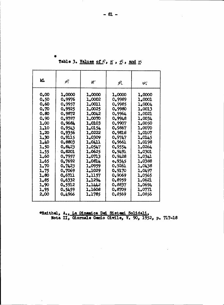
ÜÜÜ · 81 - Ü
e 1‘¤1>1• 3• ........V¤1'111=8¤ $$..8, 18, ß, ;.•¤£ Z1
8 0,00 1,0000 1,0000 1,0000 1,00000,50 0,9976 1,0002 0,9989 1,00010,60 0,9957 1,0011 0,9985 1,000h0,70 0,9925 1,0025 0,9980 1,0013
1,00 0,968k 1,0103 0,9907 Ü 1,00501,10 0,95h3 1,015k 0,9867 1,00701,20 0,9356 1,0222 0,9818 1,01071,30 0,9115 1,0309 0,97k7 1,01k51,1,0 0,8803 1,01,11 0,9661 1,01981,50 0,8&23 1,05L7 0,9551 1,026h1,55 8 0,8201 1,0625 0,9h91 1,03011,60 0,7957 1,0713 0,9h28 1,03hl1,65 0,7692 1,081k ¤,93h5 1,03881,70 0,7h23 1,0959 0,9261 1,0h381,75 0,7069 1,1029 0,9170 1,0h971,80 0,6711 1,1157 0,9069 1,05651,85 0,6332 1,129h 0,8959 1,0621
. 1,90 0,5912 l,1hL2 0,8837 1,069h1,95 0,5h59 1,1608 0,8709 1,07712,00 0,h966 1,1785 0,8569 1,0856
*Ra1t.h61, A,, La Dinanica Dcd, Sistm 86116611Hota II, Gioäe G¤¤16 01v116, V, 90, 1952, p, 717-18


