
1
OFDM and DVB-T presentation, Imed Ben Dhaou and Laszlo Horvath, KTH, ESDLab, 4. March 1999
Performance analysis and low power VLSI implementation ofDVB-T receiver
Imed Ben Dhaou and Laszlo Horvath
Electronic System Design Laboratory, Dept. Of Electronics
KTH-Electrum, Electrum-229
Royal Institute of Technology
S-164 40, Kista
E-mail: imed,[email protected]
http://www.ele.kth.se/~imed/%7Eimed/PCC/ofdm2.pdf

2
OFDM and DVB-T presentation, Imed Ben Dhaou and Laszlo Horvath, KTH, ESDLab, 4. March 1999
Presentation outline
• Introduction to WLAN
• Relation Between WLAN and OSI
• 802.11 MAC and Physical Layer:Current status
• Future Challenges for designing high-data rate WLAN in the ISM band (5GHZ)
• High Data Rate WLAN in the ISM band: ESDLAB vision
• Overview of OFDM
• Efficient signalling techniques over dispersive channels
• Characteristics of the OFDM for DVB-T
• ESDLab proposal for WLAN PHY layer.
• How to achieve longer-battery life for WLAN high data-rate?
3
OFDM and DVB-T presentation, Imed Ben Dhaou and Laszlo Horvath, KTH, ESDLab, 4. March 1999
Presentation outline (part 2)
• DVB-T system description
• DVB-T transmitter overview
• DVB-T receiver overview
• Design Flow
• Improving the initial design in terms of area and power consumption.
• Hardware implementations:
• Demapper
• Symbol / Bit deinterleaver
• Depuncturer
• VLSI implementation and performance analysis
4
OFDM and DVB-T presentation, Imed Ben Dhaou and Laszlo Horvath, KTH, ESDLab, 4. March 1999
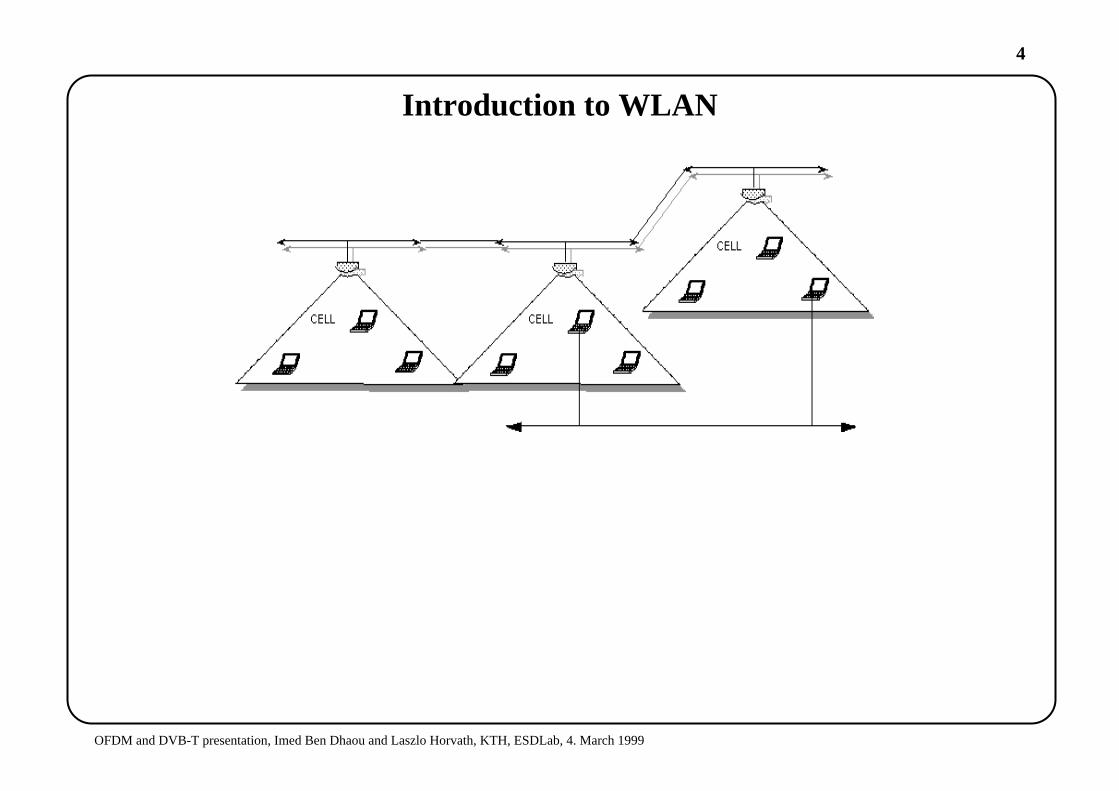
Introduction to WLAN
5
OFDM and DVB-T presentation, Imed Ben Dhaou and Laszlo Horvath, KTH, ESDLab, 4. March 1999
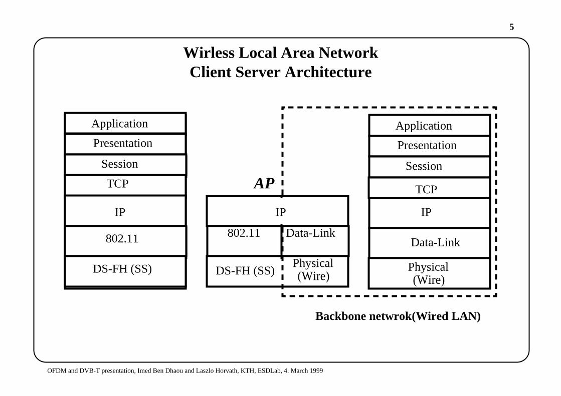
Wirless Local Area NetworkClient Server Architecture
Application
Presentation
Session
TCP
IP
802.11
DS-FH (SS)
Application
Presentation
Session
TCP
IP
Backbone netwrok(Wired LAN)
IP
802.11
DS-FH (SS)
Data-LinkData-Link
Physical(Wire)
Physical(Wire)
AP
Application
Presentation
Session
TCP
IP
802.11
DS-FH (SS)
6
OFDM and DVB-T presentation, Imed Ben Dhaou and Laszlo Horvath, KTH, ESDLab, 4. March 1999
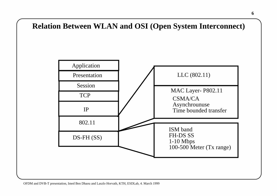
Relation Between WLAN and OSI (Open System Interconnect)
Application
Presentation
Session
TCP
IP
802.11
DS-FH (SS)
LLC (802.11)
MAC Layer- P802.11CSMA/CAAsynchrounuseTime bounded transfer
ISM bandFH-DS SS1-10 Mbps100-500 Meter (Tx range)
7
OFDM and DVB-T presentation, Imed Ben Dhaou and Laszlo Horvath, KTH, ESDLab, 4. March 1999
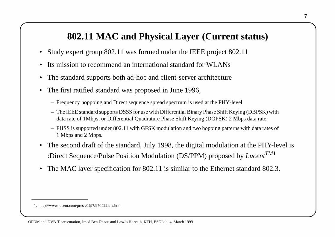
802.11 MAC and Physical Layer (Current status)
• Study expert group 802.11 was formed under the IEEE project 802.11
• Its mission to recommend an international standard for WLANs
• The standard supports both ad-hoc and client-server architecture
• The first ratified standard was proposed in June 1996,
– Frequency hoppoing and Direct sequence spread spectrum is used at the PHY-level
– The IEEE standard supports DSSS for use with Differential Binary Phase Shift Keying (DBPSK) withdata rate of 1Mbps, or Differential Quadrature Phase Shift Keying (DQPSK) 2 Mbps data rate.
– FHSS is supported under 802.11 with GFSK modulation and two hopping patterns with data rates of1 Mbps and 2 Mbps.
• The second draft of the standard, July 1998, the digital modulation at the PHY-level is
:Direct Sequence/Pulse Position Modulation (DS/PPM) proposed byLucentTM1
• The MAC layer specification for 802.11 is similar to the Ethernet standard 802.3.
1. http://www.lucent.com/press/0497/970422.bla.html

8
OFDM and DVB-T presentation, Imed Ben Dhaou and Laszlo Horvath, KTH, ESDLab, 4. March 1999
Future Challenges for designing high-data rate WLAN in the ISMband (5GHZ)
9
OFDM and DVB-T presentation, Imed Ben Dhaou and Laszlo Horvath, KTH, ESDLab, 4. March 1999
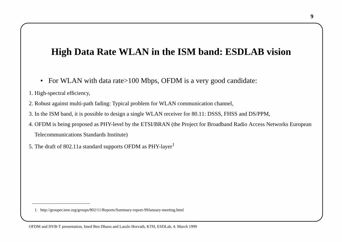
High Data Rate WLAN in the ISM band: ESDLAB vision
• For WLAN with data rate>100 Mbps, OFDM is a very good candidate:
1. High-spectral efficiency,
2. Robust against multi-path fading: Typical problem for WLAN communication channel,
3. In the ISM band, it is possible to design a single WLAN receiver for 80.11: DSSS, FHSS and DS/PPM,
4. OFDM is being proposed as PHY-level by the ETSI/BRAN (the Project for Broadband Radio Access Networks European
Telecommunications Standards Institute)
5. The draft of 802.11a standard supports OFDM as PHY-layer1
1. http://grouper.ieee.org/groups/802/11/Reports/Summary-report-99January-meeting.html
10
OFDM and DVB-T presentation, Imed Ben Dhaou and Laszlo Horvath, KTH, ESDLab, 4. March 1999
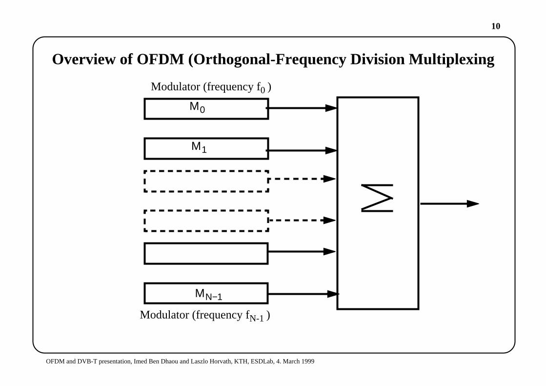
Overview of OFDM (Orthogonal-Frequency Division Multiplexing
Μ0
Μ1
ΜΝ−1
Modulator (frequency f0 )
Modulator (frequency fN-1 )
11
OFDM and DVB-T presentation, Imed Ben Dhaou and Laszlo Horvath, KTH, ESDLab, 4. March 1999
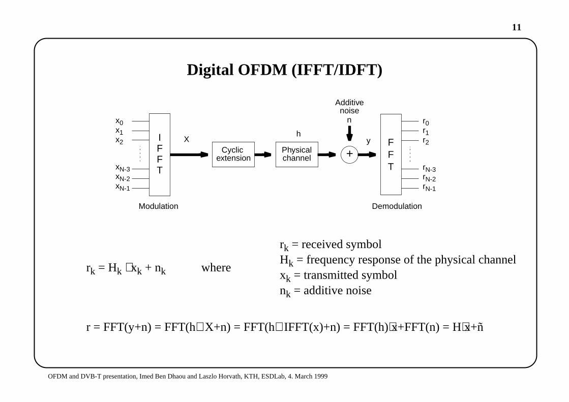
Digital OFDM (IFFT/IDFT)
rk = Hk ⋅ xk + nk where
r = FFT(y+n) = FFT(h⊗X+n) = FFT(h⊗IFFT(x)+n) = FFT(h)⋅x+FFT(n) = H⋅x+ñ
x0x1x2
xN-3xN-2xN-1
IFFT
Cyclicextension
Physicalchannel +
FFT
r0r1r2
rN-3rN-2rN-1
Xh
y
n
Additivenoise
Modulation Demodulation
rk = received symbolHk = frequency response of the physical channelxk = transmitted symbolnk = additive noise

12
OFDM and DVB-T presentation, Imed Ben Dhaou and Laszlo Horvath, KTH, ESDLab, 4. March 1999
What are the problems when using OFDM digital modulation?
• ICI (Inter-channel Interference): Also called: Cross-talk, meaning: interference betweensymbol in adjacent frequencies.
• ISI sometimes called IFI (Inter-frame Interference), caused by the interference of succes-sive OFDM frames.
• Highly vulnerable to synchronization errors and frequency offsets
• Highly vulnerable to the non-linearity of the PAs (in the RF analog front end).

13
OFDM and DVB-T presentation, Imed Ben Dhaou and Laszlo Horvath, KTH, ESDLab, 4. March 1999
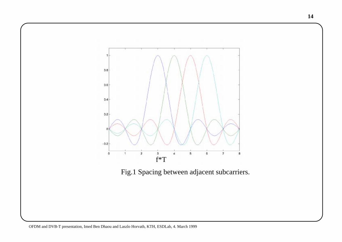
Efficient signalling techniques over dispersive channels
• Spacing between adjacent sub-carriers is ensured by 1/T. T is the duration of the OFDMframe,
• Use pulse shaping signals in time domain to preserve orthogonality.
14
OFDM and DVB-T presentation, Imed Ben Dhaou and Laszlo Horvath, KTH, ESDLab, 4. March 1999
Fig.1 Spacing between adjacent subcarriers.
f*T
15
OFDM and DVB-T presentation, Imed Ben Dhaou and Laszlo Horvath, KTH, ESDLab, 4. March 1999
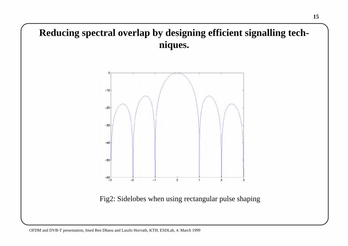
Reducing spectral overlap by designing efficient signalling tech-niques.
Fig2: Sidelobes when using rectangular pulse shaping
16
OFDM and DVB-T presentation, Imed Ben Dhaou and Laszlo Horvath, KTH, ESDLab, 4. March 1999
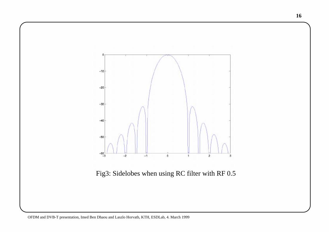
Fig3: Sidelobes when using RC filter with RF 0.5
17
OFDM and DVB-T presentation, Imed Ben Dhaou and Laszlo Horvath, KTH, ESDLab, 4. March 1999
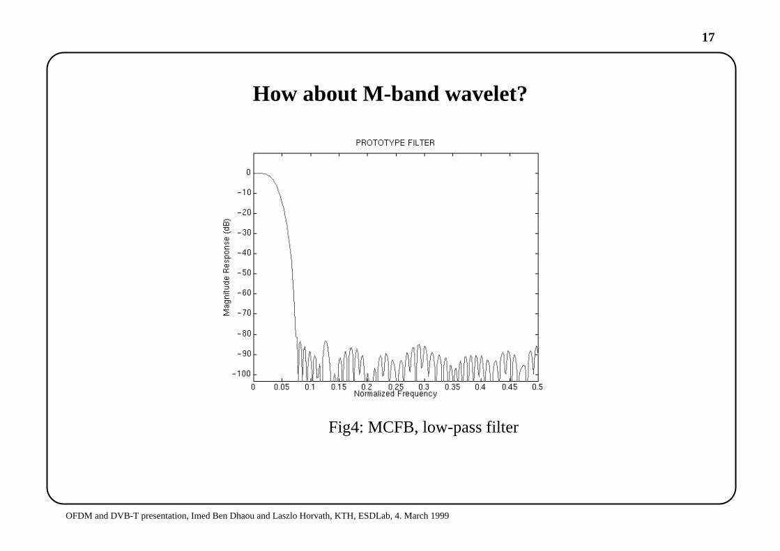
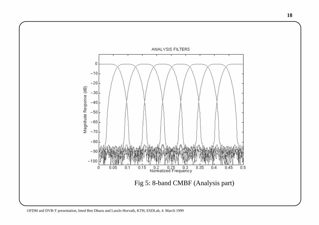
How about M-band wavelet?
Fig4: MCFB, low-pass filter
18
OFDM and DVB-T presentation, Imed Ben Dhaou and Laszlo Horvath, KTH, ESDLab, 4. March 1999
Fig 5: 8-band CMBF (Analysis part)
19
OFDM and DVB-T presentation, Imed Ben Dhaou and Laszlo Horvath, KTH, ESDLab, 4. March 1999
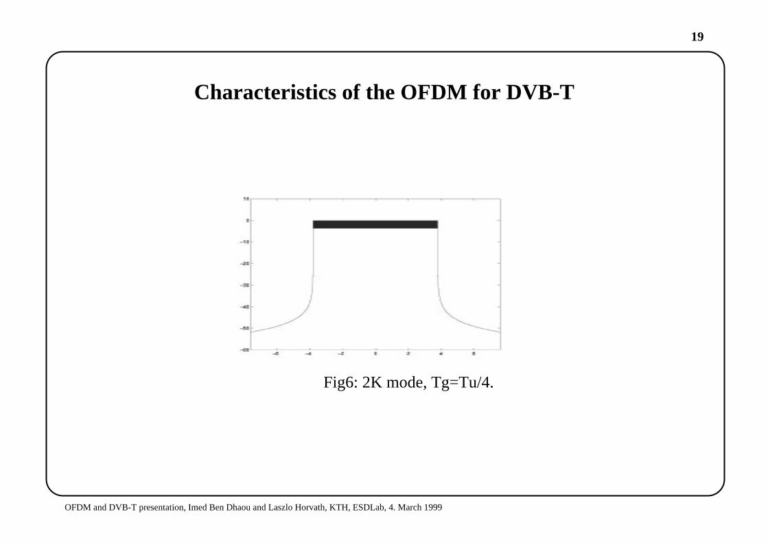
Characteristics of the OFDM for DVB-T
Fig6: 2K mode, Tg=Tu/4.
20
OFDM and DVB-T presentation, Imed Ben Dhaou and Laszlo Horvath, KTH, ESDLab, 4. March 1999
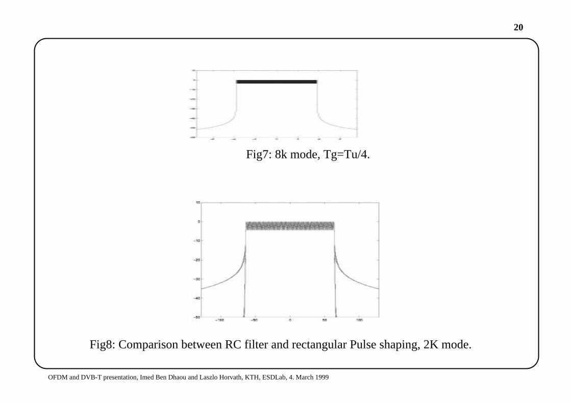
Fig8: Comparison between RC filter and rectangular Pulse shaping, 2K mode.
Fig7: 8k mode, Tg=Tu/4.
21
OFDM and DVB-T presentation, Imed Ben Dhaou and Laszlo Horvath, KTH, ESDLab, 4. March 1999
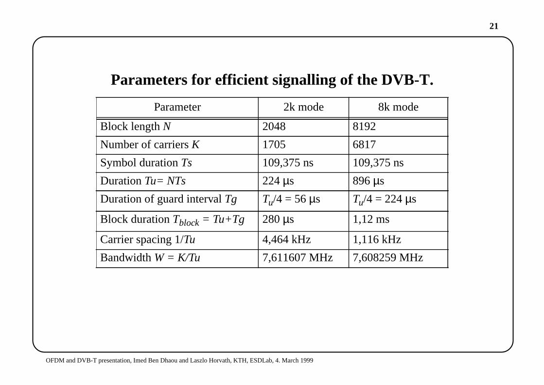
Parameters for efficient signalling of the DVB-T.
Parameter 2k mode 8k mode
Block lengthN 2048 8192
Number of carriersK 1705 6817
Symbol durationTs 109,375 ns 109,375 ns
DurationTu= NTs 224 µs 896µs
Duration of guard intervalTg Tu/4 = 56µs Tu/4 = 224µs
Block durationTblock = Tu+Tg 280µs 1,12 ms
Carrier spacing 1/Tu 4,464 kHz 1,116 kHz
BandwidthW = K/Tu 7,611607 MHz 7,608259 MHz
22
OFDM and DVB-T presentation, Imed Ben Dhaou and Laszlo Horvath, KTH, ESDLab, 4. March 1999
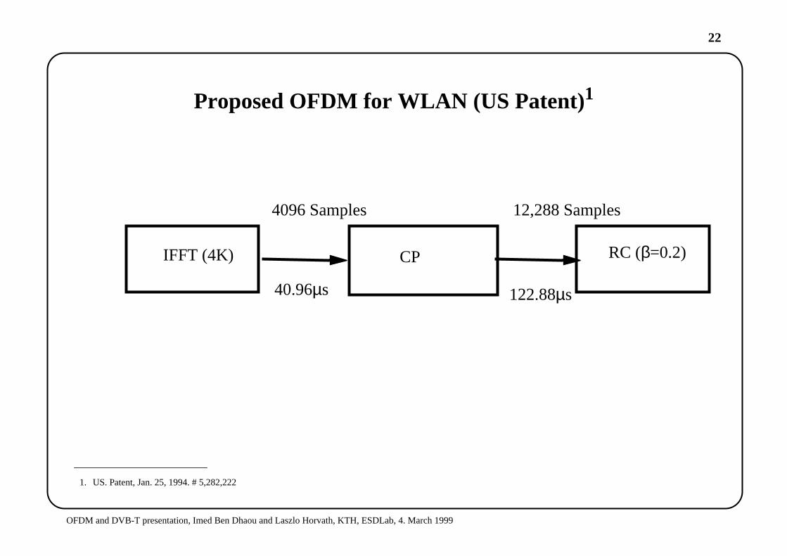
Proposed OFDM for WLAN (US Patent)1
1. US. Patent, Jan. 25, 1994. # 5,282,222
IFFT (4K) CP RC (β=0.2)
40.96µs 122.88µs
12,288 Samples4096 Samples

23
OFDM and DVB-T presentation, Imed Ben Dhaou and Laszlo Horvath, KTH, ESDLab, 4. March 1999
ESDLab proposal (not yet finalized!)1
• Mband wavelet with 128 at 5GHZ, data-rate: 150 Mbit/sec, using array processorat the PHY-level. Pico cells of range 50m. Supports both ad-hoc and client-servernetwork.
1. Proposed by: Ben Dhaou Imed, e-mail: [email protected], http://www.ele.kth.se/~imed
24
OFDM and DVB-T presentation, Imed Ben Dhaou and Laszlo Horvath, KTH, ESDLab, 4. March 1999
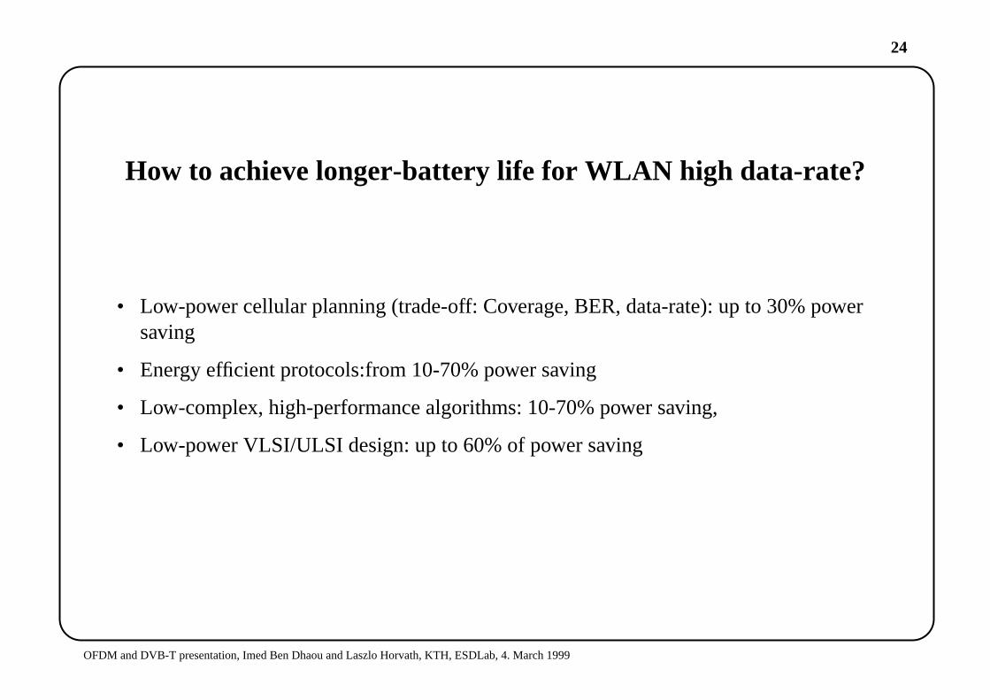
How to achieve longer-battery life for WLAN high data-rate?
• Low-power cellular planning (trade-off: Coverage, BER, data-rate): up to 30% powersaving
• Energy efficient protocols:from 10-70% power saving
• Low-complex, high-performance algorithms: 10-70% power saving,
• Low-power VLSI/ULSI design: up to 60% of power saving
25
OFDM and DVB-T presentation, Imed Ben Dhaou and Laszlo Horvath, KTH, ESDLab, 4. March 1999
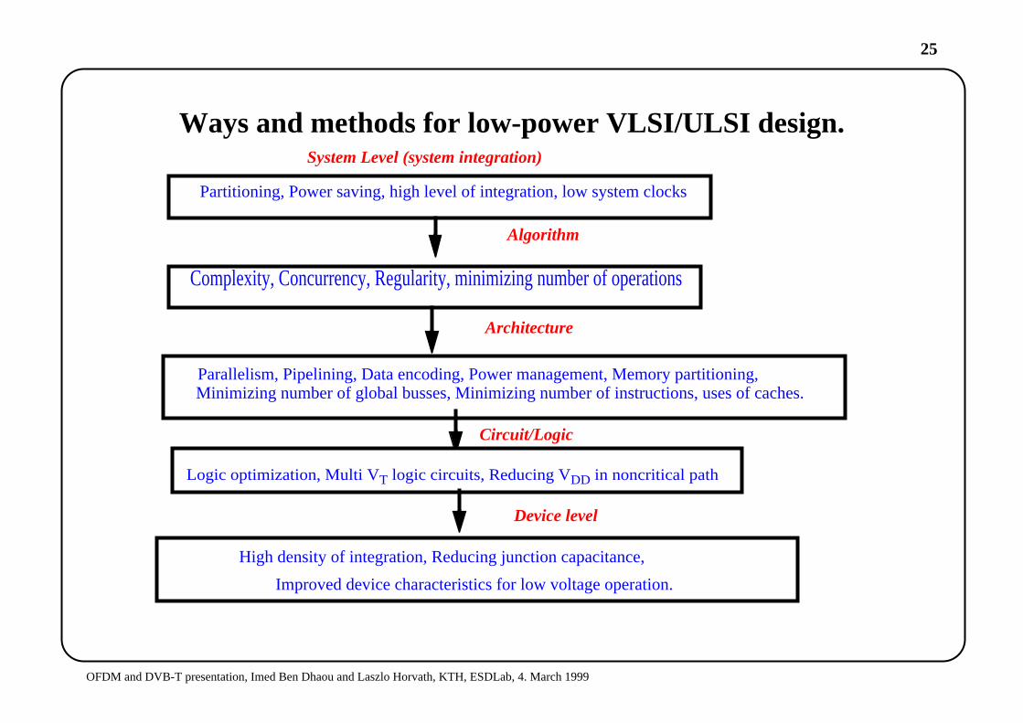
Ways and methods for low-power VLSI/ULSI design.
Partitioning, Power saving, high level of integration, low system clocks
System Level (system integration)
Algorithm
Complexity, Concurrency, Regularity, minimizing number of operations
Architecture
Parallelism, Pipelining, Data encoding, Power management, Memory partitioning,Minimizing number of global busses, Minimizing number of instructions, uses of caches.
Circuit/Logic
Logic optimization, Multi VT logic circuits, Reducing VDD in noncritical path
TechnologyHigh density of integration, Reducing junction capacitance,
Improved device characteristics for low voltage operation.
Device level
26
OFDM and DVB-T presentation, Imed Ben Dhaou and Laszlo Horvath, KTH, ESDLab, 4. March 1999
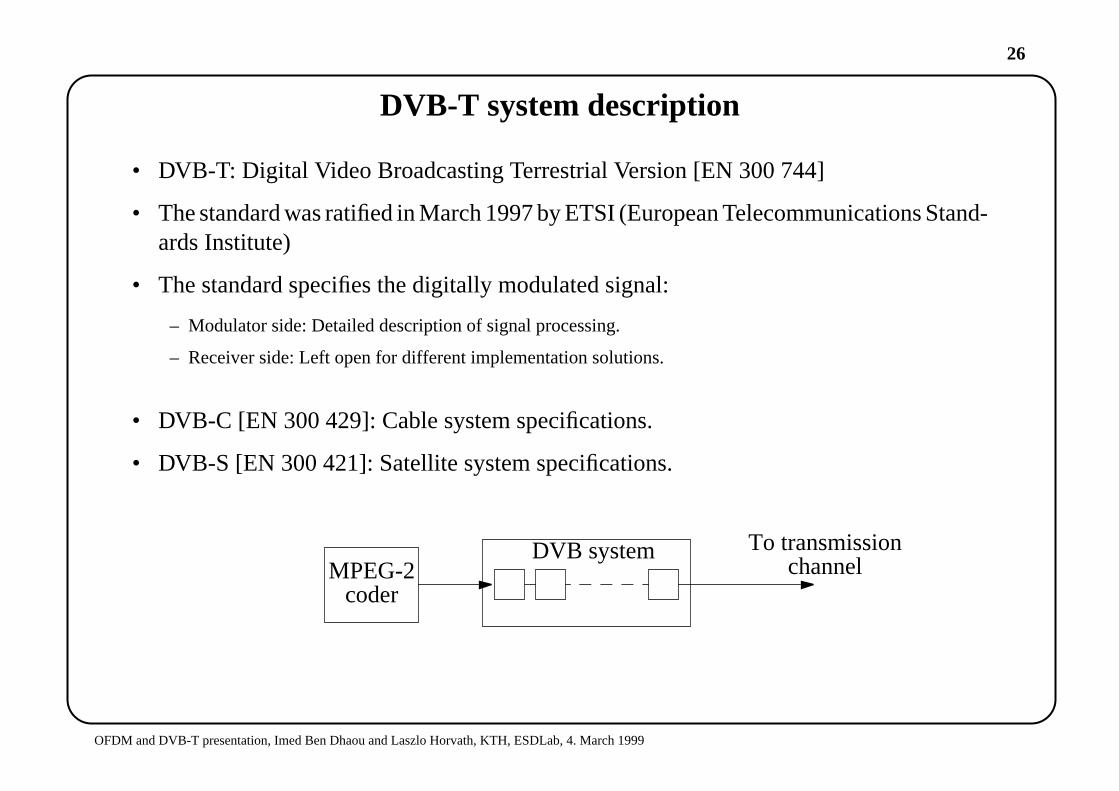
DVB-T system description
• DVB-T: Digital Video Broadcasting Terrestrial Version [EN 300 744]
• The standard was ratified in March 1997 by ETSI (European Telecommunications Stand-ards Institute)
• The standard specifies the digitally modulated signal:
– Modulator side: Detailed description of signal processing.
– Receiver side: Left open for different implementation solutions.
• DVB-C [EN 300 429]: Cable system specifications.
• DVB-S [EN 300 421]: Satellite system specifications.
MPEG-2coder
DVB system To transmissionchannel
27
OFDM and DVB-T presentation, Imed Ben Dhaou and Laszlo Horvath, KTH, ESDLab, 4. March 1999
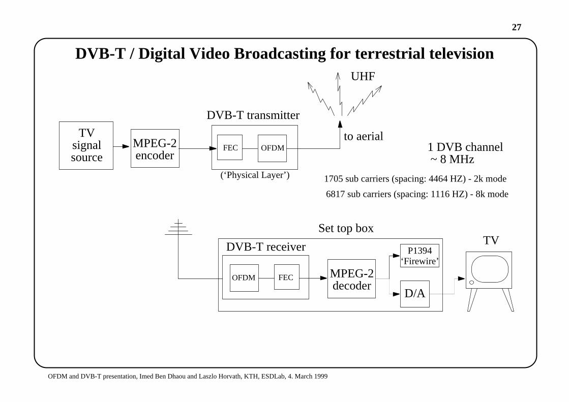
DVB-T / Digital Video Broadcasting for terrestrial television
MPEG-2encoder
to aerialOFDMFEC
DVB-T transmitter
OFDM FEC MPEG-2decoder
DVB-T receiver
D/A
Set top boxTV
TVsignalsource
UHF
1 DVB channel ~ 8 MHz
1705 sub carriers (spacing: 4464 HZ) - 2k mode
6817 sub carriers (spacing: 1116 HZ) - 8k mode
(‘Physical Layer’)
P1394‘Firewire’

28
OFDM and DVB-T presentation, Imed Ben Dhaou and Laszlo Horvath, KTH, ESDLab, 4. March 1999
DVB-T system description
• The system will have to operate within the existing UHF spectrum allocated for analoguetransmissions which means that its required to have:
– Sufficient protection against high levels of Co-channel interference (CCI)
– Sufficient protection against Adjacent-Channel Interference (ACI): Interference caused when two ormore channels are placed in frequency bands that are too close together on the spectrum.
• Also the system is required to use the UHF-bands with maximum spectral efficiency, thiscan be achieved by utilizing Single Frequency Network (SFN) operation. (In SingleFrequency Networks transmitters may use identical frequencies if they transmit abso-lutely identical data containers.)
• To achieve these requirements an OFDM system with concatenated error correcting cod-ing is used for transmission (COFDM).
29
OFDM and DVB-T presentation, Imed Ben Dhaou and Laszlo Horvath, KTH, ESDLab, 4. March 1999
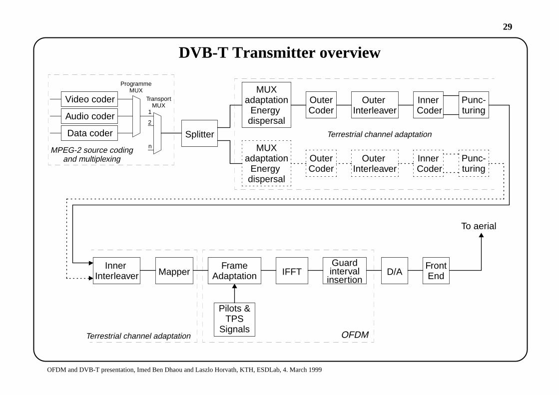
DVB-T Transmitter overview
D/AFrontEnd
Pilots &TPS
Signals
Video coder
Audio coder
Data coder
1
n
2
ProgrammeMUX
TransportMUX
MPEG-2 source codingand multiplexing
Splitter
MUXadaptation
Energydispersal
OuterCoder
OuterInterleaver
InnerCoder
MUXadaptation
Energydispersal
OuterCoder
OuterInterleaver
InnerInterleaver Mapper
FrameAdaptation IFFT
Guardinterval
insertion
InnerCoder
Punc-turing
Punc-turing
To aerial
OFDM
Terrestrial channel adaptation
Terrestrial channel adaptation
30
OFDM and DVB-T presentation, Imed Ben Dhaou and Laszlo Horvath, KTH, ESDLab, 4. March 1999
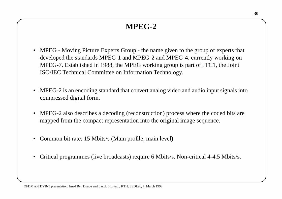
MPEG-2
• MPEG - Moving Picture Experts Group - the name given to the group of experts thatdeveloped the standards MPEG-1 and MPEG-2 and MPEG-4, currently working onMPEG-7. Established in 1988, the MPEG working group is part of JTC1, the JointISO/IEC Technical Committee on Information Technology.
• MPEG-2 is an encoding standard that convert analog video and audio input signals intocompressed digital form.
• MPEG-2 also describes a decoding (reconstruction) process where the coded bits aremapped from the compact representation into the original image sequence.
• Common bit rate: 15 Mbits/s (Main profile, main level)
• Critical programmes (live broadcasts) require 6 Mbits/s. Non-critical 4-4.5 Mbits/s.

31
OFDM and DVB-T presentation, Imed Ben Dhaou and Laszlo Horvath, KTH, ESDLab, 4. March 1999
MPEG-2 Elementary and Transport streams
• Audio and video are compressed to form ES (elementary streams).
• The ES are then used to form PES (packetized elementary streams)
• which are further packetized to form TS (transport streams).
Videoencoder
Privatedata
Audioencoder
DataStream
VideoElementary
Stream
AudioElementary
Stream
Application Dependent
Mul
tiple
x(E
S to
PE
S to
TP
)
Transport
Dem
ultip
lex
Videodecoder
Privatedata
Audiodecoder
Specified by Standards
32
OFDM and DVB-T presentation, Imed Ben Dhaou and Laszlo Horvath, KTH, ESDLab, 4. March 1999
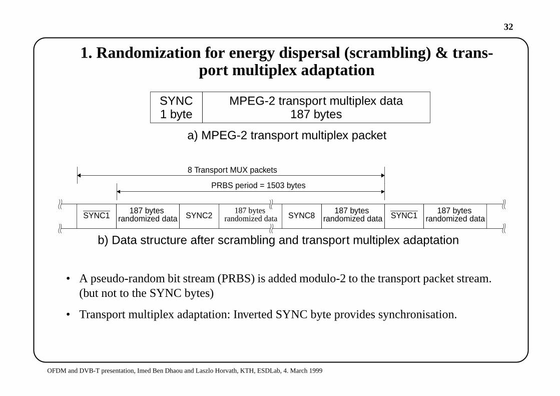
1. Randomization for energy dispersal (scrambling) & trans-port multiplex adaptation
• A pseudo-random bit stream (PRBS) is added modulo-2 to the transport packet stream.(but not to the SYNC bytes)
• Transport multiplex adaptation: Inverted SYNC byte provides synchronisation.
MPEG-2 transport multiplex dataSYNC1 byte 187 bytes
a) MPEG-2 transport multiplex packet
SYNC1187 bytes
randomized data SYNC2187 bytes
randomized data SYNC8187 bytes
randomized data SYNC1187 bytes
randomized data
8 Transport MUX packets
PRBS period = 1503 bytes
b) Data structure after scrambling and transport multiplex adaptation

33
OFDM and DVB-T presentation, Imed Ben Dhaou and Laszlo Horvath, KTH, ESDLab, 4. March 1999
Scrambler / descrambler
4 5 6 7 8321 9 10 11 12 13 14 15
1 0 0 1 0 1 0 1 0 0 0 0 0 0 0
EnableClear / randomized
data input
Randomized /de-randomized
data output
Initializationsequence
XOR
34
OFDM and DVB-T presentation, Imed Ben Dhaou and Laszlo Horvath, KTH, ESDLab, 4. March 1999
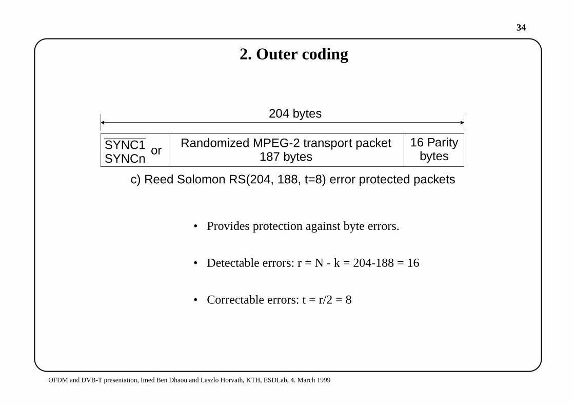
2. Outer coding
• Provides protection against byte errors.
• Detectable errors: r = N - k = 204-188 = 16
• Correctable errors: t = r/2 = 8
204 bytes
Randomized MPEG-2 transport packetSYNC1SYNCn 187 bytes
c) Reed Solomon RS(204, 188, t=8) error protected packets
16 Paritybytesor
35
OFDM and DVB-T presentation, Imed Ben Dhaou and Laszlo Horvath, KTH, ESDLab, 4. March 1999
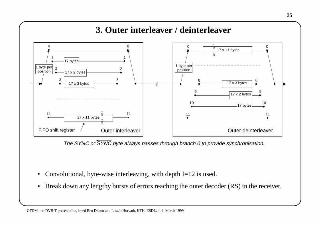
3. Outer interleaver / deinterleaver
• Convolutional, byte-wise interleaving, with depth I=12 is used.
• Break down any lengthy bursts of errors reaching the outer decoder (RS) in the receiver.
17 bytes
17 x 2 bytes
17 x 3 bytes
17 x 11 bytes
17 bytes
17 x 2 bytes
17 x 3 bytes
17 x 11 bytes
Outer interleaver Outer deinterleaver
11
3
2
1
0 0
1
2
3
11
0 0
11 11
10 10
9 9
8 8
FIFO shift register
The SYNC or SYNC byte always passes through branch 0 to provide synchronisation.
1 byte perposition
1 byte perposition
36
OFDM and DVB-T presentation, Imed Ben Dhaou and Laszlo Horvath, KTH, ESDLab, 4. March 1999
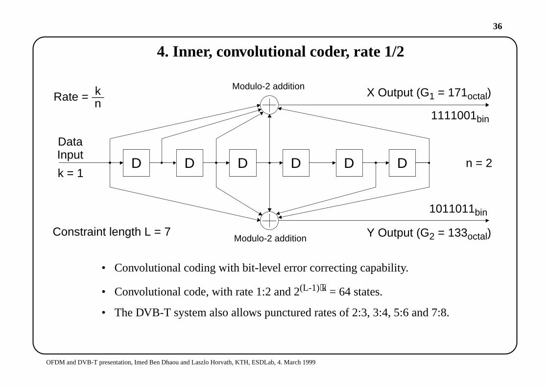
4. Inner, convolutional coder, rate 1/2
• Convolutional coding with bit-level error correcting capability.
• Convolutional code, with rate 1:2 and 2(L-1)⋅k = 64 states.
• The DVB-T system also allows punctured rates of 2:3, 3:4, 5:6 and 7:8.
D DDDD D
Modulo-2 addition
Modulo-2 addition
X Output (G1 = 171octal)
Y Output (G2 = 133octal)
1011011bin
1111001bin
DataInput
k = 1n = 2
Rate = kn
Constraint length L = 7
37
OFDM and DVB-T presentation, Imed Ben Dhaou and Laszlo Horvath, KTH, ESDLab, 4. March 1999
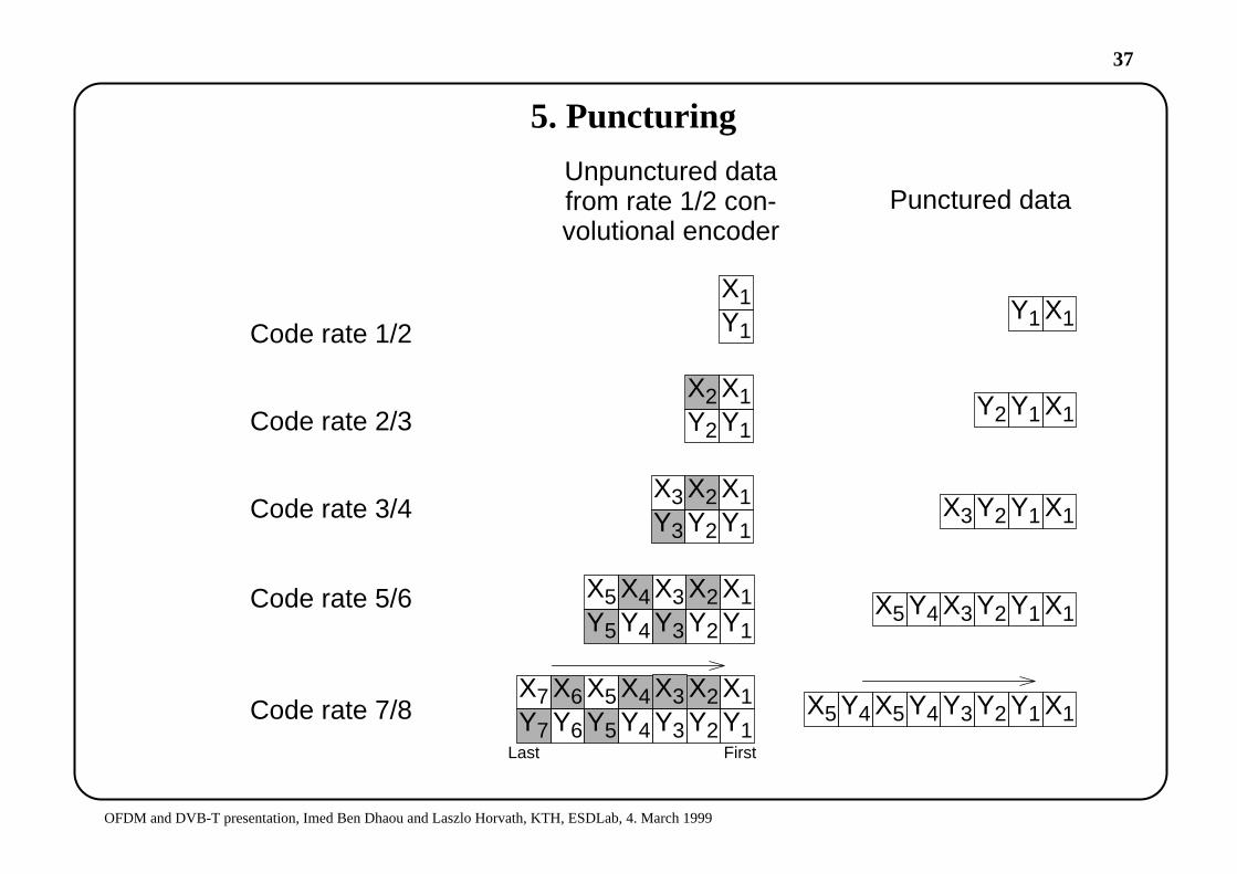
5. Puncturing
X2X4Y1Y2
X1
Punctured data
Y3Y4Y5
X5
Unpunctured datafrom rate 1/2 con-volutional encoder
Y1Y2Y3 X1X5 Y4Code rate 7/8
FirstLast
Y1Y2
X1X2Y3Y4
X3X4Y5
X5 Y1Y2X3 X1X5 Y4Code rate 5/6
Y6
X6Y7
X7 X3 X5 Y4
Code rate 3/4
Code rate 2/3
Code rate 1/2
Y1Y2
X1X2Y3
X3
Y1Y2
X1X2
Y1
X1
Y1Y2X3 X1
Y1Y2 X1
Y1 X1
38
OFDM and DVB-T presentation, Imed Ben Dhaou and Laszlo Horvath, KTH, ESDLab, 4. March 1999
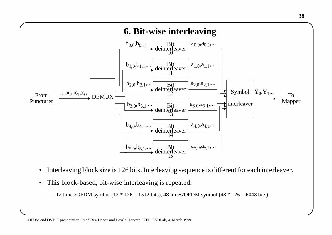
6. Bit-wise interleaving
• Interleaving block size is 126 bits. Interleaving sequence is different for each interleaver.
• This block-based, bit-wise interleaving is repeated:
– 12 times/OFDM symbol (12 * 126 = 1512 bits), 48 times/OFDM symbol (48 * 126 = 6048 bits)
Symbol
Bitdeinterleaver
I0
Bitdeinterleaver
I1
Y0,Y1,..
a1,0,a1,1,...
...,x2,x1,x0
interleaverBitdeinterleaver
I3
Bitdeinterleaver
I2
a4,0,a4,1,...
a3,0,a3,1,...
a2,0,a2,1,...
b1,0,b1,1,...
b4,0,b4,1,...
b3,0,b3,1,...
b2,0,b2,1,...
Bitdeinterleaver
I4
Bitdeinterleaver
I5
a5,0,a5,1,...
a0,0,a0,1,...b0,0,b0,1,...
b5,0,b5,1,...
DEMUX ToMapper
FromPuncturer
39
OFDM and DVB-T presentation, Imed Ben Dhaou and Laszlo Horvath, KTH, ESDLab, 4. March 1999
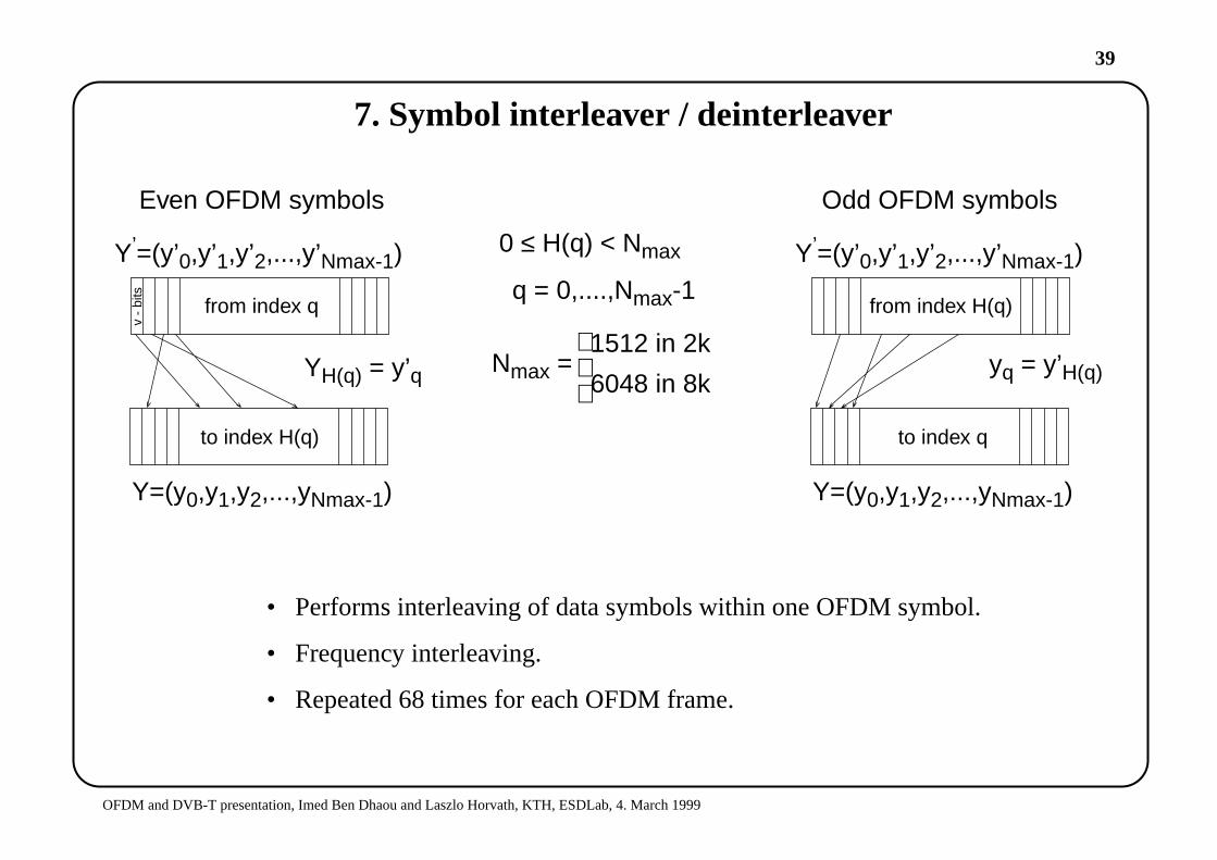
7. Symbol interleaver / deinterleaver
• Performs interleaving of data symbols within one OFDM symbol.
• Frequency interleaving.
• Repeated 68 times for each OFDM frame.
Y’=(y’0,y’1,y’2,...,y’Nmax-1)
Y=(y0,y1,y2,...,yNmax-1)
YH(q) = y’q yq = y’H(q)
from index q
to index H(q)
Y’=(y’0,y’1,y’2,...,y’Nmax-1)
Y=(y0,y1,y2,...,yNmax-1)
from index H(q)
to index q
Odd OFDM symbolsEven OFDM symbols
q = 0,....,Nmax-1
Nmax =1512 in 2k
6048 in 8k
v -
bits
0 ≤ H(q) < Nmax
40
OFDM and DVB-T presentation, Imed Ben Dhaou and Laszlo Horvath, KTH, ESDLab, 4. March 1999
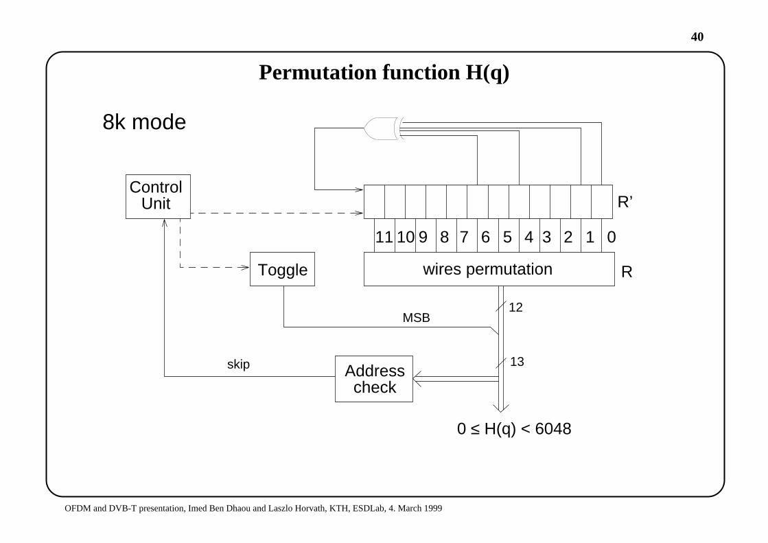
Permutation function H(q)
01234567891011
wires permutation
R’
R
Addresscheck
ControlUnit
Toggle
MSB12
13skip
0 ≤ H(q) < 6048
8k mode
41
OFDM and DVB-T presentation, Imed Ben Dhaou and Laszlo Horvath, KTH, ESDLab, 4. March 1999
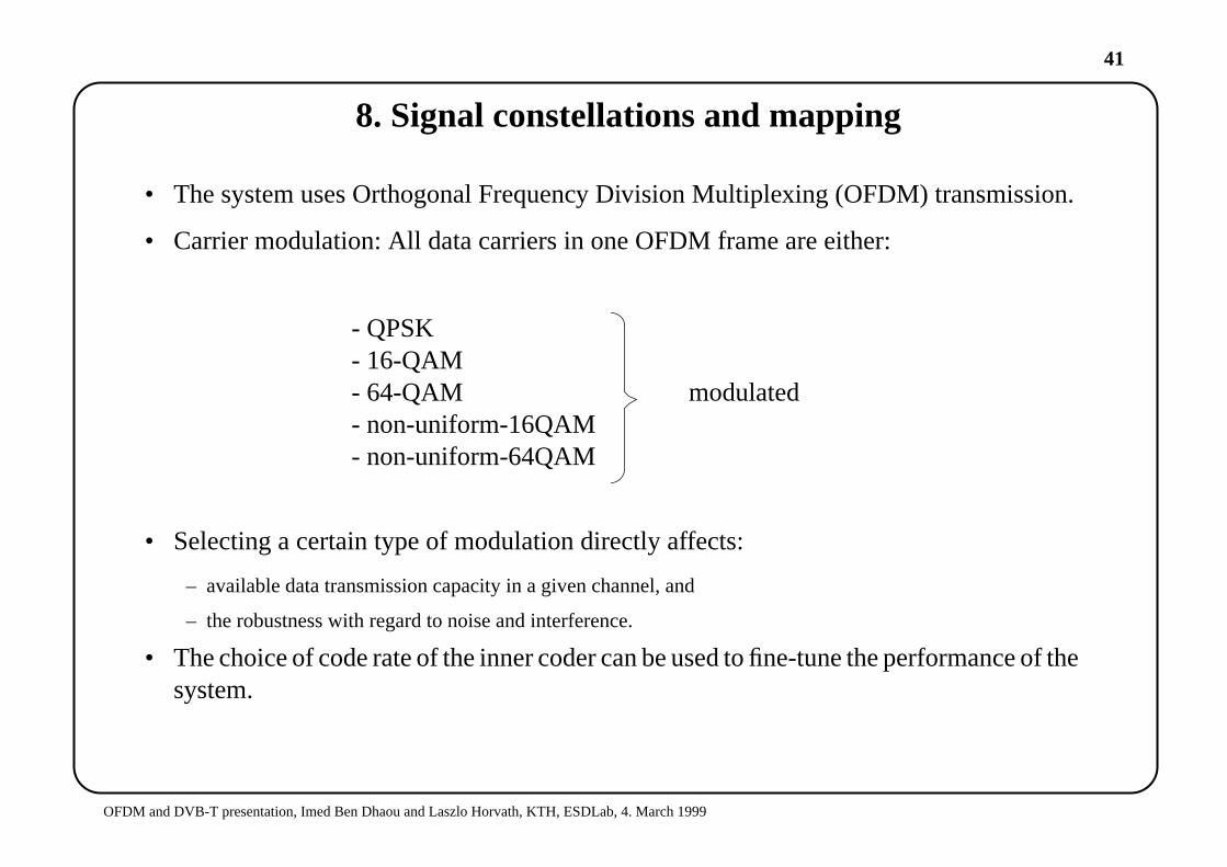
8. Signal constellations and mapping
• The system uses Orthogonal Frequency Division Multiplexing (OFDM) transmission.
• Carrier modulation: All data carriers in one OFDM frame are either:
- QPSK- 16-QAM- 64-QAM modulated- non-uniform-16QAM- non-uniform-64QAM
• Selecting a certain type of modulation directly affects:
– available data transmission capacity in a given channel, and
– the robustness with regard to noise and interference.
• The choice of code rate of the inner coder can be used to fine-tune the performance of thesystem.

42
OFDM and DVB-T presentation, Imed Ben Dhaou and Laszlo Horvath, KTH, ESDLab, 4. March 1999
OFDM frame structure
• Each OFDM-frame has a duration of TF and consist of 68 symbols.
• Each symbol has duration of TS and is constituted by:
– a set of 1705 carriers in 2k-mode.
– a set of 6817 carriers in 8k-mode.
0 1 2 67
TF
TS
1 OFDM frame
43
OFDM and DVB-T presentation, Imed Ben Dhaou and Laszlo Horvath, KTH, ESDLab, 4. March 1999
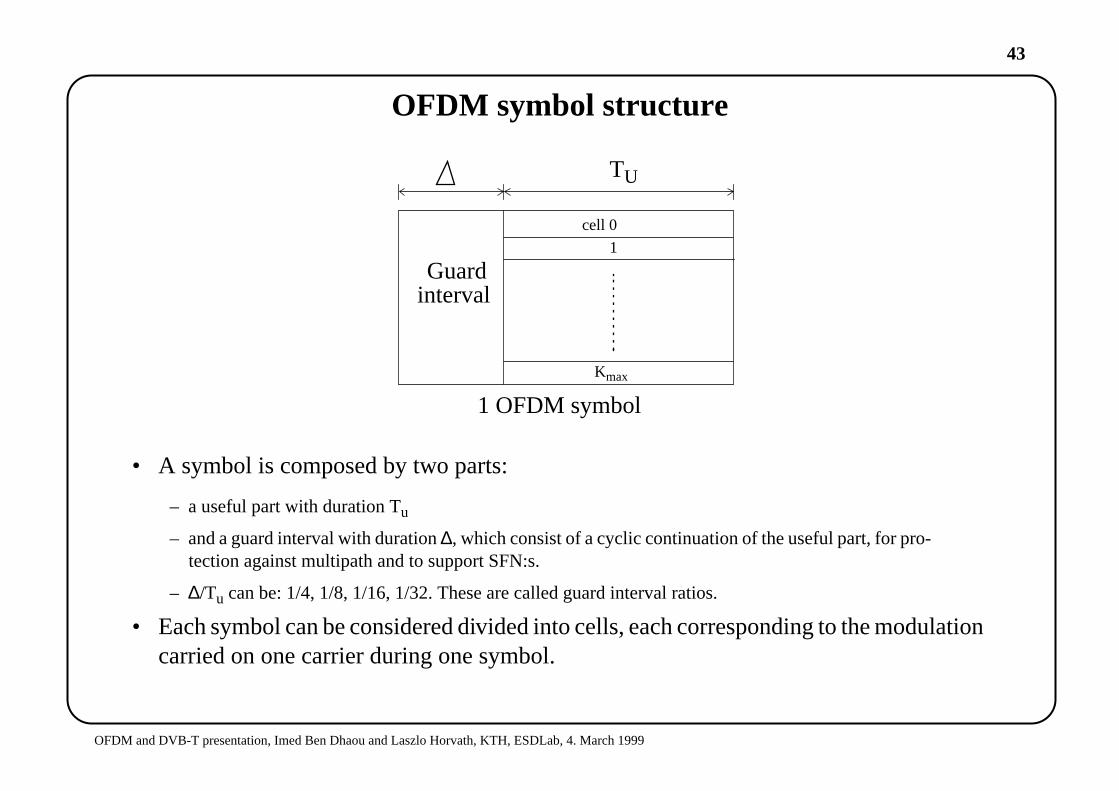
OFDM symbol structure
• A symbol is composed by two parts:
– a useful part with duration Tu
– and a guard interval with duration∆, which consist of a cyclic continuation of the useful part, for pro-tection against multipath and to support SFN:s.
– ∆/Tu can be: 1/4, 1/8, 1/16, 1/32. These are called guard interval ratios.
• Each symbol can be considered divided into cells, each corresponding to the modulationcarried on one carrier during one symbol.
Guardinterval
TU
cell 0
1
Kmax
1 OFDM symbol
44
OFDM and DVB-T presentation, Imed Ben Dhaou and Laszlo Horvath, KTH, ESDLab, 4. March 1999
OFDM frame structure
• In addition to the transmitted data the OFDM frame contains:
– Scattered pilot cells
– Continual pilot carriers
– TPS carriers (Transmission Parameter Signalling)
• The pilots are used for:
– frame synchronization
– time synchronisation
– channel estimation
– transmission mode identification
45
OFDM and DVB-T presentation, Imed Ben Dhaou and Laszlo Horvath, KTH, ESDLab, 4. March 1999
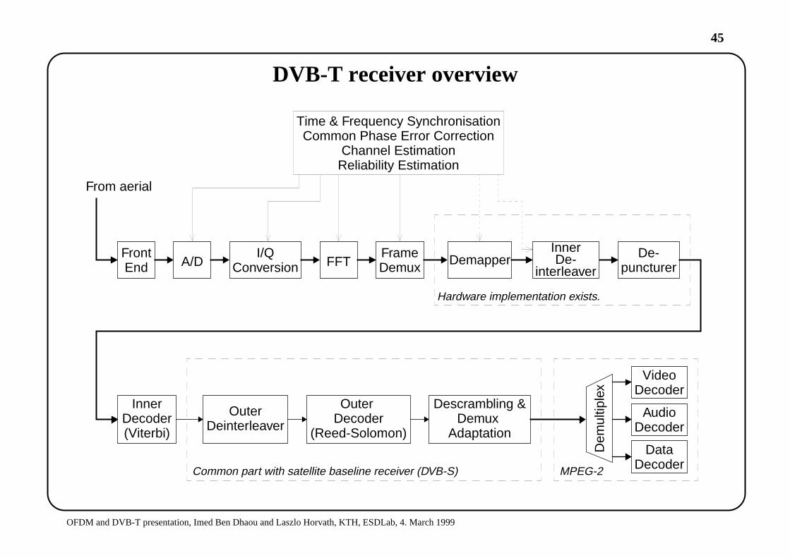
DVB-T receiver overview
DemapperA/D FFT
From aerial
Common part with satellite baseline receiver (DVB-S)
Hardware implementation exists.
FrontEnd
I/QConversion
FrameDemux
De-puncturer
InnerDe-
interleaver
Time & Frequency SynchronisationCommon Phase Error Correction
Channel EstimationReliability Estimation
InnerDecoder(Viterbi)
OuterDeinterleaver
OuterDecoder
(Reed-Solomon)
Descrambling &Demux
Adaptation
VideoDecoder
AudioDecoder
DataDecoder
Dem
ultip
lex
MPEG-2
46
OFDM and DVB-T presentation, Imed Ben Dhaou and Laszlo Horvath, KTH, ESDLab, 4. March 1999
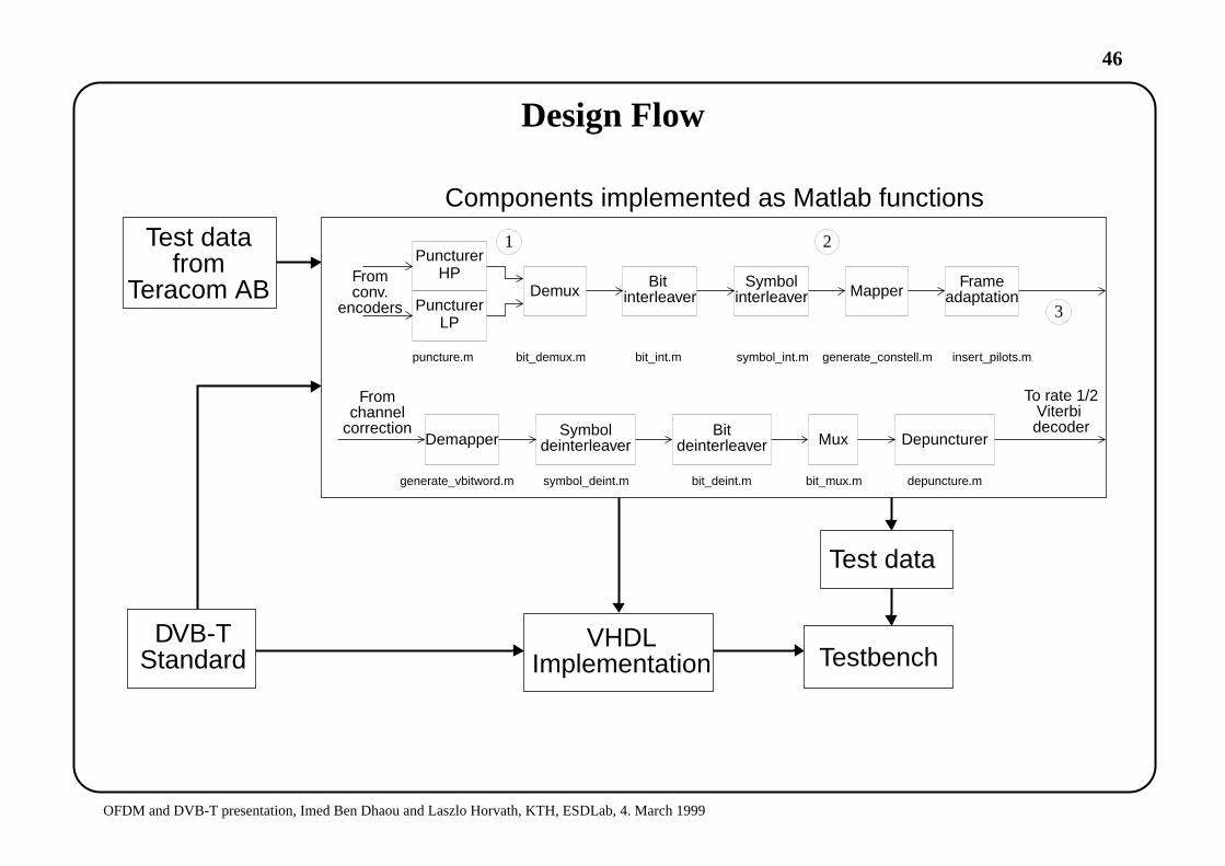
Design Flow
DVB-TStandard
PuncturerHP
PuncturerLP
DemuxBit Symbol
interleaverinterleaver Mapper
puncture.m bit_demux.m bit_int.m symbol_int.m generate_constell.m
Frameadaptation
insert_pilots.m
DemapperSymbol
deinterleaverBit
deinterleaver Mux Depuncturer
generate_vbitword.m symbol_deint.m bit_deint.m bit_mux.m depuncture.m
Fromconv.
encoders
Fromchannel
correction
To rate 1/2Viterbidecoder
1 2
3
Components implemented as Matlab functions
Test datafrom
Teracom AB
VHDLImplementation
Test data
Testbench

47
OFDM and DVB-T presentation, Imed Ben Dhaou and Laszlo Horvath, KTH, ESDLab, 4. March 1999
Initial Design
yH(q)out = yq
in
yqout = yH(q)
in
Hq q
q Hq
qqDemapper Bit
Deint.
EvenRAMout
OddRAMout
OddRAM
in
EvenRAM
in
SymbolDeint.
Data pathAddress bus
48
OFDM and DVB-T presentation, Imed Ben Dhaou and Laszlo Horvath, KTH, ESDLab, 4. March 1999
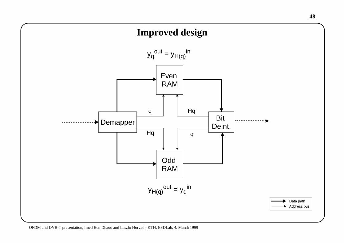
Improved design
Data pathAddress bus
yH(q)out = yq
in
yqout = yH(q)
in
Demapper BitDeint.
EvenRAM
OddRAM
q
Hq
Hq
q
49
OFDM and DVB-T presentation, Imed Ben Dhaou and Laszlo Horvath, KTH, ESDLab, 4. March 1999
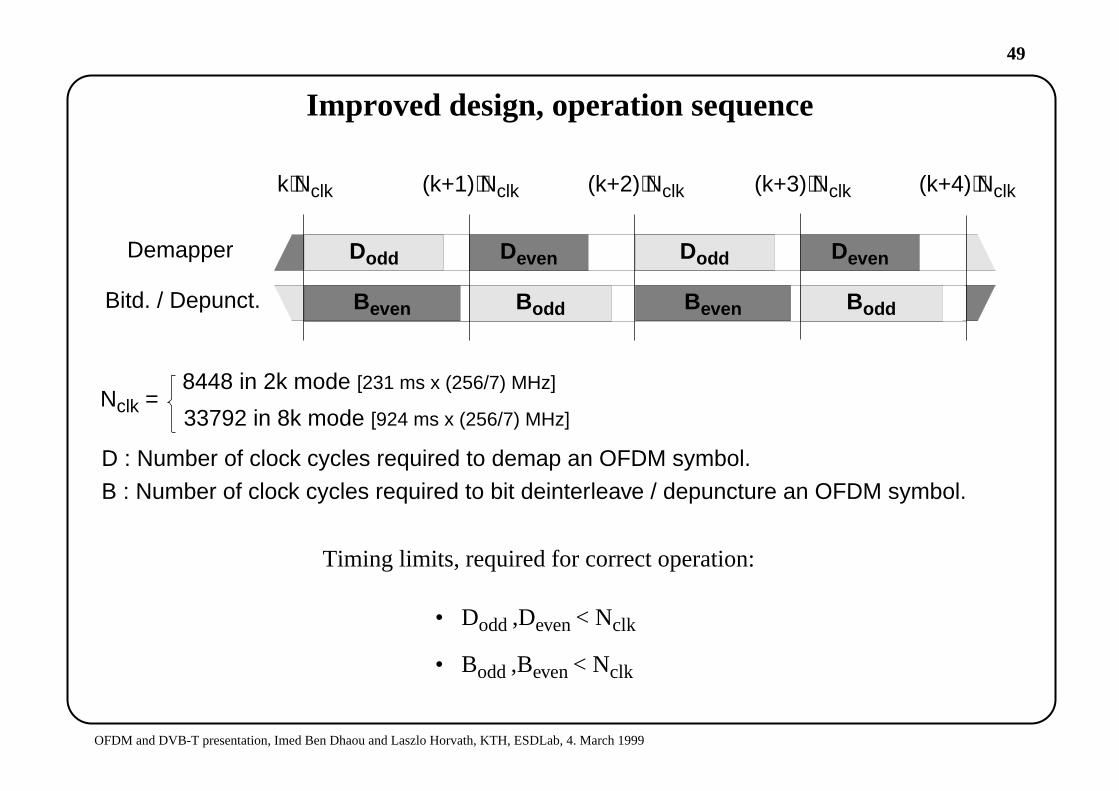
Improved design, operation sequence
Timing limits, required for correct operation:
• Dodd,Deven< Nclk
• Bodd,Beven< Nclk
Dodd
Bodd
DoddDevenDemapper
Bitd. / Depunct. Bodd
Deven
Beven
k⋅Nclk (k+1)⋅Nclk (k+2)⋅Nclk (k+3)⋅Nclk (k+4)⋅Nclk
Beven
D : Number of clock cycles required to demap an OFDM symbol.
B : Number of clock cycles required to bit deinterleave / depuncture an OFDM symbol.
Nclk =8448 in 2k mode [231 ms x (256/7) MHz]
33792 in 8k mode [924 ms x (256/7) MHz]

50
OFDM and DVB-T presentation, Imed Ben Dhaou and Laszlo Horvath, KTH, ESDLab, 4. March 1999
MUSCOD Algorithm
4 6 8 10
4
6
8
10
Re{z}
Im{z}
y2 = ‘0’y2 =’1’
4 6 8 10
4
6
8
10
Re{z}
Im{z}
y3 =’0’
y3 =’1’
‘decision lines’
• ‘decision lines’ for y2 and y3 in non-uniform-64-QAM, with α=4
4 6 8 10
4
6
8
10
Re{z}
Im{z}
y5=‘0’ y 5 =’1’
4 6 8 10
4
6
8
10
Re{z}
Im{z}
y4 =’0’
y4 =’1’
‘decision lines’
y4 =’0’
y5 = ‘0’
• ‘decision lines’ for y4 and y5 in non-uniform-64-QAM, with α=4
• The imaginary- and real axes are the ‘decision lines’ for y0 and y1. (y0 = 0 if Re > 0)

51
OFDM and DVB-T presentation, Imed Ben Dhaou and Laszlo Horvath, KTH, ESDLab, 4. March 1999
Demapper
bit 5 -> y0bit 4 -> y1bit 3 -> y2bit 2 -> y3bit 1 -> y4bit 0 -> y5
bit 7 -> 0bit 6 -> 0
DemapReorIm
im_data_in<4:0>
y0y2y4
y1y3y5
binarysign bit
+
binarysign bit
+
wordv_s<2:0>alpha_plus_s<1:0>
re_data_in<4:0>
Demapper
DemapperControl
mode<1:0> alpha<1:0> v_width<1:0>
start_demap
new_symbolMem
SelectRdWrF, CeF, OeF
q_address_s<12:0>
CeF_odd
RdWrF_odd
CeF_even
RdWrF_even
address_odd<12:0>
address_even<12:0>
symbol_sign
DemapReorIm
OeF_odd
OeF_even
symbdeint
vbitword<7:0>
HqShiftReg
skip
setinitbit
Hq_address_s<12:0>
52
OFDM and DVB-T presentation, Imed Ben Dhaou and Laszlo Horvath, KTH, ESDLab, 4. March 1999
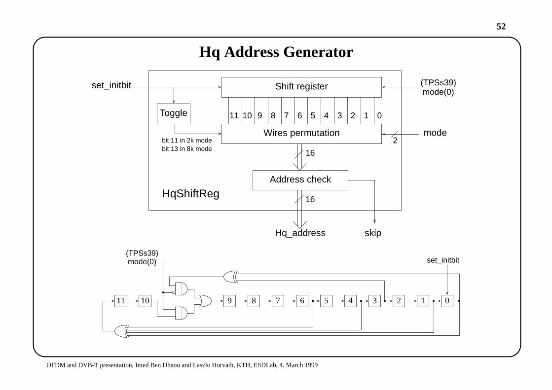
Hq Address Generator
01234567891011
Shift register
Wires permutation
Toggle
set_initbit (TPSs39)mode(0)
mode
Address check
bit 11 in 2k modebit 13 in 8k mode
16
16
Hq_address skip
HqShiftReg
2
05 4 3 2 167891011
(TPSs39)mode(0) set_initbit
53
OFDM and DVB-T presentation, Imed Ben Dhaou and Laszlo Horvath, KTH, ESDLab, 4. March 1999
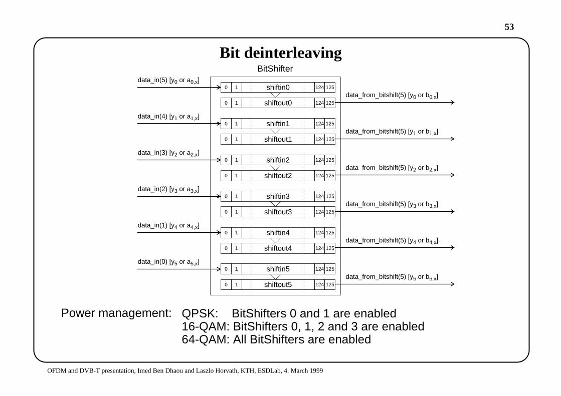
Bit deinterleaving
shiftin00 1 124 125
0 1 124 125shiftout0
shiftin10 1 124 125
0 1 124 125shiftout1
shiftin20 1 124 125
0 1 124 125shiftout2
shiftin30 1 124 125
0 1 124 125shiftout3
shiftin40 1 124 125
0 1 124 125shiftout4
shiftin50 1 124 125
0 1 124 125shiftout5
data_in(5) [y0 or a0,x]
data_in(4) [y1 or a1,x]
data_in(3) [y2 or a2,x]
data_in(2) [y3 or a3,x]
data_in(1) [y4 or a4,x]
data_in(0) [y5 or a5,x]
data_from_bitshift(5) [y0 or b0,x]
data_from_bitshift(5) [y1 or b1,x]
data_from_bitshift(5) [y2 or b2,x]
data_from_bitshift(5) [y3 or b3,x]
data_from_bitshift(5) [y4 or b4,x]
data_from_bitshift(5) [y5 or b5,x]
BitShifter
Power management: QPSK: BitShifters 0 and 1 are enabled16-QAM: BitShifters 0, 1, 2 and 3 are enabled64-QAM: All BitShifters are enabled
54
OFDM and DVB-T presentation, Imed Ben Dhaou and Laszlo Horvath, KTH, ESDLab, 4. March 1999
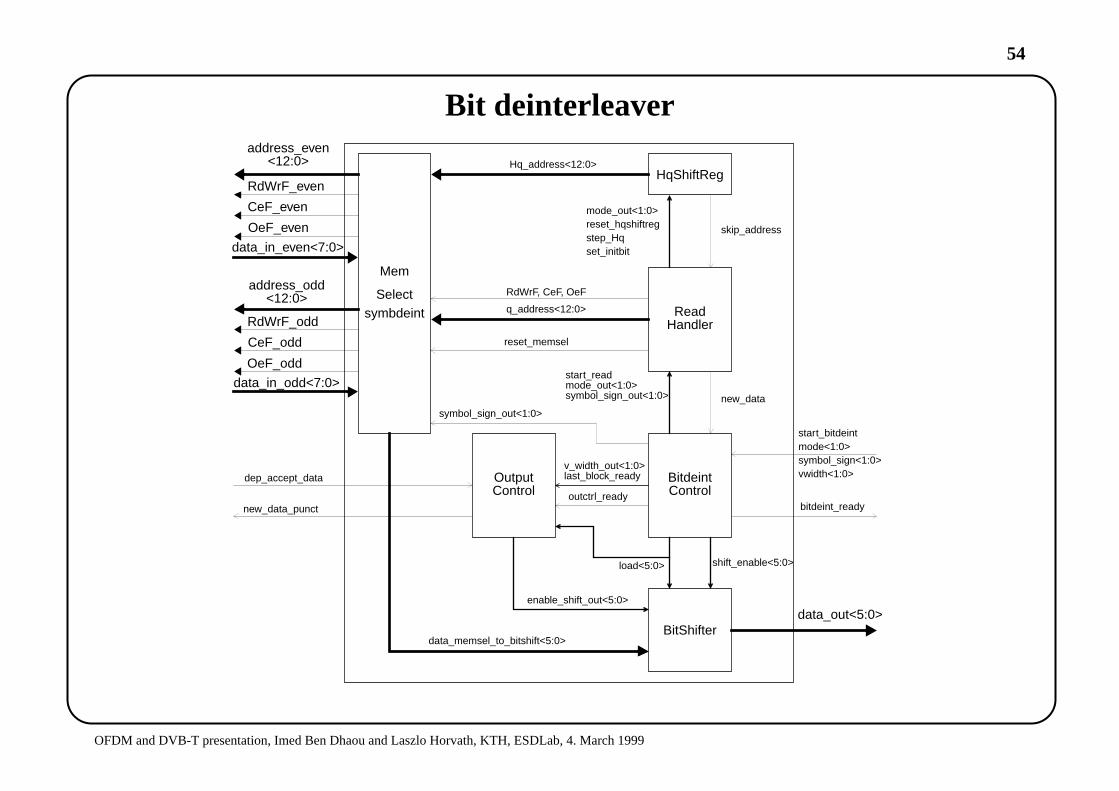
Bit deinterleaver
Mem
Select
CeF_odd
RdWrF_odd
CeF_even
RdWrF_even
address_odd<12:0>
address_even<12:0>
OeF_odd
OeF_even
symbdeint
HqShiftReg
data_in_odd<7:0>
data_in_even<7:0>
ReadHandler
RdWrF, CeF, OeF
q_address<12:0>
reset_memsel
Hq_address<12:0>
mode_out<1:0>reset_hqshiftregstep_Hqset_initbit
skip_address
BitdeintControl
BitShifter
start_readmode_out<1:0>symbol_sign_out<1:0> new_data
OutputControl
v_width_out<1:0>last_block_ready
outctrl_ready
shift_enable<5:0>load<5:0>
enable_shift_out<5:0>
data_out<5:0>
data_memsel_to_bitshift<5:0>
bitdeint_ready
start_bitdeintmode<1:0>symbol_sign<1:0>vwidth<1:0>
symbol_sign_out<1:0>
dep_accept_data
new_data_punct

55
OFDM and DVB-T presentation, Imed Ben Dhaou and Laszlo Horvath, KTH, ESDLab, 4. March 1999
Puncturing / Depuncturing
I10I20
A0B0
I30I31I40I41I42
B1B1
A2A2
A2
I10
I20 I31
I42
B0 B1
A2A0
MUX 1 :MUX 0 :
Depunctured data
Unpunctureddata from conv.
encoder
Depuncture pattern for:
First Last
16-QAM (v = 4), non-hierarchical transmission with code rate 3/4.
Depuncture
First Last
64-QAM (v = 6) hierarchical transmission, low priority stream with code rate 3/4.
pattern
A2B0 B1 B2
A0 A1
B0 B1 A2A0Punctured data
a.
b.
d.
e.
c. Delayed data
56
OFDM and DVB-T presentation, Imed Ben Dhaou and Laszlo Horvath, KTH, ESDLab, 4. March 1999
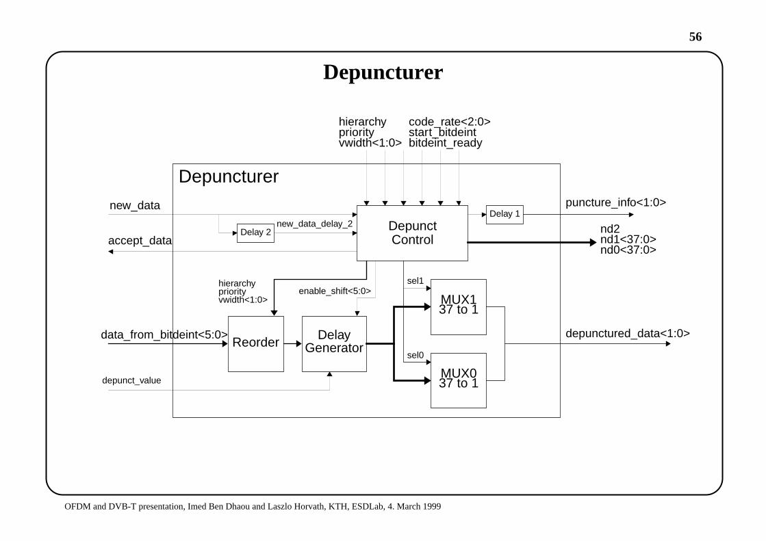
Depuncturer
Reorder Delay
MUX137 to 1
DepunctControl
MUX037 to 1
Depuncturer
depunctured_data<1:0>
puncture_info<1:0>
data_from_bitdeint<5:0>
sel0
sel1
Generator
Delay 2
new_dataDelay 1
new_data_delay_2
enable_shift<5:0>
depunct_value
hierarchypriority
code_rate<2:0>
vwidth<1:0>
accept_datand2nd1<37:0>nd0<37:0>
start_bitdeintbitdeint_ready
hierarchypriorityvwidth<1:0>
57
OF
DM
and
DV
B-T
pre
sent
atio
n, Im
ed B
en D
haou
and
Las
zlo
Hor
vath
, KT
H, E
SD
Lab,
4. M
arch
199
9
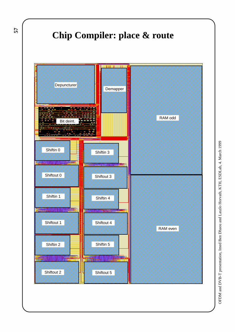
RAM odd
RAM even
DepuncturerDemapper
Shiftin 0
Shiftin 1
Shiftin 2
Shiftin 4
Shiftin 3
Shiftin 5
Shiftout 1
Shiftout 3Shiftout 0
Shiftout 4
Shiftout 2 Shiftout 5
Bit deint.
Chip Compiler: place & route

58
OF
DM
and
DV
B-T
pre
sent
atio
n, Im
ed B
en D
haou
and
Las
zlo
Hor
vath
, KT
H, E
SD
Lab,
4. M
arch
199
9
a. Part of the odd RAM
b. The layout of the chip
c. Shiftout block6573 transistors
Area: 68,1 mm2Size: 7,21mm x 9,45 mm
Size: 1,88 mm x 0,95 mmArea: 1,80 mm2
Compass Layout2
59
OFDM and DVB-T presentation, Imed Ben Dhaou and Laszlo Horvath, KTH, ESDLab, 4. March 1999
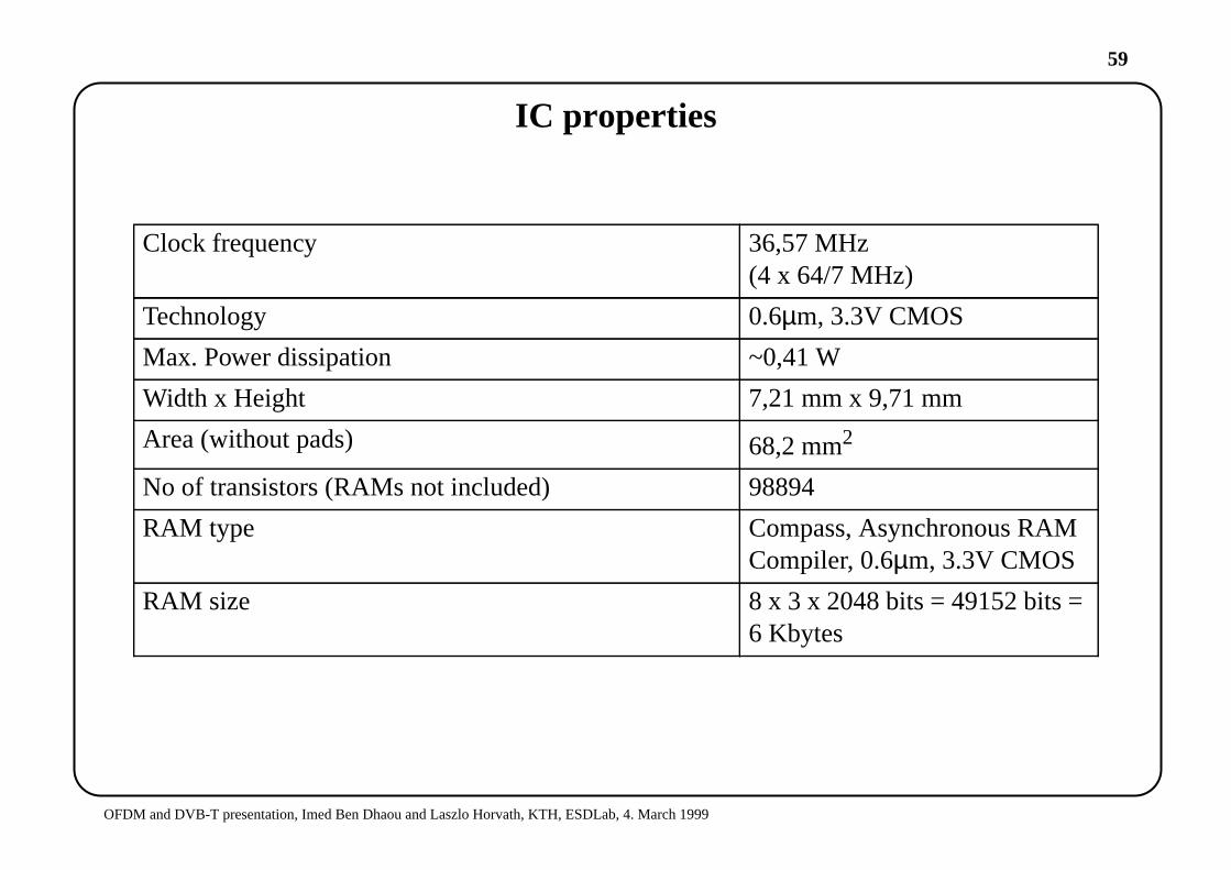
IC properties
Clock frequency 36,57 MHz(4 x 64/7 MHz)
Technology 0.6µm, 3.3V CMOS
Max. Power dissipation ~0,41 W
Width x Height 7,21 mm x 9,71 mm
Area (without pads) 68,2 mm2
No of transistors (RAMs not included) 98894
RAM type Compass, Asynchronous RAMCompiler, 0.6µm, 3.3V CMOS
RAM size 8 x 3 x2048 bits = 49152 bits =6 Kbytes
60
OFDM and DVB-T presentation, Imed Ben Dhaou and Laszlo Horvath, KTH, ESDLab, 4. March 1999
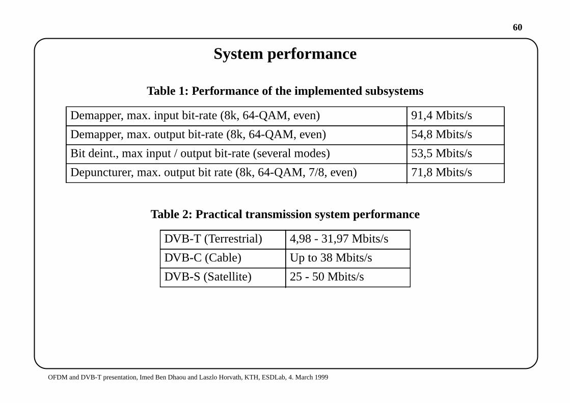
System performance
Table 1: Performance of the implemented subsystems
Table 2: Practical transmission system performance
Demapper, max. input bit-rate (8k, 64-QAM, even) 91,4 Mbits/s
Demapper, max. output bit-rate (8k, 64-QAM, even) 54,8 Mbits/s
Bit deint., max input / output bit-rate (several modes) 53,5 Mbits/s
Depuncturer, max. output bit rate (8k, 64-QAM, 7/8, even) 71,8 Mbits/s
DVB-T (Terrestrial) 4,98 - 31,97 Mbits/s
DVB-C (Cable) Up to 38 Mbits/s
DVB-S (Satellite) 25 - 50 Mbits/s
61
OFDM and DVB-T presentation, Imed Ben Dhaou and Laszlo Horvath, KTH, ESDLab, 4. March 1999
Conclusions and future work
• DVB-T uses a very effective digital communication method for transmitting MPEG2video/audio streams.
• DVB-T got a wide acceptance in Europe, with potential expansion to support futuremobile communications and data exchange.
• DVB-T receiver is cost effective, with low-power implementation possiblities.
• A high-data rate, low power implementation of the demapper, inner deinterleaver anddepuncturer, used in the OFDM chain, was proposed and implemented.
• Future work will concentrate on finding an ultra-low power implementation for the bitdeinterleaver.


