
http://www.iaeme.com/IJARET/index.asp 9 [email protected]
International Journal of Advanced Research in Engineering and Technology
(IJARET) Volume 7, Issue 2, March-April 2016, pp. 09-20, Article ID: IJARET_07_02_002
Available online at
http://www.iaeme.com/IJARET/issues.asp?JType=IJARET&VType=7&IType=2
Journal Impact Factor (2016): 8.8297 (Calculated by GISI) www.jifactor.com
ISSN Print: 0976-6480 and ISSN Online: 0976-6499
© IAEME Publication
___________________________________________________________________________
PERFORMANCE OPTIMIZATION OF
HYBRID SOLAR HEATING SYSTEM USING
THERMOELECTRIC GENERATOR
Sabah M. Hadi, Aed Ibrahim Owaid and Rasim Abbas Ahmmed
Solar Researches Centre, Renewable Energies Directorate,
Ministry of Science and Technology, Republic of Iraq
ABSTRACT
The hybrid solar system assumed to be consist of thermoelectric generator
(TEG) and evacuated tube with efficiency extracted under standard condition
of 1000 w/m2and ambient temperature 25 C, then the efficiency of hybrid
system measured at different solar radiation and temperature. In addition the
thermal efficiency and electrical efficiency are extracted. The study was done
with different figure of merit (ZT) (0.5, 1, 1.5, 2, 2.5, 3, 3.5, 4) of
thermoelectric generator (TEG). The heat transfer coefficient of evacuated
tube 0.89 W/k.m and temperature dependent that transfer coefficient
0.001w/k2. m the calculation and graphs were done by MATLAB program.
Key words: Solar, Evacuated Tube, TEG, Efficiency, MATLAB
Cite this Article: Sabah M. Hadi, Aed Ibrahim Owaid and Rasim Abbas
Ahmmed, Performance Optimization of Hybrid Solar Heating System Using
Thermoelectric Generator. International Journal of Advanced Research in
Engineering and Technology, 7(2), 2016, pp. 09-20.
http://www.iaeme.com/IJARET/issues.asp?JType=IJARET&VType=7&IType=2
1. INTRODUCTION
The greatest advantage of solar energy as compared with other forms of energy is that
it is clean and can be supplied without any environmental pollution. Over the past
century fossil fuels have provided most of our energy because these are much cheaper
and more convenient than energy from alternative energy sources, and until recently
environmental pollution has been of little concern [1].
The solar energy is available in abundance and has potential to meet the current
heating and electricity needs. However in most cases the solar systems are limited to
providing either heat or electricity. Recently, hybrid systems are developed, either
with photovoltaic or thermoelectric to generate both electrical power and thermal
energy or heat [2]. Thermoelectric power generation is one of the current interests in
clean energy research in view of direct solar power generation. Thermoelectric power
Sabah M. Hadi, Aed Ibrahim Owaid and Rasim Abbas Ahmmed
http://www.iaeme.com/IJARET/index.asp 10 [email protected]
generation be-comes an attractive application. Recent research analyses were
proposed in the open literature to cover the various aspects of energy
generation[3]Thermoelectric have large potential to become an alternative power
source for electrical power supply, as they could provide co-generation system
anywhere thermal gradients exist. The most efficient way for improving the
performance of thermoelectric power generation systems is to use it with hybrid
systems. Thermoelectric module can be used with flat plate collectors, parabolic
collectors and parabolic dish or evacuated tube collectors to generate heat and
electricity simultaneously. Such hybrid system improves the overall performance of
the thermoelectric power generation system which can be made cost effective [2].
This hybrid system takes several form using for example Fresnel lens which is
concentrate the solar rays on the thermoelectric generator and produce the electrical
power with electrical conversion efficiency of 15%from the incident solar energy.
The hybrid system depend on three subsystem solar absorption system,
thermoelectric system and electrical energy management [4, 5] also dish concentrator
can be used within the hybrid system as the energy conversion and also it is highly
suitable for isolated energy demand where the conventional grid is not feasible or
available [6].
2. THEORETICAL PART
2.1. The Hybrid System
The conversion process of the solar energy indirectly can be done by several ways and
by several kinds of the thermal units. Which depend on dish concentrator and the
other on dish concentrator and so on.
The thermal units convert the solar energy to thermal energy become electrical
energy by mechanical way, so in order to prevent the mechanical way which needs
special maintenances and another requirements, the researchers followed the way
(STEG) which still in the process of research and training.
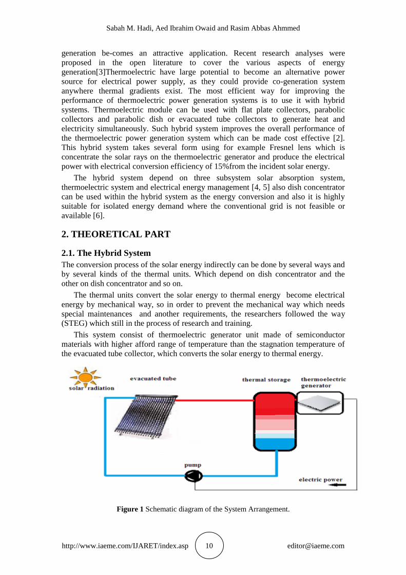
This system consist of thermoelectric generator unit made of semiconductor
materials with higher afford range of temperature than the stagnation temperature of
the evacuated tube collector, which converts the solar energy to thermal energy.
Figure 1 Schematic diagram of the System Arrangement.

Performance Optimization of Hybrid Solar Heating System Using Thermoelectric Generator
http://www.iaeme.com/IJARET/index.asp 11 [email protected]
2.1.1. Thermoelectric Generator (TEG)
The global energy crisis has motivated researchers to explore alternative means of
generating power. One approach to providing electrical energy is by direct conversion
of heat to electricity using thermoelectric generators (TEGs). It is attractive to use
TEGs because they have no mechanical parts, resulting in a power system that is
silent, reliable, environment-friendly, and virtually unlimited lifetime [7].
The basic theory behind this TEG is "seebeck effect". Seebeck effect was
discovered by Thomas Seebeck in 1821. When a temperature difference is recognized
between the hot and cold junctions of two dissimilar materials (metals or
semiconductors) a voltage is generated, this voltage is called Seebeck voltage. Indeed
this phenomenon is applied to thermocouples that are extensively used for
temperature measurements. When a Thermoelectric material (Thermoelectric Module
or Thermocouple) held in-between temperature gradient it generate some voltage. In
fact, this phenomenon is applied to thermocouples that are extensively used for
temperature measurements. Base on this Seebeck effect, thermoelectric devices can
act as electrical power generators [8] .as shown in fig. (2)[9]
Figure 2 Illustration of Seebeck effect
Seebeck coefficient can be found by the equation (1) where ΔT, ΔV are
temperature difference and potential difference respectively through the two junction
between the two equations (2):
α
α
As mentioned above the thermoelectric generator consist of two different
materials, So the conversion efficiency of thermal energy depends on the physical
properties of thermal conductivity and electrical conductivity for this materials, so
find efficiency was associated with finding (Z)figure of merit which can be defined
as it is one of the most important concepts of thermoelectric that is ability of heat
conversion to electricity[10], So the finding of (Z) figure of Merit for any material
concerning the thermoelectric generator must be found by the equation (3) so
that()represent the electrical conductivity and can be measured by ampere. volt-1
.
meter-1
and (λ) is thermal conductivity for the material and can be measured by
watt.meter-1
.kelvin-1
Sabah M. Hadi, Aed Ibrahim Owaid and Rasim Abbas Ahmmed
http://www.iaeme.com/IJARET/index.asp 12 [email protected]
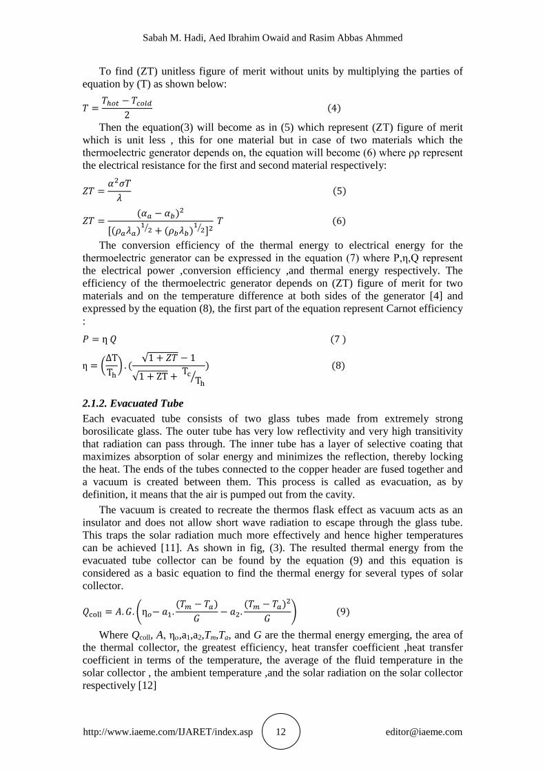
To find (ZT) unitless figure of merit without units by multiplying the parties of
equation by (T) as shown below:
Then the equation(3) will become as in (5) which represent (ZT) figure of merit
which is unit less , this for one material but in case of two materials which the
thermoelectric generator depends on, the equation will become (6) where ρρ represent
the electrical resistance for the first and second material respectively:
The conversion efficiency of the thermal energy to electrical energy for the
thermoelectric generator can be expressed in the equation (7) where P,η,Q represent
the electrical power ,conversion efficiency ,and thermal energy respectively. The
efficiency of the thermoelectric generator depends on (ZT) figure of merit for two
materials and on the temperature difference at both sides of the generator [4] and
expressed by the equation (8), the first part of the equation represent Carnot efficiency
:
ƞ
2.1.2. Evacuated Tube
Each evacuated tube consists of two glass tubes made from extremely strong
borosilicate glass. The outer tube has very low reflectivity and very high transitivity
that radiation can pass through. The inner tube has a layer of selective coating that
maximizes absorption of solar energy and minimizes the reflection, thereby locking
the heat. The ends of the tubes connected to the copper header are fused together and
a vacuum is created between them. This process is called as evacuation, as by
definition, it means that the air is pumped out from the cavity.
The vacuum is created to recreate the thermos flask effect as vacuum acts as an
insulator and does not allow short wave radiation to escape through the glass tube.
This traps the solar radiation much more effectively and hence higher temperatures
can be achieved [11]. As shown in fig, (3). The resulted thermal energy from the
evacuated tube collector can be found by the equation (9) and this equation is
considered as a basic equation to find the thermal energy for several types of solar
collector.
Where Qcoll, A, η,a1,a2,Tm,Ta, and G are the thermal energy emerging, the area of
the thermal collector, the greatest efficiency, heat transfer coefficient ,heat transfer
coefficient in terms of the temperature, the average of the fluid temperature in the
solar collector , the ambient temperature ,and the solar radiation on the solar collector
respectively [12]

Performance Optimization of Hybrid Solar Heating System Using Thermoelectric Generator
http://www.iaeme.com/IJARET/index.asp 13 [email protected]
Figure 3 Photographic picture for evacuated tube.
3. THE CALCULATION
3.1. Calculation of amount of change energy obtained with the difference
in the temperature of the heat transfer fluid within the evacuated tube
In order to calculate the amount of change in the produced energy by the solar thermal
collector for the total area of 1 m2 and with solar radiation of 1000 w/m
2, ambient
temperature (25C), heat transfer coefficient (0.0089 w/m2k), and heat transfer
coefficient in term of temperature (0.001 w/m2k), and using equation (9) with helping
of the MATLAB program, the results would be shown in figure (4):
Figure 4 The Graph shown the change amount of the resulted energy from the evacuated tube
collector of area (1m2) with the change of temperature average of heat transfer fluid.
0 50 100 150 200 250 300250
300
350
400
450
500
550
600
Difference of mean collector fluid and ambient temperature C
Colle
cto
r outp
ut
[w/m
2]
G=1000 w/m2
y = - 0.001*x2 - 0.89*x + 5.9e+002
Sabah M. Hadi, Aed Ibrahim Owaid and Rasim Abbas Ahmmed
http://www.iaeme.com/IJARET/index.asp 14 [email protected]
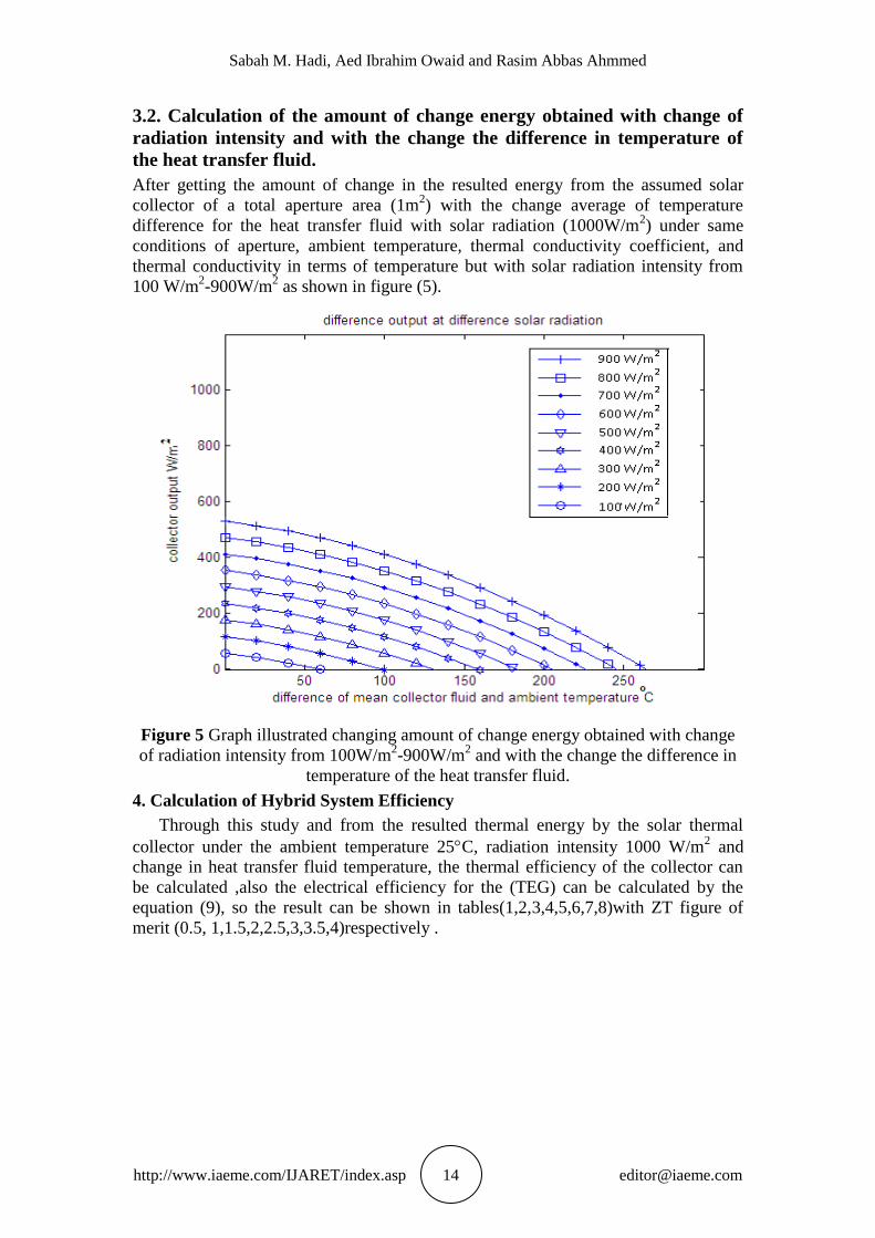
3.2. Calculation of the amount of change energy obtained with change of
radiation intensity and with the change the difference in temperature of
the heat transfer fluid.
After getting the amount of change in the resulted energy from the assumed solar
collector of a total aperture area (1m2) with the change average of temperature
difference for the heat transfer fluid with solar radiation (1000W/m2) under same
conditions of aperture, ambient temperature, thermal conductivity coefficient, and
thermal conductivity in terms of temperature but with solar radiation intensity from
100 W/m2-900W/m
2 as shown in figure (5).
Figure 5 Graph illustrated changing amount of change energy obtained with change
of radiation intensity from 100W/m2-900W/m
2 and with the change the difference in
temperature of the heat transfer fluid.
4. Calculation of Hybrid System Efficiency
Through this study and from the resulted thermal energy by the solar thermal
collector under the ambient temperature 25C, radiation intensity 1000 W/m2 and
change in heat transfer fluid temperature, the thermal efficiency of the collector can
be calculated ,also the electrical efficiency for the (TEG) can be calculated by the
equation (9), so the result can be shown in tables(1,2,3,4,5,6,7,8)with ZT figure of
merit (0.5, 1,1.5,2,2.5,3,3.5,4)respectively .

Performance Optimization of Hybrid Solar Heating System Using Thermoelectric Generator
http://www.iaeme.com/IJARET/index.asp 15 [email protected]
Table 1 Show the result of the electrical and thermal energy when the intensity is 1000W/m2,
temperature 25ᵒC and figure of merit 0.5
Table 2 Show the result of the electrical and thermal energy when the intensity is 1000W/m2,
temperature25C, and figure of merit1.0
Total
efficiency
Total output
energy
Electrical
Efficiency
Thermal
efficiency
Thermal
Energy
Medium
Temp.
Temp.
Difference
0.590 590 0 0.590 590 52 0
0.586 586.7316 0400.0 0.567 265 20 52
0.562 562.2765 040022 0.543 2.0 52 20
0.533 533.6991 040050 0.517 517 000 52
0.505 505.1899 040500 0.491 .00 052 000
0.474 474.9917 040520 0.463 463 020 052
0.444 444.1556 04050. 0.434 .0. 052 020
0.411 411.5839 040500 0.403 403 500 052
0.379 379.2540 040002 0.372 055 552 500
0.345 345.1020 040000 0.339 339 520 552
0.310 310.0935 040065 0.305 002 552 520
0.273 273.1964 040026 0.269 269 000 552
Total
efficiency
Total output
energy
Electrical
Efficiency
Thermal
efficiency
Thermal
Energy
Medium
Temp.
Temp.
Difference
0.590 590 0 0.590 590 52 0
0.601 601.587 0.061 0.567 265 20 52
0.577 577.209 0.063 0.543 2.0 52 20
0.546 546.469 0.057 0.517 517 000 52
0.517 516.532 0.052 0.491 .00 052 000
0.485 484.761 0.047 0.463 463 020 052
0.452 452.228 0.042 0.434 .0. 052 020
0.419 418.717 0.039 0.403 403 500 052
0.385 385.020 0.035 0.372 055 552 500
0.350 350.187 0.033 0.339 339 520 552
0.314 314.150 0.030 0.305 002 552 520
0.277 276.532 0.028 0.269 269 000 552

Sabah M. Hadi, Aed Ibrahim Owaid and Rasim Abbas Ahmmed
http://www.iaeme.com/IJARET/index.asp 16 [email protected]
Table 3 Show the result of the electrical and thermal energy when the intensity is 1000W/m2,
temperature25C, and figure of merit 1.5
Total
efficiency
Total output
energy
Electrical
Efficiency
Thermal
efficiency
Thermal
Energy
Medium
Temp.
Temp.
Difference
0.590 590 0 0.590 590 52 0
0.612 612.927 0.081 0.567 265 20 52
0.589 589.155 0.085 0.543 2.0 52 20
0.557 557.326 0.078 0.517 517 000 52
0.525 525.370 0.070 0.491 .00 052 000
0.492 492.632 0.064 0.463 463 020 052
0.459 459.172 0.058 0.434 .0. 052 020
0.424 424.359 0.053 0.403 403 500 052
0.390 390.228 0.049 0.372 055 552 500
0.354 354.255 0.045 0.339 339 520 552
0.317 317.810 0.042 0.305 002 552 520
0.279 279.491 0.039 0.269 269 000 552
Table 4 Show the result of the electrical and thermal energy when the intensity is 1000W/m2,
temperature25C, and figure of merit 2.0
Total
efficiency
Total output
energy
Electrical
Efficiency
Thermal
efficiency
Thermal
Energy
Medium
Temp.
Temp.
Difference
0.590 590 0 0.590 590 52 0
0.662 622.6227 040000 0.567 265 20 52
0.598 598.9833 040000 0.543 2.0 52 20
0.566 566.5286 040020 0.517 517 000 52
0.533 533.7170 040050 0.491 .00 052 000
0.499 499.5307 040500 0.463 463 020 052
0.465 465.2046 040500 0.434 .0. 052 020
0.429 429.5174 040620 0.403 403 500 052
0.394 394.5432 040606 0.372 055 552 500
0.358 358.0518 040265 0.339 339 520 552
0.320 320.9515 040250 0.305 002 552 520
0.282 282.1541 040.00 0.269 269 000 552
Performance Optimization of Hybrid Solar Heating System Using Thermoelectric Generator
http://www.iaeme.com/IJARET/index.asp 17 [email protected]
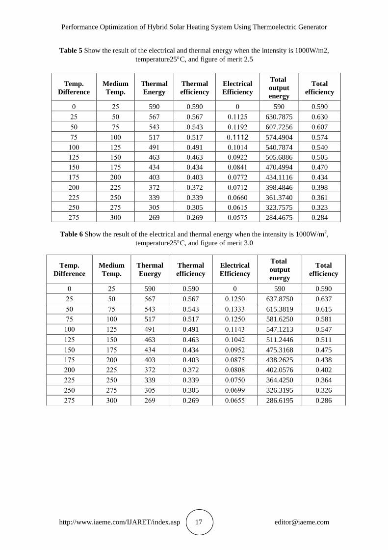
Table 5 Show the result of the electrical and thermal energy when the intensity is 1000W/m2,
temperature25C, and figure of merit 2.5
Table 6 Show the result of the electrical and thermal energy when the intensity is 1000W/m2,
temperature25C, and figure of merit 3.0
Total
efficiency
Total output
energy
Electrical
Efficiency
Thermal
efficiency
Thermal
Energy
Medium
Temp.
Temp.
Difference
0.590 590 0 0.590 590 52 0
0.630 630.7875 040052 0.567 265 20 52
0.607 607.7256 040005 0.543 2.0 52 20
0.574 574.4904 02111. 0.517 517 000 52
0.540 540.7874 04000. 0.491 .00 052 000
0.505 505.6886 040055 0.463 463 020 052
0.470 470.4994 0400.0 0.434 .0. 052 020
0.434 434.1116 040555 0.403 403 500 052
0.398 398.4846 040505 0.372 055 552 500
0.361 361.3740 040660 0.339 339 520 552
0.323 323.7575 040602 0.305 002 552 520
0.284 284.4675 040252 0.269 269 000 552
Total
efficiency
Total output
energy
Electrical
Efficiency
Thermal
efficiency
Thermal
Energy
Medium
Temp.
Temp.
Difference
0.590 590 0 0.590 590 52 0
0.637 637.8750 040520 0.567 265 20 52
0.615 615.3819 040000 0.543 2.0 52 20
0.581 581.6250 040520 0.517 517 000 52
0.547 547.1213 0400.0 0.491 .00 052 000
0.511 511.2446 0400.5 0.463 463 020 052
0.475 475.3168 040025 0.434 .0. 052 020
0.438 438.2625 040052 0.403 403 500 052
0.402 402.0576 040000 0.372 055 552 500
0.364 364.4250 040520 0.339 339 520 552
0.326 326.3195 040600 0.305 002 552 520
0.286 286.6195 040622 0.269 560 000 552
Sabah M. Hadi, Aed Ibrahim Owaid and Rasim Abbas Ahmmed
http://www.iaeme.com/IJARET/index.asp 18 [email protected]
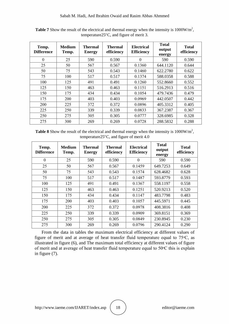
Table 7 Show the result of the electrical and thermal energy when the intensity is 1000W/m2,
temperature25C, and figure of merit 3.
Table 8 Show the result of the electrical and thermal energy when the intensity is 1000W/m2,
temperature25C, and figure of merit 4.0
Total
efficiency
Total output
energy
Electrical
Efficiency
Thermal
efficiency
Thermal
Energy
Medium
Temp.
Temp.
Difference
0.590 590 0 0.590 590 52 0
0.649 649.7253 040.20 0.567 265 20 52
0.628 628.4682 04025. 0.543 2.0 52 20
0.593 593.8779 040.05 0.517 517 000 52
0.558 558.1197 040065 0.491 .00 052 000
0.520 520.9213 040520 0.463 463 020 052
0.483 483.7798 0400.5 0.434 .0. 052 020
0.445 445.5971 040025 0.403 403 500 052
0.408 408.3816 040050 0.372 055 552 500
0.369 369.8151 040000 0.339 339 520 552
0.230 230.8945 0400.0 0.305 002 552 520
0.290 290.4124 040506 0.269 269 000 552
From the data in tables the maximum electrical efficiency at different values of
figure of merit and at average of heat transfer fluid temperature equal to 75ᵒC, as
illustrated in figure (6), and The maximum total efficiency at different values of figure
of merit and at average of heat transfer fluid temperature equal to 50ᵒC this is explain
in figure (7).
Total
efficiency
Total output
energy
Electrical
Efficiency
Thermal
efficiency
Thermal
Energy
Medium
Temp.
Temp.
Difference
0.590 590 0 0.590 590 52 0
0.644 644.1120 040060 0.567 265 20 52
0.622 622.2780 040.60 0.543 2.0 52 20
0.588 588.0358 04005. 0.517 517 000 52
0.552 552.8660 040560 0.491 .00 052 000
0.516 516.2913 040020 0.463 463 020 052
0.479 479.7436 04002. 0.434 .0. 052 020
0.442 442.0507 040060 0.403 403 500 052
0.405 405.3312 040006 0.372 055 552 500
0.367 367.2387 040000 0.339 339 520 552
0.328 328.6985 040555 0.305 002 552 520
0.288 288.5832 040550 0.269 269 000 552

Performance Optimization of Hybrid Solar Heating System Using Thermoelectric Generator
http://www.iaeme.com/IJARET/index.asp 19 [email protected]
Figure 6 Graph represents the increasing amount the maximum electrical
efficiency at different values of figure of merit and at average of heat transfer fluid
temperature equal to 75C.
Figure 7 Graph represent amount of maximum total efficiency at different values
of figure of merit and at average of heat transfer fluid temperature equal to 50ᵒC.
6. CONCLUSION
After studying the basic of the evacuated tube and thermoelectric generator working
and after the knowledge of efficiency of energy conversion for each one under
defined measurement conditions to produce these types of energy generator (the
evacuated tube convert the solar energy to thermal, and the thermoelectric generator
convert the thermal energy to electricity)it was conclude the following:
Within the considering measurement conditions the amount of energy and
temperature must be matched within the production range of the electrical power for
the thermoelectric generator. It was noted that from the specifications of the
0 0.5 1 1.5 2 2.5 3 3.5 40
0.02
0.04
0.06
0.08
0.1
0.12
0.14
0.16
ZT
maxim
um
ele
ctr
ical eff
icie
ncy
y = - 0.0062*x2 + 0.063*x + 0.0035
data 1
quadratic
R square = 0.99
0.5 1 1.5 2 2.5 3 3.5 4
0.58
0.59
0.6
0.61
0.62
0.63
0.64
0.65
0.66
0.67
ZT
maxim
um
tota
l eff
icie
ncy

Sabah M. Hadi, Aed Ibrahim Owaid and Rasim Abbas Ahmmed
http://www.iaeme.com/IJARET/index.asp 20 [email protected]
thermoelectric generator and the solar collector get near in terms of operating age and
environmental friendly. The highest electrical efficiency when the averages of heat
transfer fluid temperature equal to 75C. The highest total efficiency when the
averages of heat transfer fluid temperature equal to 50C. It was shown that electrical
power generated from this hybrid collector is enough electrical power to turn the heat
transfer fluid, so that no need to use the external electric source.
REFERENCES
[1] Soteris A. Kalogirou, 2004, Solar thermal collectors and applications,
Progress in Energy and Combustion Science, 30, pp. 231–295
[2] N.S.Sathawane, Dr. P.V.Walke, 2014, A review on solar thermoelectric
cogenerator with evacuated tube solar collector, IJARSE, 3, pp. 36-41
[3] Jarman T. Jarman1, Essam E. Khalil, Elsayed Khalaf, 2013, Energy Analyses
of Thermoelectric Renewable Energy Sources "Open Journal of Energy
Efficiency, 2, pp.143-153.
[4] M. L. Olsen, E. L. Warren, P. A. Parilla, E. S. Toberer, 2014, A high-
temperature, high-efficiency solar thermoelectric generator Prototype, Energy
Procedia ,49, pp. 1460 – 1469
[5] Lauryn L. Baranowski,a G. Jeffrey Snyder, 2012, Concentrated solar
thermoelectric generators, Energy Environ. Sci., 5, pp. 9055–9067
[6] M.Eswaramoorthy, S.Shanmugam, AR.Veerappan,2013, Experimental Study
on Solar Parabolic Dish Thermoelectric Generator, International Journal of
Energy Engineering (IJEE) Jun., 3, PP. 62-66
[7] Babu.Uppalapati, Design and Anlysis of Modified Hybrid Solar System
Using Nano Fluids. International Journal of Design and Manufacturing
Technology, 6(2), 2015, pp. 14-18.
[8] Mahendra Pratap Singh and Dr. Anil Kumar Sharma, Eyes Detection Using
Morphological Image Processing Through Matlab. International Journal of
Advanced Research in Engineering and Technology, 4(7), 2013, pp. 139-146.
[9] Maria Theresa de Leon, Harold Chong, and Michael Kraft, 2012, Design and
Modeling of SOI-based solar thermoelectric generators, Procedia
Engineering, 47, pp. 76 – 79.


