
FRONIUS IG Personal Display
42,0410,1327 032006
US
Data Communication
Operating Instructions


ud_fr_st_et_00493 012004
Dear Reader
Thank you for choosing Fronius - and congratulations on your new, technically high-
grade Fronius product! This instruction manual will help you get to know your new
machine. Read the manual carefully and you will soon be familiar with all the many
great features of your new Fronius product. This really is the best way to get the most
out of all the advantages that your machine has to offer.
Please also take special note of the safety rules - and observe them! In this way, you
will help to ensure more safety at your product location. And of course, if you treat your
product carefully, this definitely helps to prolong its enduring quality and reliability - things
which are both essential prerequisites for getting outstanding results.
Introduction

1
Table of contents
General remarks ........................................................................................................................................... 2
Machine concept ...................................................................................................................................... 2
Notes on identification requirements for radio appliances........................................................................ 2
System requirements ............................................................................................................................... 2
Functional principle .................................................................................................................................. 2
System components ...................................................................................................................................... 3
General remarks ...................................................................................................................................... 3
System components ................................................................................................................................. 3
Before commissioning ................................................................................................................................... 4
General remarks ...................................................................................................................................... 4
Proper usage............................................................................................................................................ 4
Setup regulations ..................................................................................................................................... 4
Preparing your FRONIUS IG for commissioning ........................................................................................... 5
General remarks ...................................................................................................................................... 5
Installing the display card in FRONIUS IG ............................................................................................... 5
Installing/connecting the antenna ............................................................................................................. 6
Controls ......................................................................................................................................................... 7
General remarks ...................................................................................................................................... 7
Description of keys and symbols .............................................................................................................. 7
Commissioning ............................................................................................................................................. 8
Initial settings on the FRONIUS IG .......................................................................................................... 8
Installing/setting up the personal display .................................................................................................. 8
Installing and charging batteries ............................................................................................................... 9
Disposal batteries..................................................................................................................................... 9
Establishing a connection to the inverter ................................................................................................ 10
Operating scheme ........................................................................................................................................ 11
General remarks ..................................................................................................................................... 11
Display .................................................................................................................................................... 11
Display modes.........................................................................................................................................11
Navigating around the display ................................................................................................................ 12
Overview of display navigation ............................................................................................................... 13
State LED ............................................................................................................................................... 14
Overview of display navigation ............................................................................................................... 14
The Setup menu.......................................................................................................................................... 15
General remarks .................................................................................................................................... 15
Accessing the setup menu ..................................................................................................................... 15
The Setup menu .................................................................................................................................... 15
Troubleshooting........................................................................................................................................... 19
General remarks .................................................................................................................................... 19
Troubleshooting ..................................................................................................................................... 19
Personal display ..................................................................................................................................... 20
Plug-in card ............................................................................................................................................ 20
Technical data ............................................................................................................................................. 20
Warranty and Liability .................................................................................................................................. 21
Warranty Provisions and Liability ........................................................................................................... 21
Warranty Period ..................................................................................................................................... 21
Proof of warranty .................................................................................................................................... 21
Scope of Warranty ................................................................................................................................. 21
Fronius Worldwide
2
General remarks
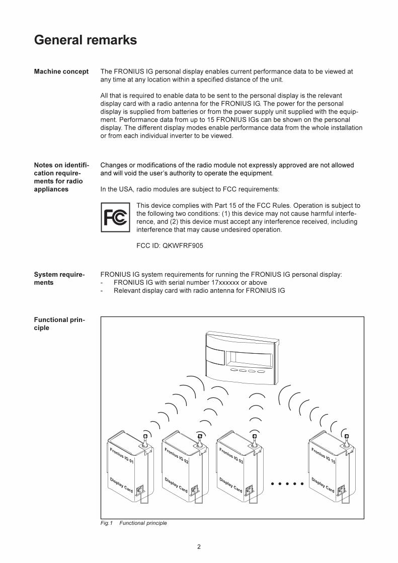
Machine concept The FRONIUS IG personal display enables current performance data to be viewed at
any time at any location within a specified distance of the unit.
All that is required to enable data to be sent to the personal display is the relevant
display card with a radio antenna for the FRONIUS IG. The power for the personal
display is supplied from batteries or from the power supply unit supplied with the equip-
ment. Performance data from up to 15 FRONIUS IGs can be shown on the personal
display. The different display modes enable performance data from the whole installation
or from each individual inverter to be viewed.
System require-
ments
FRONIUS IG system requirements for running the FRONIUS IG personal display:
- FRONIUS IG with serial number 17xxxxxx or above
- Relevant display card with radio antenna for FRONIUS IG
Functional prin-
ciple
Fig.1 Functional principle
Notes on identifi-
cation require-
ments for radio
appliances
Changes or modifications of the radio module not expressly approved are not allowed
and will void the user’s authority to operate the equipment.
In the USA, radio modules are subject to FCC requirements:
This device complies with Part 15 of the FCC Rules. Operation is subject to
the following two conditions: (1) this device may not cause harmful interfe-
rence, and (2) this device must accept any interference received, including
interference that may cause undesired operation.
FCC ID: QKWFRF905
3
System components
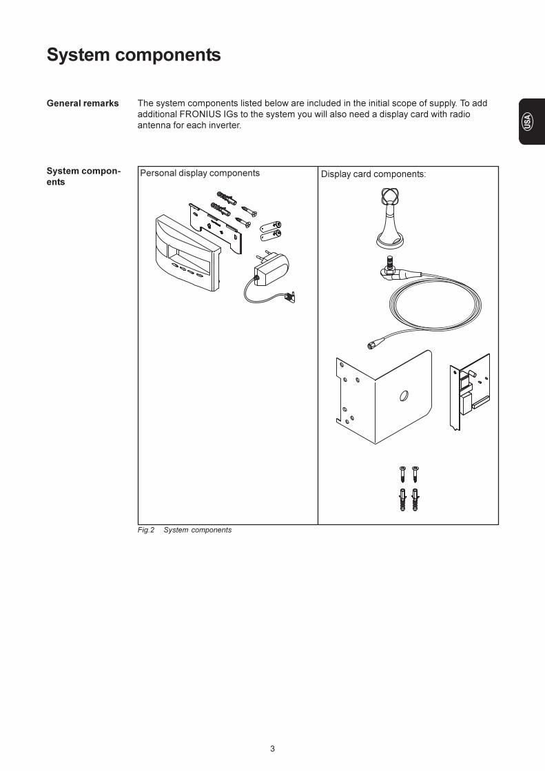
General remarks The system components listed below are included in the initial scope of supply. To add
additional FRONIUS IGs to the system you will also need a display card with radio
antenna for each inverter.
System compon-
ents
Fig.2 System components
Personal display components Display card components:
4
Before commissioning
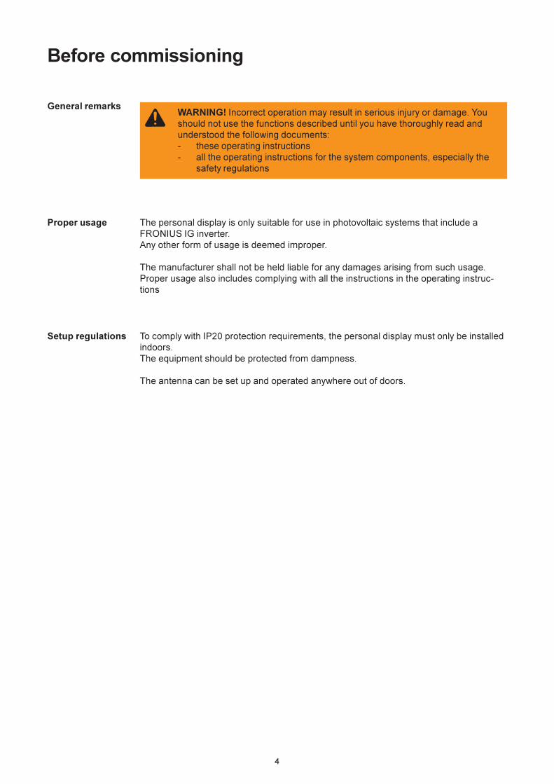
General remarksWARNING! Incorrect operation may result in serious injury or damage. You
should not use the functions described until you have thoroughly read and
understood the following documents:
- these operating instructions
- all the operating instructions for the system components, especially the
safety regulations
Proper usage The personal display is only suitable for use in photovoltaic systems that include a
FRONIUS IG inverter.
Any other form of usage is deemed improper.
The manufacturer shall not be held liable for any damages arising from such usage.
Proper usage also includes complying with all the instructions in the operating instruc-
tions
Setup regulations To comply with IP20 protection requirements, the personal display must only be installed
indoors.
The equipment should be protected from dampness.
The antenna can be set up and operated anywhere out of doors.
5
Preparing your FRONIUS IG for commissioning
General remarksWARNING! Mains voltage can cause fatal injuries. The connection area
should only ever be opened by an authorised electrical engineer, and only
when the power is disconnected.
WARNING! Mains voltage and DC voltage from the solar modules can cause
fatal injuries. Plug-in cards must not be installed unless the FRONIUS IG
- has been disconnected on the mains (AC) side.
- has been disconnected on the solar module side (DC side)
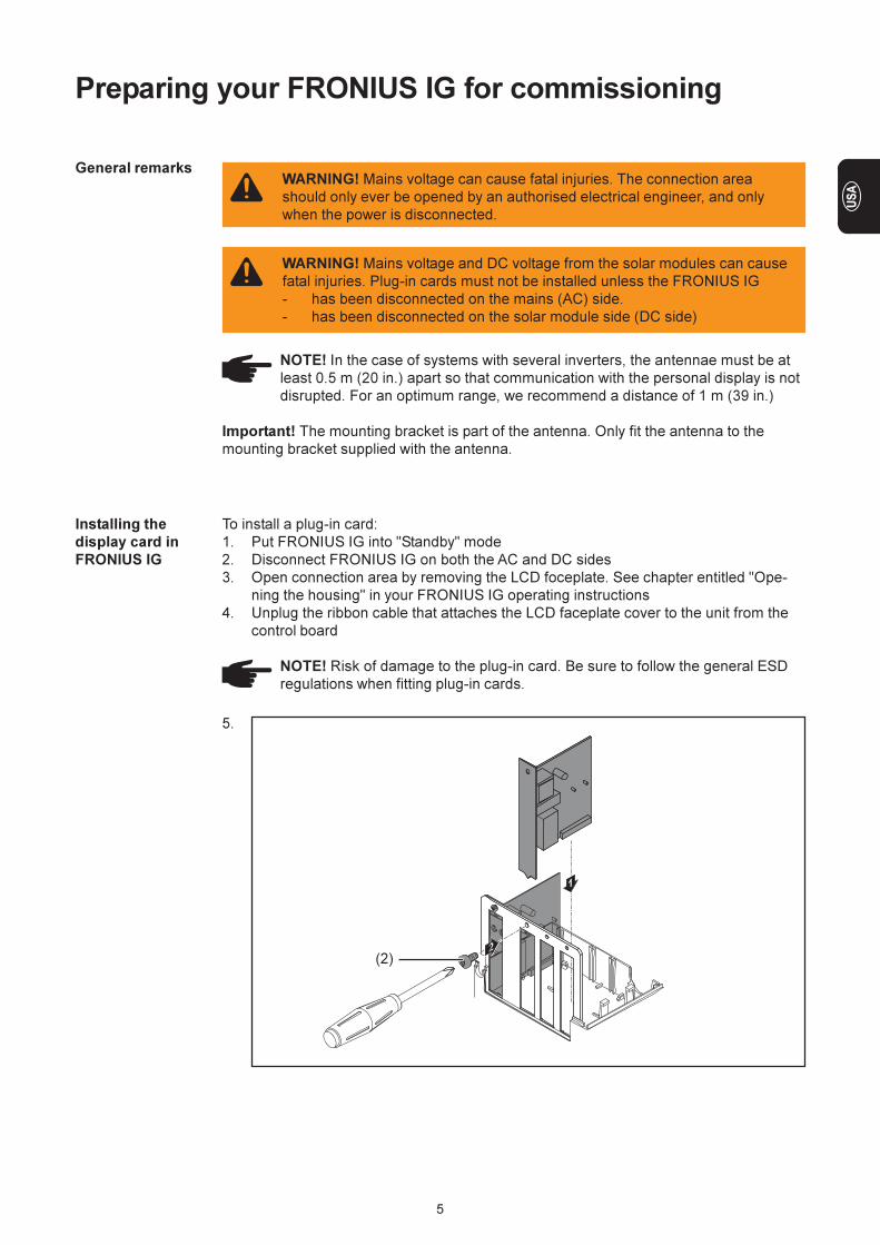
To install a plug-in card:
1. Put FRONIUS IG into "Standby" mode
2. Disconnect FRONIUS IG on both the AC and DC sides
3. Open connection area by removing the LCD foceplate. See chapter entitled "Ope-
ning the housing" in your FRONIUS IG operating instructions
4. Unplug the ribbon cable that attaches the LCD faceplate cover to the unit from the
control board
NOTE! Risk of damage to the plug-in card. Be sure to follow the general ESD
regulations when fitting plug-in cards.
Installing the
display card in
FRONIUS IG
5.
NOTE! In the case of systems with several inverters, the antennae must be at
least 0.5 m (20 in.) apart so that communication with the personal display is not
disrupted. For an optimum range, we recommend a distance of 1 m (39 in.)
Important! The mounting bracket is part of the antenna. Only fit the antenna to the
mounting bracket supplied with the antenna.
(2)
6
Installing/connec-
ting the antenna
Installing the
display card in
FRONIUS IG
(continued)
NOTE! The following points should be borne in mind when installing the display
card:
- Only install the display card in the "Option 1" or "Option 2" slots
- Under no circumstances should it be installed in the slot on the extreme
left, which is labelled ENS
7. Close the housing
8. Connect AC and DC lines to FRONIUS IG
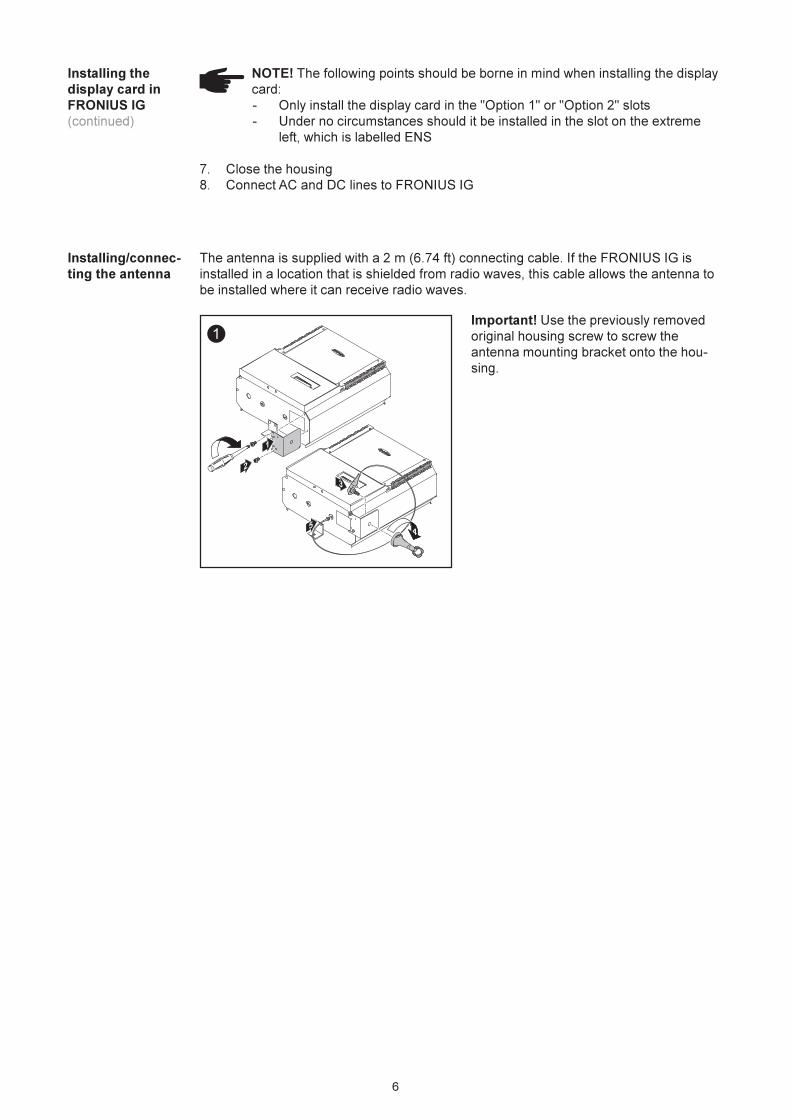
The antenna is supplied with a 2 m (6.74 ft) connecting cable. If the FRONIUS IG is
installed in a location that is shielded from radio waves, this cable allows the antenna to
be installed where it can receive radio waves.
1
45
3
1
2
Important! Use the previously removed
original housing screw to screw the
antenna mounting bracket onto the hou-
sing.
7
Controls
General remarks
The personal display enables performance data for the entire installation and for each
individual inverter to be displayed. The menu structure is largely identical to that of the
FRONIUS IG.
NOTE! As a result of firmware updates, you may find that there are functions
available on your unit that are not described in these operating instructions or
vice versa. Certain illustrations may also differ slightly from the actual controls
on your unit. However, the functionality of these controls is identical.
Description of
keys and sym-
bols
The personal display is modelled on the display of your FRONIUS IG. A detailed descrip-
tion of how the different keys operate and the symbols can be found in the operating
instructions for your FRONIUS IG.
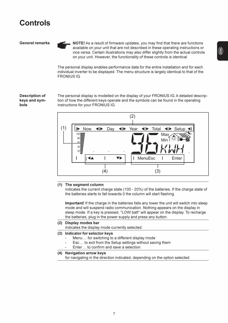
(1)
(1) The segment column
indicates the current charge state (100 - 20%) of the batteries. If the charge state of
the batteries starts to fall towards 0 the column will start flashing.
Important! If the charge in the batteries falls any lower the unit will switch into sleep
mode and will suspend radio communication. Nothing appears on the display in
sleep mode. If a key is pressed, "LOW batt" will appear on the display. To recharge
the batteries, plug in the power supply and press any button.
(2) Display modes bar
indicates the display mode currently selected.
(3) Indicator for selector keys
- Menu ... for switching to a different display mode
- Esc ... to exit from the Setup settings without saving them
- Enter ... to confirm and save a selection
(4) Navigation arrow keys
for navigating in the direction indicated, depending on the option selected
(4)
(2)
(3)
8
Commissioning
Initial settings on
the FRONIUS IG
The personal display allows performance data to be displayed for up to 15 inverters. To
enable the personal display to differentiate between the different inverters when more
than one FRONIUS IG is connected, each inverter must be assigned an individual
numeric address.
Important! These numbers must be between 01 and 15 so that the personal display can
identify the inverter. When several inverters are in use, ensure that each of them is
assigned a different number.
For information on setting the IG number see the chapter entitled "The Setup Menu/IG
no." in the FRONIUS IG operating instructions
Installing/setting
up the personal
display
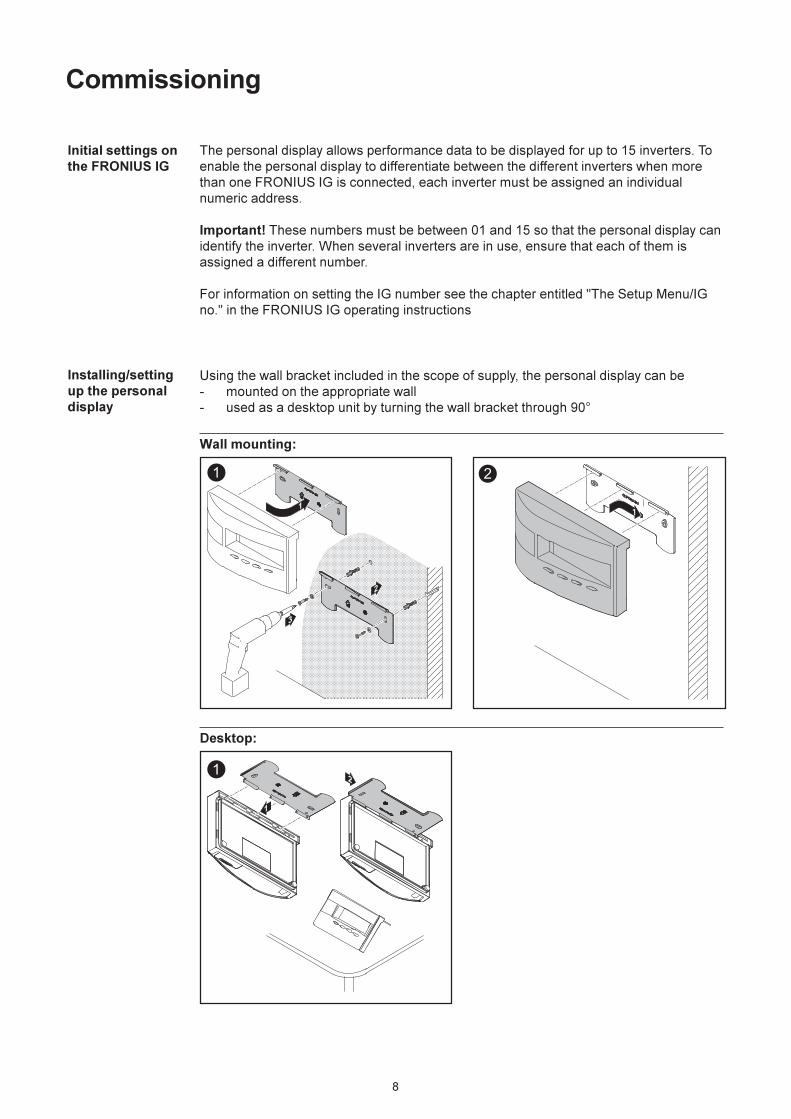
Using the wall bracket included in the scope of supply, the personal display can be
- mounted on the appropriate wall
- used as a desktop unit by turning the wall bracket through 90°
1
2
1
3
12
1
Wall mounting:
Desktop:
9
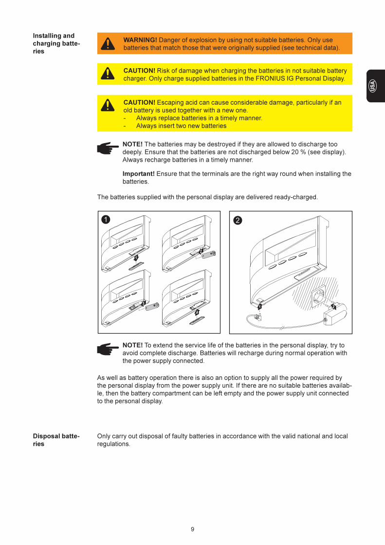
Installing and
charging batte-
ries
Important! Ensure that the terminals are the right way round when installing the
batteries.
The batteries supplied with the personal display are delivered ready-charged.
1
1
2
3
4
2
21
NOTE! To extend the service life of the batteries in the personal display, try to
avoid complete discharge. Batteries will recharge during normal operation with
the power supply connected.
As well as battery operation there is also an option to supply all the power required by
the personal display from the power supply unit. If there are no suitable batteries availab-
le, then the battery compartment can be left empty and the power supply unit connected
to the personal display.
WARNING! Danger of explosion by using not suitable batteries. Only use
batteries that match those that were originally supplied (see technical data).
CAUTION! Risk of damage when charging the batteries in not suitable battery
charger. Only charge supplied batteries in the FRONIUS IG Personal Display.
Disposal batte-
ries
Only carry out disposal of faulty batteries in accordance with the valid national and local
regulations.
NOTE! The batteries may be destroyed if they are allowed to discharge too
deeply. Ensure that the batteries are not discharged below 20 % (see display).
Always recharge batteries in a timely manner.
CAUTION! Escaping acid can cause considerable damage, particularly if an
old battery is used together with a new one.
- Always replace batteries in a timely manner.
- Always insert two new batteries
10
The personal display is now ready to display all the performance data for your installati-
on.
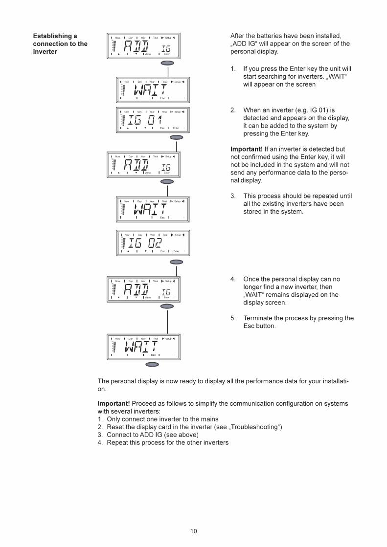
Establishing a
connection to the
inverter
After the batteries have been installed,
„ADD IG“ will appear on the screen of the
personal display.
1. If you press the Enter key the unit will
start searching for inverters. „WAIT“
will appear on the screen
2. When an inverter (e.g. IG 01) is
detected and appears on the display,
it can be added to the system by
pressing the Enter key.
Important! If an inverter is detected but
not confirmed using the Enter key, it will
not be included in the system and will not
send any performance data to the perso-
nal display.
3. This process should be repeated until
all the existing inverters have been
stored in the system.
4. Once the personal display can no
longer find a new inverter, then
„WAIT“ remains displayed on the
display screen.
5. Terminate the process by pressing the
Esc button.
Important! Proceed as follows to simplify the communication configuration on systems
with several inverters:
1. Only connect one inverter to the mains
2. Reset the display card in the inverter (see „Troubleshooting“)
3. Connect to ADD IG (see above)
4. Repeat this process for the other inverters
11
General remarks The personal display has display modes that are similar to those of the FRONIUS IG. A
detailed description of the display values can be found in the FRONIUS IG operating
instructions.
The personal display’s independent power supply enables performance data to be
retrieved even after the onset of dusk.
During the day, the default display mode for the personal display is „Now“. After the
onset of dusk the FRONIUS IG will disconnect from the mains and the personal display
will switch to „Day“ display mode.
Operating scheme
Display Press any key to activate the display. If no key is pressed for 10 seconds or more, the
display illumination will go off again.
To save battery power, the display will switch to sleep mode after a specified delay. The
display then goes off, but can be reactivated by pressing any key. The specified delay
until energy saving mode begins can be modified in the setup menu. Sleep mode can
also be switched off entirely.
For information on general display settings see the chapter entitled „The Set-up menu“
Display modes By default, all the performance data for all the FRONIUS IGs in the system is shown in
„Now“ display mode. If there is more than one inverter in the system (up to 15 are
possible), then the performance data for each individual inverter can be retrieved.
The following display modes are available for performance data for:
- the complete installation
- each separate FRONIUS IG in the system
„Now“ display mode
Displays real-time values
„Day“ display mode
Displays values for power fed into the mains during that day
„Year“ display mode (only in conjunction with a datalogger)
Displays values for power fed into the mains during that calendar year
„Total“ display mode
Displays values for power fed into the mains since the system was first commissioned
Important! If no key is pressed for 2 minutes, the unit will switch back automatically into
„Now“ display mode and will display performance data for the entire installation.
12
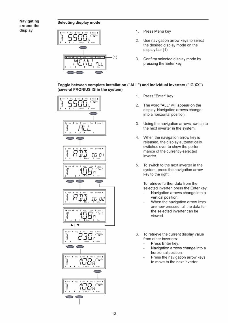
Navigating
around the
display
Selecting display mode
Toggle between complete installation ("ALL") and individual inverters ("IG XX")
(several FRONIUS IG in the system)
1. Press Menu key
2. Use navigation arrow keys to select
the desired display mode on the
display bar (1)
3. Confirm selected display mode by
pressing the Enter key.
(1)
1. Press "Enter" key
2. The word "ALL" will appear on the
display. Navigation arrows change
into a horizontal position.
3. Using the navigation arrows, switch to
the next inverter in the system.
4. When the navigation arrow key is
released, the display automatically
switches over to show the perfor-
mance of the currently-selected
inverter.
5. To switch to the next inverter in the
system, press the navigation arrow
key to the right.
To retrieve further data from the
selected inverter, press the Enter key:
- Navigation arrows change into a
vertical position.
- When the navigation arrow keys
are now pressed, all the data for
the selected inverter can be
viewed.
6. To retrieve the current display value
from other inverters:
- Press Enter key.
- Navigation arrows change into a
horizontal position.
- Press the navigation arrow keys
to move to the next inverter.
13
Navigating
around the
display
(continued)
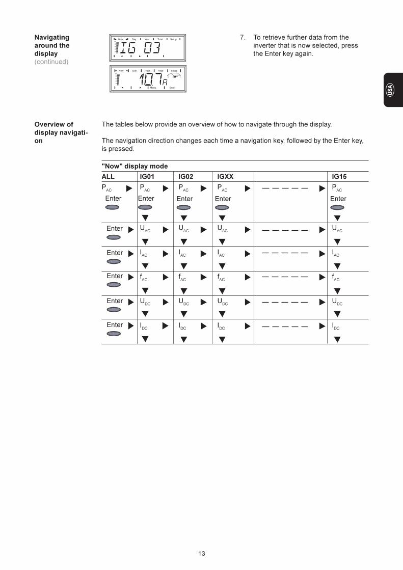
7. To retrieve further data from the
inverter that is now selected, press
the Enter key again.
Overview of
display navigati-
on
The tables below provide an overview of how to navigate through the display.
The navigation direction changes each time a navigation key, followed by the Enter key,
is pressed.
"Now" display mode
ALL IG01 IG02 IGXX IG15
PAC
PAC
PAC
PAC
PAC
UAC
UAC
UAC
UAC
IAC
IAC
IAC
IAC
fAC
fAC
fAC
fAC
UDC
UDC
UDC
UDC
IDC
IDC
IDC
IDC
Enter Enter Enter Enter
Enter
Enter
Enter
Enter
Enter
Enter
14
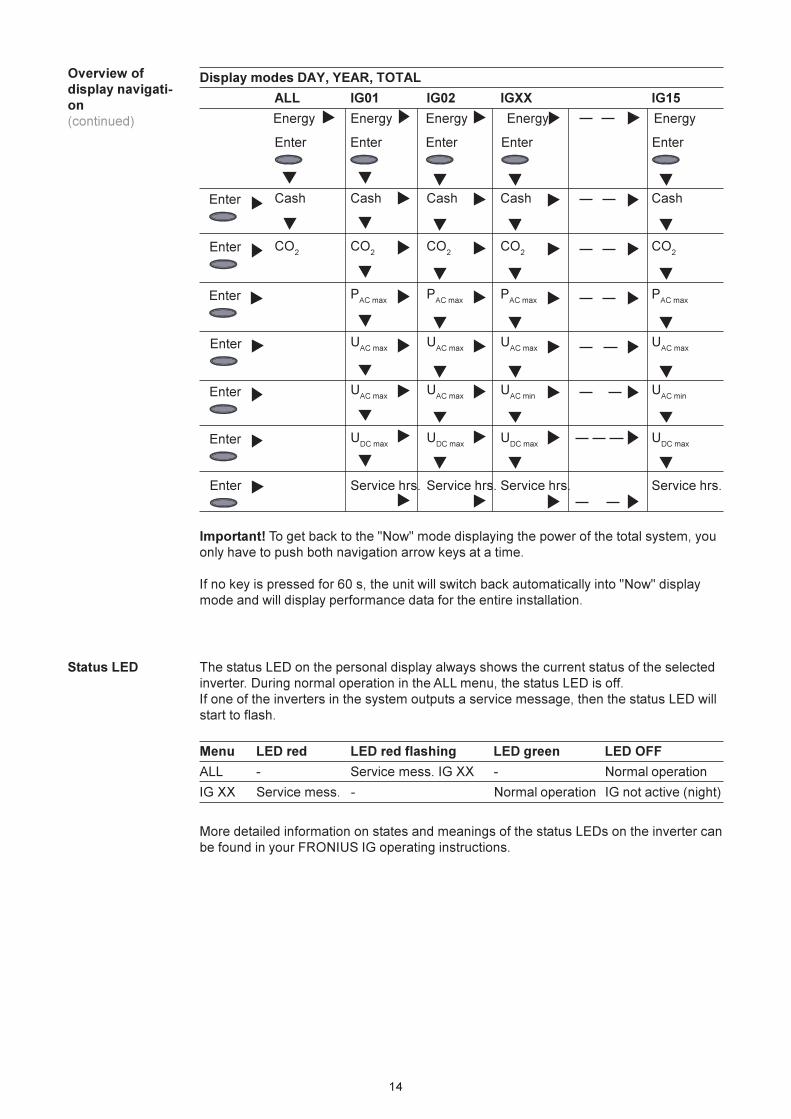
Important! To get back to the "Now" mode displaying the power of the total system, you
only have to push both navigation arrow keys at a time.
If no key is pressed for 60 s, the unit will switch back automatically into "Now" display
mode and will display performance data for the entire installation.
Display modes DAY, YEAR, TOTAL
ALL IG01 IG02 IGXX IG15
Energy Energy Energy Energy Energy
Cash Cash Cash Cash Cash
CO2
CO2
CO2
CO2
CO2
PAC max
PAC max
PAC max
PAC max
UAC max
UAC max
UAC max
UAC max
UAC max
UAC max
UAC min
UAC min
UDC max
UDC max
UDC max
UDC max
Service hrs. Service hrs. Service hrs. Service hrs.
Overview of
display navigati-
on
(continued)
Enter Enter Enter EnterEnter
Enter
Enter
Enter
Enter
Enter
Enter
Enter
Status LED The status LED on the personal display always shows the current status of the selected
inverter. During normal operation in the ALL menu, the status LED is off.
If one of the inverters in the system outputs a service message, then the status LED will
start to flash.
Menu LED red LED red flashing LED green LED OFF
ALL - Service mess. IG XX - Normal operation
IG XX Service mess. - Normal operation IG not active (night)
More detailed information on states and meanings of the status LEDs on the inverter can
be found in your FRONIUS IG operating instructions.
15
The Setup menu
General remarks The setup menu allows initial settings to be made for operating the personal display. The
inverter’s setup parameters cannot be accessed.
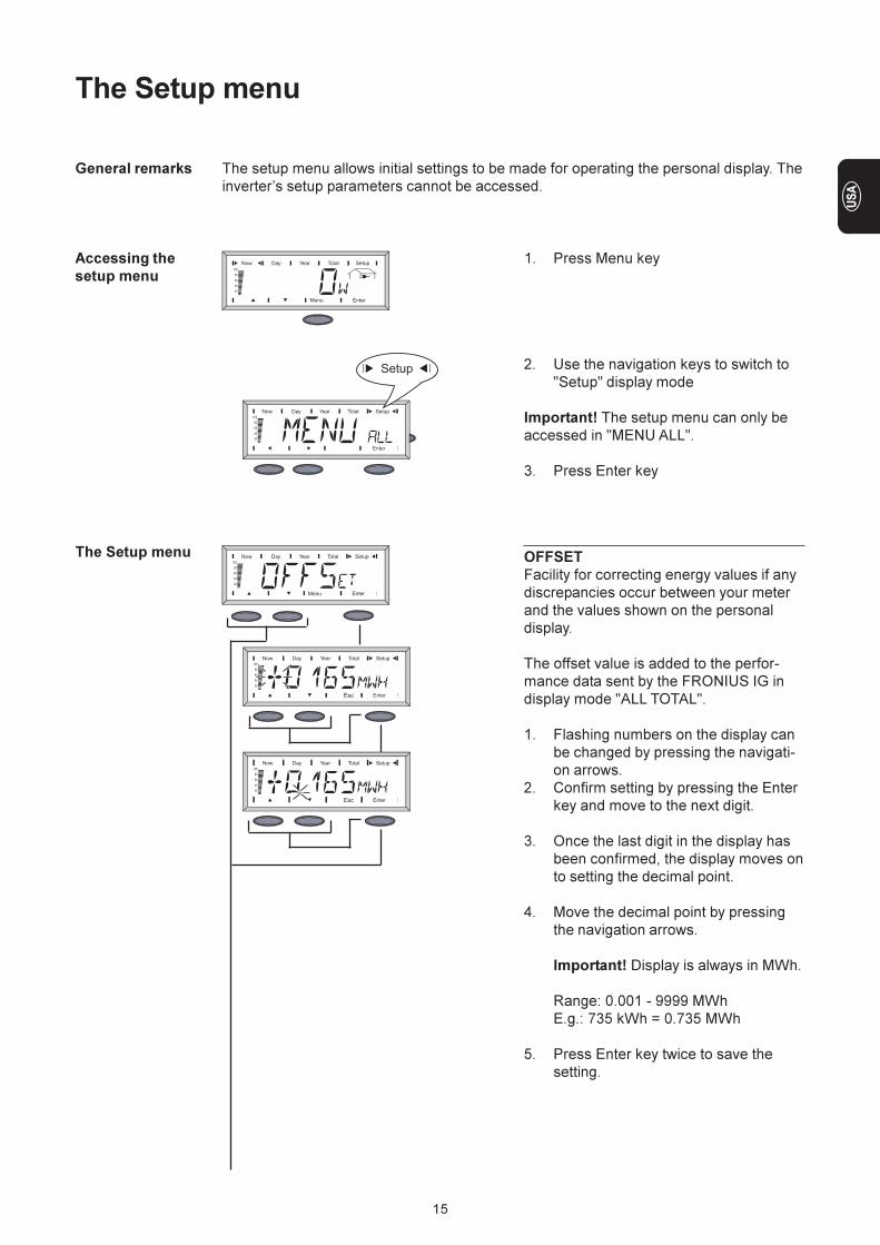
Accessing the
setup menu
1. Press Menu key
2. Use the navigation keys to switch to
"Setup" display mode
Important! The setup menu can only be
accessed in "MENU ALL".
3. Press Enter key
The Setup menu OFFSET
Facility for correcting energy values if any
discrepancies occur between your meter
and the values shown on the personal
display.
The offset value is added to the perfor-
mance data sent by the FRONIUS IG in
display mode "ALL TOTAL".
1. Flashing numbers on the display can
be changed by pressing the navigati-
on arrows.
2. Confirm setting by pressing the Enter
key and move to the next digit.
3. Once the last digit in the display has
been confirmed, the display moves on
to setting the decimal point.
4. Move the decimal point by pressing
the navigation arrows.
Important! Display is always in MWh.
Range: 0.001 - 9999 MWh
E.g.: 735 kWh = 0.735 MWh
5. Press Enter key twice to save the
setting.
16
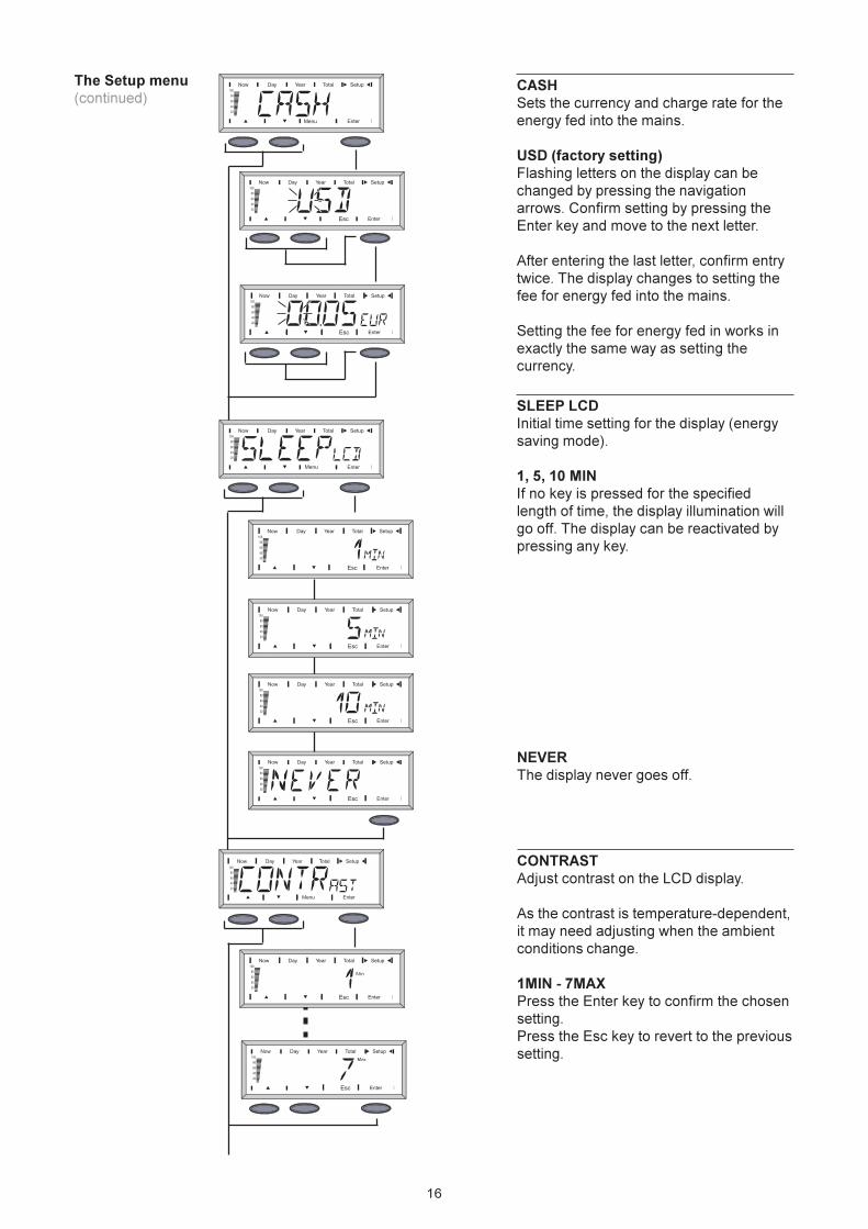
The Setup menu
(continued)CASH
Sets the currency and charge rate for the
energy fed into the mains.
USD (factory setting)
Flashing letters on the display can be
changed by pressing the navigation
arrows. Confirm setting by pressing the
Enter key and move to the next letter.
After entering the last letter, confirm entry
twice. The display changes to setting the
fee for energy fed into the mains.
Setting the fee for energy fed in works in
exactly the same way as setting the
currency.
SLEEP LCD
Initial time setting for the display (energy
saving mode).
1, 5, 10 MIN
If no key is pressed for the specified
length of time, the display illumination will
go off. The display can be reactivated by
pressing any key.
NEVER
The display never goes off.
CONTRAST
Adjust contrast on the LCD display.
As the contrast is temperature-dependent,
it may need adjusting when the ambient
conditions change.
1MIN - 7MAX
Press the Enter key to confirm the chosen
setting.
Press the Esc key to revert to the previous
setting.
17
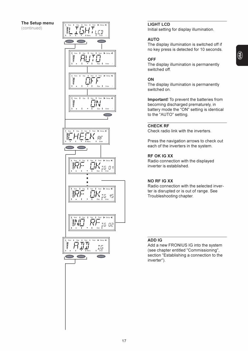
LIGHT LCD
Initial setting for display illumination.
AUTO
The display illumination is switched off if
no key press is detected for 10 seconds.
OFF
The display illumination is permanently
switched off.
ON
The display illumination is permanently
switched on.
Important! To prevent the batteries from
becoming discharged prematurely, in
battery mode the "ON" setting is identical
to the "AUTO" setting.
CHECK RF
Check radio link with the inverters.
Press the navigation arrows to check out
each of the inverters in the system.
RF OK IG XX
Radio connection with the displayed
inverter is established.
NO RF IG XX
Radio connection with the selected inver-
ter is disrupted or is out of range. See
Troubleshooting chapter.
ADD IG
Add a new FRONIUS IG into the system
(see chapter entitled "Commissioning",
section "Establishing a connection to the
inverter").
The Setup menu
(continued)
18
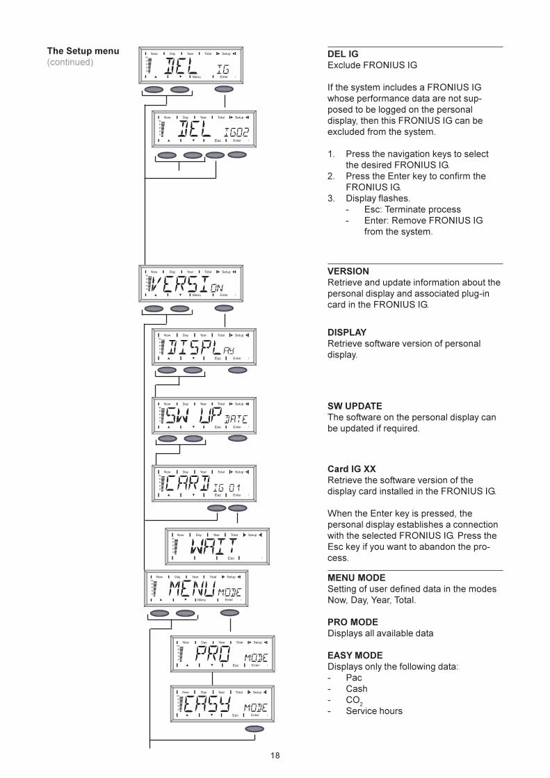
DEL IG
Exclude FRONIUS IG
If the system includes a FRONIUS IG
whose performance data are not sup-
posed to be logged on the personal
display, then this FRONIUS IG can be
excluded from the system.
1. Press the navigation keys to select
the desired FRONIUS IG.
2. Press the Enter key to confirm the
FRONIUS IG.
3. Display flashes.
- Esc: Terminate process
- Enter: Remove FRONIUS IG
from the system.
VERSION
Retrieve and update information about the
personal display and associated plug-in
card in the FRONIUS IG.
DISPLAY
Retrieve software version of personal
display.
SW UPDATE
The software on the personal display can
be updated if required.
Card IG XX
Retrieve the software version of the
display card installed in the FRONIUS IG.
When the Enter key is pressed, the
personal display establishes a connection
with the selected FRONIUS IG. Press the
Esc key if you want to abandon the pro-
cess.
The Setup menu
(continued)
MENU MODE
Setting of user defined data in the modes
Now, Day, Year, Total.
PRO MODE
Displays all available data
EASY MODE
Displays only the following data:
- Pac
- Cash
- CO2
- Service hours
19
Troubleshooting
General remarks
Troubleshooting
The display shows error messages if a fault or error occurs
- on a FRONIUS IG in the system
- on the personal display
If a FRONIUS IG in the system sends a service message, the personal display will
indicate it through its status LED, which will flash red.
To find out which inverter is affected:
- Press Enter key
- Use the left/right navigation arrows to scroll through the inverters in the system. The
status LED of any inverter displaying a service message will be steady red. The
display will also show the service code, which is also output on the FRONIUS IG
itself. Information on the service codes can be found in your FRONIUS IG operating
instructions.
IG XX MISS / NO RF IG XX (Check RF following prompt)
Cause: Connection to inverter has been lost or is out of range.
Remedy: Check antenna connection.
Cause: No power supply to display card in the inverter
Remedy: Check AC connection of FRONIUS IG. Check fuse on display card
and change if necessary.
IG XX MISS / RF OK (Check RF following prompt)
Cause: Connection to inverter is OK. Power supply to inverter has been lost
on the DC side. After sunset the inverter disconnects itself from the
mains.
Remedy: Wait for sunrise.
Cause: Connection between FRONIUS IG and solar modules has been lost
Remedy: Check connection between FRONIUS IG and solar modules.
Personal display does not find all FRONIUS IGs in „ADD IG“ search mode
Cause: The FRONIUS IGs have not been assigned unique numbers.
Remedy: Check numbers on the inverters and correct them if necessary.
Cause: FRONIUS IG is out of radio range.
Remedy: Check radio range
ERROR IG XX
in "ADD IG" search mode
Cause: FRONIUS IG address number is greater than 15
Remedy: Check number on the inverter and correct it if necessary.
ADD IG -- (at search mode „ADD IG“)
Cause: Power supply to inverter has been lost on the DC side
Remedy: Check power supply of FRONIUS IG on the DC side
20
Power supply
Battery 2 x 1.5 V RAM batteries (1800 mAh)
Power supply unit 9 VDC
; 0,5 A
Protection NEMA1; IP 20
Operating temperature 0 - 40° C
32 - 104° F
Frequency range 915 MHz
Radio range up to 300 m in the open
Dimensions 190 x 114 x 53 mm
7.48 x 4.49 x 2.09 in.
Power supply 240 VAC/
/ 208 VAC/
Protection class of plug-in card (installed in the FRONIUS IG)
see FRONIUS IG operating instructions
Plug-in card operating temperature -20 to +50° C
-4 to 122° F
Frequency range 915 MHz
Dimensions 140 x 100 x 26 mm
5.51 x 3.94 x 1.02 in.
Personal display
Plug-in card
Technical data
Troubleshooting
(continued)ERROR BATT
Power supply connected, battery charging
Cause: Wrong or faulty batteries installed.
Remedy: Check batteries
FULL LIST
in „ADD IG“ search mode
Cause: There are already 15 FRONIUS IGs in the system.
No communication is possible between the personal display and the FRONIUS IG
Cause: Only one personal display can ever communicate with the FRONIUS
IGs in the system.
Remedy: If the personal display is replaced with a new one, then all the
FRONIUS IGs in the system should be deleted from the personal
display’s configuration (see "The Setup menu", section "DEL IG").
NOTE! If the inverters in the system have not been deleted from the configurati-
on of the personal display and if the personal display used previously is no
longer available (because of damage, for instance), then the display card in the
FRONIUS IG must be reset.
Resetting the display card on the FRONIUS IG:
1. Open the setup menu and choose "DatCom"
2. Use arrow keys to move to the "PDCD RST" menu item
3. Press the Enter key to reset the display card
21
The warranty in the general terms of business applies to the FRONIUS IG DatCom
components. During this period, FRONIUS guarantees that your DatCom components
will work correctly. If there is a defect for which FRONIUS is responsible, then FRONIUS
will repair the defect at the factory free of charge within the warranty period.
If you need to claim under the warranty, please contact your FRONIUS dealer.
Warranty claims will not be accepted as a result of:
- using your DatCom components for other than the intended purpose
- incorrect installation or installation not in compliance with the applicable standards,
particularly by unlicensed electrical fitters
- incorrect operation
- unauthorised changes to the DatCom components
- damage by foreign objects or acts of God (force majeure)
Warranty claims will be repaired either by Fronius directly or locally by Fronius trained
service partners. For return transportation, devices must be packed in their original or
equivalent packaging.
These services will be charged to the dealer or his fitter, as will the reinstallation of the
repaired device.
The warranty only covers the DatCom components. The other components of your
photovoltaic system and the supplied rechargeable batteries are not covered by the
warranty.
Purchase date on the invoice, date on which the device was handed over / commissio-
ned and report from the electricity supply company.
24 months from the date of installation.
Warranty and Liability
Warranty Provisi-
ons and Liability
Scope of Warran-
ty
Warranty Period
Proof of warranty

ud_fr_se_so_00913 022005
Fronius International GmbH
4600 Wels-Thalheim, Günter-Fronius-Straße 1, Austria
E-Mail: [email protected]
http://www.fronius.com
USAA
Fronius Worldwide - www.fronius.com/addresses
Fronius USA LLC Solar Electronic Division
5266 Hollister Ave., #117, Santa Barbara, California 93111
E-Mail: [email protected]
http://www.fronius-usa.com
Under http://www.fronius.com/addresses you will find all addresses of our sales branches and partner firms!


