
http://www.axcontrol.com/automation/pro-face/gp-4000
PFXGP4601TMD
1-800-991-7026
See Also:
http://www.axcontrol.com/automation/pro-face/gp-4000/PFXGP4601TMD
Pro-face Xycom GP4000
PFXGP4601TMD
Pro-face Xycom GP-460xT GP460xT
Touch Screen Operator Interface 12.1 TFT Analog Color LCD Display 2 x Serial. Call Now!
Specifications
50
Memory, Clock, and Touch Panel
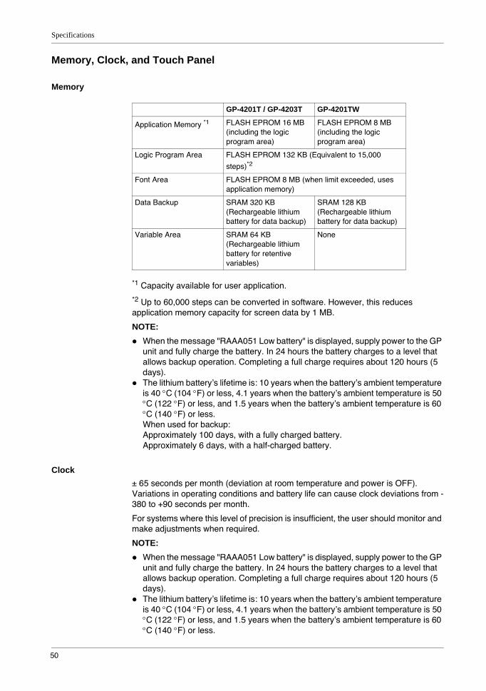
Memory
*1 Capacity available for user application.
*2 Up to 60,000 steps can be converted in software. However, this reduces application memory capacity for screen data by 1 MB.
NOTE: When the message "RAAA051 Low battery" is displayed, supply power to the GP unit and fully charge the battery. In 24 hours the battery charges to a level that allows backup operation. Completing a full charge requires about 120 hours (5 days).The lithium battery’s lifetime is: 10 years when the battery’s ambient temperature is 40 °C (104 °F) or less, 4.1 years when the battery’s ambient temperature is 50 °C (122 °F) or less, and 1.5 years when the battery’s ambient temperature is 60 °C (140 °F) or less.When used for backup:Approximately 100 days, with a fully charged battery.Approximately 6 days, with a half-charged battery.
Clock± 65 seconds per month (deviation at room temperature and power is OFF). Variations in operating conditions and battery life can cause clock deviations from -380 to +90 seconds per month.
For systems where this level of precision is insufficient, the user should monitor and make adjustments when required.
NOTE: When the message "RAAA051 Low battery" is displayed, supply power to the GP unit and fully charge the battery. In 24 hours the battery charges to a level that allows backup operation. Completing a full charge requires about 120 hours (5 days).The lithium battery’s lifetime is: 10 years when the battery’s ambient temperature is 40 °C (104 °F) or less, 4.1 years when the battery’s ambient temperature is 50 °C (122 °F) or less, and 1.5 years when the battery’s ambient temperature is 60 °C (140 °F) or less.
GP-4201T / GP-4203T GP-4201TW
Application Memory *1 FLASH EPROM 16 MB (including the logic program area)
FLASH EPROM 8 MB (including the logic program area)
Logic Program Area FLASH EPROM 132 KB (Equivalent to 15,000
steps)*2
Font Area FLASH EPROM 8 MB (when limit exceeded, uses application memory)
Data Backup SRAM 320 KB (Rechargeable lithium battery for data backup)
SRAM 128 KB (Rechargeable lithium battery for data backup)
Variable Area SRAM 64 KB (Rechargeable lithium battery for retentive variables)
None

GP4000 Series Hardware Manual
51
When used for backup:Approximately 100 days, with a fully charged battery.Approximately 6 days, with a half-charged battery.
Touch Panel
Touch Panel Type Resistive Film (analog)
Touch Panel Resolution 1,024 x 1,024
Touch Panel Service Life 1 million times or more

Specifications
52
Interface Specifications
Serial Interface COM1
Serial Interface COM2
USB Interface
Ethernet Interface
NOTE: GP-4201TW does not have an Ethernet interface.
GP-4201T GP-4201TW GP-4203T
Asynchronous Transmission
RS-232C / RS-422 / RS-485
RS-232C RS-485 (isolation)
Data Length 7 or 8 bits
Stop Bit 1 or 2 bits
Parity None, odd or even
Data Transmission Speed
2,400...115,200 bps, 187,500 bps (MPI)
2,400...115,200 bps 2,400...115,200 bps, 187,500 bps (MPI)
Connector D-Sub 9 pin (plug) D-Sub 9 pin (socket)
GP-4201TW
Asynchronous Transmission RS-422 / RS-485
Data Length 7 or 8 bits
Stop Bit 1 or 2 bits
Parity None, odd or even
Data Transmission Speed 2,400...115,200 bps, 187,500 bps (MPI)
Connector D-Sub 9 pin (plug)
USB (Type A) Interface USB (mini-B) Interface
Connector USB 2.0 (Type A) x 1 USB 2.0 (mini-B) x 1
Power Supply Voltage 5 Vdc ±5% -
Maximum Current Supplied
500 mA -
Maximum Transmission Distance
5 m (16.4 ft)
GP-4201T / GP-4203T
Ethernet (LAN) IEEE802.3i / IEEE802.3u, 10BASE-T/100BASE-TX
Connector Modular jack (RJ45) x 1
GP4000 Series Hardware Manual
53
Specifications of Serial Interface COM1
IntroductionNOTE: For instructions on how to connect to other devices, always refer to the “GP-Pro EX Device/PLC Connection Manual”.
The COM1 ports of GP-4201T and GP-4201TW are not isolated. The SG (signal ground) and FG (frame ground) terminals are connected inside the GP unit.
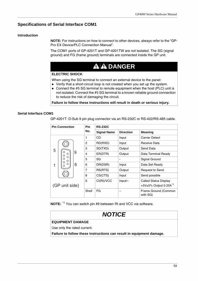
Serial Interface COM1GP-4201T: D-Sub 9 pin plug connector via an RS-232C or RS-422/RS-485 cable.
NOTE: *1 You can switch pin #9 between RI and VCC via software.
DANGERELECTRIC SHOCKWhen using the SG terminal to connect an external device to the panel:
Verify that a short-circuit loop is not created when you set up the system.Connect the #5 SG terminal to remote equipment when the host (PLC) unit is not isolated. Connect the #5 SG terminal to a known reliable ground connection to reduce the risk of damaging the circuit.
Failure to follow these instructions will result in death or serious injury.
Pin Connection Pin No.
RS-232C
Signal Name Direction Meaning
1 CD Input Carrier Detect
2 RD(RXD) Input Receive Data
3 SD(TXD) Output Send Data
4 ER(DTR) Output Data Terminal Ready
5 SG - Signal Ground
6 DR(DSR) Input Data Set Ready
7 RS(RTS) Output Request to Send
8 CS(CTS) Input Send possible
9 CI(RI)/VCC Input/– Called Status Display
+5V±5% Output 0.25A*1
Shell FG – Frame Ground (Common with SG)
NOTICEEQUIPMENT DAMAGEUse only the rated current.
Failure to follow these instructions can result in equipment damage.
9
6
5
1
(GP unit side)

Specifications
54
Interfit bracket is #4-40 (UNC).
Recommendations:Cable Connector: XM2D-0901 manufactured by OMRON Corporation.Cable Cover: XM2S-0913 manufactured by OMRON Corporation.Jack Screw (#4-40 UNC): XM2Z-0073 manufactured by OMRON Corporation.
GP-4201TW: D-Sub 9 pin plug connector via an RS-232C cable.
NOTE: *1 You can switch pin #9 between RI and VCC via software.
Pin Connection Pin No.
RS-422/RS-485
Signal Name Direction Meaning
1 RDA Input Receive Data A (+)
2 RDB Input Receive Data B (-)
3 SDA Output Send Data A (+)
4 ERA Output Data Terminal Ready A (+)
5 SG - Signal Ground
6 CSB Input Send Possible B (-)
7 SDB Output Send Data B (-)
8 CSA Input Send Possible A (+)
9 ERB Output Data Terminal Ready B (-)
Shell FG – Frame Ground (Common with SG)
CAUTIONLOSS OF COMMUNICATION
All connections to the communication ports must not put excessive stress on the ports.Securely attach communication cables to the panel wall or cabinet.Use only D-Sub 9 pin cables with a locking tab in good condition.
Failure to follow these instructions can result in injury or equipment damage.
Pin Connection Pin No.
RS-232C
Signal Name Direction Meaning
1 CD Input Carrier Detect
2 RD(RXD) Input Receive Data
3 SD(TXD) Output Send Data
4 ER(DTR) Output Data Terminal Ready
5 SG - Signal Ground
6 DR(DSR) Input Data Set Ready
7 RS(RTS) Output Request to Send
8 CS(CTS) Input Send possible
9 CI(RI)/VCC Input/– Called Status Display
+5V±5% Output 0.25A*1
Shell FG – Frame Ground (Common with SG)
9
6
5
1
(GP unit side)
9
6
5
1
(GP unit side)

GP4000 Series Hardware Manual
55
Interfit bracket is #4-40 (UNC).
Recommendations:Cable Connector: XM2D-0901 manufactured by OMRON Corporation.Cable Cover: XM2S-0913 manufactured by OMRON Corporation.Jack Screw (#4-40 UNC): XM2Z-0073 manufactured by OMRON Corporation.
GP-4203T: D-Sub 9 pin socket connector via a RS-485, PROFIBUS, or MPI cable.
NOTE: *1 You can supply power to the Siemens PROFIBUS connector only. You cannot supply power to the device/PLC.
*2 The SG and FG terminals are isolated.
Interfit bracket is #4-40 (UNC).
Recommendations:Cable Connector: XM2A-0901 manufactured by OMRON Corporation.Cable Cover: XM2S-0913 manufactured by OMRON Corporation.Jack Screw (#4-40 UNC): XM2Z-0073 manufactured by OMRON Corporation.
NOTICEEQUIPMENT DAMAGEUse only the rated current.
Failure to follow these instructions can result in equipment damage.
CAUTIONLOSS OF COMMUNICATION
All connections to the communication ports must not put excessive stress on the ports.Securely attach communication cables to the panel wall or cabinet.Use only D-Sub 9 pin cables with a locking tab in good condition.
Failure to follow these instructions can result in injury or equipment damage.
Pin Connection Pin No.
RS-485 (isolation)
Signal Name Direction Meaning
1 NC – no connection
2 NC – no connection
3 Line A Input/Output Data A (+)
4 RS(RTS) Output Request to Send
5 SG – Signal Ground
6 VCC – +5V±5% External Output*1
7 NC – no connection
8 Line B Input/Output Data B (-)
9 NC – no connection
Shell FG – Frame Ground*2 (Not connected with SG)
6
9
1
5
(GP unit side)

Specifications
56
CAUTIONLOSS OF COMMUNICATION
All connections to the communication ports must not put excessive stress on the ports.Securely attach communication cables to the panel wall or cabinet.Use only D-Sub 9 pin cables with a locking tab in good condition.
Failure to follow these instructions can result in injury or equipment damage.

GP4000 Series Hardware Manual
57
Specifications of Serial Interface COM2
IntroductionNOTE: For instructions on how to connect to other devices, always refer to the “GP-Pro EX Device/PLC Connection Manual”.
The serial port is not isolated. The SG (signal ground) and FG (frame ground) terminals are connected inside the GP unit.
Serial Interface COM2GP-4201TW: D-Sub 9 pin plug connector via an RS-422/485 cable.
Interfit bracket is #4-40 (UNC).
Recommendations:Cable Connector: XM2D-0901 manufactured by OMRON Corporation.Cable Cover: XM2S-0913 manufactured by OMRON Corporation.Jack Screw (#4-40 UNC): XM2Z-0073 manufactured by OMRON Corporation.
DANGERELECTRIC SHOCKWhen using the SG terminal to connect an external device to the panel:
Verify that a short-circuit loop is not created when you set up the system.Connect the #5 SG terminal to remote equipment when the host (PLC) unit is not isolated. Connect the #5 SG terminal to a known reliable ground connection to reduce the risk of damaging the circuit.
Failure to follow these instructions will result in death or serious injury.
Pin Connection Pin No.
RS-422/RS-485
Signal Name Direction Meaning
1 RDA Input Receive Data A (+)
2 RDB Input Receive Data B (-)
3 SDA Output Send Data A (+)
4 ERA Output Data Terminal Ready A (+)
5 SG - Signal Ground
6 CSB Input Send Possible B (-)
7 SDB Output Send Data B (-)
8 CSA Input Send Possible A (+)
9 ERB Output Data Terminal Ready B (-)
Shell FG – Frame Ground (Common with SG)
CAUTIONLOSS OF COMMUNICATION
All connections to the communication ports must not put excessive stress on the ports.Securely attach communication cables to the panel wall or cabinet.Use only D-Sub 9 pin cables with a locking tab in good condition.
Failure to follow these instructions can result in injury or equipment damage.
9
6
5
1
(GP unit side)
Specifications
58
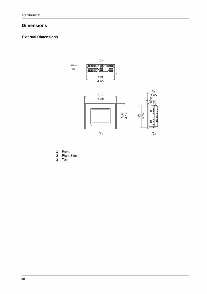
Dimensions
External Dimensions
1 Front2 Right Side3 Top

GP4000 Series Hardware Manual
59
Installation with Installation Fasteners
1 Left Side2 Front3 Right Side4 Top5 Bottom

Specifications
60
Dimensions with Cables: GP-4201T
1 Left Side2 Rear3 Right Side4 Top5 Bottom
NOTE: All the above values are designed with cable bending in mind. The dimensions given here are representative values depending on the type of connection cable in use. Therefore, these values are intended for reference only.
73
(1) (2)
(5)
(4)
(3)
59
94
21
36
mm in.
2.87
1.42
2.32
0.83
3.70


