
PIC-V®, MVP® & PIM
Recommended Applications:
• Wherebalancingatreducedloadsisneeded,suchasofficebuildings,schoolsorhotels
• Wheretemperaturevariancecannotberisked,suchashospitals,laboratoriesorprisons
• Wherelongeractuatorlifeisrequired
• Wheretheprimaryvariableflowsystemneedstobeoptimized
Absolute Control. Optimized Efficiency.

2
Pressure Independent Control Valves
How Does Flow Change?Flow (Q) changes as pressure (P) and/or open area (A) changes. This is represented with the simple formula:
Q = A*√ΔP Where:Q = Flowrate in gpm; A = Open Area; ΔP= Pressure Differential
Flow Change with Pressure Independent ValveIf you maintain a constant pressure (P) drop AND a
constant area (A) the flow (Q) remains unchanged.
Q= A*√ΔPThe actuator rotation moves the horizontal fixed flow line up or down to provide temperature control modulation. Simultaneously, flow control is maintained along the horizontal portion of the graph within the minimum & maximum differential pressure limits when the pressure in the system changes.
Flow Change with a Traditional Actuated ValveIn a traditional Actuated Ball Valve or Actuated Globe Valve as the pressure (P) changes in the system the flowrate (Q) changes through the valve. If the zone was satisfied and now the flow changed the actuator now needs to respond to this change by opening or closing the valve. This leads to hunting and is a big reason occupants complain about the room temperature.
Flow Change with Flow Limiting and Actuated Valve In a system with flow limiting cartridge as the pressure (P) drop increases, the open area (A) in the cup decreases so the result is no flow (Q) change. The only way to increase the flow is to modulate the control valve.
Flow
(GP
M)
Pressure Differential (PSID)
Flow
(GP
M)
Pressure Differential (PSID)
Flow
(GP
M)
Pressure Differential (PSID)
Different color curves represent different actuated valve positions

3
Pressure Independent Control Valves
ΔT is the temperature difference across the chiller. If we can increase the water ΔT, we can maximize chiller capacity and reduce pumping requirements.
Increase your ΔT, reduce your flowrate, same heat transfer!
How Does Flow Affect ΔT? BTU/Hr = 500 x gpm x ΔT
= 500 x 500 x 2 (low ΔT)
= 500 x 200 x 5 (low ΔT)
= 500 x 100 x 10 (moderate ΔT)
= 500 x 50 x 20 (good ΔT)
= 500 x 33 x 30 (excellent ΔT)
Loads increase
Valves open
Pump speed increases
Oversized valves are now overflowing
ΔT is lowered
More chillers and pumps turn on
Flow increases
ΔT is lowered again
Chiller output capacity is reduced
Efficienty is reduced (higher kW/Ton)
Loads increase
Valves open
Pump speed increases
PI valves maintain the FLOW to the load
ΔT is maximized
Fewer chillers and pumps are used
Flow is unchanged and matched to the load
ΔT maximized
Chiller output capacity is increased
Efficienty is increased (lower kW/Ton)
What Causes Low ΔT ? What prevents low ΔT ?
Nor
mal
Exp
ecte
d Ev
ents
Unf
ortu
nate
seq
uenc
e of
eve
nts
NO
FLO
W C
ON
TRO
LBalanced sequence of events using
Pressure Independent Valves - TO
TAL FLO
W C
ON
TRO
L is required!
{500,000
Pressure independent control valves do not allow a change in flow rate when the pressure differential across the valve changes.
• Only a change in the load will cause a change in the flow rate• A change in ∆P will not cause flow change• Flow, coil output, and controlled temperature remain stable• Pressure independent control valves “balance to the load”

4
Pressure Independent Control Valves
• Save valuable time by eliminating Cv selection in the valve selection process. Simply choose the smallest Pressure Independent Valve that satisfies the flow requirements and you will have valve authority.
• Control flow exactly—especially at reduced loads or loads less than design.
• Control flow exactly—no overflow or underflow at coils ever.
• Lower system energy costs through efficient heat transfer by providing relief from many causes of low ∆T at coils.
• Increase actuator life expectancy—less valve and actuator movement needed to maintain set point since pressure changes are compensated for by the diaphragm cartridge assembly instead of by actuator position changes.
• PIC-V®: Actuator uses full 90° stroke, eliminating installation error in field. MVP®: Actuator uses six full 360° rotations assuring flow accuracy.
When conventional 2–way valves in variable flow systems open or close, it causes a pressure change to other valves in the system.
Pressure Independent Control Valves (the MVP®, PIM-V® and the PIC-V® valves) maintain the required flow rate regardless of these pressure changes.
The actuator modulates the Pressure Independent Control Valve to a required fixed flow based on load (or zone) requirements, independent of pressure. When the zone is satisfied the actuator stops rotating and the valve is now set at optimum flow. If the system pressure changes the internal diaphragm compensates for the pressure change and maintains constant flow rate without cycling by the actuator. The flow does not change until the control system tells the actuator to change the valve position based on load changes.
This stable flow means less work for the actuator, and actuator life is therefore increased.
Pressure Independent Control Valves can limit the flow rate to almost an infinite number of flow rates below the specified maximum, providing balancing at any point below and including the maximum flow rate.
Valve Operation
• PIC–V®: Field repairable. Both actuated stem and cartridge can be changed without removing valve from line.
• Flow rate can be determined by reading valve position on top of actuator.
• MVP®: Valve position can be sent back to control system so flow can be automatically calculated.
• Simple retrofit—no need to know exact flow requirement.
• Simple retrofit—no balancing required with pressure independent flow control.
• Eliminates balancing valves.
• Provide more cooling from existing chillers as opposed to buying additional or new chillers.
• Multifunction housing reduces piping and installation time as well as number of components required.
• P/T test ports standard for checking and testing valve and coil temperature and pressure.
• Eliminate reverse return piping, oversized main piping, and undersized branch piping hydronic strategies.
Features & Benefits
PIC-V®
MVP®

5
Pressure Independent Control Valves
Diaphragm Pressure Compensating Cartridge:Spring and diaphragm move according to pressure differential, maintaining a constant pressure drop across the ball.
Actuator and Plate Can Be Rotated After Mounting:Valve can be installed in confined spaces. Makes wiring the actuator easier.
Plastic Mounting Plate, Extensions and Handle:Do not corrode in chilled water applications. Reduce heat transfer to actuator in hot water applications.
Blow–Out–Safety–Retainer/ Replaceable Stem:Actuated ball stem can be easily and safely replaced while the valve is installed in the pipe line. (Patent Pending)
Universal Mounting Plate:One mounting plate can be used with all manufacturers’ actuators, including Griswold Controls’ actuator.
Union End Connection:Available with Male, Female Threaded or Sweat.
Manual Operation:Valve can be operated in the event of a power failure.
Patented Optimizer® Parabolic Flow Insert:Provides Equal Percentage Control and limits the flow to zone set point with +/- 5% accuracy. No Cv sizing is required.U.S. Patent #5,937,890.
Positive Shut Off:Accurate control of fluid through coils, no leak by even at low flow rates..
Isolation:Manual Ball Valve to isolate coil or valve for maintenance
Combination Pressure/Temperature Test Port/Air Vent:Enable easy pressure differential readings as well as air to be vented. (Patent Pending)
Patented Seal and O-Rings:Reduce torque required to rotate ball (less than 35 in–lbs), reducing actuator size. U.S. Patent #6,948,699.
Sizes available:1/2” to 3” Flow rate: 1.5 to 95 GPM
PIC–V® Section View

6
Pressure Independent Control Valves
Ultimate flexibility...mix and match to meet your exact need!PIM-V®
Use the PIM® Module with the Griswold Controls Unimizer - Actuated Ball Valve for a true Pressure Independent Valve.
Benefits: ü All the benefits of an actuated PI valve at a fraction of the priceü Maintain constant flow regardless of pressure changes in systemü Prevent over flow and under flow in systemü Improve system delta ∆T and therefore reduce flow requiredü Extend actuator life ü Use any 1/4 turn LOW torque actuatorü No actuator to program or set upü Control flow up to 165gpm with the 3” valve, 365 gpm with the 4” valve and 505 gpm with the 6” valve
Figure 1 PIM® Module Figure 3 PIM-V®
PIM® Module
The Griswold Controls universal pressure regulator (PIM®) can be used with many different valves to provide pressure independent performance, from manual valves to actuated valves. The PIM® module can also be used to maintain a constant pressure differential across a branch or anything that needs to be independent of pressure changes.
Benefits:ü Maintain a constant pressure drop across any valve, branch or equipment including products already in service. Can also be combined with other valves from Griswold Controls.ü +/-5% accuracy through the entire pressure rangeü Operates automatically off system pressure, no electronics requiredü Available in 3”, 4” and 6” size with Flanged or Grooved End connectionsü Adjustable pressure drop range of 2-25 psi

7
Pressure Independent Control Valves
To determine the PIC-V flowrate: STEM GPM
100% 1.0 2.0 4.0 6.0 8.0 9.0 11.0 15.0
95% 1.0 2.0 3.8 5.8 7.0 6.8 9.9 15.0
90% 1.1 2.0 3.6 5.1 6.9 6.5 7.0 15.4
85% 1.1 1.9 3.1 4.5 6.2 5.9 6.2 13.8
80% 1.1 1.7 2.8 4.0 5.6 5.5 5.5 8.5
75% 0.99 1.5 2.5 3.4 4.9 4.8 4.9 6.7
70% 0.84 1.3 2.3 2.9 4.2 4.3 4.2 6.1
65% 0.72 1.2 2.1 2.4 3.6 3.7 3.8 5.4
60% 0.62 1.0 2.0 2.0 3.1 3.2 3.2 4.7
55% 0.50 0.94 1.8 1.8 2.8 2.8 2.7 4.2
50% 0.40 0.86 1.5 1.6 2.3 2.3 2.1 3.6
45% 0.38 0.69 1.3 1.4 1.8 1.8 1.7 3.1
40% 0.34 0.58 0.97 1.0 1.4 1.5 1.2 2.6
35% 0.28 0.48 0.65 0.72 0.98 1.2 0.82 2.1
30% 0.20 0.34 0.37 0.43 0.58 0.85 0.46 1.6
25% 0.18 0.19 0.23 0.21 0.30 0.57 0.21 1.2
20% 0.17 0.14 0.15 0.12 0.17 0.35 0.14 0.71
15% 0.17 0.16 0.09 0.12 0.14 0.20 0.10 0.19
10% 0.00 0.00 0.00 0.00 0.00 0.00 0.00 0.00
5% 0.00 0.00 0.00 0.00 0.00 0.00 0.00 0.00
Closed 0.00 0.00 0.00 0.00 0.00 0.00 0.00 0.00
ActuatedControlValve
Section
DPRegulator
Isolation Section
Water exits valve -pressure is low
Water enters valve - pressure is high
Upstream high pressure sensing port transfers pressure through this channel
PIC–V® Section View - Three Valves, One Body
When inlet pressure changes, the pressure at the top of the diaphragm also changes. This alters the low pressure area under the diaphragm so that the pressure drop across the ball remains constant. A constant PSID means a constant flow rate!
The Pressure Independent valves can be described as multiple valves in one housing. All Pressure Independent valves have a pressure regulating section of the valve that regulates the pressure differential across the Actuated Valve Section. The pressure differential is maintained by a diaphragm and a spring. The Actuated Valve section is a variable orifice device adjusted by the actuator during load condition changes. This is similar to a modulating control valve in a traditional system. The diaphragm and spring react to pressure changes in the system and regulate the pressure differential across the Actuated Valve Section so that flow is held constant.
All PIC-V valves are installed with a 90° actuator. Using the chart supplied with every valve, the end user (or the control system) can determine the flow rate based on the actuator position. For a modulating actuator the actuator
position can be sent back to the control system so that flowrate can be determined.
This can be used for flow verification for LEED requirements or flow measurement during commissioning.

8
Pressure Independent Control Valves
All Griswold Pressure Independent Valves
are easy to install without the use of
cranes or other heavy equipment
PIC-V® Valve Flow RatesMODEL
NOSIZE CONTROL
RANGE PSID
MAXIMUM FLOW GPM
LOWEST MAX SETTING GPM
MVP31
2” 2–1/2”
3”
4.5 – 87
113
40.7
MVP32
2” 2–1/2”
3”
5.1 – 87
157
56.3
MVP41 3” 4”
4.5 – 87 149 55.4
MVP42 3” 4”
5.1 – 87 225 75.0
MVP51 5” 6”
4.5 – 87 369 103
MVP52
MVP62
5” 6”
5.1 – 87 468 113
8”10”
5.1 – 87 1220 146
1 2” valves require a 2” threaded adapter, purchased separately.
MVP® Valve Flow RatesMODEL
NO SIZE PSID RANGE
CLOSE-OFF PSID
GPM
PICVO
1/2”, 3/4”, 1” 3-35
100
1.0, 2.0, 3.0, 4.0, 5.0, 6.0, 7.0
3/4”, 1” 6-35 8.0, 9.0, 10.0, 11.0, 15.0
PICV1
1”L, 1-1/4”, 1-1/2”
4-50 10, 15, 20
5-50 25,30
1-1/4”, 1-1/2” 6.5-50 35
PICV2
1-1/2”L, 2”,
2-1/2”, 3”
4-58 25, 30, 35
6-58 40, 45, 50
7-58 55, 60, 65, 70, 75, 80, 85
2”, 2-1/2”,
3”11-58 95
PIM-V® Valve Flow RatesMODEL
NO SIZE PSID RANGE
CLOSE-OFF PSID
GPM
PIM-V®
3”
6-60
60
127
7-60 139
8-60 165
4”
7-60 230
9-60 309
12-60 365
6”
4-60 350
4.5-60 420
3-60 505

9
Pressure Independent Control Valves
SAVINGSEXPENSE MANUAL PI VALVE or FLOW LIM-
ITING¾”Valve $139* $201
Manual:BalancingLabor/PIValve:VerificationLabor(@$75/hr) $50(40min) $12(10min)
InstallationLabor(@$75/hour) $20(15min) $10(7min)
TOTALINSTALLEDCOST $209 $223
Onlya6%premiumforPItechnology!
Afterthemoneyisspent…
Doesyoursystemmaintainflowatfullload?? ? YES
Willitlimitflowwhensystempressurechanges? NO! YES
CanithelpimprovechillerΔT? NO! YES
Doesitreduceoperationalenergycosts? NO! YES
*Includesmanualvalveandmodulatingcontrolvalve
CASE STUDY - NEW CONSTRUCTION• DavidBraleyAthleticCenter,McMasterUniversity(Hamilton,Ontario)• 400Tonstotalcapacity• 11PressureIndependentValvesadded• Coilsselectedfordesignof18°F• Systemhasbeenobservedtoruneffectivelyat24gpm-10%designflow• ∆Trecordedashighas31°F• Boosterpumpsrarelyused• AnnualSavings~$8,000USD
CASE STUDY - RETROFIT• VancouverInternationalAirport:• 2000Tonstotalcapacity(Primary/Secondary)• Low∆T@7°F• Customercomplaintsaboutairtemperature• 25PressureIndependentValvesadded(AHU’s)• CHWSetPointchangedfrom43°Fto40°F• BypassLine-Bi-directionalflowmeteradded• BypassLine-Checkvalveremoved• ∆TIncreasedto21°F• Pumpflowreducedby66%• Standbychillersturnedoff• Customercomplaintseliminated• AnnualSavings~$39,500USD

10
Pressure Independent Control Valves
PPIC-V® 1/2" to 3"
Select a Valve Size: 0=1/2" to 1"; 1=1" L to 1–1/2"; 2=1 to 1/2” L to 3”
Select a PSID Control Range: 1=2.9 to 20; 2=2.9 to 60; 3=5.8 to 60
I C
FIXED END OR UNION END 1 UNION END ONLY 1
VALVE FEMALE THREADED FEMALE SWEAT MALE THREADED
PIC0 1/2”=E; 3/4”=F; 1”=G 2 3/8”=K; 1/2=L; 3/4=M; 1”=N 1/2"=H, 3/4"=I, 1"=J
PIC1 1"=G, 1–1/4"=P, 1–1/2"=Q 1"=N, 1–1/4"=K, 1–1/2"=W 1/2"=H, 3/4"=I, 1"=J, 1–1/4"=S, 1–1/2"=T
PIC21"–1/4”=P3, 1–1/2"=Q, 2”=R2
2–1/2”=S5, 3"=T5 1–1/4”=K3; 1–1/2”=W4; 2”=Y 1”=J; 1–1/4”=S; 1–1/2”=T; 2”=U
For fixed end by fixed end fill in 2nd digit with an “X”
Insert Actuator Model Number. If Actuator is supplied by others, insert “1” for Neptronic, “2” for Johnson Controls, “3” for Invensys, “4” for Honeywell, “5” for Siemens, “6” for Belimo, “7” for KMC Controls, “8” for ELODrive
T= Optional 3” x 3” Aluminum Hanging ID Tag
1 3 E E 2.0 5 0
1 Select the fixed end first and the union end second. 2 Tailpiece not available for this size. Male tailpiece used with coupling. 3 Fixed end not available for this size. Union tailpiece only. A fixed end with sweat adapter can be used as a substitute. 4 Sweat Fixed end not available for this size. A fixed end with sweat adapter can be used as a substitute. 5 2–1/2” and 3” is available only with fixed ends.
Standard Fields
M
MVP® 2–1/2" to 10"
Select a Valve Size: 3=2-1/2"–3", 4=3"–4", 5=5"–6", 6=8”-10”
Select a PSID Control Range: 1=4.5 – 87 PSID (Not Available on 8”/10”) 2=5.1 – 87 PSID 3=7.3 – 87 High Flow (3”/4” only)
Select Actuator: 1=Position Display (Non-Failsafe) 2=Failsafe & Position Display 5=BACnet Position Display (Non-Failsafe) 6=BACnet Failsafe & Position Display
V P B3 1 2
Standard Fields
SIZE MODEL NO FLOWS
1/2”, 3/4”, 1”PICV0
1.0, 2.0, 3.0, 4.0, 5.0, 6.0, 7.0
3/4”, 1” 8.0, 9.0, 10.0, 11.0, 15.0
1”L, 1-1/4”, 1-1/2” PICV1
10, 15, 20
25,30
1-1/4”, 1-1/2” 35
1-1/2”L, 2”, 2-1/2”,3” PICV2
25, 30, 35
40, 45, 50
55, 60, 65, 70, 75, 80, 85
2”, 2-1/2”,3” 95
Model Number
11
Pressure Independent Control Valves
P
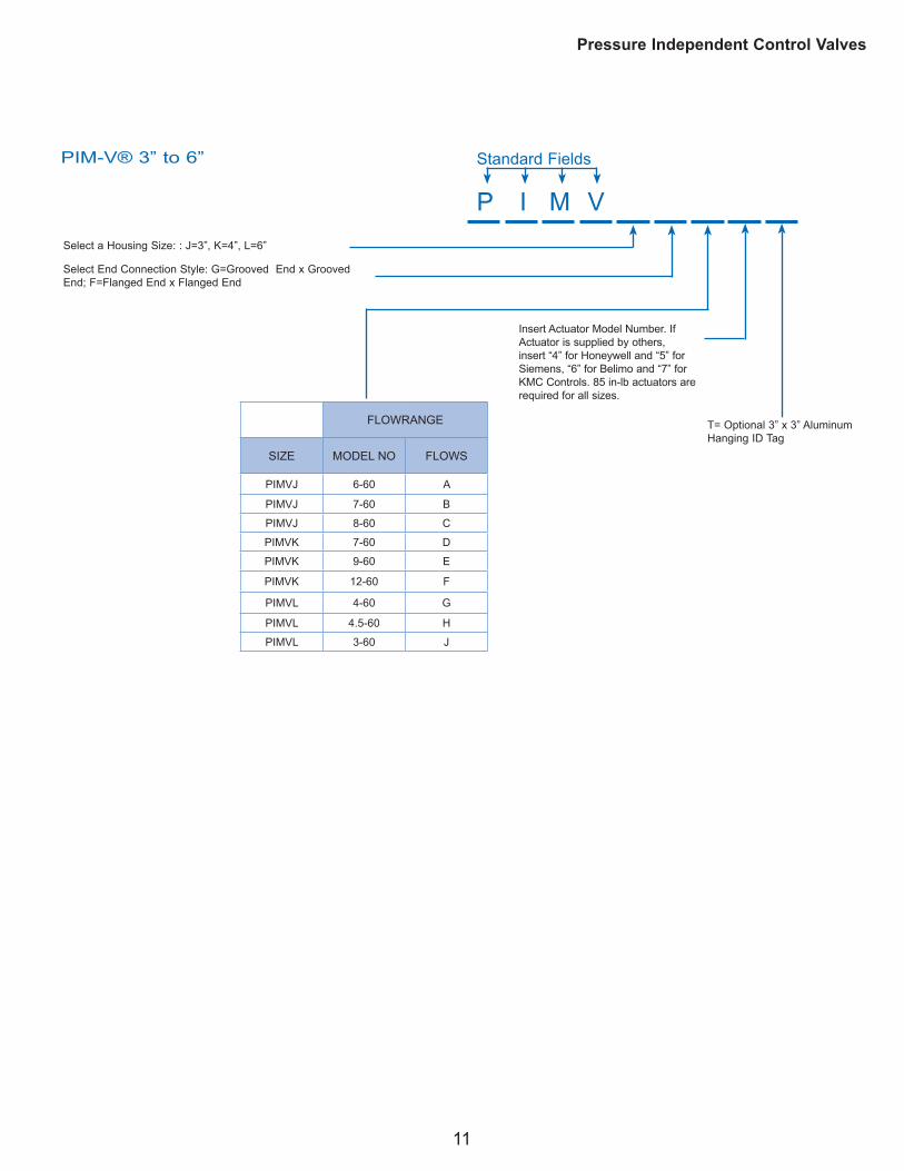
PIM-V® 3” to 6”
Select a Housing Size: : J=3”, K=4”, L=6”
Select End Connection Style: G=Grooved End x Grooved End; F=Flanged End x Flanged End
I M V
Standard Fields
FLOWRANGE
SIZE MODEL NO FLOWS
PIMVJ 6-60 A
PIMVJ 7-60 B
PIMVJ 8-60 C
PIMVK 7-60 D
PIMVK 9-60 E
PIMVK 12-60 F
PIMVL 4-60 G
PIMVL 4.5-60 H
PIMVL 3-60 J
Insert Actuator Model Number. If Actuator is supplied by others, insert “4” for Honeywell and “5” for Siemens, “6” for Belimo and “7” for KMC Controls. 85 in-lb actuators are required for all sizes.
T= Optional 3” x 3” Aluminum Hanging ID Tag

Standard 2–way IRIS Package with Unimizer®
Custom 3–way 3UF Package with Unimizer®
Custom 2–way 3WR Package with Unimizer®
· Isolator S with 20–Mesh Strainer, PT, and Drain Valve
· Union with Air Vent· 2–Way Unimizer
(with any standard actuator)· Isolator R with Automatic Flow
Control Cartridge and two PT valves
· Y–Strainer with Butterfly and Drain Valve
· Tee Connection· 3–Way Unimizer· Flanged Valve with
Butterfly Valve· Accessory Flanges with PTs
· Y–Strainer with Butterfly Valve· Tee Connection· Butterfly Valve on Bypass· 3–Way Unimizer· Wafer Valve with Butterfly Valve· Accessory Flanges with PTs
Griswold Controls’ Coil Piping Package program includes over 900 standard packages. Engineers do not have to design or detail the various elements that are required at the supply and return end of each coil. They can just select one of Griswold Controls standard packages, which are available
We also offer downsized components to the automatic temperature control as a standard package. Standard packages up to 2” ship within 48 hours after the order is received direct to the job site, preassembled and ready to install. If variations to the standard packages are necessary they can be readily accommodated, but they will affect the 48 hour ship time.
In addition, options such as hoses and extension kits can be easily added, but similarly this will increase the lead time.
Standard packages offer:
•
•
• Timely delivery
• Variety of options available: downsized automatic temperature control, extra pressure / temperature ports, and the inclusion of Griswold Controls Automizer® and Unimizer® temperature control valves.
Air Handling Units 2” to 3”Terminal Units 1/2” to 2” Equipment Rooms 4” to 8”
Custom Coil Piping PackagesGriswold Controls offers custom packages in line sizes from 2–1/2” thru 8”. The components can be shipped loose or assembled and shipped on a skid—your choice. These
connections and can include balancing valves, strainers,
of options are also available for customized packages, including the addition of hoses and extension kits.
• Isolator S with 20–mesh strainer, PT and drain valve
• Union with air vent• 2–Way Unimizer (with any
standard actuator)•
control cartridge and two PT valves
• drain valve
• Tee connection• 3–Way Unimizer•
valve• Accessory Flanges with PTs
• • Tee connection• • 3–Way Unimizer• •
Griswold Controls Representative
02/17F–5363D
48 Hour Standard Coil Piping Packages
Standard and Custom Coil Piping Packages
2803 Barranca Parkway • Irvine CA 92606 | Phone 800 838 0858 • Fax 800 543 8662
E-mail [email protected] | www.griswoldcontrols.com


