Download - Pioneer Sx 45 Service Manual

3s=r--*-**, t'r
t
*':*
o-si' €I -iiJ\! l :E*.{F
(0rrroruEen

AM /FN STEREO RECEIUER
s 450 HG
RF AssT AwE
lu,Quz2SA?25 xz ozor
(=l E
o-LN
T
.Y1C!
aJ
(o
5c.lcw
6
0,o3 2SC+61
zo{ 2scl222xz
l0v5d
eo
6(o
F9(-)
o
, 2, ( q
d-
SW ITCHIS ;SI SPEAKER S
1 POWE R OFF2 S P A3 SP OFF
{.ql
< ! ,
@
r
I K
a- E
&
2SCt 222
Ss MODESTEREO +---_ l'10N0
So LOUDNESS

63
RF Asst AwE
o,orHAlll3?
Cr1.0.4'/:S
STEREO INOEV 50 mA
o
e 6 l
C-)
:2
E.
o .
o l
dl--' .I J - Pi . i T ;
H.;i 'T=HCw\.41hs
n:<osC W .
t .e t
tar i-�
I
-'lI
2SCl222 xz I-t=fr 33.611
:<oo
3I
o
G>
Io ,
d
F+o -= - F" 5
;qF* I
I
l n r a - -
' r t l u s' d
F6-
3l9,N(-)F
G.
)< ,LO
e
an4H t
q3or2503l3R
+d
@
e
VRl BALANCECONTROL
1tl(85)
C2a6 C.O I
v)C ) o
5 ttr-3-
?sct3 8+Qrot
DxI
0 1
h A --25.
Uxos - ugot
DtAu tt ' t0tCAT0R8V 300mA x3
DS- l50Ax+

(DrrtoNEER"
0
,PLS
ASs'y AWK - 009
eu,,Qzor 2s c I gt gn" itAtiba',
13R x+
.--r* t s'hF
@@eo
ft4s)o(r/2w,_|.a |
@O @@
CJ
nJ
I
o
E
o l
q J t
E
-o9
6I
o
&.,
IE
= ADilusrHEN-rc?or22P +
(1/2w)
oros,ezoe 25 C l tltl 5At-4;
oo
lr
PE>
o ,-+'
9 .d
Cmz. Crroa-a+ ^+a
= ADJUSTI'IENTL2 14H
Rzoo l0 (llZWl{,4s 21t++
)cD
> 9
t
r"5. T
=:s59
2SCl3 8/|. Dror,ft12 tO! 2 xzQror Rlor 33 93_or FU
ocor250313R
n n t r r . v l n
UXos - UIOB U3o8
DIAL INDICATOREV 300mA x3
3c\rO
.<r-
U)C ) o
5 c r -c-!-

ASs'y AWK - 069
Qo,r,Qos 2SCl3tSAxz 2g\ltQlxz
,0.6V SW 3H a1
Rll E2K
.--* t S' hF
c@ eo
R.,'o('-uig I to @@
=.sa
= ADJUSTilENTc?os22P +
c-
E.
$oo
E
.J
:<o9-o
I
o
E>
O .-+ '
o ,
d
Crn 22P d-= ADilUSTtlENT
L2 11H
Rzco l0 (llZWlshs'1i++
Sfvcn (r
> 9
tr < o
r.5. T
zSCl3 8+ Dor,D312 lOE 2 xeQror Broijf 9qo' _FU:
tr)c-)-
c!
sO
q3o,250313R
Od
L)
h A . i v .v t n
Ujos ! U30t U3o6
DIAL INDICATOR8V 300mA x3
3c{
O
.f
v>C) (r
5 tc-!-

RF Ass'/ AWE
o, HA1.l37
REC- i
L i
I VI : SIONAL VOLTAGE ATG mA : DC CURRENT AT NO
V : DC VOLTAGE AT NO
63
oo
t,
€o
(ji
L\V
STEREO IND8V 50 mA
a',e HAllo
E
aoos
)<o9
c-cir
&-
l-.I I "i . iT ;
H'*i 'T=H
Y c -- Attr C3
Qns
2SCl222 xz I-l-r33.511
)<oo
ll
o
&>
=9 ,
9 .t
<f,"
o.o<.,c:,
I
I
tAsJ
2I
E
o3o,250313R
<:
N .
@
E
flK NK
I u^'Edh+HtEl'10Nlr0R I ffi 1M(85)
t-249 J.U I
Rzia iOoir
v)< ? @
5 t -tr-3-
EAKER OUTPUT 10.9V /EQ ( lKHr)
I G N A L
Dto,l
l { lstdt'b
3
?scl3 8+Qrot
2sv D 6
Drs - Dror
N-l50Ax+
DIAL INDICATOR8V 300nrA x3

RF Ass'7 AWE
oro2 2SC535
VCrlCr C,n4
P1'-Jlc-'-#lF ll;ia
LA vc, rct
la,Qnz2SA?25 xz ozo3,
T
.Y{'(v
EJ
r02
a -
l o
l d5a,
l j
l =J -
h
)<o9
a.
or-HAl.!3?
0,03 2SC+61
AP
sa
C63100/16'=l Rr+s24K
-oLr)
f,
l0v6drUa
6(o
5o
d
o
Oo
(J
SW ITCHES ;SI SPEAKER S
1 POWER OFF2 S P A3 SP OFF
I K
a-o
2SCt 222
Ss MooESTEREO ++ l '10N0
Ss LOUDNESS
5 2 F M M U T I N G0N -'t OFF
53 FUNCT|0NI At12 Ft13 PHONO+ AUX
Sa TA Pt MON tTO R-Q.EL- oN
S4 Ac VOLTAGE SELECTOR220V 4_ 240v
RESISTORS:lN OHM , 1 /4W, t \o /o TOLERANCE UNOTHERWISE NOTED K=K .C I , M=MC}
CAPACITORS :lN,4F UNLESS 0THERW ISE NOTED P= pF
I' VI : STGNAL VOLTAGE AT'-> mA : DC CURRENT AT N0
V : DC VOLTAGE AT NO
(
do
@S:

? 9 . ADJUSTMENT9.1 AM SECTION1. Through a 1k ohm resistor, connect an AM
signal generator to the AM antenna terminal.Set for 40OHz at 100dB and 3O% modulation.
2 Connect AC voltmeter to TAPE REC iack(L or R) .Set FUNCTION switch to AM position.Set AM signal generator and SX-450 dial in-dication to point A (600kHz).Adjust T6 for maximum indication on ACvoltmeter.Set AM signal generator and SX-450 dial in-dicat ion to point C (1,400kH2).
4 .
sx-450
7. Adjust TC4 for maximum indication on ACvoltmeter.
8. Again set AM signal generator and SX-450 dialindication to point A.
9. Adjust bar antenna core for maximum in-dication on AC voltmeter.
10. Return AM signal generator and SX-450 dialindication to point C.
11. Adjust TC5 for maximum indication on ACvoltmeter.
12. Repeat steps 4-11 to eliminate variations inAC voltmeter indications at noint A and C.
F
q '
.{
)
5 .
c).
1
AC vo l tmeter
AM s igna l genera tor
t r @
q
2 5

9.2 FM SECTION1. Through 300 ohm dummy antenna, connect
FM signal generator to the 300 ohm FMantenna terminals and set for 4OOHz at 100dBand IO0% modulation.
2. Connect AC voltmeter and distortion meter toTAPE REC jack (L or R).
3. Set FUNCTION switch to FM and MUTINGswitch to OFF.
4. Set FM signal generator and SX-450 dialindication to point A (90MHz).
5. Adjust T3 for maximum indication on ACvoltmeter.
6. Adjust T5 lower core for center of scaleindication on AM/FM meter.
7. Set FM signal generator for 9dB output andadjust T1 and T2 for maximum indication onAC voltmeter.
8. Set FM signal generator and SX-450 dialindicat ion to point C (106MHz).
9. Adjust TC3, then TC1 and TC2 for *u"i*rr- A | /
indication on AC voltmeter.10. Again set FM signal generator and SX-450 dial
indication to point A.11. Adjust T3, then T1 and T2 for maximum
indication on AC voltmeter.12. Repeat steps 8-11 to eliminate variations in
sensitivity at points A and C.13. Adjust "t4 for maximum sensitivity.14. Detune to noise only and adjust T5 lower core
for center of scale indication on FM meter.15. Set SX-450 dial indication to point B (98MHz)
and adjust FM signal generator for center ofscale indication on AM/FM meter.
16. Set FM signal generator output to 60dB andadjust T5 upper core for minimum distortion.
17. Repeat steps 14-16 eliminate variation in mini- J" 'a
mum distortion position. tl
A C v o l t m e t e r D i s t o r t i o n
0*-
f '{
T2
T1
TC1
l\\ t
FIa)
FM s igna l genera tor
t r @

9.3 MPX SECTION1. Through 300 ohm dummy antenna, connect
FM signal generator to 300 ohm FM antennaterminals.
2. Connect multiplex signal generator to extemalmodulation terminals of FM signal generator.
3. Connect oscilloscope horizontal input to MPXsignal pilot output and vertical input via probeto TP (No. 13) of circuit board.
sx-450
4. Set SX-450 dial indication to 98MHz and adjustFM signal generator for center of scale indi-cation on AM/FM meter.
5. With FM signal generator unmodulated, adjustVR1 so that lissajous pattern on oscilloscopebecomes stationary as shown in Fig. 12.
6. With MPX signal generator modulation lkHz,L + R 67.5kHz deviation and pilot 7.5kHzdeviation, adjust T4 for minimum distortion.
tl'
'at
IIr | }l 'I
III
III
IIi
AC vo l tmeter D is to r t ion meter
FM s igna l genera tor
D u m m y l o a d
Osc i l loscope
MPX signal generator
F ig .12
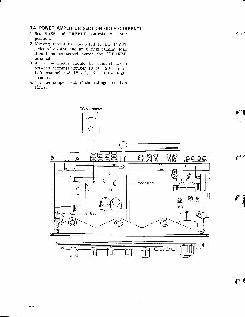
9 . 4 P O W E R A M P L I F I E R S E C T I O N ( I D L E C U R R E N T }1. Set BASS and TREBLE controls ro center a r' '
position.2. Nothing should be connected to the INPUT
jacks of SX-450 and an 8 ohm dummy loadshould be connected across the SPEAKERterminal.
3. A DC voltmeter should be connect acrossbetween terminal number 19 1+;, 20 (-) forLeft channel and 18 1+1, l7 (-) for Rightchannel.
4. Cut the jumper lead, if the voltage less than15mV.
f i
j**'
i t a
{
fNt #
DC Vo l tmeter
e d

)10 . D rAL CORD STRTNGTNGRemove the Front panel (See page 14, 15).1. Turn tuning drum fully clockwise (as viewed
from X direction in Fig. 13).2. Tie one end of cord to stud on inner section of
tuning drum (more easily performed by loosen-ing setscrew and temporarily removing tuningdrum from shaft).
3. Pass cord through pulley opening, make a halftum around the pulley, then route in thesequence: pulley A-Dial needle-pulley B-C.
4. Wind cord clockwise (as viewed from rear panel)3 turns around dial shaft, then route to pulley D.
5. Wind 3 tums around dial pulley and tie to springso that the cord is under tention.
1 6. Turn TUNING knob and confirm normal cord-motion. then trim off excess cord.
I
t 7. With tuning capacitorblades fully closed, move' dial needle to starting point (left edge of scale).
8. Apply laquor to tied ends of cord.
Spr ing hook
T ie to spr ing hook
sx-450
D I A L N E E D L E I N S T A L L A T I O N C A U T I O NMetal portion of dial pointer is plated.If this section is touched directly by hand orfingerprints and other impurities, it is difficult toremove dirt from aventurine finish. As this is notdesirable in terms of both appearance and anti-corrosion, take exteme care not to touch themetal section when handling the dial needle.
Dia l need le
. . ' \ - ' ' r l, . ' l
II
P u l l e y C
E n d :
StudStart: Fasten on end of the cord to start F i s . 1 3
P u l l e y D
T u n i n g d r u m
Dia l sha f t
2 9


