
National Grid
Planning and Advance Reservation of Capacity Agreement (PARCA)
SCHEDULE ONE
Technical Options Report
For
South Hook Gas Company Ltd (the Reservation Party)
Prepared by National Grid Gas (NGG)
14 December 2018
Issue 1, Version 1 0
National Grid
National Grid House
Warwick Technology Park
Gallows Hill
Warwick
CV34 6DA

National Grid
Table of Contents
EXECUTIVE SUMMARY .................................................................................................... 3
1 INTRODUCTION .......................................................................................................... 4
2 BACKGROUND ............................................................................................................ 5
3 TECHNICAL TERMS OF REFERENCE ....................................................................... 7
4 INVESTMENT THEMES .............................................................................................. 9
5 TECHNICAL OPTIONS FOR REINFORCEMENT ...................................................... 13
6 CONCLUSION ........................................................................................................... 22
7 Glossary ..................................................................................................................... 24
National Grid Confidential
3
EXECUTIVE SUMMARY
National Grid plc (“National Grid”) has received a Planning and Advance Reservation of
Capacity (PARCA) application from The South Hook Gas Company Ltd (“South Hook”) for
additional Entry Capacity at South Hook LNG Terminal.
The PARCA application requested Firm NTS Entry Capacity 1 , as Quarterly System Entry
Capacity (‘QSEC’), of up to 163,000,000kWh/d above the prevailing Obligated Entry Capacity2
at Milford Haven Aggregated System Entry Point (ASEP) by January 2023. This Entry Capacity
would be met at the South Hook LNG terminal at the western end of Feeder 28.
In the accompanying document, the Needs Case Report, there is an assessment of the impact
on National Transmission System (NTS) operations of releasing this additional capacity.
Analysis carried out has shown that the NTS will not have sufficient capability to
accommodate the requested additional capacity at South Hook terminal in 2023 and beyond,
based on the current physical network.
The purpose of this Technical Options Report (TOR) is to investigate the range of possible
physical changes to the NTS (“Reinforcements”), which could enable National Grid to release
the requested additional capacity. These reinforcements are grouped into the “Technical
Options”, which could be carried forward into Phase 2 of the PARCA for more detailed study.
The TOR documents the network modelling and other analysis work carried out by National
Grid to determine the additional network capability that would be provided by each of the
potential changes and the timescales for their implementation.
A range of possible network reinforcements has been assessed to determine technically
viable options for providing the requested capacity. This modelling shows that to increase
NTS entry capability from its present state, significant stretches of new pipeline may be
required, thereby potentially triggering the Development Consent Order (DCO) planning
process. It is estimated that it will take around seven years to achieve planning consent and
completion of design, installation and commissioning work for the new pipework. The
timeline for this work is indicative and may be revised through phase 2 of the PARCA process.
National Grid is continuing to explore Technical Options which may allow earlier release of
capacity.
1 Uniform Network Code, Transportation Principal Document, Section B2.1.7 2 Special Condition 1A. Definitions
National Grid Confidential
4
1 INTRODUCTION
The Technical Options Report is part of the procedures adopted by National Grid for major
national infrastructure projects that may require an application to the Planning Inspectorate3
for a Development Consent Order (DCO).
National Grid plc (“National Grid”) has received an application from South Hook Gas Company
Ltd (“South Hook”) for incremental NTS Entry Capacity at South Hook LNG terminal.
South Hook have requested 163,000,000kWh/day of NTS Entry Capacity above the prevailing
baseline obligation at Milford Haven Aggregated System Entry Point (ASEP).
This Technical Options Report provides:
• An overview assessment of the capability and capacity of the Transmission System
that is available to meet the changes to customer requirements
• The main conclusions from National Grid’s analysis work on the investment options
available.
Further information of relevance to consideration of the technical options is contained in the
appendices of the accompanying Needs Case Report. These appendices provide:
• A summary of National Grid’s legal obligations of relevance to this document
• An overview of transmission system policies standards and guidelines, analysis
principles including details of compliance requirements, key assessment criteria,
factors that limit transmission system capability, possible consequences of exceeding
capability limits and references to generic options for enhancing transmission system
capability are included in the Transmission Planning Code which can be found on the
National Grid website at https://www.nationalgridgas.com/charging
3 Further information is available from the National Infrastructure Planning website at
http://infrastructure.planningportal.gov.uk/.

National Grid Confidential
5
2 BACKGROUND
2.1 Transmission System Development
National Grid has a statutory duty to develop and maintain an efficient, coordinated and
economical system of gas supply under Section 9 of the Gas Act4. These duties, which are
documented in more detail in Standard Licence Conditions7, are included as part of the
summary of legal obligations referenced in Appendix C of the accompanying Needs Case
report.
Section 31 of the Planning Act 2008 (“the Planning Act”) requires a Development Consent
Order for a development that is or forms part of a Nationally Significant Infrastructure Project
(NSIP) and under Section 14(f) of the Planning Act “the construction of a pipe-line by a gas
transporter” is an NSIP if each of the conditions in subsections (2) to (5) of Section 20 of the
Planning Act is expected to be met.
Section 20 of the Planning Act 2008 states that:
“1) The construction of a pipe-line by a gas transporter is within section 14(1)(f) only if (when
constructed) each of the conditions in subsections (2) to (5) is expected to be met in relation
to the pipe-line.
2) The pipe-line must be wholly or partly in England.
3) Either—
a) the pipe-line must be more than 800 millimetres in diameter and more than 40
kilometres in length, or
b) the construction of the pipe-line must be likely to have a significant effect on the
environment.
4) The pipe-line must have a design operating pressure of more than 7 bar gauge.
5) The pipe-line must convey gas for supply (directly or indirectly) to at least 50,000
customers, or potential customers, of one or more gas suppliers.
4 Gas Act 1986: http://www.legislation.gov.uk/ukpga/1986/44/contents7 Standard conditions of the
gas transporter licence:
http://www.ofgem.gov.uk/Networks/GasDistr/otherwork/Documents1/8355Attachment_1_Standar
d_Conditions_for_GT_s.pdf

National Grid Confidential
6
6) In the case of a pipe-line that (when constructed) will be only partly in England, the
construction of the pipe-line is within section 14(1)(f) only to the extent that the pipe-line will
(when constructed) be in England.
7) “Gas supplier” has the same meaning as in Part 1 of the Gas Act 1986
c) 44) (see section 7A(11) of that Act).”
National Grid's Stakeholder, Community and Amenity Policy5 (“the Policy”) sets out how the
company will meet the duty to the environment placed upon it. These commitments include:
• only seeking to build new pipelines, compressor stations, pressure reduction
installations and other above ground gas installations where the existing
transmission infrastructure cannot be upgraded technically or economically to
meet transmission security standards;
• where new infrastructure is required seek to avoid areas nationally or
internationally designated for their landscape, wildlife or cultural significance,
and
• minimising the effects of new infrastructure on other sites valued for their
amenity.
The Policy also refers to the application of best practice methods to assess the environmental
impacts of proposals and identify appropriate mitigation and/or offsetting measures. The
Policy also promotes effective consultation with stakeholders and the public.
2.2 Assessment of Transmission System Capability
Transmission system capability is determined by the rating of plant and equipment, how
individual items are connected to form parts of the transmission system and the technical
characteristics of customer equipment connected to that part of the transmission system.
Appendix C of the accompanying Needs Case report provides more detailed information
about Transmission System performance requirements, the Institution of Gas Engineers and
Managers (IGEM) industry standard compliance requirements and generic options for
enhancing transmission system capability.
5 National Grid’s Stakeholder, Community and Amenity Policy:
http://www.nationalgrid.com/uk/LandandDevelopment/SC/Responsibilities/sched9/sche dule+9.htm

National Grid Confidential
7
3 TECHNICAL TERMS OF REFERENCE
The report has been undertaken based on an increase of NTS Entry Capacity of 163,000,000
kWh/d above the prevailing baseline obligation at Milford Haven ASEP, which represents the
supply quoted in the PARCA application.
The following areas have not been considered in this report:
• Cost and Construction issues: This report is not intended to cover any cost and
construction issues.
• System Outage: The possible construction programmes for the connection will
be subject to the availability of the appropriate outages for the works required.
System outages associated with the delivery of works associated with the
project were not considered in this study and will be identified as the Scheme
progresses.
3.1 Network Modelling Assumptions
Network modelling has been carried out to determine the benefit and feasibility of
reinforcement options and follows on from the modelling work documented in the Needs
Case report. The Needs Case and technical options modelling are based on the same physical
network topology and supply and demand scenarios. For ease of reference the three demand
scenarios are provided in Table 1 below.
Table 1: Details of the demand levels used for analysis
National Demand (mscm/d) South Wales Demand (mscm/d)
360 22.7
259 16.9
164 6.6
Further details of assumptions underpinning the network modelling can be found in Sections
4.1 to 4.3 of the Needs Case report. The starting point for the modelling of reinforcement
options was to model, for each demand level in Table 1, the level of supply from the Milford
Haven ASEP at which the existing network would become constrained (see section 4.4 of the
needs Case document). Further increases in supply, up to the level requested in the PARCA
application, were then simulated, and the various physical reinforcements were added to the

National Grid Confidential
8
topology in turn, to investigate their benefit in reducing or removing the various constraints
which may emerge.
3.2 Physical Investment Options Considered
The following types of options were considered when an investment was determined to be
required (the specific options will be detailed in the next Chapter):
3.2.1 Pipeline Uprating
Pipeline uprating involves increasing the maximum permitted operating pressure of a pipeline
so that the capacity of the pipeline is increased. The ability to use this option depends on a
number of factors including, but not limited to, the original design parameters and age and
condition of the existing pipeline. Where this option is technically feasible it can be considered
as an alternative to a new pipeline.
3.2.2 New Pipe
A new pipeline can be connected between existing points on the network. The length of new
pipelines is estimated using a suitable mapping tool or by using existing pipeline lengths.
3.2.3 Compressor Flow Modifications
Modifications to plant at existing compression sites can be carried out to increase the
maximum flow that can be achieved through a site and therefore, increasing the compression
capacity of the station.
3.2.4 Multi-junction Modifications
A multi-junction is a site where several pipelines met and consists of a series of valves that
can control the gas flow between the feeders. By carrying out a multijunction modification,
the gas flow direction can be changed to provide additional capability.
3.2.5 New Compressor Unit
A new compressor unit can be built within an existing compression site as a replacement for
an existing unit or a new addition. A new compressor unit is required when additional
compression power is identified as an investment solution.
3.2.6 New Compression Station
A new compressor station can be used as an investment solution as an alternative or to
compliment a pipeline investment. The approximate site of a new compressor will be
determined by the network analysis.

National Grid Confidential
9
4 INVESTMENT THEMES
National Grid has considered all available means of modifying or reinforcing its physical
network to accommodate the requested additional capacity at Milford Haven ASEP. The
starting point was to take the broadest possible view of the network as it stands and all the
new and existing routes which could be used to potentially increase the capacity of the
network to move additional gas from the Milford Haven area towards central areas. At this
stage in the PARCA process the aim was to put all reasonable options on the same footing
before proceeding to more detailed analysis.
When considering the current layout of the NTS, together with the geography of England and
Wales, there are a number of existing and potential new routes which could act as effective
conduits for increasing the capability of the network to accept additional flows at Milford
Haven ASEP.
There are also a variety of different types of investments that could be used to obtain value
from these pathways (compression, pipeline, uprating etc.). To reflect this fact, these conduits
or route options have been defined as investment “Themes” for the purposes of this report
and are listed below.
4.1 Theme 1: Carry out modifications to Felindre compressor station
and units to support increased flows
The compressor units at Felindre are designed to support the existing combined entry flow
obligations at Milford Haven. To support additional flow would require modifications to the
compression capability and this would therefore apply to any Technical Option involving
flowing the total Milford Haven supply through Felindre compressor station
4.2 Theme 2: Reinforce existing pipeline routes East of Wormington
Compressor Station
The primary existing corridor from South Wales to the centre of the network is via the feeders
running through Wormington compressor and then north eastwards towards Churchover.
This route supports the bulk of current obligated flows, but would be constrained at higher
flows due to its relatively small diameter feeders compared to those to the west of
Wormington.
4.3 Theme 3: Reinforce existing pipeline routes South of Wormington
Compressor Station
Feeders running south of Wormington currently offer limited capability for supporting
onward flow from South Wales. Feeder diameter reduces as the feeders approach the south

National Grid Confidential
10
west of the network and this is a constraint to increased flows. However, should these
constraints be addressed, with some other network modifications, it could be a viable
strategy to use this route as a primary supply for the southwest and as a support for the south
east (by reducing or reversing the prevailing flow along the southern feeders).
4.4 Theme 4: Reinforce existing pipeline routes between Felindre and
Wormington
Although this section of the network has substantial flow capability, constraints are likely to
emerge at higher flows, due to losses in pressure associated with the large distances involved
and the spacing of compression along the route. The constraint is likely to be reduced by
duplication of the existing feeders and adding compression capability between Felindre and
Wormington.
4.5 Theme 5: Create new offshore pipeline routes across/along the
Severn Estuary to connect to the existing network in the Southwest.
This approach involves creating new routes within the network, rather than reinforcing
existing areas of constraint. The prevailing supply to the south and southwest is via Midlands
and is supported by compression in the Midlands and East Anglia. With additional flows from
South Wales routed directly to the southwest across the Severn, prevailing flows could be
reversed with Milford Haven gas effectively feeding the southeast along the southern feeders
and using modification of existing compression.
4.6 Theme 6: Create new pipeline routes to connect South Wales
directly to central areas of the NTS (bypassing all constraints in the
West Midlands)
Following the same principle to the previous theme, this approach aims to support the
additional flows through a new route directly to the centre of the network and to make use
of existing compression capability in the Midlands.
4.7 Theme 7: Create new pipeline routes from Wormington to connect
directly to central areas of the NTS (bypassing some constraints in
the West Midlands)
This strategy makes use of existing routes from Milford Haven to Wormington, but then
avoids the constraints in the West Midlands by making a connection directly into the demand
centres of the South East. It is anticipated that relatively modest loading of the new feeder
averts the need for extra compression.
National Grid Confidential
11
4.8 Theme 8: Uprate maximum operating pressures of pipeline,
compressor stations and AGIs in the region.
The uprating of assets to operate at a higher pressure, may allow significantly more supply
from Milford Haven onto the network. Although pressure losses along pipelines increase, if
the pressures upstream can safely rise above current limits, downstream pressures can be
maintained at a level that allows demand obligations to be met. Consideration has been given
to the maximum potential rating of each section of pipework in regions identified by the other
themes.
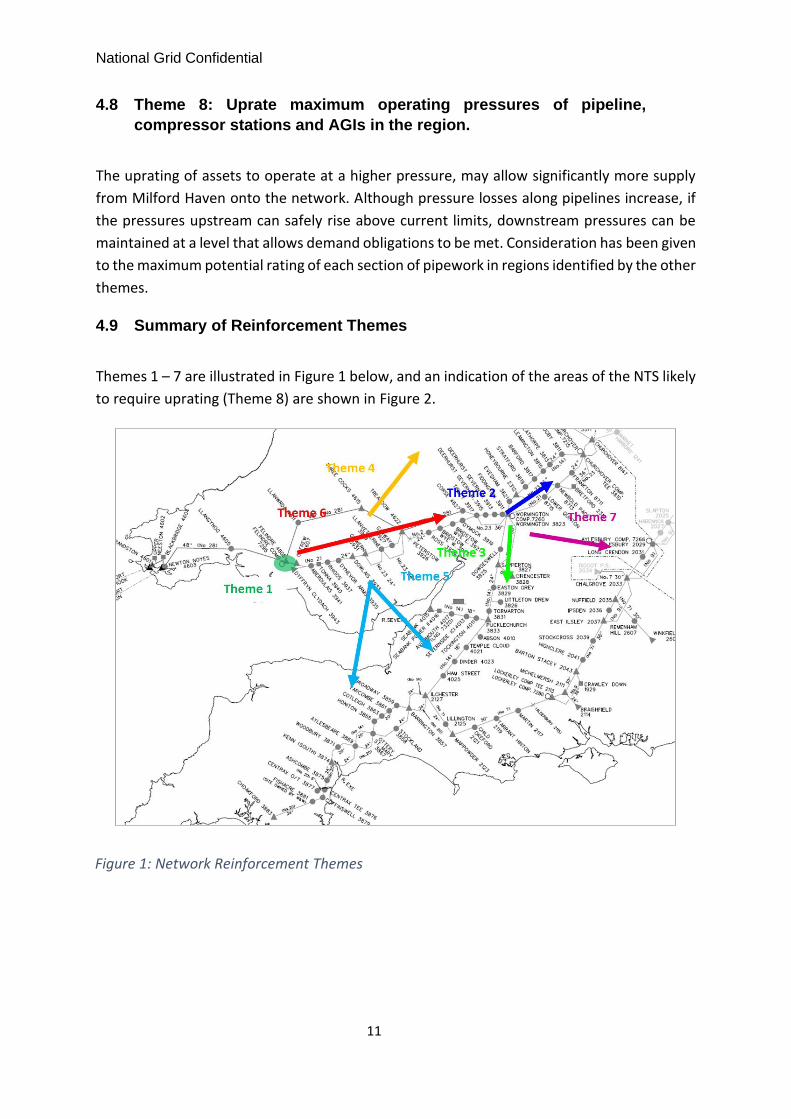
4.9 Summary of Reinforcement Themes
Themes 1 – 7 are illustrated in Figure 1 below, and an indication of the areas of the NTS likely
to require uprating (Theme 8) are shown in Figure 2.
Figure 1: Network Reinforcement Themes

National Grid Confidential
12
Figure 2: Potential Areas for Pressure Uprating (shown in yellow)
These Themes have been presented to our internal stakeholder group, consisting of
experts in the fields of compressor and pipeline design and development, network
investment and consents and planning. The report now moves on to consider how
these themes can be translated into combination of specific reinforcements to the
NTS.

National Grid Confidential
13
5 TECHNICAL OPTIONS FOR REINFORCEMENT
This section continues to explore the reinforcement themes introduced in the previous
section, by looking in more detail at how these might address the network constraints which
arise as increases in flow from Milford Haven are modelled on the current network. The aim
was to arrive at options based on one or more themes, that each include logical series of
investments to effectively address the constraints.
5.1 General Considerations
Maps for all the options described in Section 5 can be found in the accompanying document
(“South Hook PARCA_Phase 1_Maps v2 pdf”).
Technical and benefit filters have been applied to each of the Technical Options detailed in
this chapter and to the specific reinforcements of which they are comprised. The technical
filter provides an assessment of whether the reinforcements are viable from an engineering
point of view and the benefit filter considers whether there are any reinforcements and
Technical Options which would offer no comparative benefit. Relevant experts within
National Grid have been consulted in the process of applying these filters. None of the
Technical Options described in this chapter have been discounted through this process.
It has become clear during the network modelling work that, to increase capability to the
required level, a combination of specific investments would be required. No single individual
investment (e.g. new pipeline or compressor) is sufficient to achieve the requested increase
in capability alone. Furthermore, it has been shown that solutions based around a single
investment theme (e.g. Felindre to Wormington) would not be sufficient to provide the
necessary additional capability.
The Technical Options presented all correspond with the Investment Themes described in the
previous chapter, with all options encompassing a number of themes. Each Technical Option
is a group of individual network reinforcements that are required in order to provide the
increased network capability to allow release of the requested additional capacity at Milford
Haven.
Felindre Compressor Capability
All options involve modifications at Felindre Compressor station. The initial requirement
identified is a modification to the lead unit pipework to support higher flows, together with
the investments needed to achieve a corresponding increase in capability during backup
operation. It is currently assumed that the backup units would either be re-wheeled or
replaced in order to support both lower flow scenarios and the high flows required to support
the additional capacity requested in the PARCA application.

National Grid Confidential
14
For all of the following strategies it should be assumed that the increase in flow capability at
Felindre is included.
5.2 Option A: Reinforcements East and West of Wormington
The results of the modelling indicate that the following reinforcements comprise the most
effective option under this strategy:
5.2.1 Capability increase 1:
• Modifications at Wormington compressor to support increased flow capability
in backup operation.
• Duplication of the existing Wormington to Honeybourne pipeline (Feeder 14)
5.2.2 Capability increase 2:
• Duplication of the existing Tirley to Wormington pipeline, with modifications to
the AGI at Tirley to ensure differential pressure control.
5.2.3 Capability Increase 3:
• Modifications at Churchover compressor to support higher flows to the East.
• Duplication of pipework connecting Churchover compressor to Churchover
multijunction to support higher flows
5.2.4 Capability increase 4:
• A new compressor station around the site of Three Cocks AGI, providing lead
and backup capability
• Modifications to Felindre compression capability to support a further increase
in flows
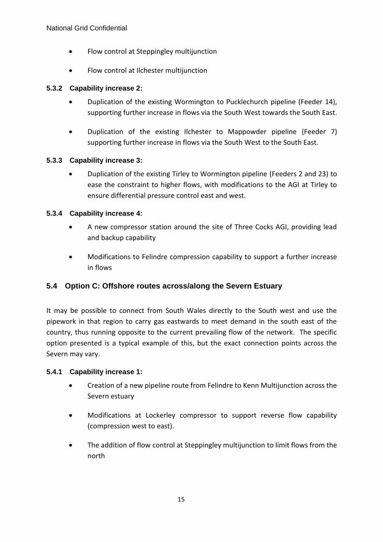
5.3 Option B: Reinforcements West and South of Wormington
The following reinforcements make up an effective option for making use of the feeder routes
to the south of Wormington.
5.3.1 Capability increase 1:
• Duplication of pipework from Pucklechurch to Ilchester to increase flow
capability to the south west
• Modifications at Lockerley compressor to support reverse flow capability
(compression west to east).
National Grid Confidential
15
• Flow control at Steppingley multijunction
• Flow control at Ilchester multijunction
5.3.2 Capability increase 2:
• Duplication of the existing Wormington to Pucklechurch pipeline (Feeder 14),
supporting further increase in flows via the South West towards the South East.
• Duplication of the existing Ilchester to Mappowder pipeline (Feeder 7)
supporting further increase in flows via the South West to the South East.
5.3.3 Capability increase 3:
• Duplication of the existing Tirley to Wormington pipeline (Feeders 2 and 23) to
ease the constraint to higher flows, with modifications to the AGI at Tirley to
ensure differential pressure control east and west.
5.3.4 Capability increase 4:
• A new compressor station around the site of Three Cocks AGI, providing lead
and backup capability
• Modifications to Felindre compression capability to support a further increase
in flows
5.4 Option C: Offshore routes across/along the Severn Estuary
It may be possible to connect from South Wales directly to the South west and use the
pipework in that region to carry gas eastwards to meet demand in the south east of the
country, thus running opposite to the current prevailing flow of the network. The specific
option presented is a typical example of this, but the exact connection points across the
Severn may vary.
5.4.1 Capability increase 1:
• Creation of a new pipeline route from Felindre to Kenn Multijunction across the
Severn estuary
• Modifications at Lockerley compressor to support reverse flow capability
(compression west to east).
• The addition of flow control at Steppingley multijunction to limit flows from the
north

National Grid Confidential
16
• The additional of flow control at Kenn multijunction to limit south west
extremity pressures
5.4.2 Capability increase 2:
• Modifications to Felindre compression capability to support a further increase
in flows
5.5 Options D1 and D2: Offshore routes across the Severn Estuary with
Reinforcement of Existing routes South of Wormington
Options based on this strategy involve a shorter Severn crossing than those based on strategy
C, but at the expense of requiring some duplication of existing pipework. The options
presented have been shown to provide a large amount of additional capability without the
need for new compression.
5.5.1 Capability increase 1:
• Duplication of pipework from Pucklechurch to Ilchester to increase flow
capability to the south west
• Modifications at Lockerley compressor to support reverse flow capability
(compression west to east).
• Additional of flow control at Steppingley multijunction
• Additional of flow control at Ilchester multijunction
5.5.2 Capability increase 2 (Option D1):
• Creation of a new pipeline route from Felindre to Pucklechurch across the
Severn estuary
• Duplication of the existing Ilchester to Mappowder pipeline supporting further
increase in flows via the South West to the East.
• Modifications to Felindre compression capability to support a further increase
in flows
5.5.3 Capability increase 2 (Option D2):
• Creation of a new pipeline route from Treaddow to Pucklechurch across the
Severn estuary
• Duplication of pipeline between Felindre and Three Cocks / Treaddow

National Grid Confidential
17
• Modifications to Felindre compression capability to support a further increase
in flows
5.6 Option E: New pipeline routes to connect South Wales directly to
central areas of the NTS (bypassing all constraints in the West
Midlands)
As with the previous strategy additional flows take a completely new route, which benefits
from being relatively unconstrained. For this reason, and because the new pipework connects
to an existing compressor station in a central area of the network, the option presented offers
substantial capability without new compression.
5.6.1 Capability increase 1:
• Creation of new pipework route from Three Cocks AGI to Alrewas Compressor
• Additional of flow control at Three Cocks to balance flows to Wormington /
Alrewas
5.6.2 Capability increase 2:
• Duplication of pipeline between Felindre and Three Cocks
• Modifications to Felindre compression capability to support a further increase
in flows
5.7 Option F: New pipeline routes from Wormington to connect directly
to central areas of the NTS (bypassing some constraints in the West
Midlands)
5.7.1 Capability increase 1:
• Creation of new pipework route from Wormington Compressor to Aylesbury
Compressor
• Addition of flow control north and south of Aylesbury to balance flows from
Wormington and Huntington.
5.7.2 Capability increase 2:
• Duplication of the existing Tirley to Wormington pipeline, with modifications to
the AGI at Tirley to ensure differential pressure control.
5.7.3 Capability increase 3:
• New Compressor around the site of Three Cocks AGI

National Grid Confidential
18
• Modifications to Felindre compression capability to support a further increase
in flows
5.8 Option G: Pipeline, AGI and Compressor Pressure Uprating
The uprating of the maximum operating pressures of National Grid’s pipelines and AGIs is a
strategy which may provide some additional capability when used in combination with new
pipe build reinforcements. Uprating is likely to require extensive work to the existing assets,
up to and including the need for pipe diversions. The viability and associated cost of the
strategy is dependent upon a number of factors, including the inherent design limitations of
existing assets and potential new environmental infringements. Until more detailed surveying
works have been carried out on the relevant assets, it is not possible to give a firm indication
of the viability of, or timeline for, uprating works.
Options for utilising the potential for uprating will be pursued in combination with new
pipeline and compression options as appropriate through phase 2 of the PARCA. Based on
initial modelling work, the likely progression of reinforcements is as follows:
5.8.1 Capability increase 1:
• Modifications at Wormington compressor to support increased flow capability
in backup operation.
• Duplication of pipework between Wormington and Honeybourne (feeder 14)
5.8.2 Capability increase 2:
• Pressure Uprating of Felindre compressor station and units
• Pressure uprating of Felindre to Treaddow pipeline route (feeder 28)
5.8.3 Capability increase 3:
• Modifications at Churchover compressor to support higher flows to the East.
• Duplication of pipework connecting Churchover compressor to Churchover
multijunction to support higher flows
5.8.4 Capability increase 4*:
• Pressure uprating at Milford Haven terminals (customer requirement to uprate)
• Pressure uprating of Milford Haven to Felindre pipeline route (Feeder 28)

National Grid Confidential
19
5.8.5 Capability increase5*:
• Duplication of the existing Tirley to Wormington pipeline, with modifications to
the AGI at Tirley to ensure differential pressure control.
*Note: Network modelling results indicate that similar capability increases can be achieved
by reversing the order of these reinforcements
5.9 Technical Options Summary
A summary of the individual reinforcements and how they make up each of the Technical
Options A to H is shown in Table 2. The reinforcements are grouped as per the Investment
Themes presented in Chapter 4.
Table 2: Matrix of Investment Themes and Technical Options
Theme No
Theme Description Technical Options
A B C D1 D2 E F G
1
Felindre Compressor Modifications
• Lead and Back up unit high flow Modifications
2
Existing routes along Feeder 14: East of Wormington
• Modifications at Wormington compressor
• Duplication of Wormington to Honeybourne Feeders
• Modifications at Churchover compressor station
• Duplication Churchover Compressor to Churchover Junction
3
Existing routes: South of Wormington
• Duplication of Pucklechurch to Ilchester
• Duplication of Wormington to Pucklechurch; duplication of Ilchester to Mappowder

National Grid Confidential
20
Theme No
Theme Description Technical Options
A B C D1 D2 E F G
• Flow control at Steppingley and Ilchester
• Lockerley compressor reverse flow
4
Existing routes between Felindre and Wormington
• Duplication of Tirley to Wormington
• Flow control Modifications to Tirley PRI.
• Duplication of Felindre to Three Cocks / Treaddow
• New compressor station near Three Cocks AGI ~30MW.
5
Offshore routes across/along the Severn Estuary
• New pipeline route from Felindre to Kenn or similar
• New pipeline route from Felindre to Pucklechurch
• New pipeline route from Treaddow to Pucklechurch
6
New pipeline routes to connect South Wales directly to central areas of the NTS (bypassing all constraints in the West Midlands)
• New pipework route from Three Cocks to Alrewas Compressor; flow control at Three Cocks.
• Flow control at Three Cocks
7
New pipeline routes from Wormington to connect directly to central areas of the NTS (bypassing some constraints in the West Midlands)
• New pipework route from Wormington Compressor to Aylesbury Compressor

National Grid Confidential
21
Theme No
Theme Description Technical Options
A B C D1 D2 E F G
• Flow control north and south of Aylesbury
8
Pipeline, AGI and Compressor Uprating
• Uprating of assets to higher operating pressure: Felindre to Treaddow
• Uprating of assets to higher operating pressure: Milford Haven to Felindre
5.10 Working assumptions on Investment Timescales
The specific reinforcements which make up the Technical Options fall into several
classifications and National Grid can estimate the duration of each type of investment. Whilst
National Grid will make all reasonable endeavours to complete planning, design and
installation of new assets as quickly as is safe and efficient, Table 3 below gives the indicative
timescales, based on the best information available.
Table 3: Estimated Timeline for Investments
Investment Type Estimated Duration of Work6
New Pipeline (new route or duplication of existing route) Up to 7 Years
New Compressor Station / compressor units Up to 7 Years
Compressor Flow Modifications 2 Years
Compressor Re-wheel Minimum 1 Year
AGI Modifications / Addition of Flow Control 3 Years
Pipeline Uprating Minimum 3 Years7
It can be seen from a review of the options presented in section 5.9 that all options would
require new pipeline build to achieve any initial increase in entry capability. Other types of
investment can be made in shorter timescales, but will not enhance existing capability
without accompanying pipeline build. Seven years is estimated as the timescale within which
National Grid could provide the necessary capability.
6 Further details and assumptions for typical timeline are provided in the Phase 1 report 7 May be significantly longer, depending on requirement for diversions and outages

National Grid Confidential
22
6 CONCLUSION
This report recommends that options A to G, as listed in Table 4, proceed to Phase 2 of the
PARCA process on the basis that they are both technically viable and expected to provide
sufficient network capability to allow release of the requested incremental capacity at Milford
Haven ASEP. The estimated timescale for release of capacity through the implementation of
these options is seven years.
The work underlying this report has involved extensive network modelling and expertise in
identifying and carrying out a high-level assessment of all the physical changes National Grid
could make to the NTS to accommodate the increase in capacity requested by South Hook.
This work will continue in Phase 2 of the PARCA and will be accompanied by more detailed
investigations such as route corridor studies, and further cost benefit analysis which will allow
us to narrow down and then select an option to take forward through the necessary planning
and design stages. Alongside those options which explicitly involve investment in new assets
(pipework, compressors, etc.), National Grid will carry out further studies into the potential
for uprating of the pressure capability of its assets where this is technically feasible and would
give significant increase in entry capability.

National Grid Confidential
23
Table 4: Summary of Technical Options
Op
tion
Cap
ability Ste
p
Increase
Option Elements
All Felindre Capability Mods
A 1 Duplication of Wormington to Honeybourne; Mods at Wormington compressor.
2 Duplication of Tirley to Wormington; Mods to Tirley PRI.
3 Mods at Churchover compressor station; duplication of Churchover compressor to Churchover junction
4 New compressor station near Three Cocks ~30MW. Modifications to Felindre compression capability to support a further increase in flows
B 1
Duplication of Pucklechurch to Ilchester; Mods at Lockerley compressor for reverse flow; flow control at Steppingley and Ilchester
2 Duplication of Wormington to Pucklechurch; duplication of Ilchester to Mappowder
3 Duplication of Tirley to Wormington; Mods at Tirley
4 New compressor station near Three Cocks ~30MW. Modifications to Felindre compression capability to support a further increase in flows
C 1
New pipeline route from Felindre to Kenn; Mods at Lockerley compressor for reverse flow; flow control at Steppingley and Kenn.
2 Modifications to Felindre compression capability to support a further increase in flows
D1 1
Duplication of Pucklechurch to Ilchester; mods at Lockerley compressor for reverse flow; flow control at Steppingley and Ilchester
2 New pipeline route from Felindre to Pucklechurch; duplication of Ilchester to Mappowder; Modifications to Felindre compression capability to support a further increase in flows
D2 1
Duplication of Pucklechurch to Ilchester; mods at Lockerley compressor for reverse flow; flow control at Steppingley and Ilchester
2 New pipeline route from Treaddow to Pucklechurch; duplication of Felindre to Three Cocks / Treaddow; duplication of Ilchester to Mappowder; Modifications to Felindre compression capability to support a further increase in flows
E 1
New pipeline route from Three Cocks to Alrewas Compressor; flow control at Three Cocks.
2 Duplication of Felindre to Three Cocks; Modifications to Felindre compression capability to support a further increase in flows
F 1
New pipework route from Wormington Compressor to Aylesbury Compressor; flow control north and south of Aylesbury.
2 Duplication of Tirley to Wormington; flow modifications at Tirley
3 New Compressor around the site of Three Cocks AGI; Modifications to Felindre compression capability to support a further increase in flows
G 1 Duplication of Wormington to Honeybourne; Mods at Wormington compressor.
2 Uprating of assets to higher operating pressure: Felindre to Treaddow
3
Mods at Churchover compressor station; duplication of Churchover compressor to Churchover junction

National Grid Confidential
24
4 Uprating of assets to higher operating pressure: Milford Haven to Treaddow
5 Duplication of Tirley to Wormington; Mods to Tirley PRI.
7 Glossary
ASEP (Aggregate System Entry Point) - A term used to refer to a gas supply terminal or group
of gas supply terminals for which NTS Entry Capacity is sold.
Compressor Station - An installation that uses gas turbine or electricity driven compressors
to boost pressures in the pipeline system. Used to increase transmission capacity and move
gas through the network.
Entry Capability – the entry capability of the system is the quantity of gas that can be inputted
into the NTS. Entry Capability can be considered on a site specific, regional or wider locational
basis and it may vary with respect to the distribution and volume of network supply and
demand.
Entry Capacity – the right to flow gas onto the NTS under the UNC.
Gas Transporter (GT) - Formerly Public Gas Transporter (PGT). GTs, such as National Grid, are
licensed by the Gas and Electricity Markets Authority to transport gas to consumers.
Investment – an investment to overcome a system constraint is the building of additional
infrastructure or modification of existing infrastructure such as a reinforcement pipeline or
modification of a compressor.
Kilowatt hour (kWh) - A unit of energy used by the gas industry. Approximately equal to
0.0341 therms. One Megawatt hour (MWh) equals 103 kWh, one Gigawatt hour (GWh) equals
106 kWh, and one Terawatt hour (TWh) equals 109 kWh.
Liquefied Natural Gas (LNG) - Gas stored and / or transported in liquid form.
National Transmission System (NTS) - A high-pressure system consisting of terminals,
compressor stations, pipeline systems and offtakes. Designed to operate at pressures up to
85 barg. NTS pipelines transport gas from terminals to NTS offtakes.
National Transmission System Offtake - An installation defining the boundary between NTS
and LTS or a very large consumer. The offtake installation includes equipment for metering,
pressure regulation, etc.
Therm - An imperial unit of energy. Largely replaced by the metric equivalent: the kilowatt
hour (kWh). 1 therm equals 29.3071 kWh.

National Grid Confidential
25
Transmission Planning Code - The Transmission Planning Code describes National Grid’s
approach to planning and developing the NTS in accordance with its duties as a gas
transporter and other statutory obligations relating to safety and environmental matters. The
document can be found at https://www.nationalgridgas.com/charging


