Download - Plant chemistry RO system

Plant Chemistry
Reveres Osmosis System
Prepared By : -
Umar Farooq Senior Chemist / Shift Supervisor
MSC ( Chemistry ) MBA ( Marketing )
SEC Shoaiba Makkah
Saudi Arabia
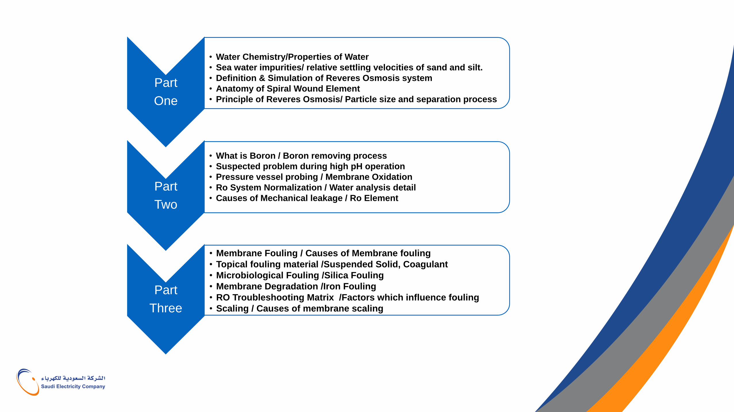
Part
One
• Water Chemistry/Properties of Water
• Sea water impurities/ relative settling velocities of sand and silt.
• Definition & Simulation of Reveres Osmosis system
• Anatomy of Spiral Wound Element
• Principle of Reveres Osmosis/ Particle size and separation process
Part
Two
• What is Boron / Boron removing process
• Suspected problem during high pH operation
• Pressure vessel probing / Membrane Oxidation
• Ro System Normalization / Water analysis detail
• Causes of Mechanical leakage / Ro Element
Part
Three
• Membrane Fouling / Causes of Membrane fouling
• Topical fouling material /Suspended Solid, Coagulant
• Microbiological Fouling /Silica Fouling
• Membrane Degradation /Iron Fouling
• RO Troubleshooting Matrix /Factors which influence fouling
• Scaling / Causes of membrane scaling
Why Water is Unique Water is only substance that exist in form of solid , liquid and steam Specific heat = 1calorie/gram It expand = 1600 time Three Isotopes = H2O , D2O , T2O Heat of fusion = 144Btu / Lbs. Heat of vaporization = 980 Btu / Lbs. Freezing Expand = 1/9 Depending upon pressure ,its boil with in the temperature = 35-704F*
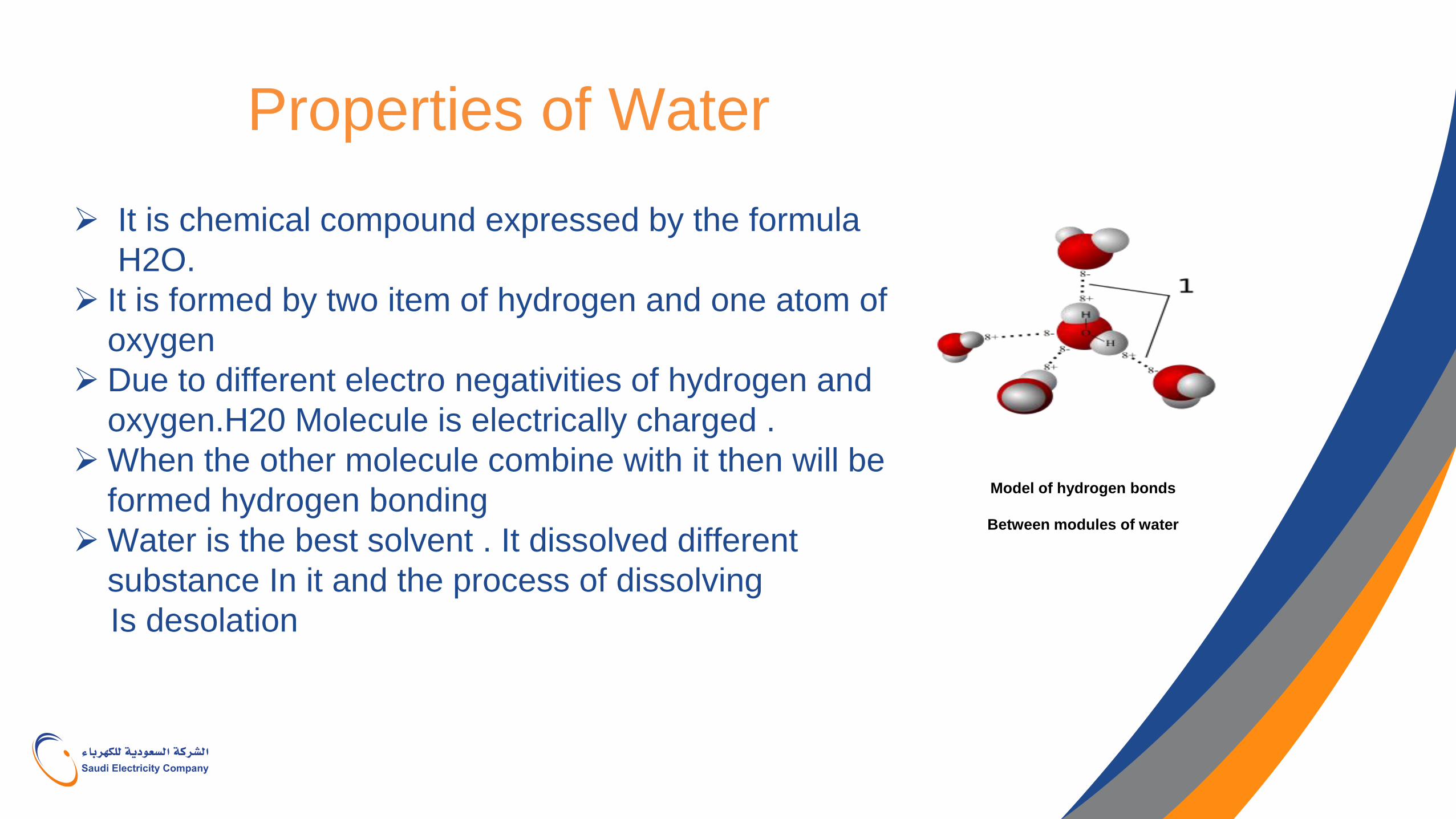
Properties of Water
It is chemical compound expressed by the formula
H2O.
It is formed by two item of hydrogen and one atom of
oxygen
Due to different electro negativities of hydrogen and
oxygen.H20 Molecule is electrically charged .
When the other molecule combine with it then will be
formed hydrogen bonding
Water is the best solvent . It dissolved different
substance In it and the process of dissolving
Is desolation
Model of hydrogen bonds
Between modules of water
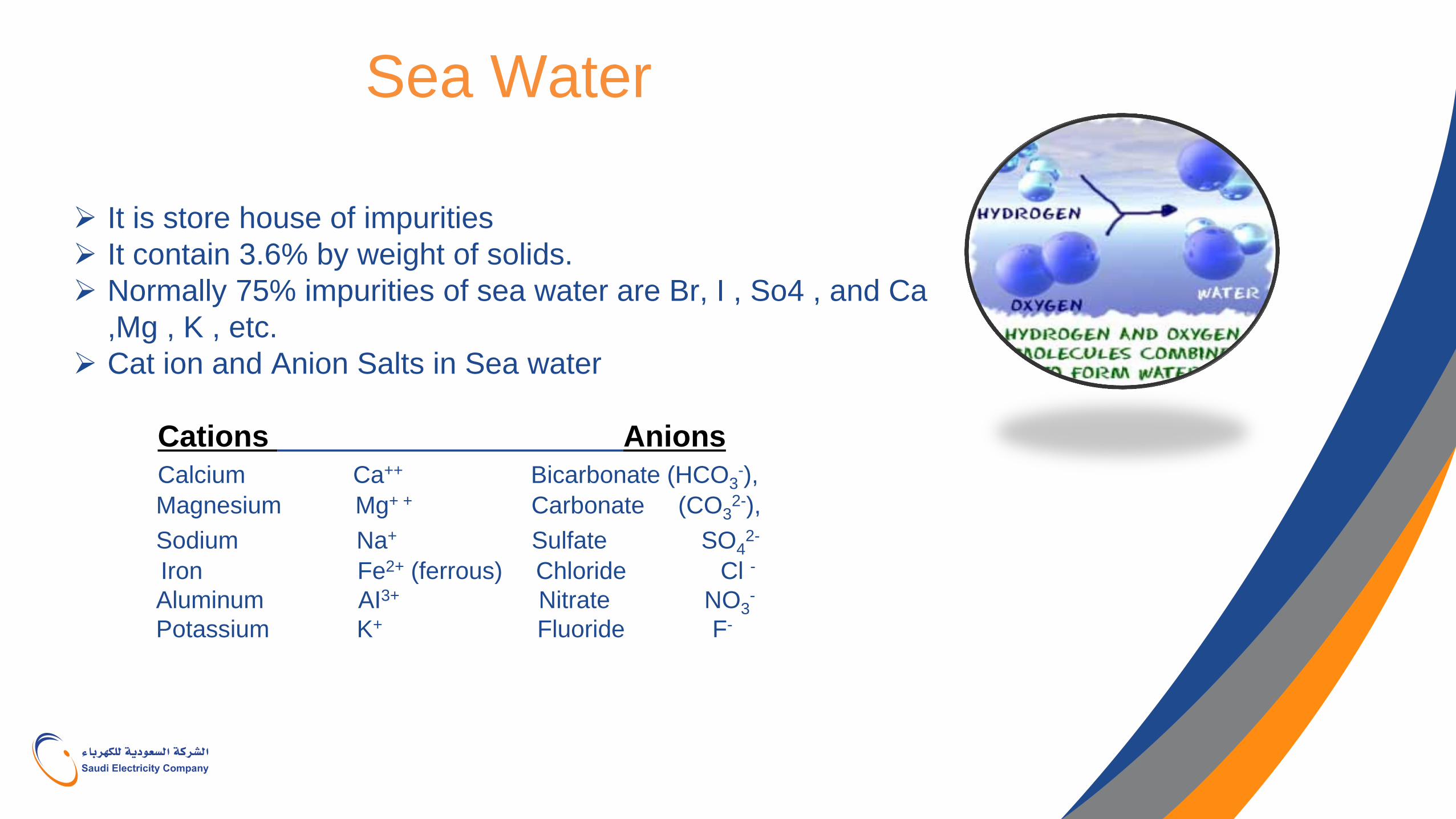
Sea Water
It is store house of impurities
It contain 3.6% by weight of solids.
Normally 75% impurities of sea water are Br, I , So4 , and Ca
,Mg , K , etc.
Cat ion and Anion Salts in Sea water
Cations Anions Calcium Ca++ Bicarbonate (HCO3
-),
Magnesium Mg+ + Carbonate (CO32-),
Sodium Na+ Sulfate SO42-
Iron Fe2+ (ferrous) Chloride Cl -
Aluminum AI3+ Nitrate NO3-
Potassium K+ Fluoride F-
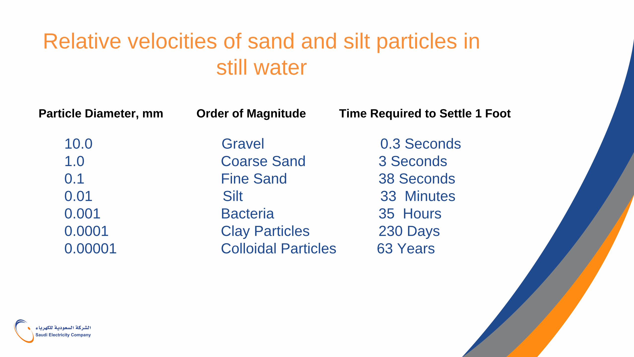
Relative velocities of sand and silt particles in
still water
Particle Diameter, mm Order of Magnitude Time Required to Settle 1 Foot
10.0 Gravel 0.3 Seconds
1.0 Coarse Sand 3 Seconds
0.1 Fine Sand 38 Seconds
0.01 Silt 33 Minutes
0.001 Bacteria 35 Hours
0.0001 Clay Particles 230 Days
0.00001 Colloidal Particles 63 Years
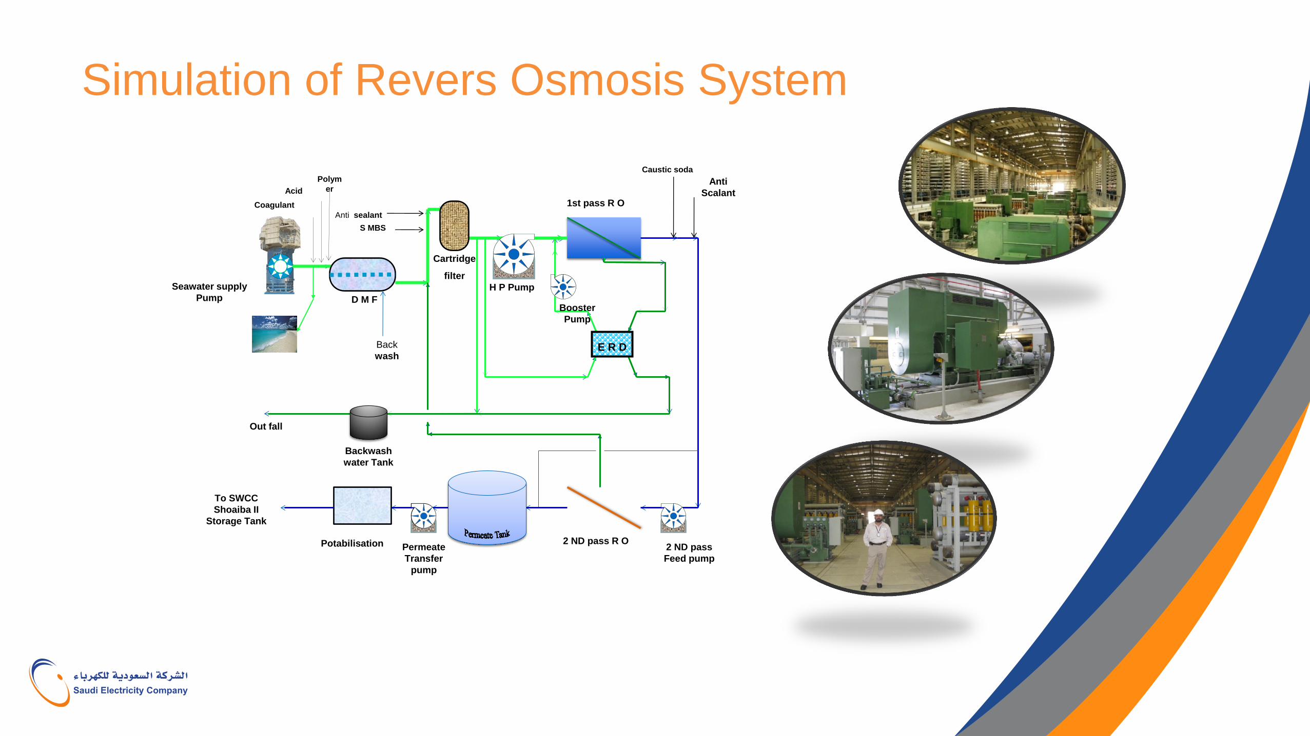
Simulation of Revers Osmosis System
Seawater supply
Pump D M F
Cartridge
filter
H P Pump
Booster
Pump
1st pass R O
E R D
2 ND pass R O 2 ND pass
Feed pump
Permeate
Transfer
pump
Potabilisation
Backwash
water Tank
Out fall
To SWCC
Shoaiba II
Storage Tank
S MBS
Anti sealant
Anti
Scalant
Caustic soda
Acid
Coagulant
Polym
er
Back
wash
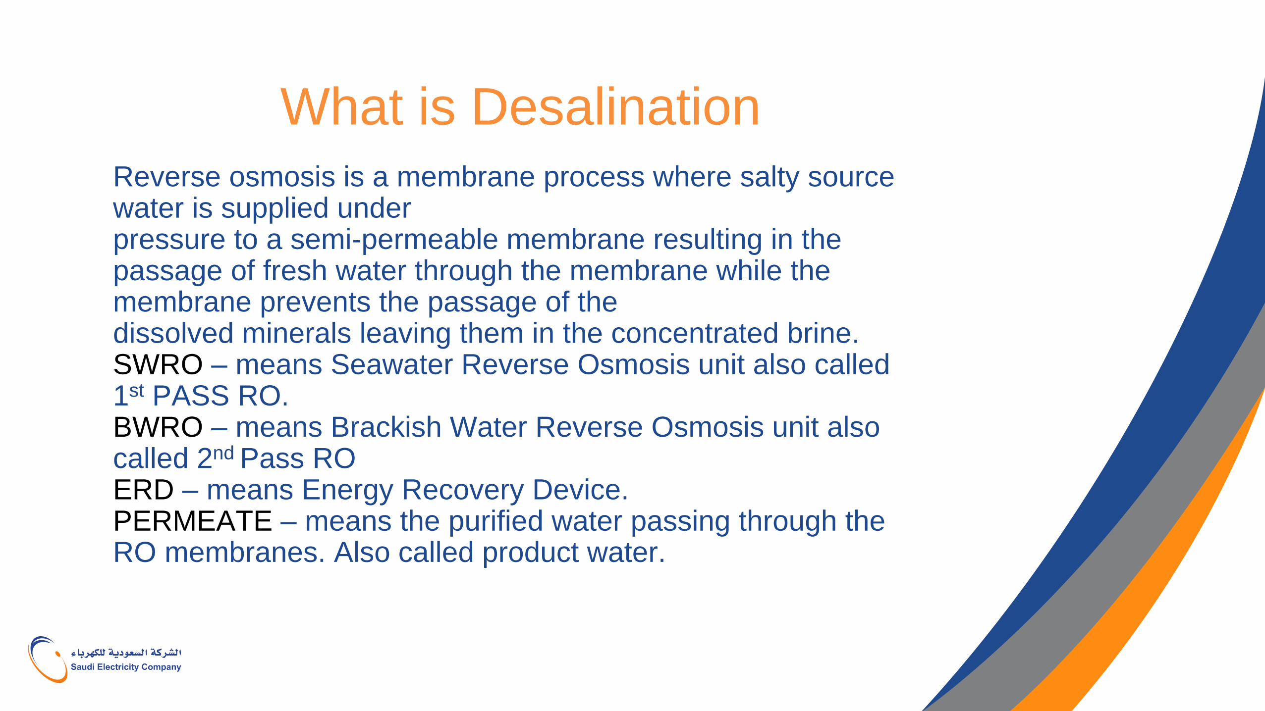
What is Desalination
Reverse osmosis is a membrane process where salty source water is supplied under pressure to a semi-permeable membrane resulting in the passage of fresh water through the membrane while the membrane prevents the passage of the dissolved minerals leaving them in the concentrated brine. SWRO – means Seawater Reverse Osmosis unit also called 1st PASS RO. BWRO – means Brackish Water Reverse Osmosis unit also called 2nd Pass RO ERD – means Energy Recovery Device. PERMEATE – means the purified water passing through the RO membranes. Also called product water.
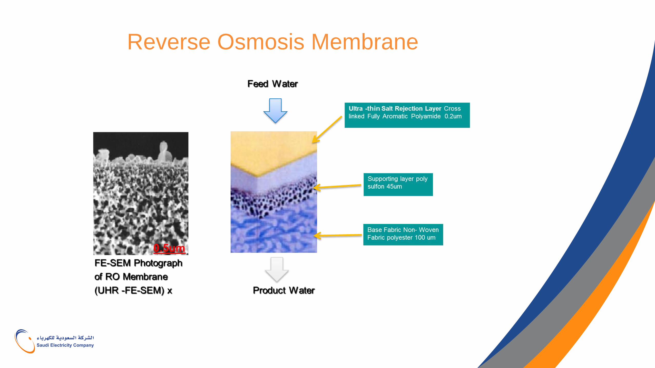
Reverse Osmosis Membrane
The RO Membrane
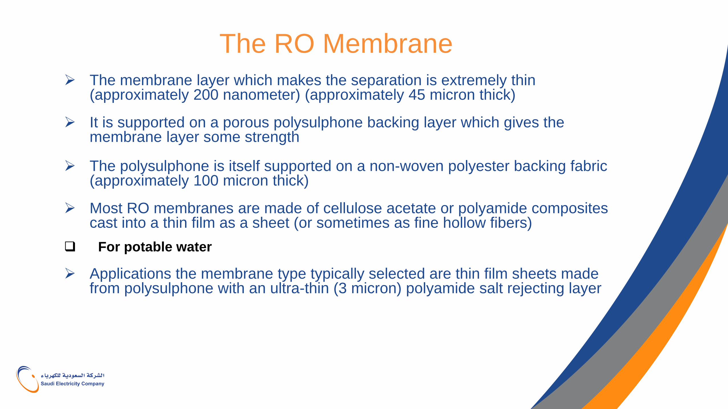
The membrane layer which makes the separation is extremely thin (approximately 200 nanometer) (approximately 45 micron thick)
It is supported on a porous polysulphone backing layer which gives the
membrane layer some strength The polysulphone is itself supported on a non-woven polyester backing fabric
(approximately 100 micron thick) Most RO membranes are made of cellulose acetate or polyamide composites
cast into a thin film as a sheet (or sometimes as fine hollow fibers) For potable water Applications the membrane type typically selected are thin film sheets made
from polysulphone with an ultra-thin (3 micron) polyamide salt rejecting layer
Anatomy of a spiral wound element
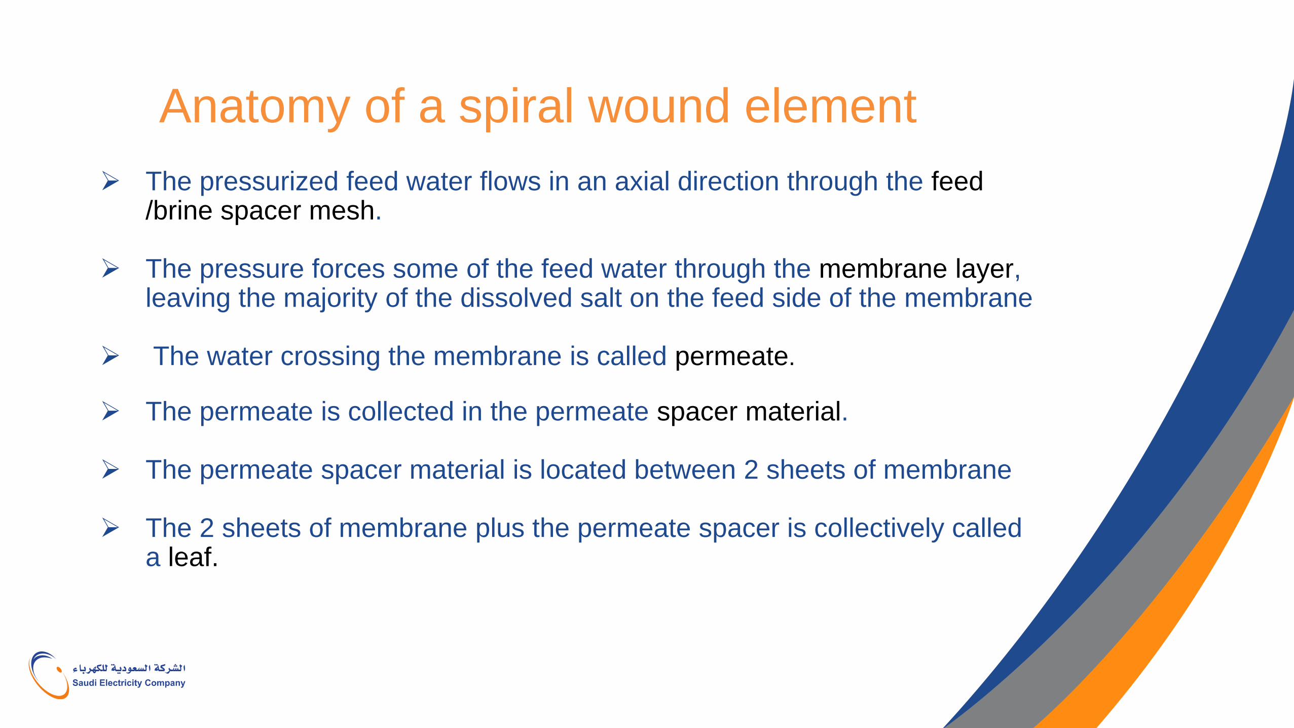
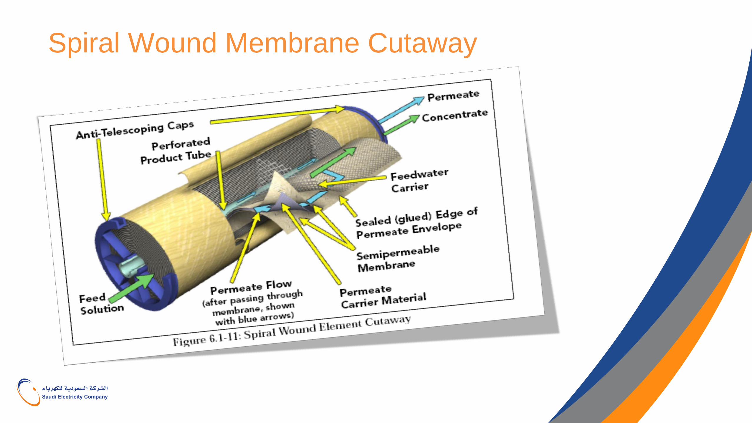
The pressurized feed water flows in an axial direction through the feed /brine spacer mesh.
The pressure forces some of the feed water through the membrane layer, leaving the majority of the dissolved salt on the feed side of the membrane
The water crossing the membrane is called permeate.
The permeate is collected in the permeate spacer material.
The permeate spacer material is located between 2 sheets of membrane
The 2 sheets of membrane plus the permeate spacer is collectively called a leaf.
Spiral Wound Membrane Cutaway
Principle of Reveres Osmosis
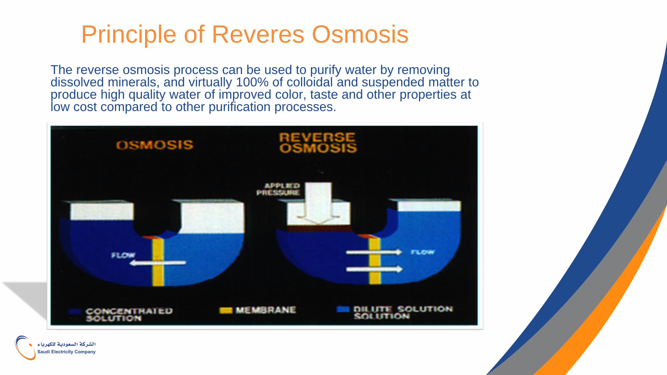
The reverse osmosis process can be used to purify water by removing dissolved minerals, and virtually 100% of colloidal and suspended matter to produce high quality water of improved color, taste and other properties at low cost compared to other purification processes.
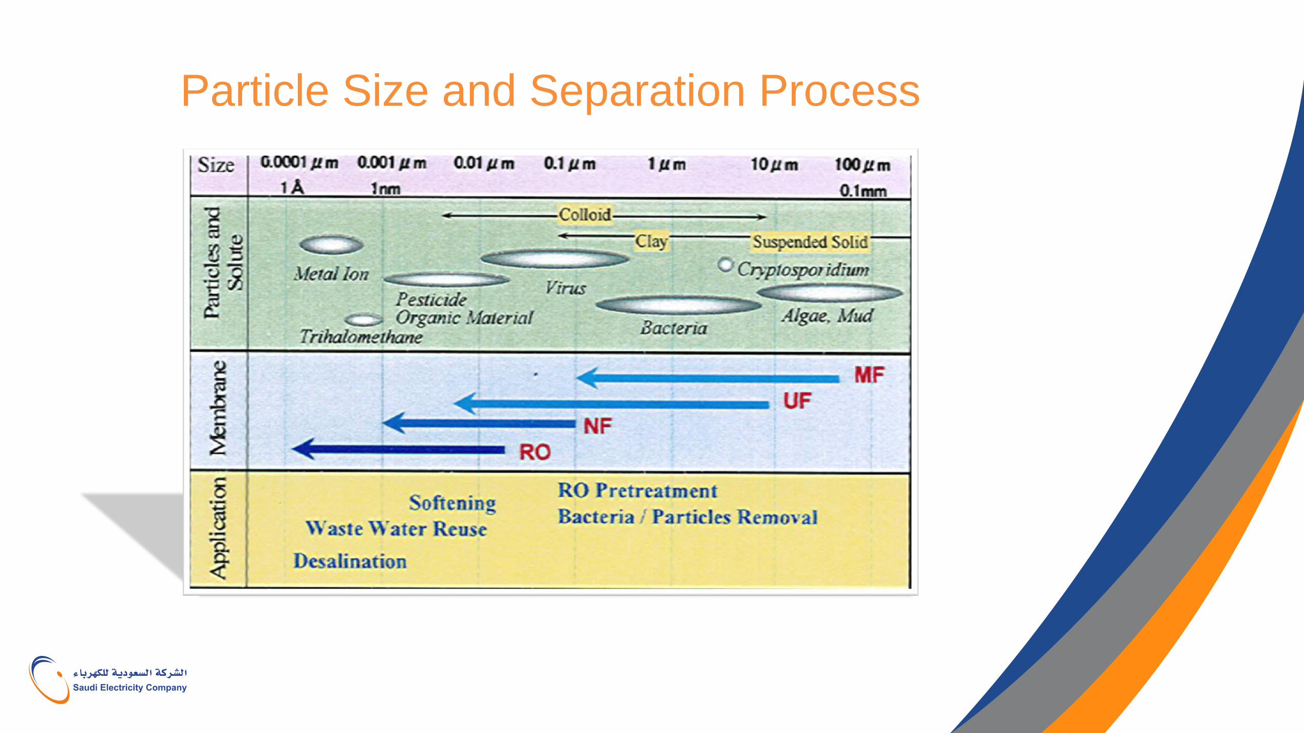
Particle Size and Separation Process
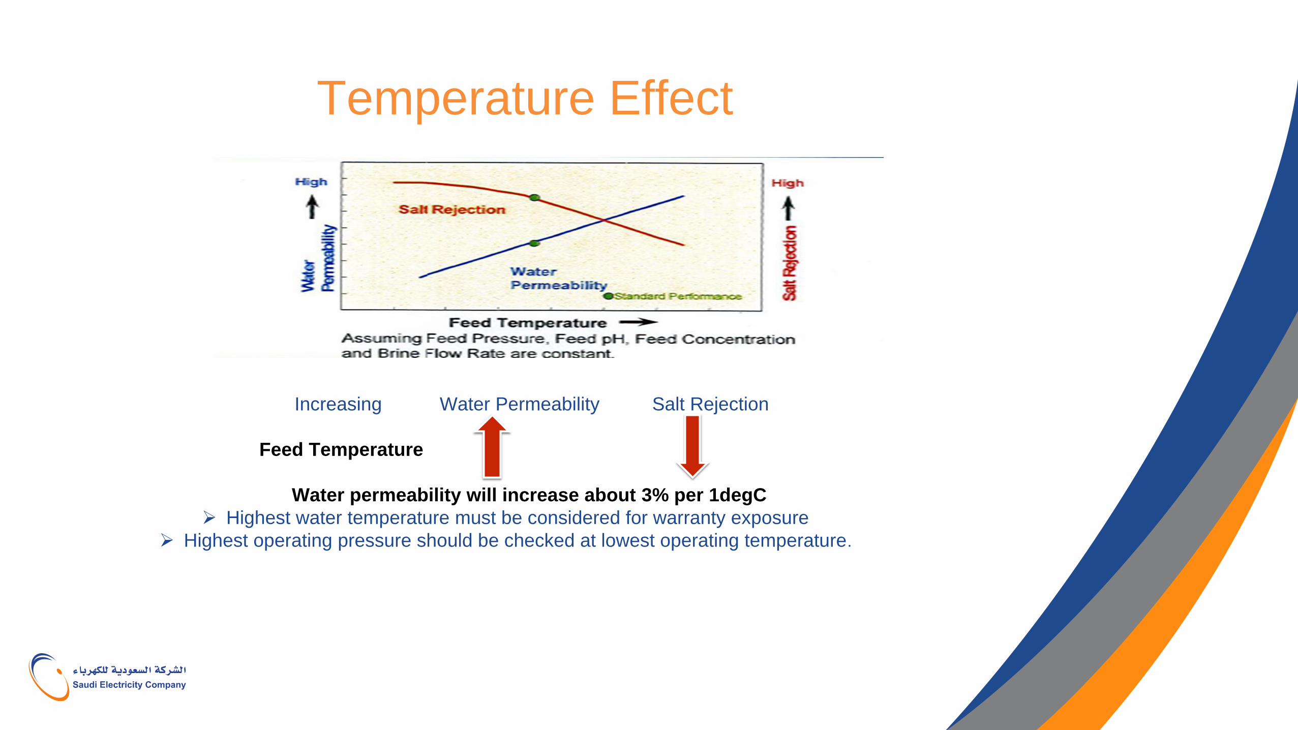
Temperature Effect
Increasing Water Permeability Salt Rejection
Feed Temperature
Water permeability will increase about 3% per 1degC
Highest water temperature must be considered for warranty exposure
Highest operating pressure should be checked at lowest operating temperature.
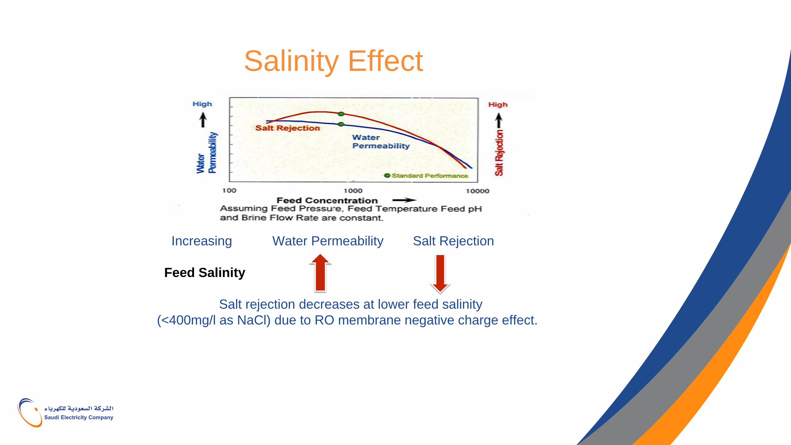
Salinity Effect
Increasing Water Permeability Salt Rejection
Feed Salinity
Salt rejection decreases at lower feed salinity
(<400mg/l as NaCl) due to RO membrane negative charge effect.
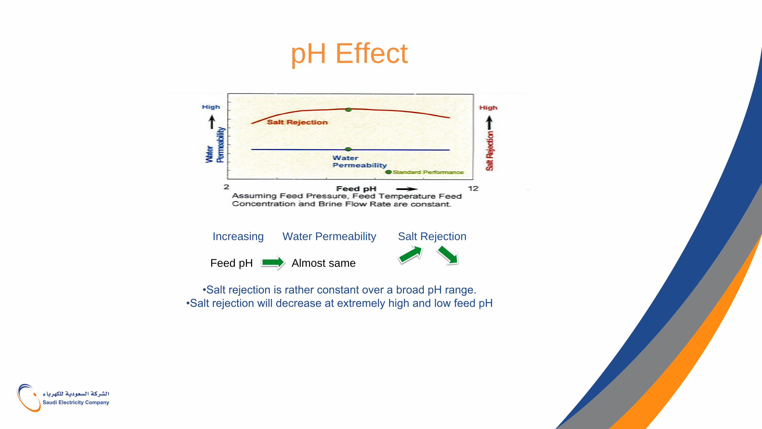
pH Effect
Increasing Water Permeability Salt Rejection
Feed pH Almost same
•Salt rejection is rather constant over a broad pH range.
•Salt rejection will decrease at extremely high and low feed pH
What is Boron
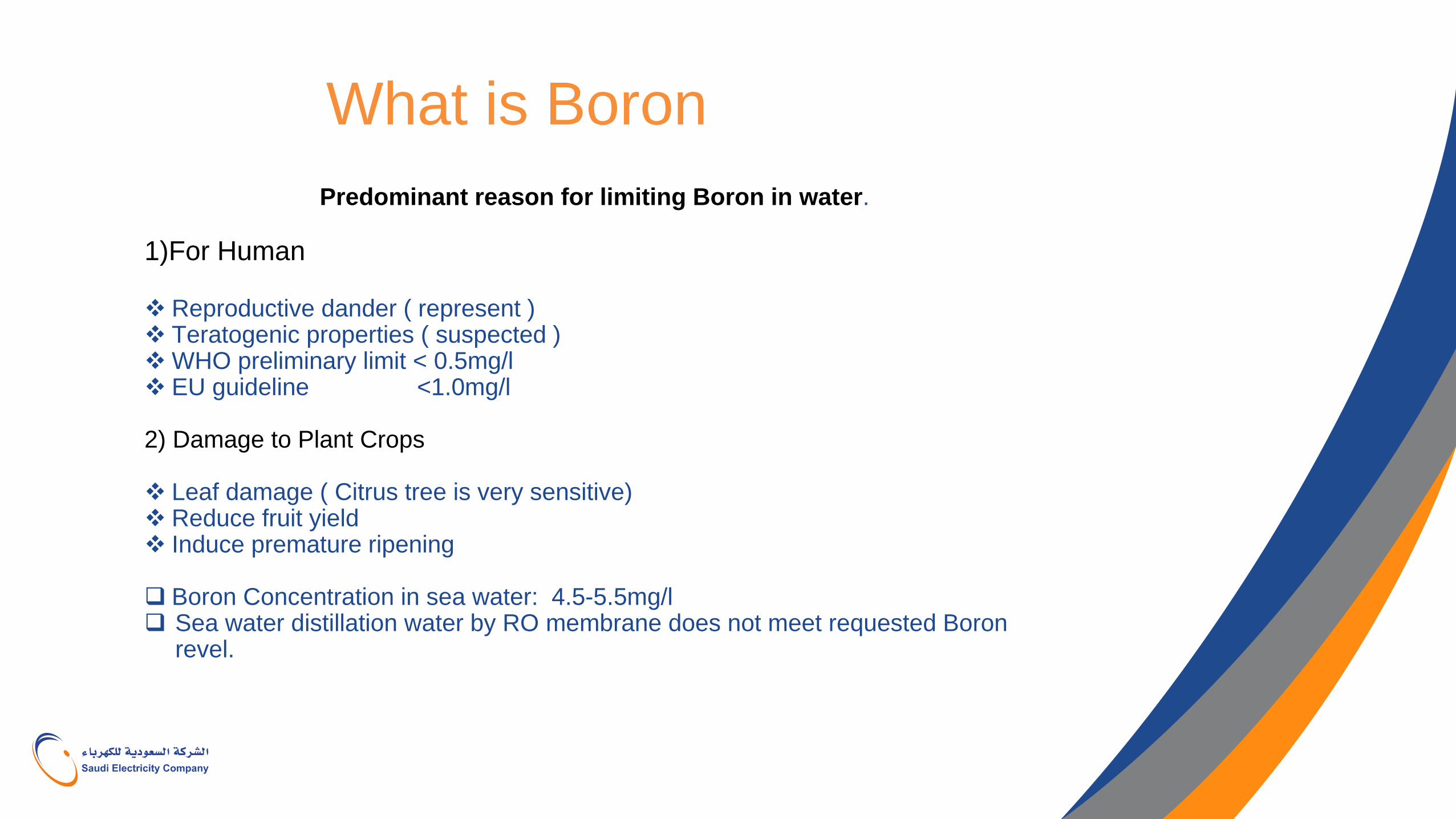
Predominant reason for limiting Boron in water.
1)For Human Reproductive dander ( represent ) Teratogenic properties ( suspected ) WHO preliminary limit < 0.5mg/l EU guideline <1.0mg/l
2) Damage to Plant Crops Leaf damage ( Citrus tree is very sensitive) Reduce fruit yield Induce premature ripening Boron Concentration in sea water: 4.5-5.5mg/l Sea water distillation water by RO membrane does not meet requested Boron
revel.
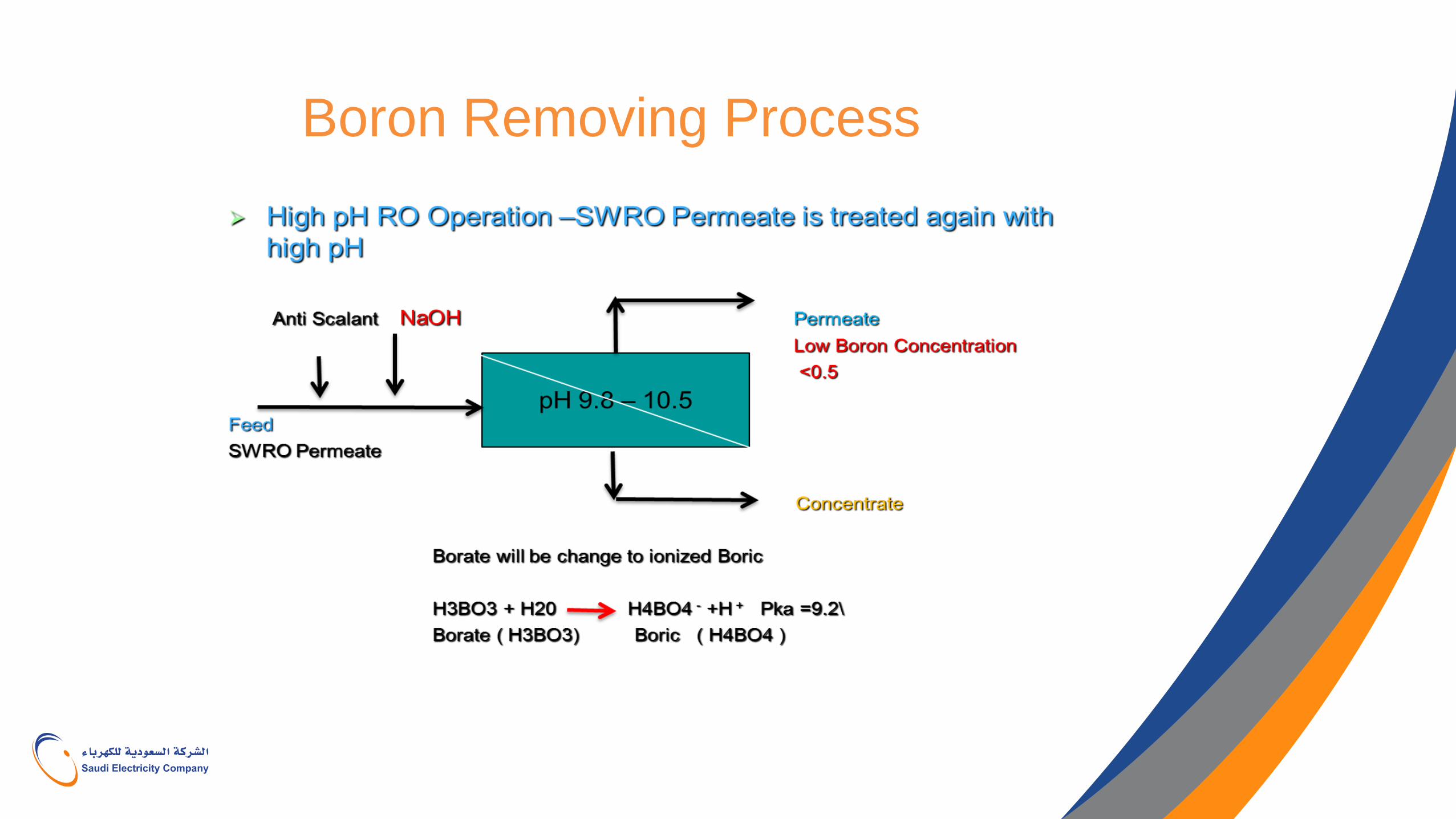
Boron Removing Process
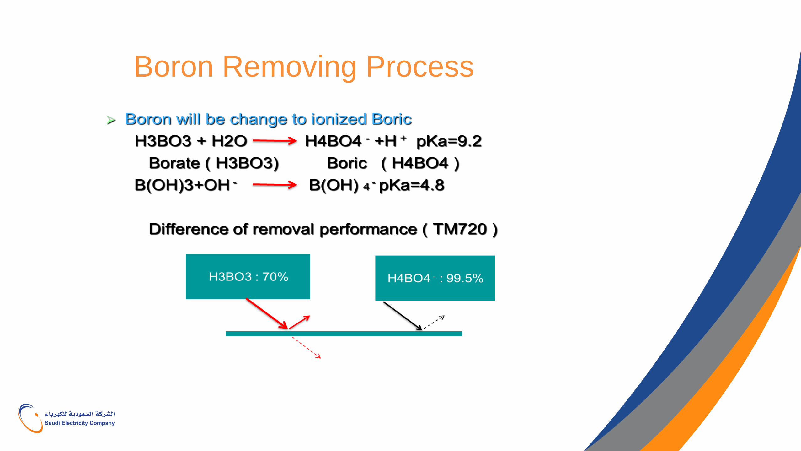
Boron Removing Process
Common Causes of RO System Problem
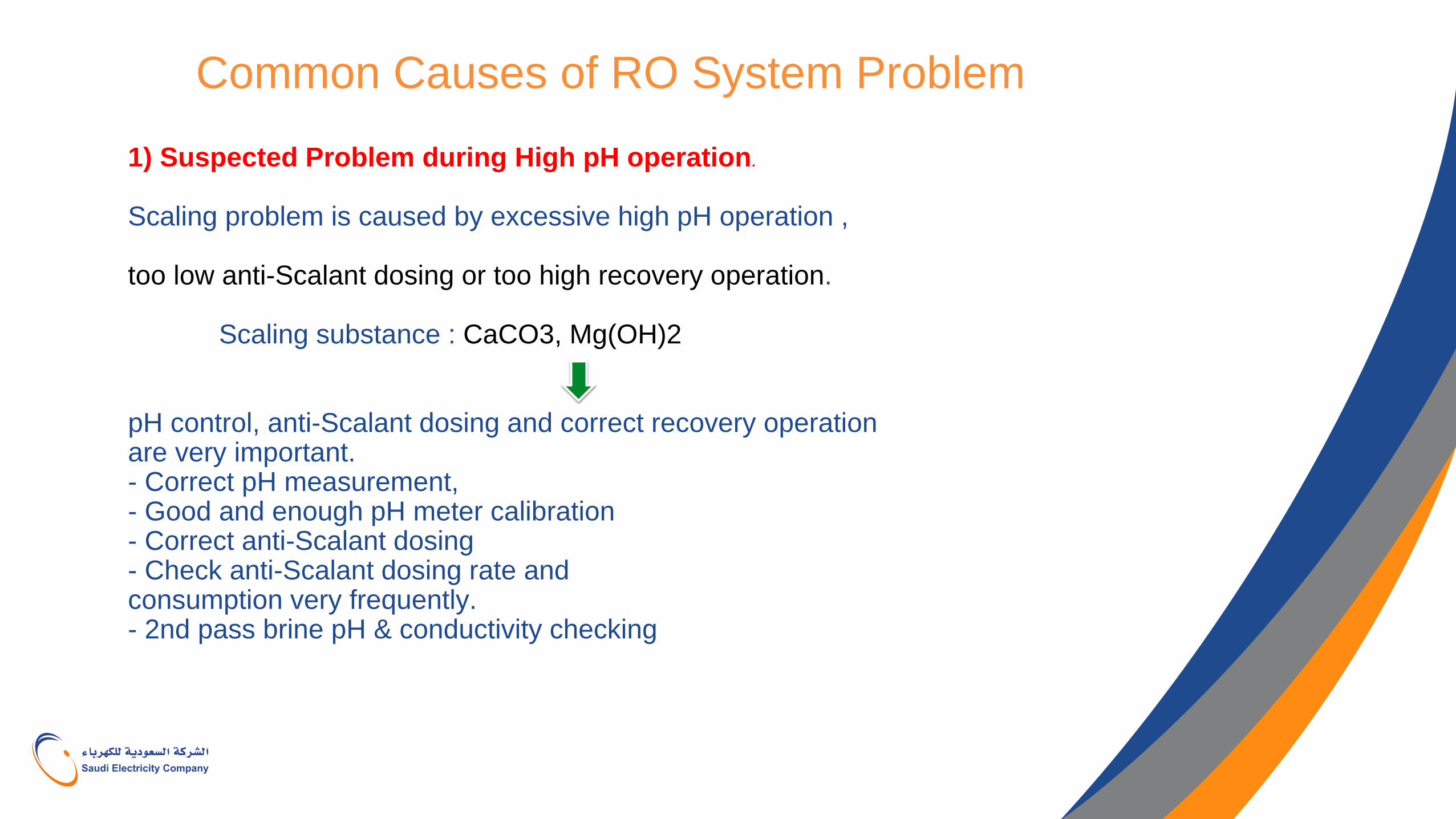
1) Suspected Problem during High pH operation.
Scaling problem is caused by excessive high pH operation , too low anti-Scalant dosing or too high recovery operation. Scaling substance : CaCO3, Mg(OH)2 pH control, anti-Scalant dosing and correct recovery operation are very important. - Correct pH measurement, - Good and enough pH meter calibration - Correct anti-Scalant dosing - Check anti-Scalant dosing rate and consumption very frequently. - 2nd pass brine pH & conductivity checking
Common Causes of RO System Problem
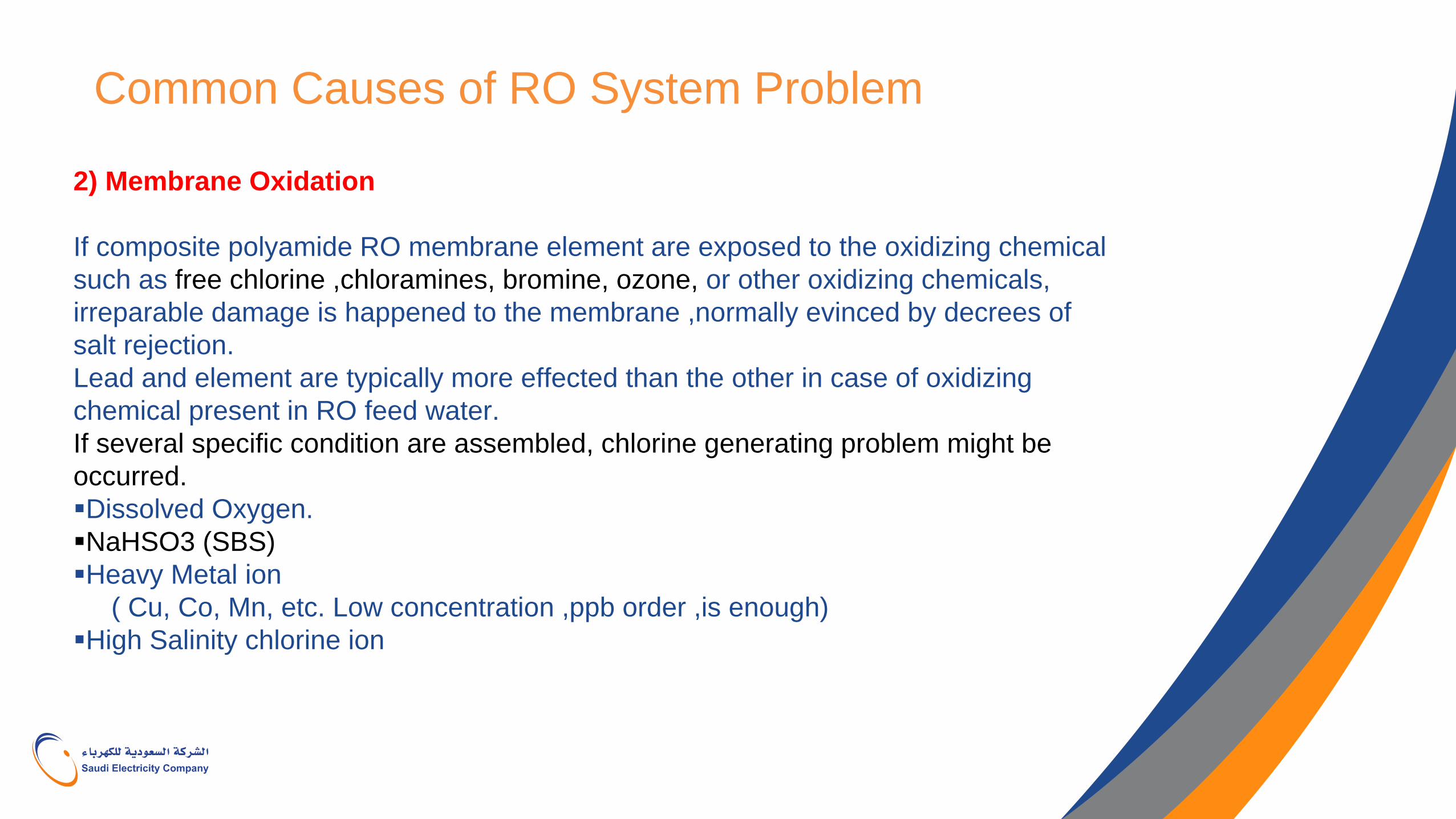
2) Membrane Oxidation
If composite polyamide RO membrane element are exposed to the oxidizing chemical
such as free chlorine ,chloramines, bromine, ozone, or other oxidizing chemicals,
irreparable damage is happened to the membrane ,normally evinced by decrees of
salt rejection.
Lead and element are typically more effected than the other in case of oxidizing
chemical present in RO feed water.
If several specific condition are assembled, chlorine generating problem might be
occurred.
Dissolved Oxygen.
NaHSO3 (SBS)
Heavy Metal ion
( Cu, Co, Mn, etc. Low concentration ,ppb order ,is enough)
High Salinity chlorine ion
Common Causes of RO System Problem
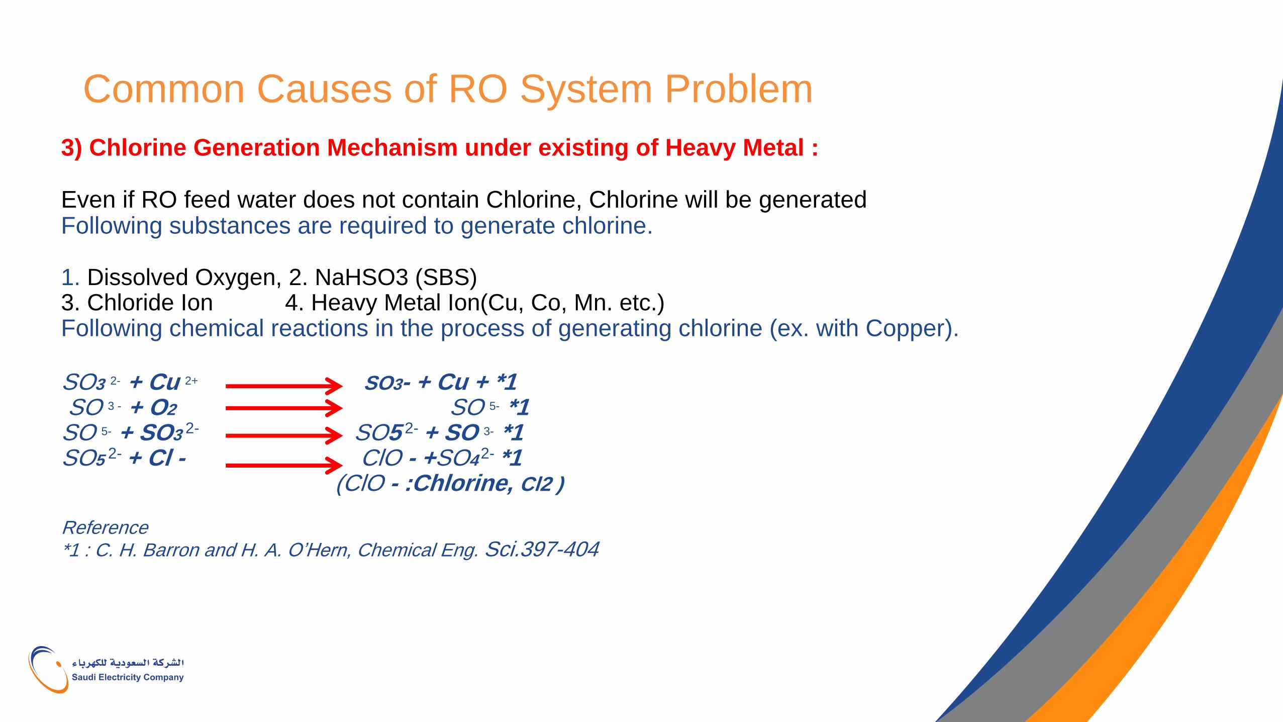
3) Chlorine Generation Mechanism under existing of Heavy Metal : Even if RO feed water does not contain Chlorine, Chlorine will be generated Following substances are required to generate chlorine. 1. Dissolved Oxygen, 2. NaHSO3 (SBS) 3. Chloride Ion 4. Heavy Metal Ion(Cu, Co, Mn. etc.) Following chemical reactions in the process of generating chlorine (ex. with Copper). SO3 2- + Cu 2+ SO3- + Cu + *1 SO 3 - + O2 SO 5- *1 SO 5- + SO3 2- SO5 2- + SO 3- *1 SO5 2- + Cl - ClO - +SO4 2- *1 (ClO - :Chlorine, Cl2 ) Reference *1 : C. H. Barron and H. A. O’Hern, Chemical Eng. Sci.397-404
Common Causes of RO System Problem
4) High Permeate TDS Poor permeate quality can be caused by the following: Changes in operating conditions Damage to membrane (oxidants, hydrolysis, etc..) Fouling Mechanical Leakage
5) Causes of Mechanical Leakage O-ring leak Interconnector or Permeate Tube crack Glue Line failure Membrane de lamination Membrane fracture Membrane mechanical abrasion Membrane degradation through chemical exposure
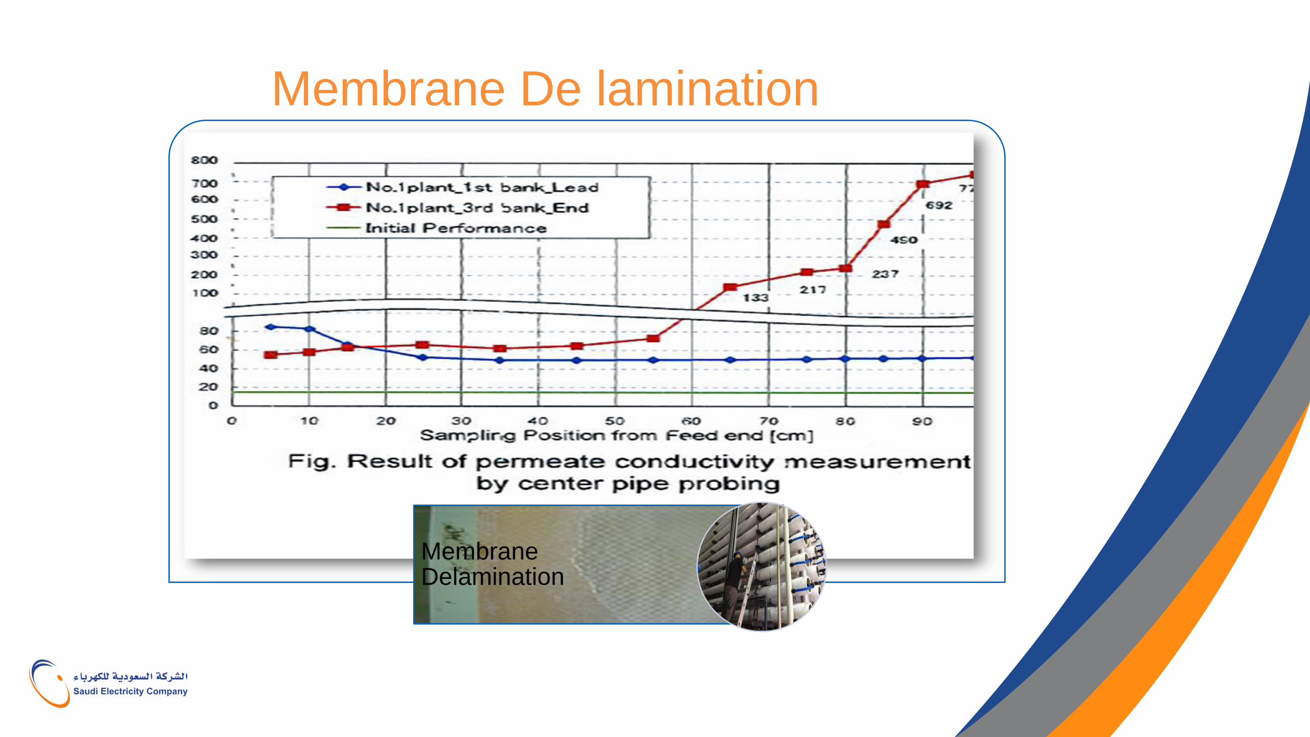
Membrane De lamination
Membrane Delamination
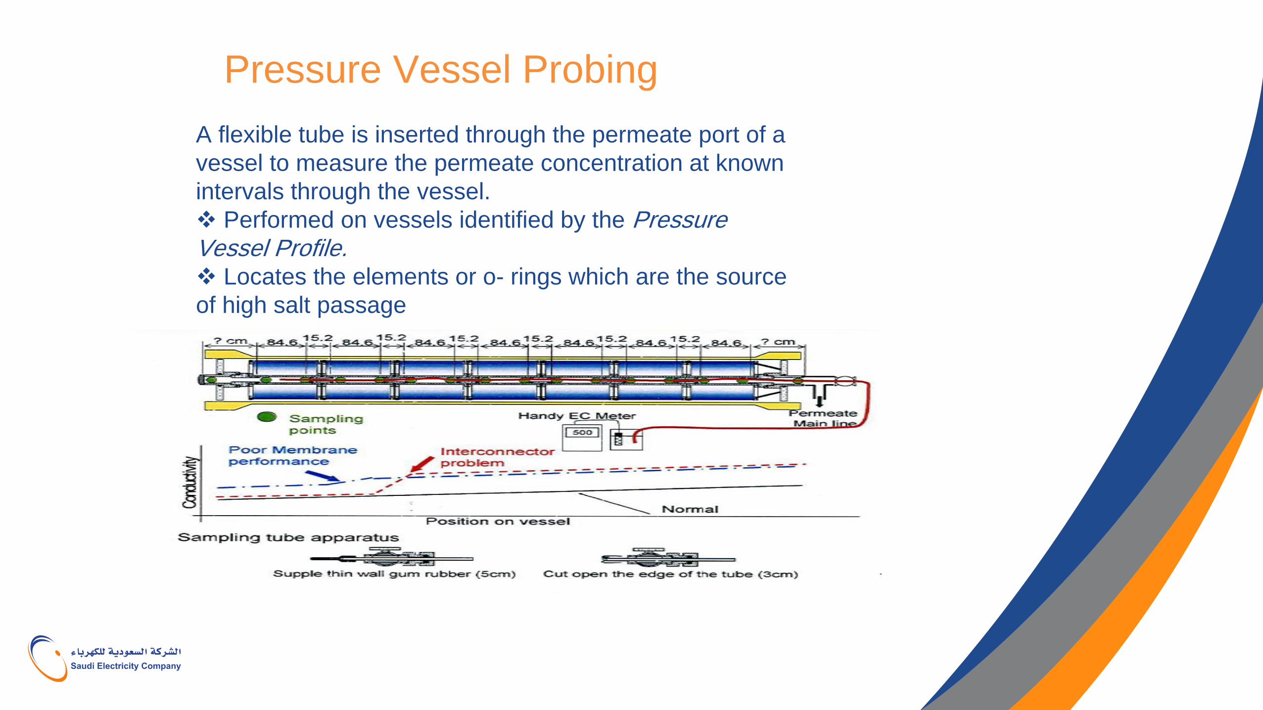
Pressure Vessel Probing
A flexible tube is inserted through the permeate port of a
vessel to measure the permeate concentration at known
intervals through the vessel.
Performed on vessels identified by the Pressure Vessel Profile. Locates the elements or o- rings which are the source
of high salt passage
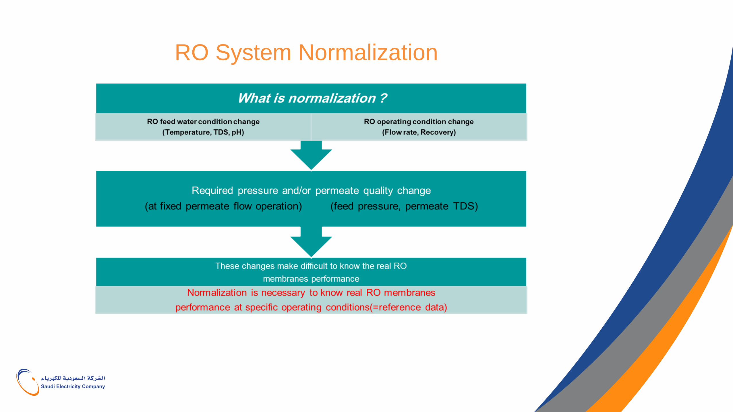
RO System Normalization
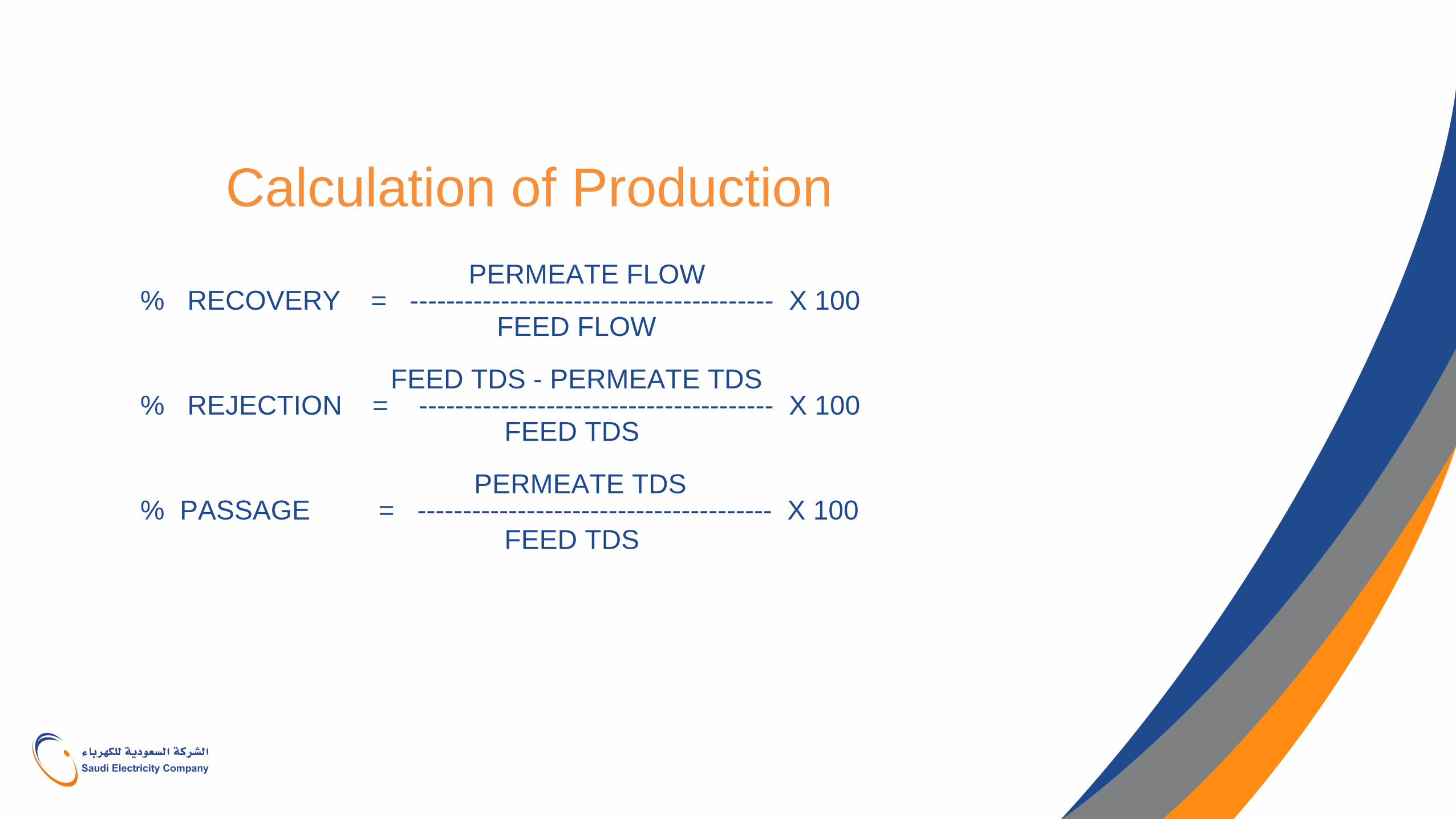
Calculation of Production
PERMEATE FLOW % RECOVERY = ---------------------------------------- X 100 FEED FLOW FEED TDS - PERMEATE TDS % REJECTION = --------------------------------------- X 100 FEED TDS PERMEATE TDS % PASSAGE = --------------------------------------- X 100 FEED TDS
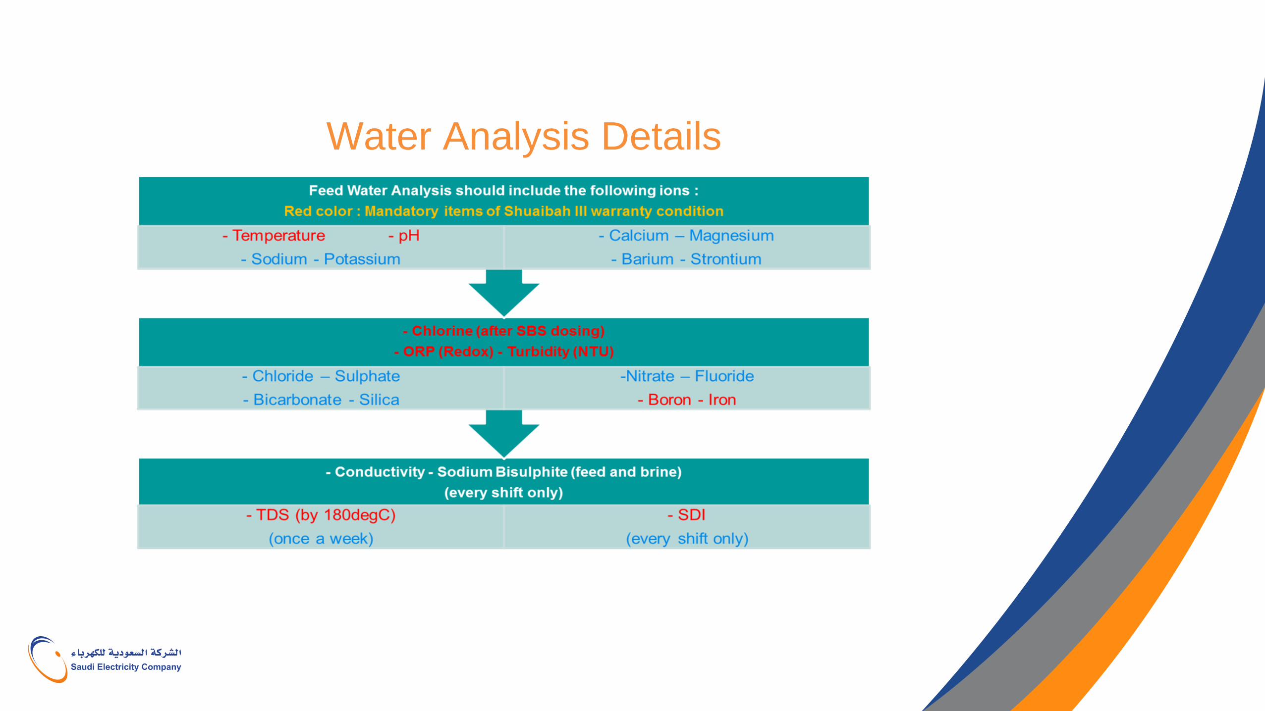
Water Analysis Details
Fouling The deposition of suspended particles on the membrane
surface. oFoul ant on the membrane surface increases the resistance to the flow of water through the membrane.
oFouling causes lower productivity at constant net pressure or
higher net pressure at constant productivity.
oSometimes higher salt passage will be caused by fouling.
Membrane fouling is caused by.
Improper pretreatment system
pretreatment condition upset
Chemical dosing system upset
Improper material selection (piping, valve, pump, etc.)
Improper flushing after shutdown
Scaling by excess recovery ratio
Biological contamination in feed water
Feed water chemistry change
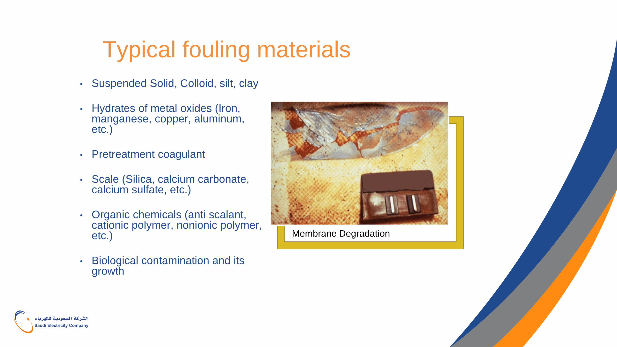
Typical fouling materials
• Suspended Solid, Colloid, silt, clay
• Hydrates of metal oxides (Iron, manganese, copper, aluminum, etc.)
• Pretreatment coagulant
• Scale (Silica, calcium carbonate, calcium sulfate, etc.)
• Organic chemicals (anti scalant, cationic polymer, nonionic polymer, etc.)
• Biological contamination and its growth
Membrane Degradation
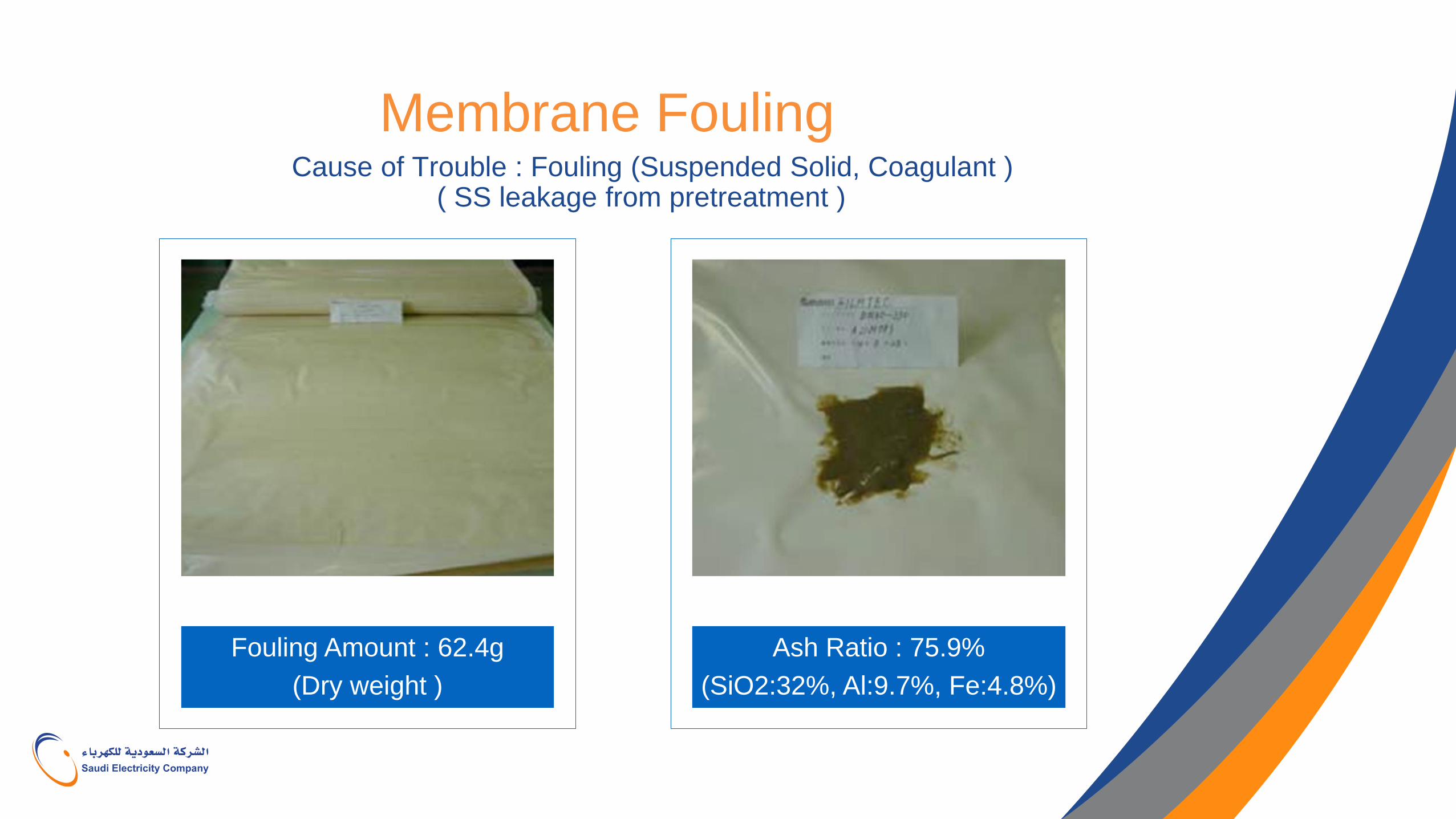
Membrane Fouling Cause of Trouble : Fouling (Suspended Solid, Coagulant )
( SS leakage from pretreatment )
Fouling Amount : 62.4g
(Dry weight )
Ash Ratio : 75.9%
(SiO2:32%, Al:9.7%, Fe:4.8%)
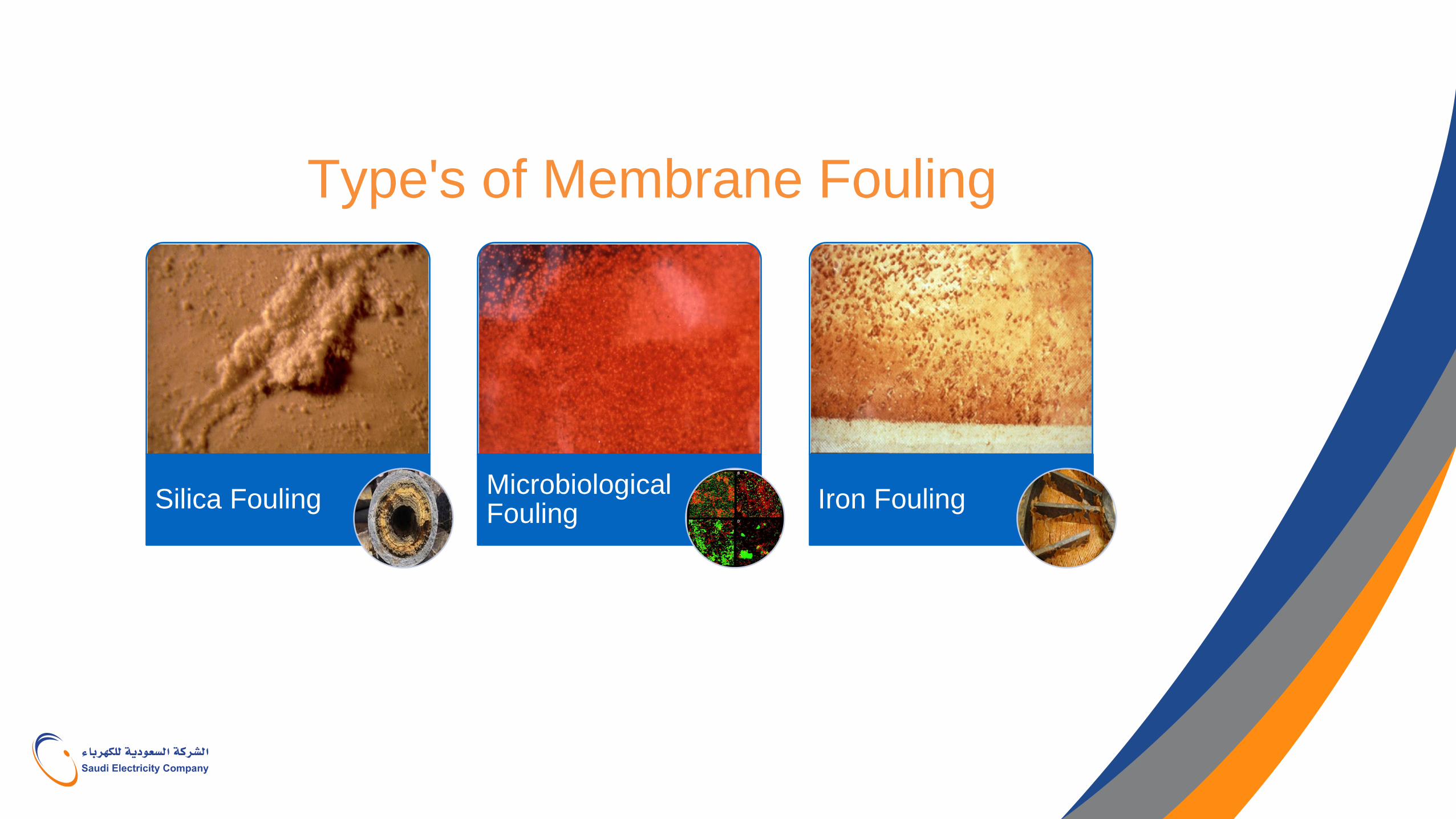
Type's of Membrane Fouling
Silica Fouling Microbiological Fouling
Iron Fouling
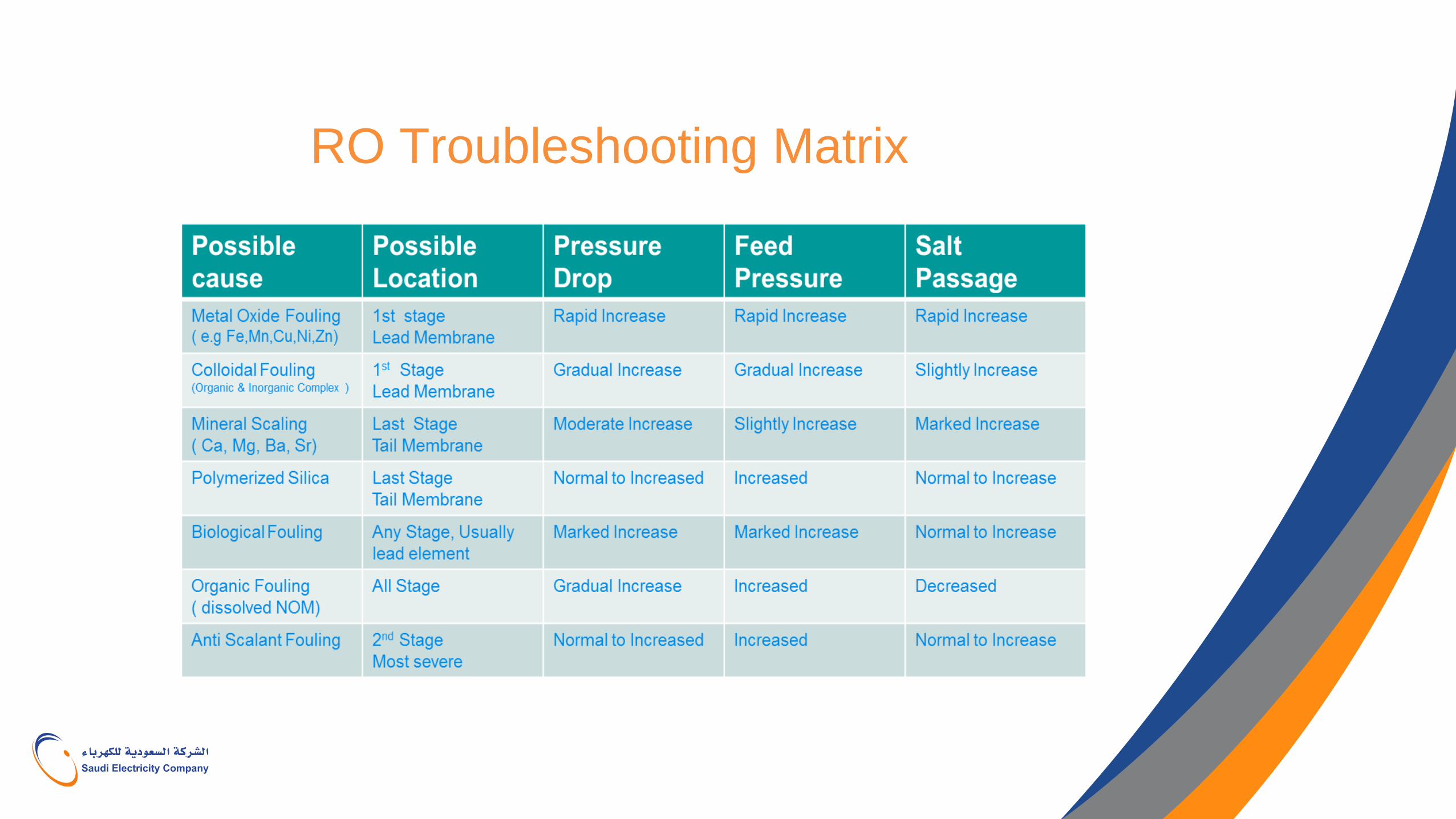
RO Troubleshooting Matrix
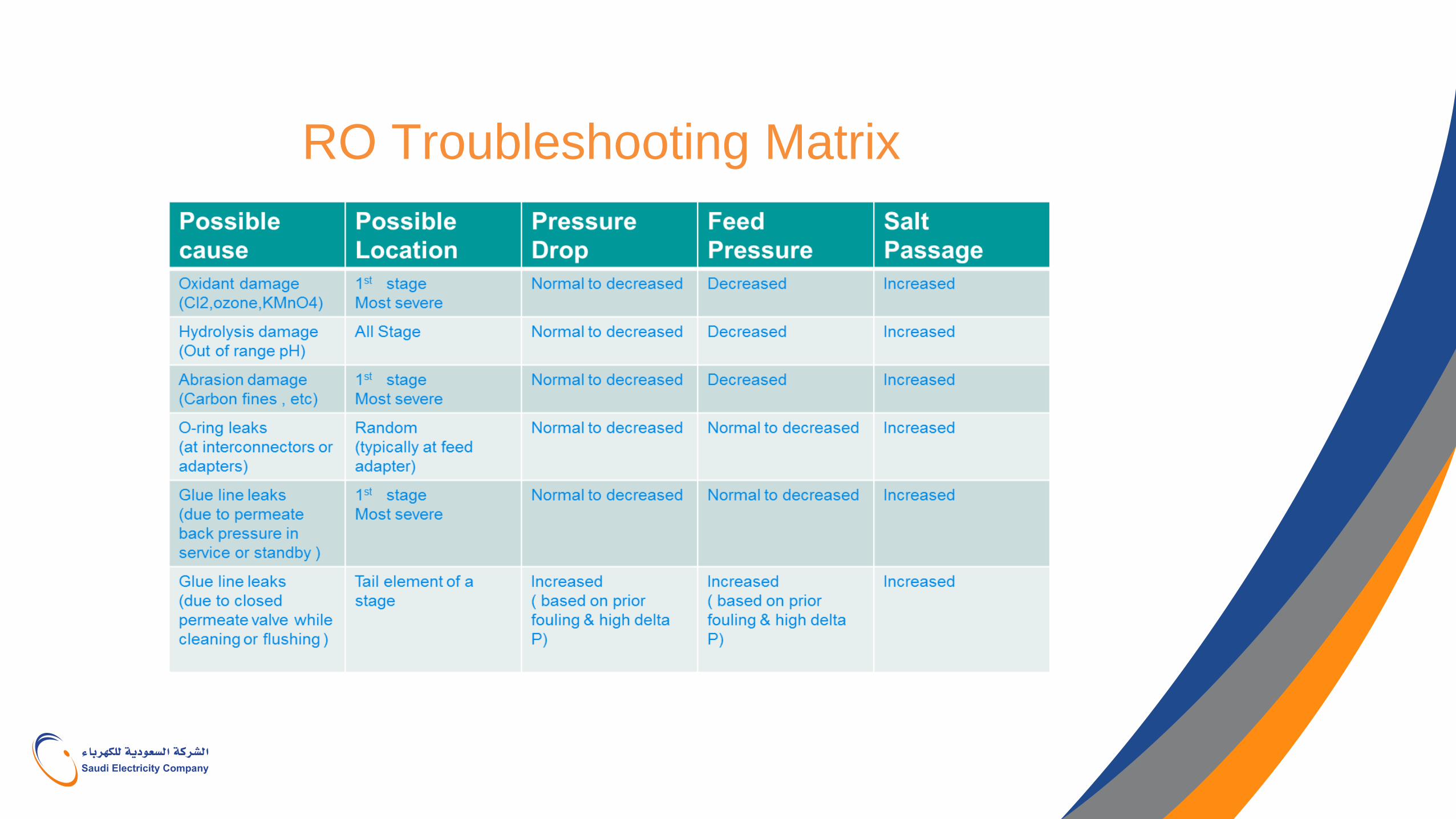
RO Troubleshooting Matrix
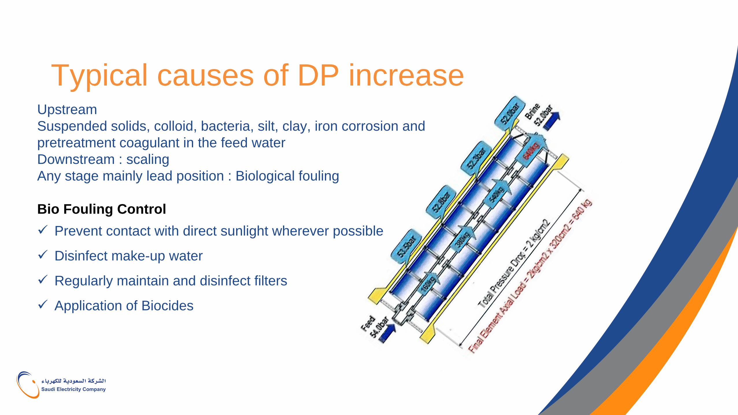
Typical causes of DP increase Upstream
Suspended solids, colloid, bacteria, silt, clay, iron corrosion and
pretreatment coagulant in the feed water
Downstream : scaling
Any stage mainly lead position : Biological fouling
Bio Fouling Control
Prevent contact with direct sunlight wherever possible
Disinfect make-up water
Regularly maintain and disinfect filters
Application of Biocides
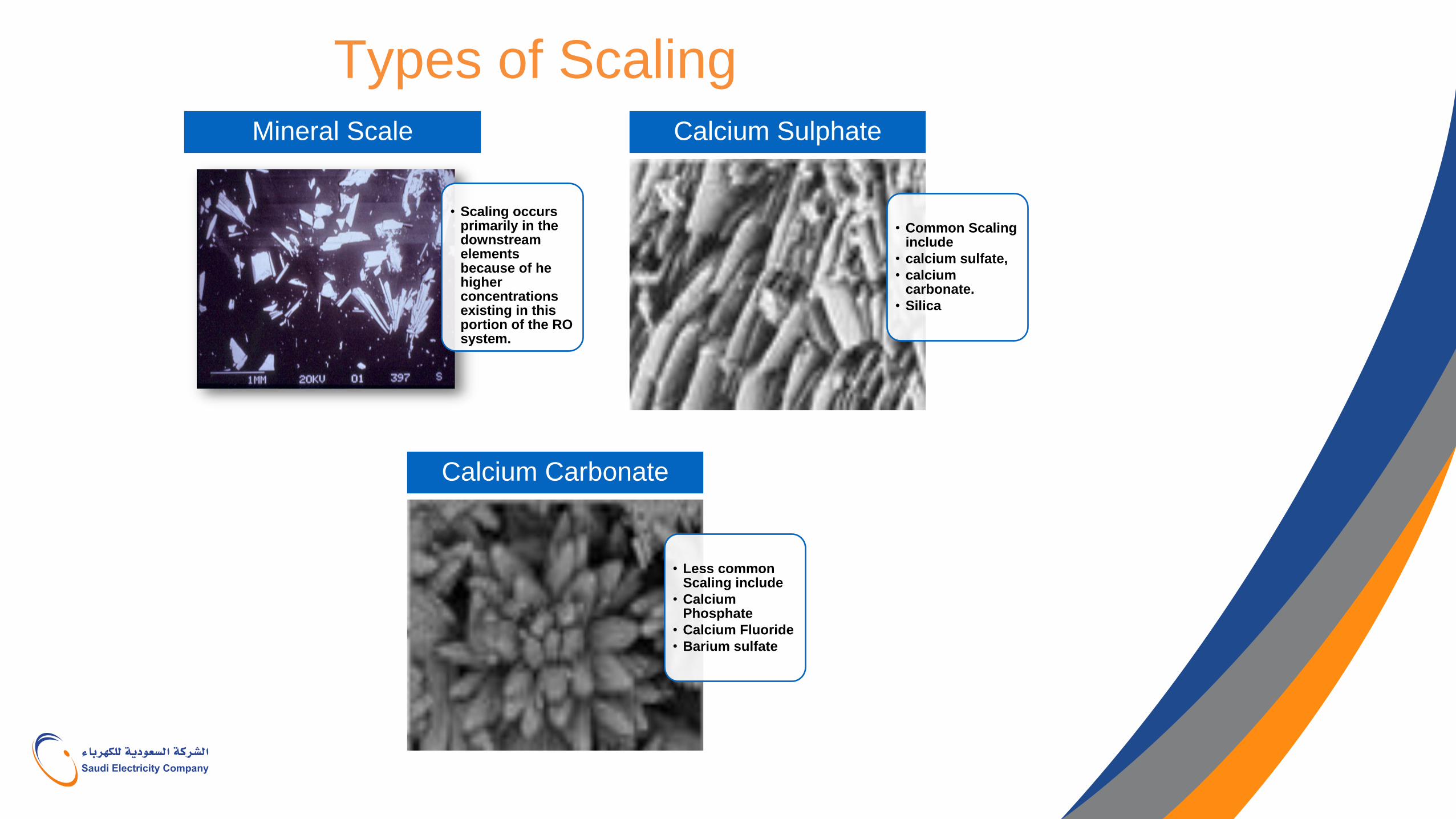
Types of Scaling
• Scaling occurs primarily in the downstream elements because of he higher concentrations existing in this portion of the RO system.
Mineral Scale
• Common Scaling include
• calcium sulfate,
• calcium carbonate.
• Silica
Calcium Sulphate
• Less common Scaling include
• Calcium Phosphate
• Calcium Fluoride
• Barium sulfate
Calcium Carbonate
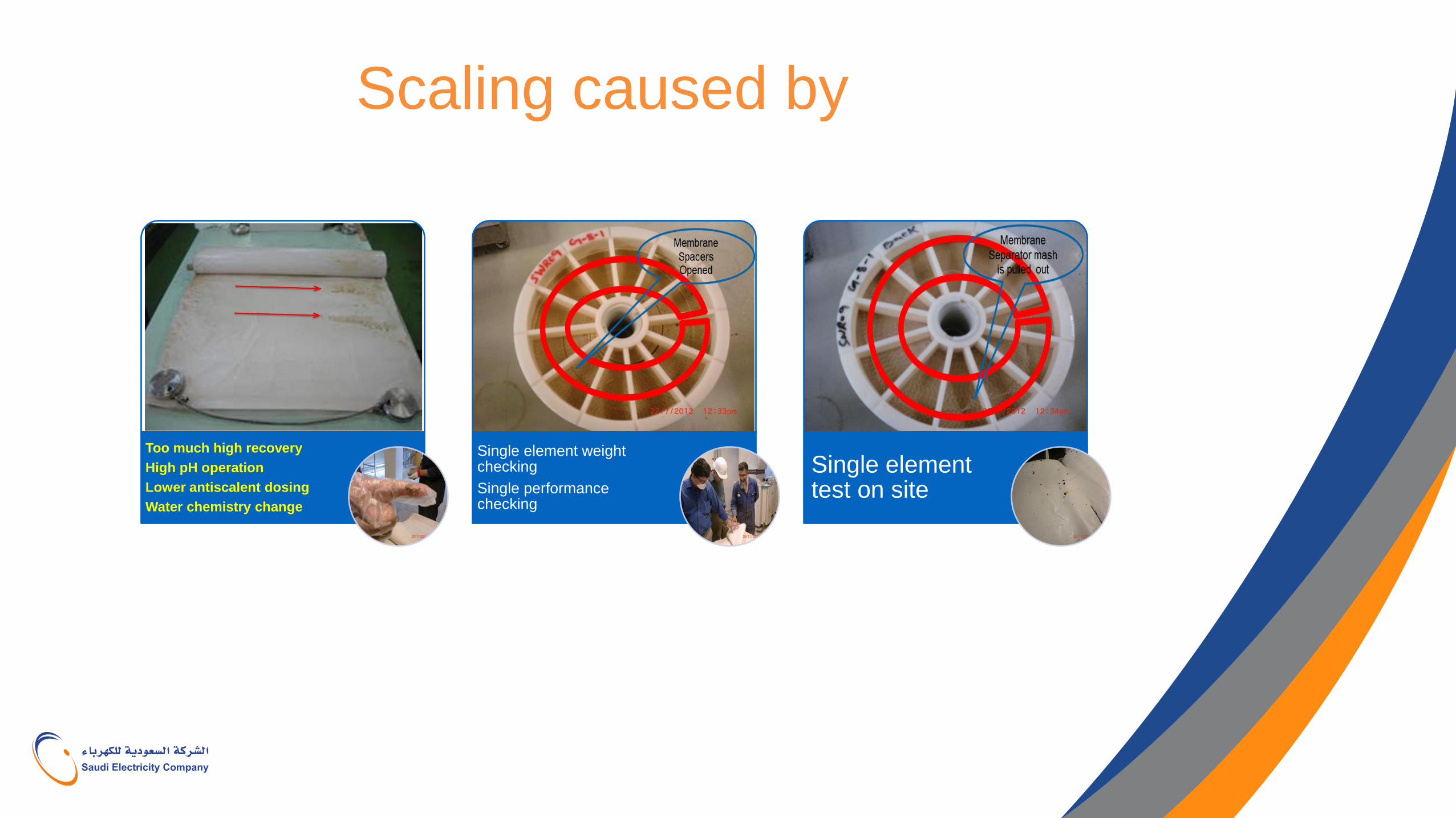
Scaling caused by
Too much high recovery
High pH operation
Lower antiscalent dosing
Water chemistry change
Single element weight checking
Single performance checking
Single element test on site
Single Element Performance Test on site
RO element outside visual checking
Single element weight checking
Single element performance checking
Measuring RO element weight after 30 min vertical standing
water drain.
New element weight : around 15 -16kg
(depend on water drain condition)
Weight checking will help to know fouling tendency in the pressure vessel.
RO element outside visual checking Single RO element performance measuring equipment on site is very helpful
To check RO membrane performance more reliably.
To check RO membrane performance before / after cleaning.
To carry out pre-cleaning test (if single element cleaning test is available)


