15-019 www.powercommander.com 2014 Harley Davidson Touring PCV - 1
PARTS LIST
1 PowerCommander1 USBCable1 InstallationGuide2 PowerCommanderDecals2 DynojetDecals2 Velcrostrips1 Alcoholswab1 FrontO2Optimizer1 RearO2Optimizer
THE LATEST POWER COMMANDERSOFTWARE AND MAP FILES CAN BE
DOWNLOADED FROM OUR WEB SITE AT:www.powercommander.com
2014 Harley Davidson Touring Model
I ns ta l l a t i on I ns t ruc t i ons
PLEASE READ ALL DIRECTIONS BEFORE STARTING INSTALLATION
THE IGNITION MUST BE TURNED OFF BEFORE INSTALLATION!
2191 Mendenhall Drive North Las Vegas, NV 89081 (800) 992-4993 www.powercommander.com

15-019 www.powercommander.com 2014 Harley Davidson Touring PCV - 2
EXPANSION PORTS 1 & 2
OptionalAccessoriessuchasPOD-300unitorAuto-tunekit.
POWER COMMANDER V INPUT ACCESSORY GUIDE
Map - (Input1or2)ThePCVhastheabilitytohold2differentbasemaps.YoucanswitchontheflybetweenthesetwobasemapswhenyouhookupaswitchtotheMAPinputs.Youcanuseanyopen/closetypeswitch.Thepolarityofthewiresisnotimportant.WhenusingtheAutotunekitonepositionwillholdabasemapandtheotherpositionwillletyouactivatethelearningmode.Whentheswitchis“CLOSED”Autotunewillbeactivated.(SettoSwitchInput#1bydefault.)
Shifter- (Input1or2)Usedforclutch-lessfullthrottleupshifts.InsertthewiresfromtheDynojetquickshifterintoeitherINPUT1orINPUT2.Thepolarityofthewiresisnotimportant.(SettoSwitchInput#2bydefault.)
Speed- NotneededonHarleyapplicationsasthespeedsignalwireisbuiltintothemainwiringharnessofthePCV.
Analog- Thisinputisfora0-5vsignalsuchasenginetemp,boost,etc.Oncethisinputisestablishedyoucanalteryourfuelcurvebasedonthisinputinthecontrolcentersoftware.
Launch- Youcanconnectawiretoeitherinput1or2andthentheotherendtoaswitch.Thisswitchwhenengaged(continuity)willonlyallowtheRPMtoberaisedtoacertainlimit(Setinthesoftware).WhenreleasedyouwillhavefullRPM.
ACCESSORY INPUTS
Wire connections:
ToinputwiresintothePCVfirstremovetherubberplugonthebacksideoftheunitandloosenthescrewforthecorrespondinginput.Usinga22-24gaugewirestripabout10mmfromitsend.PushthewireintotheholeofthePCVuntilisstopsandthentightenthescrew.Makesuretoreinstalltherubberplug.
NOTE:Ifyoutinthewireswithsolderitwillmakeinsertingthemeasier.
N/A
ANALOG
SPEED
INPUT 1 (Grnd)
INPUT 1
INPUT 2 (Grnd)
INPUT 2
USB CONNECTION
15-019 www.powercommander.com 2014 Harley Davidson Touring PCV - 3
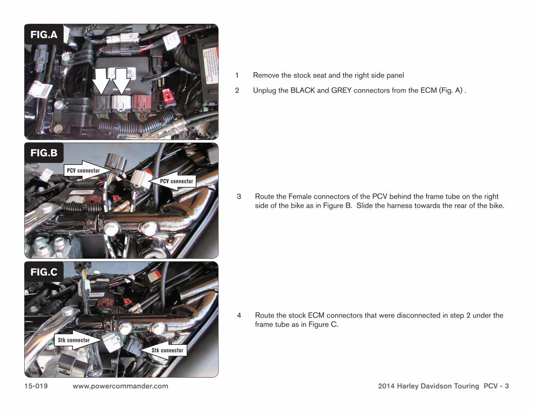
1 Removethestockseatandtherightsidepanel
2 UnplugtheBLACKandGREYconnectorsfromtheECM(Fig.A).
3 RoutetheFemaleconnectorsofthePCVbehindtheframetubeontherightsideofthebikeasinFigureB.Slidetheharnesstowardstherearofthebike.
4 RoutethestockECMconnectorsthatweredisconnectedinstep2undertheframetubeasinFigureC.
FIG.A
FIG.C
Remove
Ground wire
FIG.B
PCV connector
PCV connector
Stk connector
Stk connector
15-019 www.powercommander.com 2014 Harley Davidson Touring PCV - 4
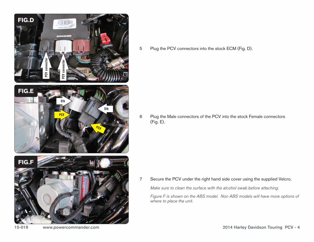
5 PlugthePCVconnectorsintothestockECM(Fig.D).
FIG.D
6 PlugtheMaleconnectorsofthePCVintothestockFemaleconnectors(Fig.E).
FIG.E
7 SecurethePCVundertherighthandsidecoverusingthesuppliedVelcro.
Make sure to clean the surface with the alcohol swab before attaching.
Figure F is shown on the ABS model. Non ABS models will have more options of where to place the unit.
FIG.F
PCV
conn
ecto
r
PCV
conn
ecto
r
PCV
PCV
Stk
Stk

15-019 www.powercommander.com 2014 Harley Davidson Touring PCV - 5
FIG.G
9 PlugtheDynojetO2Optimizersintothestockwiringharness(Fig.H).
The stock O2 sensors will NOT be connected to anything at this time. The sensors can be removed from the exhaust if you have a way to plug the hole.
FIG.H
FIG.I
8 LocatethestockO2sensorconnectionsandunplugbothconnectors(Fig.G).
There is a GREY 4 pin and a BLACK 4 pin connector under the right hand side cover.
Follow these instructions when using the Auto tune kit - (PN: AT-101B).
Refer to the Autotune install guide for the correct O2 sensor placement.
1 Removethelefthandsidecover.
2 PlacetheAutotunemodulenexttothePCVasshowninFigureI.
15-019 www.powercommander.com 2014 Harley Davidson Touring PCV - 6
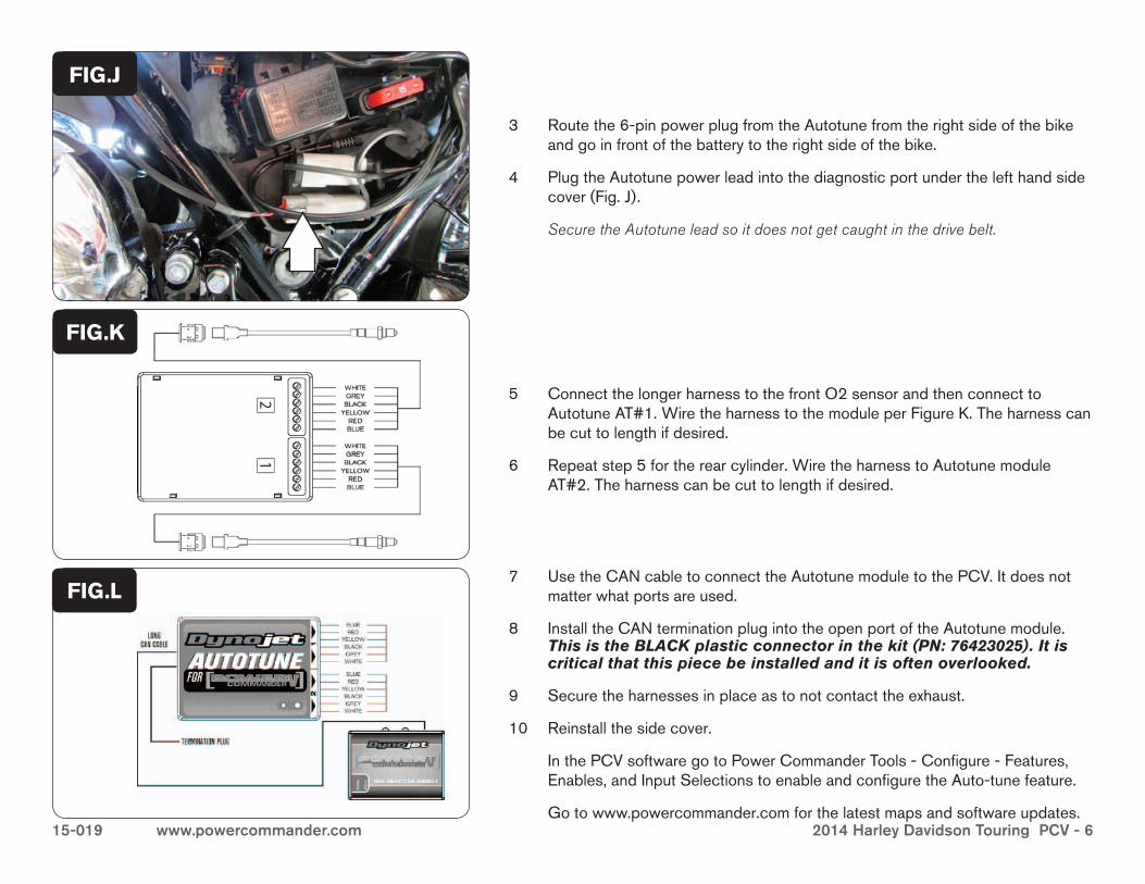
5 ConnectthelongerharnesstothefrontO2sensorandthenconnecttoAutotuneAT#1.WiretheharnesstothemoduleperFigureK.Theharnesscanbecuttolengthifdesired.
6 Repeatstep5fortherearcylinder.WiretheharnesstoAutotunemoduleAT#2.Theharnesscanbecuttolengthifdesired.
7 UsetheCANcabletoconnecttheAutotunemoduletothePCV.Itdoesnotmatterwhatportsareused.
8 InstalltheCANterminationplugintotheopenportoftheAutotunemodule.This is the BLACK plastic connector in the kit (PN: 76423025). It is critical that this piece be installed and it is often overlooked.
9 Securetheharnessesinplaceastonotcontacttheexhaust.
10 Reinstallthesidecover.
InthePCVsoftwaregotoPowerCommanderTools-Configure-Features,Enables,andInputSelectionstoenableandconfiguretheAuto-tunefeature.
Gotowww.powercommander.comforthelatestmapsandsoftwareupdates.
FIG.L
FIG.K
FIG.J
3 Routethe6-pinpowerplugfromtheAutotunefromtherightsideofthebikeandgoinfrontofthebatterytotherightsideofthebike.
4 PlugtheAutotunepowerleadintothediagnosticportunderthelefthandsidecover(Fig.J).
Secure the Autotune lead so it does not get caught in the drive belt.


