
I15-011 www.powercommander.com 2008-2013 Harley Davidson Touring PCV - 1
PARTS LIST
1 PowerCommander1 USBCable1 InstallationGuide2 PowerCommanderDecals2 DynojetDecals2 Velcrostrips1 Alcoholswab2 O2Optimizers
THE LATEST POWER COMMANDERSOFTWARE AND MAP FILES CAN BE
DOWNLOADED FROM OUR WEB SITE AT:www.powercommander.com
2008-2013 Harley Davidson Touring Model
I ns ta l l a t i on I ns t ruc t i ons
PLEASE READ ALL DIRECTIONS BEFORE STARTING INSTALLATION
THE IGNITION MUST BE TURNED OFF BEFORE INSTALLATION!
2191 Mendenhall Drive North Las Vegas, NV 89081 (800) 992-4993 www.powercommander.com

I15-011 www.powercommander.com 2008-2013 Harley Davidson Touring PCV - 2
EXPANSION PORTS 1 & 2
OptionalAccessoriessuchasPOD-300unitorAutotunekit.
POWER COMMANDER V INPUT ACCESSORY GUIDE
Map - (Input1or2)ThePCVhastheabilitytohold2differentbasemaps.YoucanswitchontheflybetweenthesetwobasemapswhenyouhookupaswitchtotheMAPinputs.Youcanuseanyopen/closetypeswitch.Thepolarityofthewiresisnotimportant.WhenusingtheAutotunekitonepositionwillholdabasemapandtheotherpositionwillletyouactivatethelearningmode.Whentheswitchis“CLOSED”Autotunewillbeactivated.(SettoSwitchInput#1bydefault.)
Shifter- (Input1or2)Usedforclutch-lessfullthrottleupshifts.InsertthewiresfromtheDynojetquickshifterintoeitherINPUT1orINPUT2.Thepolarityofthewiresisnotimportant.(SettoSwitchInput#2bydefault.)
Speed- NotneededonHarleyapplicationsasthespeedsignalwireisbuiltintothemainwiringharnessofthePCV.
Analog- Thisinputisfora0-5vsignalsuchasenginetemp,boost,etc.Oncethisinputisestablishedyoucanalteryourfuelcurvebasedonthisinputinthecontrolcentersoftware.
Launch- Youcanconnectawiretoeitherinput1or2andthentheotherendtoaswitch.Thisswitchwhenengaged(continuity)willonlyallowtheRPMtoberaisedtoacertainlimit(Setinthesoftware).WhenreleasedyouwillhavefullRPM.
ACCESSORY INPUTS
Wire connections:
ToinputwiresintothePCVfirstremovetherubberplugonthebacksideoftheunitandloosenthescrewforthecorrespondinginput.Usinga22-24gaugewirestripabout10mmfromitsend.PushthewireintotheholeofthePCVuntilisstopsandthentightenthescrew.Makesuretoreinstalltherubberplug.
NOTE:Ifyoutinthewireswithsolderitwillmakeinsertingthemeasier.
N/A
ANALOG
SPEED
INPUT 1 (Grnd)
INPUT 1
INPUT 2 (Grnd)
INPUT 2
USB CONNECTION

I15-011 www.powercommander.com 2008-2013 Harley Davidson Touring PCV - 3
1 Removethestockseat.
2 UnplugthestockwiringharnessfromtheECM(Fig.A).
3 PlugthePCVconnectorsin-lineofthestockECMandwiringharness(Fig.B).
4 TuckthePCVtowiringharnessconnectionintotheopeninginfrontofthebatterybox(Fig.C).
5 UsingthesuppliedVelcro,attachthePCVtothetopoftheECM(Fig.C).
Clean both surfaces with the supplied alcohol swab prior to applying the Velcro adhesive.
FIG.A
Remove
Ground wire
FIG.B
PCV connector
PCV connector
Stk connector
Connection
FIG.C

I15-011 www.powercommander.com 2008-2013 Harley Davidson Touring PCV - 4
Note: Figure D along with Steps 6 & 7 only apply to 2010-2013 models. If installing to a 2008-2009 model, proceed to Figures E-F and Steps 8-11.
6 Removetherighthandsaddlebagandsidecover.
7 LocatethestockO2sensorconnectionsandunplugbothconnectors(Fig.D)
The stock O2 sensors will NOT be connected to anything at this time. The sensors can be removed from the exhaust if you have a way to plug the hole.
Unplugging the sensors does NOT cause an engine light but will cause a historic code in the ECM for non-active O2 sensor. This is not causing any issues with the running of the bike.
FIG.D
Note: Figure E-F along with steps 8-11 only apply to 2008-2009 models.
8 LocateandunplugthefrontstockO2sensorconnection(Fig.E).
This connector is located directly in front of the engine. You can trace the wires from the front O2 sensor to this connector.
9 PlugoneofthesuppliedO2OptimizersintothestockwiringharnessinplaceofthestockfrontO2sensor.
FIG.E
10 LocateandunplugthestockrearO2sensorconnection(Fig.F).
This connection is located near the right-hand side of the starter.
11 PlugoneofthesuppliedO2OptimizersintothestockwiringharnessinplaceofthestockrearO2sensor.
The stock O2 sensors will no longer be connected to anything. If using the Auto-tune (PN: AT-100) remove the stock O2 sensors from the exhaust, and install the Dynojet wideband O2 sensors in their place.
FIG.F
Unplug
Unplug

I15-011 www.powercommander.com 2008-2013 Harley Davidson Touring PCV - 5
Follow these instructions when using the Auto-tune kit - part #AT-100 or AT-100B.
1 Removethelefthandsidecover.
2 PlacetheAuto-tunemodulenexttothePCVasshowninFigureG.
FIG.G
3 Removetherubberplugforthediagnosticconnector.PlugtheleadfromtheAuto-tunekitintothestockdiagnosticconnector(Fig.H).ThisconnectionisundertheLHsidecover.DONOTconnecttotheaccessoryconnectioninfrontofthebattery.
4 Reinstallthesidecover.
FIG.H
5 ConnectthelongerharnesstothefrontO2sensor.RoutetheharnessalongthefrontdowntubeandalongthebackboneoftheframetoAuto-tunemoduleAT#1.WiretheharnesstothemoduleperFigureJ.Theharnesscanbecuttolengthifdesired.
6 Repeatstep4fortherearcylinder.WiretheharnesstoAuto-tuneModuleAT#2.Theharnesscanbecuttolengthifdesired.
If your exhaust does not accept the 18mm x 1.5 size O2 sensor you will need to install the supplied O2 bungs with the Auto-tune kit into your exhaust (AT-100B kit only). See Auto-tune instructions for more information.
FIG.J
I15-011 www.powercommander.com 2008-2013 Harley Davidson Touring PCV - 6
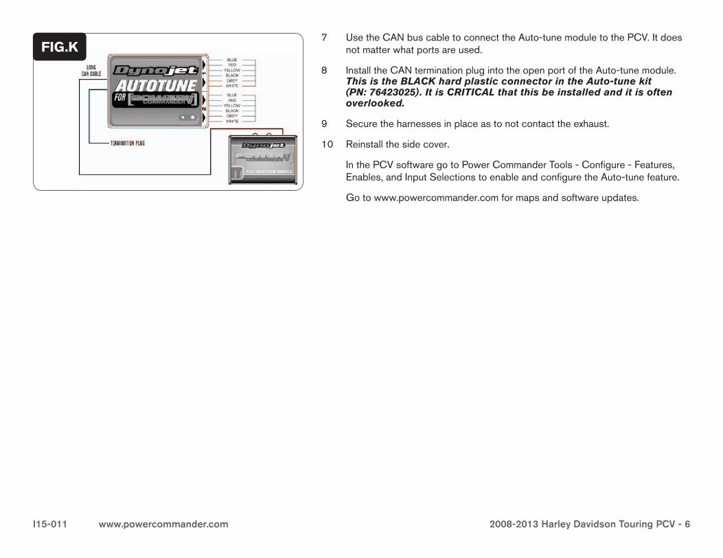
7 UsetheCANbuscabletoconnecttheAuto-tunemoduletothePCV.Itdoesnotmatterwhatportsareused.
8 InstalltheCANterminationplugintotheopenportoftheAuto-tunemodule.This is the BLACK hard plastic connector in the Auto-tune kit (PN: 76423025). It is CRITICAL that this be installed and it is often overlooked.
9 Securetheharnessesinplaceastonotcontacttheexhaust.
10 Reinstallthesidecover.
InthePCVsoftwaregotoPowerCommanderTools-Configure-Features,Enables,andInputSelectionstoenableandconfiguretheAuto-tunefeature.
Gotowww.powercommander.comformapsandsoftwareupdates.
FIG.K


